

Page 1
MX420 Navigation System
Installation & Service Manual
Page 2

MX420 Navigation System
Installation and Service Manual
Models Covered:
MX420/2
MX420/8
MX420/BR
MX420/BRIM
MX420/AIS BASIC (MKD)
MX420/AIS DGPS
Prepared by
MX Marine
A Division of NAVICO, Inc.
23868 Hawthorne Boulevard, Suite 201
Torrance, California 90505-5908
USA
Page 3

P/N 3508 102 70060
July, 2007
MX Marine
MX Marine reserves the right to make changes to its products and specifications without
notice.
Copyright July, 2007
Page 4

About This Manual
We at MX Marine have attempted to take care and develop manuals which provide in-depth
information. Obviously, we can’t anticipate every configuration in which you might install the
MX420, but we can help make your work more thorough and enjoyable.
This manual is organized by first describing the list of included items for the particular model
you purchased. The sections that follows detail the technical specifications of the MX420
navigation unit and the MX421 antenna unit. This is followed with the mechanical and electrical
wiring diagrams and installation notes to guide you in the installation of your MX420 system.
Should you require additional technical support, please first contact the dealer where you
purchased your MX420. Since your dealer sells and installs the MX420 and many other types
of equipment, they are often your best resource for technical questions. You can also contact
MX Marine for technical assistance:
International:
We hope you find the manual enjoyable and informative. As always, we welcome your
comments on improving our products or manuals. Thank you.
Product Information
The model and serial number of your instrument are given on the back of the unit. Please enter
the serial number in the space provided below. Always refer to this information when you
contact your dealer.
Model: MX420 Navigation System S/N ___________________
MX Marine (US)
A Division of NAVICO, Inc.
23868 Hawthorne Blvd., Suite 201
Torrance, California 90505
USA
+01-310-791-8213 Telephone (International)
+01-310-791-6108 Fax
info@mx-marine.com
www.mx-marine.com
Notes:
Page 5

Page 6

Table of Contents
SECTION 1 - LIST OF COMPONENTS ...................................................... 1
SECTION 2 - TECHNICAL SPECIFICATIONS ............................................ 9
SECTION 3 - MECHANICAL AND INSTALLATION DRAWINGS ............... 17
SECTION 4 - ELECTRICAL INSTALLATION DRAWINGS ........................ 25
Figure 4.1 MX420/2 Basic System Configuration ............................ 27
Figure 4.2 MX420/2 Basic Wiring Diagram ...................................... 28
Figure 4.3 MX420/8 System Configuration ...................................... 29
Figure 4.4 MX420/8 Wiring Diagram .............................................. 30
Figure 4.5 MX420/BR Dual Control System ..................................... 31
Figure 4.6 MX420/BR Dual Control Wiring Diagram ....................... 32
Figure 4.7 MX420/BRIM Dual Station Integrity Monitor System ..... 33
Figure 4.8 MX420/BRIM Dual Station Integrity Monitor Interface
Diagram ............................................................................................. 34
Figure 4.9 Cable (A) Wiring Configuration ...................................... 35
Figure 4.10 Cable (B) Wiring Configuration (Only on MX420/8) ... 36
Figure 4.11 Cable (C) Wiring Configuration (Only on MX420/8) .... 37
Figure 4.12 MX420/2 Rear Panel Connector .................................... 38
Figure 4.13 MX420/8 Rear Panel Connectors .................................. 38
Figure 4.14 MX421(8-Pin) GPS Antenna Wiring Diagram ............... 39
Figure 4.15 MX421-10 (10-Pin) GPS Only Antenna Wiring Diagram40
Figure 4.16 MX421B-10 (10-Pin) DGPS Antenna Wiring Diagram .. 41
Figure 4.17 MX420/AIS CDU & MX423 (SAAB) Transponder System
Block Diagram .................................................................................. 43
Figure 4.18 MX420/AIS CDU & MX423 (SAAB) Transponder System
Wiring Diagram ................................................................................ 44
Figure 4.19 MX420/AIS/MKD CDU & MX531 (ATLAS) Transponder
Block Diagram .................................................................................. 45
Figure 4.20 - MX420/AIS/MKD CDU & MX531 (ATLAS) Transponder
System Wiring Diagram ................................................................... 46
Figure 4.21 MX420/AIS/MKD CDU & MX535 (NAUTICAST) Tran-
sponder Block Diagram .................................................................... 47
Figure 4.22 - MX420/AIS/MKD CDU & MX535 (NAUTICAST) Tran-
sponder System Wiring Diagram ..................................................... 48
Figure 4.23 - MX420/AIS/MKD CDU & MX535 (NAUTICAST) Tran-
sponder System Wiring Diagram with JB-50 Junction Box ............ 49
SECTION 5 ............................................................................................... 50
INSTALLATION NOTES ..................................................................... 50
GENERAL.....................................................................................52
Electronic Connections .................................................................... 52
Page 7

External Power ........................................................................... 52
Navigator Grounding. ................................................................ 53
MX421 GPS ANTENNA INSTALLATION ........................................... 53
Antenna Location ....................................................................... 53
Antenna Options ........................................................................ 53
Antenna Connector .................................................................... 53
Antenna Cable Options .............................................................. 54
External Differential Connection ................................................ 54
MX420 NAVIGATOR INSTALLATION ................................................ 54
Gimbal Mounting ....................................................................... 55
Flush Mounting .......................................................................... 55
Flush Mount Frame .................................................................... 55
Turning Power On and Off ......................................................... 55
EQUIPMENT INTERFACING........................................................ 56
Introduction .......................................................................... 56
External Man Over Board & Event (MX420/8 Only) ............ 56
Speed Over Ground Pulse Output ....................................... 57
External Alarm Output ......................................................... 57
Port 2: RS- 422 / RS- 232 Serial Interface ............................ 58
MX420 PC Interface .............................................................. 59
NMEA Interface .................................................................... 59
NMEA Interface to other Equipment ................................... 60
MX420 NMEA 0183 Sentences ................................................... 61
Data Format .......................................................................... 61
NMEA Output Sentences ..................................................... 62
Input NMEA 0183 Sentences ............................................... 63
Viewing Input Data ............................................................... 64
Dual Control (Remote) Interface ................................................. 65
MX420 Dual Control with Integrity Monitor .............................. 67
Other MX420/AIS Interface .................................................. 68
MX420 AIS Basic configuration .......................................... 69
MX423 AIS Transponder Interface ....................................... 69
Troubleshooting Guide .............................................................. 69
Memory Backup Battery ............................................................ 71
Backup Battery Replacement ..................................................... 71
MX420 PC Interface .................................................................... 71
Software Download Procedure .................................................. 71
Memory Clear Procedure: .......................................................... 72
Page 8

List of Components
MX 420 Installation and Service Manual
SECTION 1
LIST OF COMPONENTS
1
Page 9

MX 420 Installation and Service Manual List of Components
2
Page 10
List of Components
Item
Component Qty. Part Number
MX421B-10 Smar t DGPS
1
Antenna
MX521 Smart DGPS
2
Antenna
MX521G Smart GPS
3
Antenna
MX525 Smart DGPS
4
Antenna
MX525G Smart GPS
5
Antenna
MX575 D/ GPS Satellite
6
Compass
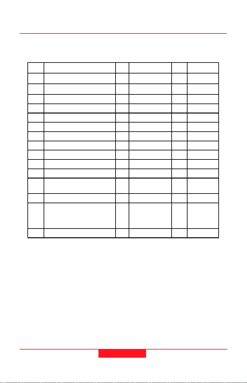
Table 1.1 Standard Parts for MX420/2 Model
MX 420 Installation and Service Manual
List of Components
Table 1.0 MX Marine Antenna Units
1
9525 200 80110
1
727010
1
727027
1
9525 200 80290
1
9525 200 80291
1
3508 102 70720
Remarks
Option
Option
Option
Option
Option
Option
Item Component Qty. Part Number
1.0 MX420/2 Control and Dis play
System Consisting of:
1.1 MX420, 2 Port Control and Display
Unit
1.2 Mounting Bracket 1 3508 101 38472
1.3 Mounting Kit 1 3508 102 03140
1.4 Power /NMEA Cable (Cable A) 1 3508 102 70010
1.5 MX420 Operator’s Manual 1 3508 102 70040
1.6 MX420 Operator’s Quick Guide 1 3508 102 70050
1.7 MX420 Installation/Service Manual 1 3508 102 70060
1.8 Tide Table Manual 1 3508 101 89490
2.0* MX421 Smart G PS antenna System*
Consisti ng of:
2.1 MX421-10 Smar t GPS Antenna* 1 9525 200 80100 1.1
2.2 Antenna Cable Options:
15 meters
20 meters
40 meters
90 meters
2.3 MX421 Installation Manual 1 723594
*GPS only model. For MX420/2B model substitute with MX421B-10 DGPS Antenna (see table below)
1 9525 200 78000
1 3508 102 70200 2.6
1 Not Included
725637
3508 102 70170
3508 102 70180
3508 102 70190
Wt
(lbs.)
Remarks
with Item 1.0
Option
Option
Option
Option
3
Page 11
MX 420 Installation and Service Manual List of Components
(
Table 1.2 Standard Parts for MX420/8 Model
Item Component Qty. Part Number Wt.
1.0 MX420/8 Control and Display
System Consisting of:
1.1 MX420, 8 Port Control and Display
Unit
1.2 Mounting Bracket 1 3508 101 38472
1.3 Mounting Kit 1 3508 102 03140
1.4 Power/NMEA Cable (Cable A) 1 3508 102 70010
1.5 Cable B NMEA Cable 1 3508 102 70020
1.6 Cable C NMEA Cable 1 3508 102 70030
1.7 MX420 Operator’s Manual 1 3508 102 70040
1.8 MX420 Operator’s Quick Guide 1 3508 102 70050
1.9 MX420 Installation/Service Manual 1 3508 102 70060
1.10 Tide Table Manual 1 3508 101 89490
2.0* MX421 Smart GPS antenna
System* Consisting of:
2.1 MX421-10 Smart GPS Antenna* 1 9525 200 80100 1.1
2.2 Antenna Cable Options:
15 meters
20 meters
40 meters
90 meters
2.3 MX421 Installation Manual 1 723594
1 9525 200 78010
1 3508 102 70210 2.6
1 Not Included
725637
3508 102 70170
3508 102 70180
3508 102 70190
(lbs.)
Remarks
with Item 1.0
Option
Option
Option
Option
GPS only antenna model. For MX420/8B model substitute with MX421B-10 DGPS antenna
See table below).
4
Page 12
List of Components
MX 420 Installation and Service Manual
Table 1.3 Standard Parts for MX420/BR Dual Control Display System
Component Qty. Wt.
1.0 MX420/8 Control and Display
System Consisting of:
1.1 MX420, 8 Port Control and Display
Unit
1.2 Mounting Bracket 2 3508 101 38472
1.3 Mounting Kit 2 3508 102 03140
1.4 Power/NMEA Cable (Cable A) 2 3508 102 70010
1.5 Cable B NMEA Cab le 1 3508 102 70020
1.6 Cable C NMEA Cable 1 3508 102 70030
1.7 MX420 Operator’s Manual 2 3508 102 70040
1.8 MX420 Operator’s Quick Guide 2 3508 102 70050
1.9 MX420 Installation/Service Manual 2 3508 102 70060
1.10 Tide Table Manual 2 3508 101 89490
2.0 MX420/2 Control and Display Unit 1 9525 200 78000
3.0* Smart GPS Antenna System
Consisting of :
MX421-10 Smart GPS Antenna
3.1*
Or,
MX421B-10 Smart DGPS Antenna11
3.2 Antenna Cable Options:
15 meters
20 meters
40 meters
90 meters
3.3 MX421 Installation Manual 1 723594
*GPS antenna for MX420/8 GPS only installation use P/N 9525 200 80100. For MX420/8B
DGPS installation use P/N 9525 200 80110.
1 9525 200 78010
1 3508 102 70210 2.6
1Not
9525 200 80100
9525 200 80110
1
725637
3508 102 70170
3508 102 70180
3508 102 70190
Remarks
(lbs.)
Included
with Item
1.0
1.1
1.9
Option
Option
Option
Option
5
Page 13
MX 420 Installation and Service Manual List of Components
Table 1.4 MX420/BRIM (Integrity Monitor) Model
Item Component Qty. Part Number Wt.
1.0 MX420/8 Control and Display
System consisting of:
1.1 MX420, 8 Port Control and Display
Unit
1.2 Mounting Bracket 2 3508 101 38472
1.3 Mounting Kit 2 3508 102 03140
1.4 Power/NMEA Cable (Cable A) 2 3508 102 70010
1.5 Cable B NMEA Cable 2 3508 102 70020
1.6 Cable C NMEA Cable 2 3508 102 70030
1.7 MX420 Operator’s Manual 2 3508 102 70040
1.8 MX420 Operator’s Quick Guide 2 3508 102 70050
1.9 MX420 Installation/Service Manual 2 3508 102 70060
Tide Table Manual 2 3508 101 89490
1.10
2.0 MX421 Smart DGPS Antenna
System
Consisting of:
2.1 MX421B Smart GPS Antenna 2 9525 200 80110 1.9
2.2 Antenna Cable Options:
15 meters
20 meters
40 meters
90 meters
2.3 MX421 Installation Manual 2 723594
2 9525 200 78010
2 3508 102 70210 2.6
2 Not Included
2
725637
3508 102 70170
3508 102 70180
3508 102 70190
(lbs.)
Remarks
with Item 1.0
Option
Option
Option
Option
6
Page 14

List of Components
MX 420 Installation and Service Manual
Table 1.5 MX420/AIS Model
Item # Description P/N Remarks
1.0
1.1
1.2 Mounting Bracket 3508 101 38472
1.3 Mounting Kit 3508 102 03140
1.4 Power/NMEA Cable (Cable A) 3508 102 70010
1.5 Cable B NMEA Cable 3508 102 70020
1.6 Cable C NMEA Cable 3508 102 70030
1.7 MX420 Operator’s Manual 3508 102 70410
1.8 MX420 Installation Manual 3508 102 70420
1.9 MX420 Quick Reference Guide 3508 102 70060
1.10 Tide Table Manual 3508 101 89490
1.11 AIS Reference Card
2.0
2.1 MX421B Smart DGPS Antenna 9525 200 80110 Option
2.2
2.3 MX421 Installation Manual 723594
MK420/AIS Control and Display System
Consisting of:
MK420/AIS 8-port Control and Display
Unit
MX421B-10 Smart DGPS Antenna
System
Consisting of:
15 Meter Interface Cable, or
20 meters
40 meters
90 meters
9525 200 80000 Standard
3508 102 70240
725637
3508 102 70170
3508 102 70180
3508 102 70190
Option
Option
Option
Option
Option
7
Page 15

MX 420 Installation and Service Manual List of Components
8
Page 16

MX420 Installation and Service ManualTechnical Specifications
SECTION 2
TECHNICAL SPECIFICATIONS
9
Page 17

MX420 Installation and Service Manual
Technical Specifications
10
Page 18

MX420 Installation and Service ManualTechnical Specifications
MX421 Smart GPS Antenna
Receiver GPS:
Type: L1, C/ A Code, 12 channel
Update rate: Once per second
Accuracy: 1 m 2DRMS Position with DGPS
Dynamics: Velocity: 460 m/ s
Time to first fix: Less than 1 minute with almanac
Reacquisition: 15 seconds typical
DGPS Input: RTCM SC- 104 format, from internal
continues tracking
3 m 2DRMS without correction
Acceleration: 2.5g
15 minutes from coldstart.
beacon receiver.
Beacon: (MX421B Model)
Type: 2 channels, Automatic or Manual tuning,
Frequency: 283.5 - 325 KHz, in 500 Hz steps
Dynamic Range: 100dB
Adjacent Channel Rejection: 40dB (500 Hz)
Bit rate: 25, 50,100, or 200 (auto- sync)
RTCM Messages Supported: Type 1, 2, 3, 5, 7, 9,16
MX420 Control and Display Unit (CDU)
Display:
Part name: LMG7410PLFC (Hitachi)
Dots: 240 by 128
Duty: 1/ 128
LCD: Film type black and white (negative
Back light: Cold cathode fluorescent lamp
Protection: Acryl 7N PMMA window
Keyboard:
Type: Tactile silicone rubber
Contact: Carbon
Back light: Yellow LEDs
Front enclosure:
Plastic: ABS/ PC- blend Cycoloy C1200
type). Bottom polarizer is trans
missive type. Matches polarized
sunglasses. Viewing dir.: 6 O’clock.
11
Page 19

MX420 Installation and Service Manual
Back enclosure:
Metal: Cast aluminum
Connectors:
Connector A:
Panel plug: 18-Pin Male (Conxall)
Connector B (MX 420/8 only):
Panel socket: 18-Pin Female (Conxall)
Connector C (MX 420/8 only):
Panel socket: 18-Pin Female (Conxall)
Cables:
Cable A:
Type: 9-Pair Shielded - Wire 24x 0.20 mm
Connector: 18-Pin (Female - Conxall)
Cable B:
Type: 9-Pair Shielded- Wire 24 x 0.02 mm
Connector: 18-Pin (Male - Conxall)
Cable C:
Type: 9-Pair Shielded- Wire 24 x 0.20 mm
Connector: 18-Pins (Male - Conxall)
Antenna:
Type: 8 wire (24 AWG) shielded
Connectors:
Antenna end: 8-Pin Female Conxall
Navigator end: None
Technical Specifications
Antennas:
MX421 GPS Smart Antenna Unit
Freq.: GPS L1 , 1575 MHz
MX421B DGPS Smart Antenna Unit
Freq.: GPS L1 , 1575 MHz
Beacon: 283.5 - 325 KHz
Physical
MX420 CDU:
Height: 145 mm (5.71in)
Width: 271 mm (10.67in)
Depth overall: 53 mm (2.52in)
Depth flush mounted: 24.5 mm (0.98in) to wall
Depth for cables: 100 mm (3 in.)
Weight: 1238 g (2.75 lbs.)
Weight gimbal mount: 214 g (0.47lbs)
12
Page 20

Cables
Cable A: 2 m (6 ft)
Cable B: 2 m (6 ft)
Canle C: 2 m (6 ft)
MX421 Antenna:
Height: 89 mm (3.27 in)
Diameter: 182 mm (7.28in)
Cable Length:
Supplied: 15 m. (Standard length)
Options: 20 or 40 meters
MX420 Installation and Service ManualTechnical Specifications
13
Page 21

MX420 Installation and Service Manual
Environmental
MX420 CDU:
Operating Temperature: -15 to +55 °C. IEC 60, clause 4.5.2 and
4.5.4 (draft 3 rd edition)
Storage Temperature: -30 to +70 °C. IEC 945, clause 4.5.2 and
4.5.4 (draft 3 rd edition)
Humidity: IEC 945, clause 4.5.3 (draft 3 rd edition)
Vibration: IEC 945, clause 4.5.7 (draft 3 rd edition)
Solar Radiation: MIL- STD- 810E, Method 505.3, Procedure
II
Corrosion: 945, clause 4.5.10 (draft 3 rd edition)
Water Resistance: MIL- STD- 108E, Procedure 4.10. EMC: EN
Compass Safe Distance: 1.5 m. (Recommended)
MX421 Antenna:
Operating Temperature: -25 to +70 °C.
Humidity: MIL- STD- 810E, Method 507.3, Procedure
Technical Specifications
50081- 1/ 1992, EN 50082- 1/ 1992 and
55022/ 1994 class B, IEC 801- 2/ 1991, IEC
801-3/ Draft Second Edition, IEC 801- 4/
1998, IEC 945/ 1994, IEC 80/
106/ CDV/ 1995 (Draft IEC945), FTZ 171 R
32/ Aug. 1985, FTZ 171 R 45/ Jan. 1989,
FTZ 171 R 46/ Dec 1988
I. 100% R. H. for 30 days at 24 °C
Power:
MX420 CDU :
Type: DC/ DC switch mode with galvanic separation
Consumption: Less than 11W (display back light on). Typi
Supply voltage: 12 or 24 volt battery: 9.6 volt dc to 32 VDC
Reverse protection: -100 volt: internal diode
Over voltage protection: +40 volt: fuse and transient voltage sup
Fuse: Internal over current / over temperature
Insulation: Supply voltage to data pins or shield: Maxi
Antenna supply: 12 VDC, maximum 500mA
cal 8W at 24 volt external supply voltage.
Typical 8.7W at 12 volt external supply volt
age
pression
fuse. Automatic resetting
mum 50 VDC
14
Page 22

Antenna:
MK 421: 12 VDC, 200 mA
MK 421B: 12 VDC, 280 mA
MX420 CDU Inputs and Outputs:
The input and output circuits of the serial interfaces meet the requirements of:
• IEC 61162-1 including the requirements of ITU-T V.11.
• NMEA 0183 version 1.5, 2.0, 2.1, 2.2 & 2.3
NMEA talker (all outputs):
Levels: Maximum ±6 volt, minimum ±2 volt, A out
Current: Minimum 15mA
Protection: -1 volt to +6 volt, output relative to shield,
NMEA listeners (all inputs):
Insulation: Opto coupler. Maximum ±50 volt, input
Impedance: Minimum 500 Ohms, A- in relative to B- in
Threshold: Maximum 2 volt and 2 mA
Protection: ±15 volt, A- in relative to B- in, ±50 volt,
MX420 Installation and Service ManualTechnical Specifications
relative to B out
±50 volt, output relative to external power
lines
relative to shield or power supply lines
input relative to shield or
power
15
Page 23

MX420 Installation and Service Manual
MOB/ Event input
Insulation: Maximum ±50 volt, input relative to power
Impedance: 3.5 kOhm input relative to Reference GND
Pull-up: 15 kOhm to internal 12 volt
Threshold: Positive going maximum 2.3 volt, input
Protection: ±25 volt, input relative to shield
Frequency: Triggered with 50 mS bounce control
Pulse width: Minimum 100 mS
Cable B Pins: Pin 6 (normally open) to Pin 1 (GND)
Alarm output
Signal levels: When not in Alarm state, or after
Cable A Pins: Pin 18 (N.O. contact to GND)
Antenna voltage output (Cable A)
DC voltage: 12 VDC, +1.0 VDC loaded; (11.5 VDC
DC current: Maximum 500 mA at 12.0 volt DC
Technical Specifications
supply lines
relative to Reference GND Negative going
minimum 0.6 volt, input relative to
Reference GND Hysteresis minimum 0.6
volt
±50 volt, input relative to external
power lines
acknowledged alarm: Normally Open
When in Alarm On state: Closed to Ref.
GND
nominal unloaded)
1 PPS Output (optional)
Output : 1 PPS + 50 ns RMS
Signal levels: 0-12 Volt
Pulse width: 250 mS.
Rise Time: 25 nS.
16
Page 24

MX420 Installation and Service Manual
SECTION 3
MECHANICAL AND INSTALLATION DRAWINGS
17
Page 25

MX420 Installation and Service Manual
18
Page 26

AUXA
266 mm
A
271 mm
MX420 Installation and Service Manual
WPT
RTE
NAV
TIDE
PLOT
MX420_DIM.cdr
LL DIMENSIO NS IN MM.
Figure 3.1 MX420 Display Console Dimensions
RUBBER SEAL
(Front View)
POS
GPS
IS
CFG
E
C
139 mm
145 mm
19
Page 27

MX420 Installation and Service Manual
53mm
28.5mm
81.5mm
100 mm
Cable Dressing Space
13.25mm
118.5mm
Mounting
Bracket
13.25mm
50mm
147.5mm
10mm
6137-01B.400
7mm
251mm
Rear Panel
10mm
Figure 3.2 MX420 Display Console Dimensions
(Top and Side View)
20
24.5mm
28.5mm
53mm
Page 28

AUXA
298 mm
MX420 Installation and Service Manual
RTE
NAV
PLOT
PLOT
POS
PO
E
E
S
RTE
TIDE
TIDE
GPS
G
CFG
CFG
WPTNAV
WPT
AUX
IS
AI S
PS
C
C
147.5 mm
6290- 11A.400
Figure 3.3 Gimbal Mount
21
Page 29

MX420 Installation and Service Manual
MX 4 2 0
Flush Mount
Hole Size Requirements
251mm
119mm
REAR PANEL
Mi ni mum Bend Radius
50 mm
Mi n i mu m
Free Space
100 mm
Max i mu
Figure 3.4 Standard Flush Mount and Cable Clearance
22
9 mm
Page 30

MX420 Installation and Service Manual
MX 420
Flush Mount Fr ame
Hole Si ze Requi rements
271mm
FRONT PANEL
119mm
Figure 3.5 Optional Flush Mount Frame Installation
23
Page 31

MX420 Installation and Service Manual
89 mm
20 mm
182 mm
8-Pin Connector
1 in.- 14 TPI
1 IN. DIA. MOUNTING POLE
(USER SUPPLIED)
Figure 3.6 MX421/B Antenna Dimensions and Mount Specifications
24
Page 32

MX420 Installation and Service Manual
SECTION 4
ELECTRICAL INSTALLATION DRAWINGS
25
Page 33

MX420 Installation and Service Manual27MX420 Installation and Service Manual
26
Page 34

or
MX 421
MX 421B
NMEA1
NMEA3/Ant. I/O)
NMEA2 (RS-232/RS-422)
Switched 12 VDC
EXT. ALARM
12-32 VDC Power Input
Cable A
Terminal Block
(User Supplied)
Figure 4.1 MX420/2 Basic System Configuration
MX 420/2
MX 422 Professional D GPS NavigatorMX 422 Professional D GPS Navigator
Page 35

MX420 Installation and Service Manual
To NMEA Compatible Equipment
Port 1 (RS-422)
From NMEA Compatible Equipment
RED
MX421/ B
GRN
ORG
Port 2 (RS-2 32)
To NMEA Compatible Equipment
Port 2 (RS-42 2)
From N MEA Compat ible Equipm ent
BRN
BLU
Ref. To Pin 3 (Neg.)
Exte rnal Alar m Output
Negative GND.
+12~ 32 VDC P ower
BLK
Fuse
2 Amp.
RED
Te r m i n al Bl oc k
(User Supplied)
[NMEA3/GPS In (B)]
[NMEA3/GPS Out (B)]
[NMEA3/GPS In (A) from Ant.]
[NMEA3/GPS Out (A) fr om Ant.]
RED [Pwr In +12~32 Vdc]
RED/WHT [+12 V Out to Mx421]
BRN [NMEA1 In (A)]
BRN/WHT [NMEA1 In (B)]
PRPL [N MEA1 O ut (A )]
YEL
YEL/BLK
ORG
ORG/WHT
PRPL/WHT [NMEA1 Out (B)]
BLK
Figure 4.2 MX420/2 Basic Wiring Diagram
BLU [NMEA2 Out (A)]
BLU/WHT [NMEA2 Out (B)]
GRN [NMEA2 In (A)]
GRN/WHT [NMEA2 In (B)]
Shield [ Gnd. to MX421]
BLK [Pwr In (-)]
BLK/WHT [ ALARMout]
GRY [RS-232 TXD]
GRY/BLK [Not Used]
Cable A
Mx420 /2
(18-Pin)
Connector (A)
4
1
5
2
16
8
679
10
11
1213141518
3
17
NC
MX 422 Professional DGPS Navigator
28
Page 36

MX420 Installation and Service Manual
Terminal Block (3x)
(User Supplied)
MX 421
or
MX 421B
MX 420/8
MX 422 Professional DGPS Navigator
Cable A
NMEA1
NMEA2
NMEA3/GPS
EXT. ALARM
12-32 VDC
DIGITAL In(1)
DIGITAL In(2)
Cable B
*NMEA4 (TX only)
NMEA5
NMEA6
1 PPS
EXT. MOB
Cable C
NMEA7
NMEA8
NMEA9
NMEA10
* NMEA4 fixed at 4800 Baud Only
Figure 4.3 MX420/8 System Configuration
(RS-232/RS-422)
29
Page 37

MX420 Installation and Service Manual
Connector (A)
(18-Pin
) Female
Shield (G ND)
1
2
RED [Pwr In +12~32 Vdc]
RED/WHT [+12 V Out to Mx421]
16
BRN [NMEA1 In (A)]
4
BRN/WHT [N MEA1 In (B)]
5
6
PRPL [NMEA1 Out (A)]
PRPL/WH T [NMEA1 Out (B)]
7
8
ORG
[NMEA3/GPS In (A) from Ant.]
ORG/WHT
[NMEA3/GPS In (B)]
[NMEA3/GPS Out (A) from Ant.]
YEL
[NMEA3/ GPS Out (B) ]
YEL/BLK
GRN [NMEA2 In (A)]
GRN/WHT [NMEA2 In (B)]
BLU [NMEA2 Out (A)]
BLU/WHT [NMEA2 Out (B)]
BLK [Pwr In (-)]
BLK/WHT [ ALARMout]
Shield [ Gnd. to MX421]
GRY [RS-232 TXD]
GRY/BLK [Not Used]
Shield (GND )
(Digital In 2)
BLK
BLK/WHT
(Digital In 1)
BRN
[NMEA4 / Beac on In (A)]
[NMEA4 / Be acon In (B)]
BRN/WHT
RED (MOB/Event)
RED/WHT (Not Used)
ORG (NMEA5 In - A)
ORG/WHT (NMEA5 In - B)
YEL (NMEA5 Out - A)
YEL/BLK (NMEA5 Out - B)
GRN (NMEA 6 In - A)
GRN/WHT (NMEA6 In-B)
BLU (NMEA6 O ut - A)
BLU/WHT (NMEA6 Out -B)
PRPL/WHT (
Not Used)
PRPL (
Not Used)
GRY (1 PPS +)
GRY/B LK (1PPS -)
Shield (G ND)
BLK [NMEA8 In (A)]
BLK/WHT [NMEA8 In (B)]
BRN [NMEA9 In (A)]
BRN/WHT [NMEA9 In (B)]
RED [NMEA9 Out (A)]
RED/WHT [NMEA9 Out (B)]
ORG [NMEA 10 In (A)]
ORG/WH T [(NMEA1 0 In
YEL [NMEA10 Out ( A)]
YEL/BLK [NMEA10 Out (B)]
GRN [NMEA7 In (A)]
GRN/WHT [NMEA7 In (B)]
BLU [NMEA7 Out (A)]
BLU/WHT [NMEA7 Out (B)]
PRPL [NMEA8 Out (A)]
PRPL/WHT [NMEA8 Out (B)]
GRY (not used)
GRY/BLK (not connected)
(B)]
MX420/8
MX 422 Professi on al DGPS N avigat orMX 422 Professi on al DGPS N avigat or
Cable A
Cable B
Cable C
9
10
11
12
13
14
15
3
18
17
N.C.
Connector B
(Male)
1
2
3
4
5
6
N.C.
8
9
10
11
12
13
14
15
7
16
17
18
Connector C
(Male)
1
2
3
4
5
6
7
8
9
10
11
12
13
14
15
16
17
18
N.C.
Terminal Block
(User Supplied)
MX421/B
Antenna
2 Amp.
Fuse
RED
RED
GRN
ORG
BRN
BLU
BLK
WHT
YEL
*
NMEA4 Fixed at 4800 Baud Rate
PORT1 (RS-422)
NMEA equi pment
or Dual Control
Power Input
+
-
12~32 VDC
Log Input Pulses
Figure 4.4 MX420/8 Wiring Diagram
30
Page 38

MX420 Installation and Service Manual
(Slave)
MX420/2
MX 422 Professional DGPS Navigator
NMEA1 IN
Cable (A)
NMEA1 OUT
Cable (A)
NMEA1 IN
NMEA1 OUT
MX421/B
MX 422 Professional DGPS Navigator
(Master)
MX420/8
Figure 4.5 MX420/BR Dual Control System
31
Page 39

MX420 Installation and Service Manual
5
7
4
1
2
16
(18-Pin)
Connector (A)
BRN [NMEA1 In (A)]
BRN/WHT [NMEA1 In (B)]
RED [Pwr In +12~ 32 Vdc]
RED/WHT [+12 V Out to Mx421]
Te rm i na l B lo c k
(User Supplied
RED
RED
MX421/ B
RED
9
8
6
1011121314
[NMEA3 / GPS In (B)]
[NMEA3 / GPS Out (B)]
PRPL [NMEA1 Out (A)]
PRPL/WHT [NMEA1 Out (B)]
[NMEA3 / GPS In (A) from Ant.]
[NMEA3 / GPS Out (A) from Ant.]
YEL/BLK
ORG
ORG/ WHT
YEL
BRN
BLU
GRN
ORG
3
15
17
18
NC
(Slave)
MX 422 Professional DGPS Navigator
Mx420/2
GRY [RS-232 TXD]
GRY/BLK [Not Used]
BLK [Pwr In (-)]
GRN [NMEA2 In (A)]
BLK/WHT [ ALARMout]
GRN/WHT [NMEA2 In (B)]
BLU [NMEA2 Out (A)]
BLU/WHT [NMEA2 Out (B)]
Ref to Pin3 (Neg.)
BLK
Fuse
2 Amp.
To Cable B
See Fig. 4.4
Power
To Negati ve GND.
+12~32 VDC
BLK
BLK
Fuse
2 Amp.
Terminal Block
(User Supplied)
Ref to Pin3 (Neg.)
[NMEA3 / GPS In (B)]
[NMEA3 / GPS Out (B)]
[NMEA3 / GPS In (A) from Ant.]
[NMEA3 / GPS Out (A) from Ant.]
RED [Pwr In +12~32 Vdc]
RED/WHT [+12 V O ut to Mx421]
BRN [NMEA1 In (A)]
BRN/WHT [NMEA 1 In (B)]
(18-Pin)
Connector (A)
5
4
1
6
2
16
YEL
YEL/BLK
GRN [NMEA 2 In (A)]
ORG
PRPL [NMEA1 Out (A)]
PRPL/WHT [NMEA 1 Out (B)]
7
8
GRN/W HT [NMEA2 In (B )]
ORG/WHT
9
11
10
121314
Shield [GND to Mx421]
BLU [ NMEA2 Out (A)]
BLU/WHT [NMEA2 Out (B)]
BLK [Pwr In (-)]
BLK/WHT [ ALARMout]
GRY [RS-232 TXD]
GRY/BLK [Not Used]
3
15
17
18
NC
Note: For details on Cables B and C
refer to Figure 4.4.
(Master)
MX420/8
MX 422 Professional DGPS Navigator
Figure 4.6 MX420/BR Dual Control Wiring Diagram
32
Page 40

MX420 Installation and Service Manual
(Slave)
B
/
1
2
4
X
M
MX420/8
MX 422 Professional DGPS Navigator
NMEA1 IN
Cable (A)
NMEA1 OUT
Cable (A)
NMEA1 IN
NMEA1 OUT
B
/
1
2
4
X
M
MX 422 Prof essional DGPS Navigat or
(Master)
MX420/8
Figure 4.7 MX420/BRIM Dual Station Integrity Monitor System
33
Page 41

MX420 Installation and Service Manual
1
2164
(18-Pin)
Connector (A)
BRN [NMEA1 In (A)]
RED [Pwr In +12~32 Vdc]
RED/WHT [+12 V Out to Mx421]
Terminal Block
(User Supplied
RED
RED
MX421B M X421B
RED
9
8
7
5
6
BRN/WHT [NMEA1 In ( B)]
PRPL [ NMEA1 Out (A)]
11
10
[NMEA3 / GPS In (B)]
[NMEA3 / GPS Out (B)]
PRPL/WHT [NMEA1 Out (B)]
[NMEA3 / GPS In (A) from Ant.]
[NMEA3 / GPS Out (A) from Ant.]
YEL/BLK
ORG/WHT
ORG
YEL
BRN
BLU
GRN
ORG
3
15
13
18
14
12
GRN [NMEA2 I n (A)]
GRN/WHT [NMEA2 In (B)]
BLU [NMEA2 Out (A)]
17
NC
MX 422 Professional DGPS Naviga t or
(Slave)
MX420/8
GRY [RS-232 TXD]
GRY/BLK [Not Used]
BLK [Pwr In (- )]
BLK/W HT[A LARM out]
Shield [ Gnd. to MX421]
BLU/WHT [NMEA2 O ut (B)]
Note: For details on Cables B & C,
refer to F igure 4.4
Fuse
2 Amp.
Power
To Negative GND.
+12~32 V DC
Fuse
2 Amp.
BLK
BLK
BLK
Port2 Ref. To P3 (Neg.)
To C abl e B
(See Fig. 4 .4)
Terminal Block
(User Su pplied)
Port2 Ref. To P3 (Neg.)
[NMEA3 / GPS In (B)]
[NMEA3 / GPS Out (B)]
[NMEA3 / G PS In (A) from Ant.]
[NMEA3 / GPS Out (A) from Ant.]
RED [Pwr In +1 2~32 Vdc]
RED/WHT [ +12 V O ut to Mx42 1]
BRN [NMEA1 In (A)]
BRN/WHT [NMEA1 In (B)]
(18-Pin)
1
2164
5
Connector (A)
6
PRPL [NMEA1 Out (A)]
YEL
YEL/BLK
ORG
ORG/WHT
GRN [NMEA2 In (A)]
GRN/WHT [N MEA2 In (B)]
BLU [NMEA2 Out (A)]
BLU/WHT [NMEA2 Out (B)]
BLK [Pwr In (-)]
PRPL/WH T [NMEA1 Out (B)]
9
8
7
11
10
12
BLK/WHT [ALARMout]
Shield [ Gnd. to Mx421]
GRY [RS-232 TXD]
3
15
13
18
14
17
GRY/BLK [Not Used]
NC
Note: For details on Cables B & C,
refer to Fig ure 4.4
(Master)
MX420/8
MX 422 Professional DGPS Navigat or
Figure 4.8 MX420/BRIM Dual Station Integrity Monitor Interface Diagram
34
Page 42

r
)
1
2
4
6
5
10
11
9
14
13
15
16
18
17
Conn. A Pin Assignments
(Front View)
18-Pin Female Connec to
3
78
12
MX420 Installation and Service Manual
Cable A
18-Pin (Female
Connector
1
2
16
4
5
6
7
8
9
10
11
12
13
14
15
3
18
17
NC
2.0 meters
Cable A
RED [PWR In +12~32 Vdc]
RED/WHT [+12 V Out to Ant.]
BRN [NMEA1 In (A)]
BRN/WHT [NMEA1 In (B)]
PRPL [NMEA1 Out (A)]
PRPL/WHT [NMEA1 Out (B)]
ORG [NMEA3 / GPS In (A) from Ant.]
ORG/WHT [NMEA3 / GPS In (B)]
YEL [NMEA3 / GPS Ou t (A) to Ant.]
YEL/BLK [NMEA3 / GPS Our (B)]
GRN [NMEA2 In (A)]
GRN/WHT [N MEA2 In (B) ]
BLU [NMEA2 Out (A)]
BLU/WHT [NMEA2 Out (B) ]
BLK [PWR In (-)]
BLK/WHT [ALARMout}
SHIELD [ GND. To Mx421]
GRY [RS-232 TxD (NMEA2 Out)]
GRY/BLK [Not Used]
}
Brown
}
}
Green
}
Blue
}
Black
}
Red
Purple
}
}
Gray
}
Orange
Ye ll ow
Figure 4.9 Cable (A) Wiring Configuration
35
Page 43

MX420 Installation and Service Manual
)
Cable B
18-Pin Male Connector
18-Pin (Male
Connector
1
2
3
4
5
6
NC
8
9
10
11
12
13
14
15
7
16
17
18
1
2
5
6
4
10 9
14
17
18
(Front View)
87
13
16
11
15
Conn. B Pin Assignments
3
12
2.0 meters
Cable B
Shield ( GND)
BLK [DIGITAL2 In (Log )]
BLK/WHT [DIGI TAL1 In]
RED (EXT. MOB/Event) Ref. To Pwr. GND.
RED/WHT (Not connecte d)
YEL [NMEA5 Out ( A)]
YEL/BLK [ NMEA5 Out (B)]
GRN [NMEA 6 In (A)]
GRN/WHT [NMEA6 In (B)]
BLU [NMEA6 Out (A)]
BLU/WHT [NMEA6 Out (B)]
PRPL/WHT (Not Us ed)
PRPL (Not Used)
GRY (Optional 1 PPS +)
GRY/BLK (Optional 1PPS -)
}
}
}
}
}
}
}
Black
Orange
Yel l ow
Green
Blue
Purple
Gray
}
Brown
Red
}
Figure 4.10 Cable (B) Wiring Configuration (Only on MX420/8)
36
Page 44

)
1
2
6
5
15
10
14
18
(Front View)
4
98
13
16
17
11
Conn. C Pin Assignments
Cable C
18-Pin Male Connector
18-Pin (Male
Connector
3
7
12
MX420 Installation and Service Manual
2.0 meters
Cable C
Shield (GND)
BLK [NME A8 In (A) ]
BLK/WHT [NMEA8 In (B)]
BRN [N MEA9 In (A) ]
BRN/WHT [N MEA9 In (B)]
RED [NMEA9 Out (A)]
RED/WHT [NMEA9 Out (B)]
ORG [NMEA10 In (A)]
ORG/WHT [(NMEA10 In (B)]
YEL [NMEA10 Out (A)]
YEL/BLK [NMEA10 Out (B)]
GRN [NMEA7 In (A)]
GRN/WHT [NMEA7 In (B)]
BLU [N MEA7 Out (A)]
BLU/WHT [N MEA7 Out (B)]
PRPL [NMEA8 Out (A)]
PRPL/WHT [NMEA8 Out (B)]
GRY (not used)
GRY/BLK (not connected)
10
11
12
13
16
18
NC
1
2
3
4
5
6
7
8
9
14
15
17
}
}
}
}
}
}
}
}
}
Black
Brown
Red
Orange
Ye ll ow
Green
Blue
Purple
Gray
Figure 4.11 Cable (C) Wiring Configuration (Only on MX420/8)
37
Page 45

MX420 Installation and Service Manual
Figure 4.12 MX420/2 Rear Panel Connector
Figure 4.13 MX420/8 Rear Panel Connectors
38
Page 46

*White (Beacon Status Out +.)
*Yellow (Beacon Status Out -. )
Green (GPS Out+)
Orange(GPS Out-)
MX421 (8-Pin Conn.)
Wire
Pin#
White
8*
Yel l o w
7*
Green
6
Orange
5
Brown
4
Blue
3
Red
2
Black (GND)
1
Note:
7* Connect to Cable B (Brown/White) for MX420/8 or MX420/AIS models
8* Connect to Cable B (Brown) For MX420/8 or MX420/AIS models.
MX420 Installation and Service Manual
1
7
6
8
5
4
MX421 (8 Pin Conn.)
Signal
Beacon Status Out +
Beacon Status Out GPS Out +
GPS Out LPM IN+
LPM IN-
+12 VDC
.
Black ( GND)
Red (+12 VDC in)
2
3
Blue (LPM In -)
Brown (LPM In +)
MX420/2 or MK12
(Not Connected)
Cable A (Orange)
Cable A (Orange/White)
Cable A (Yellow)
Cable A (Yellow/Black)
Cable A (Red/White)
Cable A (Pin 1 Shield -GND)
Figure 4.14 MX421(8-Pin) GPS Antenna Wiring Diagram
39
Page 47

MX420 Installation and Service Manual
***Purple/Gray (1PPS -)
***Purple (1PPS +)
*White (Beacon Out+)
*Yellow (Beacon Out-)
Green (GPS Out+)
1
10
2
9
8
Mx421-10 (10 Pin Conn.)
3
4
7
5
6
Black (GND)
Red (+12 VDC in)
Blue (LPM In -)
Brown (LPM In +)
Orange(GPS Out-)
MX421 -10 (GPS Only)
Wire
Pin#
10***
9***
8*
7*
6
5
4
3
2
1
* RTCM connection to MX421-10 (GPS only) Antenna model
** Not available in MX420/2 or MK12 CDU models
*** Not connected in MX420/2 or MK12 models
Signal
Purple/Gray 1PPS(-)
Purple 1PPS(+)
W
hite
RTCM In +
Yellow
RTCM In -
Green
GPS Out +
Orange
GPS Out -
Brown
LPM IN+
Blue
Red
Black
LPM IN-
+12 VDC
GND.
Mx420/8
Cable B (GrayBlack)**
Cable B (Gray)**
Ext. Beacon Corr. +
Ext. Beacon Corr. Cable A (Orange)
Cable A (Orange/White)
Cable A (Yellow)
Cable A (Yellow/Black)
Cable A ( Red/White)
Cable A (Pin 1 Shield-GND)
Figure 4.15 MX421-10 (10-Pin) GPS Only Antenna Wiring Diagram
40
Page 48

***Purple/Gray (1PPS -)
***Purple (1PPS +)
*White (Beacon Status Out+)
*Yellow (Beacon Status Out-)
Green (GPS Out+)
MX420 Installation and Service Manual
1
10
2
9
8
Mx421-10 (10 Pin Con n.)
3
4
7
5
6
Black(GND)
Red (+12 VDC in)
Blue (LPM In -)
Brown (LPM In +)
Orange(GPS Out-)
MX421B-10 (DGPS)
Wire
Pin#
10***
9***
8*
7*
6
5
4
3
2
1
*Not connected in MX421 (GPS only) Antenna model
**Not connected in MX420/2 or Mk12 CDU models
***Pins 9 &10 avail able only on MX421-10 antenna model
Signal
Purple/Gray 1PPS(-)
Purple 1PPS(+)
W
hite
Beacon Status Out +
Beacon Status Out -
Yellow
Green
Orange
Brown
Blue
R
ed
Black
PS Out +
G
GPS Out LPM IN+
LPM IN-
+12 VDC
GND.
Mx420/8 or MX420/AIS
Cable B (GrayBlack)**
Cable B (Gray)**
Cable B (Brown)**
Cable B (Brown/Whit e)**
Cable A (Orange)
Cable A (Orange/White)
Cable A (Yellow)
Cable A (Yellow/Black)
Cable A (Red/White)
Cable A (Pin 1 Shield -GND)
Figure 4.16 MX421B-10 (10-Pin) DGPS Antenna Wiring Diagram
41
Page 49

MX420 Installation and Service Manual
42
Page 50

A
MX421
A
A
A
A
A
Smart GPS
Antenna
MX420/AIS
GPS Ant.
VHF Ant.
GPS
VHF
NMEA1
(Ext.
GPS)
NMEA2
NMEA3
(Mx421)
*
A
NMEA4
NMEA5
(Mx423)
(Mx421)
* Auxiliary GPS receiver connectio n using NMEA 0183 interface.
** RTCM - differential correction from a beacon receiver.
NMEA6
(Long
Range)
CB
NME
NME
7
(ECDIS/
(Gyro)
)
ARP
8
NME
(Pilot
Laptop)
CONFIG
9
NME
(Speed
Log)
PSP
10
UX
RTCM**
MX423-AIS
Transponder
Figure 4.17 MX420/AIS CDU & MX423 (SAAB) Transponder System Block Diagram
Page 51

ABA
ABA
MX420/AIS
MX 422 Professional DGPS Navigator
Cable A
Cable B
Connector (A)
Connector (B)
Connecto r (C)
Cable C
(18-P in)
(18-Pin)
(18-Pin)
Shield (GND)
RED [Pwr I n +12~32 Vdc]
RED/WHT [+12 V O ut to Mx421]
BRN [NMEA1 In (A)]
BRN/WHT [NMEA1 In (B)]
PRPL [NMEA1 Out (A)]
PRPL/WHT [NMEA 1 Out (B)]
ORG [N MEA3 / GPS In (A )]
ORG/WHT [NMEA3 / GPS In (B)]
YEL [NMEA3 / GPS Out (A)]
YEL/BLK [NMEA3 / GPS Out (B)]
GRN [NMEA2 In (A)]
GRN/WHT [NMEA2 In (B)]
BLU [NMEA2 Out (A)]
BLU/WHT [NMEA2 Out (B)]
BLK [Pwr In (-)]
BLK/WHT [ ALARM Out]
Shield [Gnd. to MX421]
GRY [RS-232 TXD]
GRY/BLK [Not Connected]
Shield (G ND)
BLK [Digital In 2]
BLK/WHT [Digital In 1]
BRN [NMEA4 / Beacon In (A)]
BRN/WHT [NMEA4 / Beac on In (B)]
RED [MOB / Event]
RED/WHT [Not Connected]
ORG [NMEA5 In (A)]
ORG/WH T [NM EA5 I n (B)]
YEL [NMEA5 Out (A)]
YEL/BLK [NMEA5 Out (B) ]
GRN [NMEA6 In (A)]
GRN/WH T [NMEA6 In ( B)]
BLU [NMEA6 O ut (A)]
BLU/WHT [NMEA6 Out (B)]
PRPL/WHT [Not Used]
PRPL [Not Used]
GRY [1 PPS +]
GRY/BLK [1PPS -]
Shield (G ND)
BLK [NMEA8 In (A)]
BLK/WHT [NMEA8 In ( B)]
BRN [NMEA9 In (A)]
BRN/WHT [NMEA9 In (B )]
RED [NMEA9 Out (A)]
RED/W HT [NMEA 9 Out (B )]
ORG [NMEA10 In (A)]
ORG/WH T [(NM EA10 In (B )]
YEL [NMEA10 Out (A)]
YEL/BLK [NMEA10 Out (B)]
GRN [NMEA7 In (A)]
GRN/WH T [NMEA7 In ( B)]
BLU [NMEA7 Out (A)]
BLU/WHT [NMEA7 Out (B)]
PRPL [NMEA8 Out (A)]
PRPL/WHT [N MEA8 Out (B)]
GRY [Not Used]
GRY/BLK [Not Connected]
Terminal
Blocks
RED
RED
GRN
ORG
BRN
BLU
BLK
BLK
WHT
YEL
*PURPLE
*PURPLE/ GREY
*Note: Optional 1PPS
connection from
Mx421 antenna.
Optional MX421B or
3rd Party Smart GPS
Antenna
Ext.
Alarm Relay
2 Amp.
Fuse
+
Power Supply
12~32 VDC
-
N.O.
C
N.C.
To a Battery Backed-Up
Alarm Power Supply
-
+
ORG
ORG/WHT
YEL
YEL/BLK
4 Amp.
Fuse
+
-
Power supply
24 VDC
GRN
GRN/WHT
GRN
GRN/WHT
BLU
BLU/WHT
BLK
BLK/WHT
BRN
BRN/WHT
RED
RED/WHT
ORG
ORG/WHT
GRN
GRN/WHT
BLU
BLU/WHT
Te r mi n a l
Block
CONFIG connector:
9 pole D-SUB M
N.O.
C
N.C.
A
B
Alarm Unit
Tx
Sensor
(RS-422)
Long Range Comm.
Tx
I/O Port
Rx
B
A
Tx
B
A
Tx
B
A
Rx
B
A
Tx
B
Tx
Rx
B
(RS-422)
Sensor
High Speed Equipment
I/O Port
(RS-422)
Sensor
(RS-422)
High Speed Equipment
I/O Port
(RS-422)
(RS-422)
Mx423
AIS Transponder
CONFIG (RS-2 32)
VHF ANT
GPS ANT
PSP / AUX (RS-422)
POWER
MX423-AIS Shipborne Class A Transponder System
Connected Equipment
Default port 2
setting = Ext GPS
Default port 6
setting = Long Range Eq.
Default
port 8
= Gyro
setting
Default
port 9
= PILOT
setting
Default
port 10
= Speed Log
setting
Default
port 7
= ECDIS
setting
Figure 4.18 MX420/AIS CDU & MX423 (SAAB) Transponder System Wiring Diagram
Page 52

EXT.
GPS
GPS
S1
LOG
ANT.
VHF
ANT.
LAN
GPS
VHF
PP
ATLAS
PILOT
ECDIS/
PC
ARPA
MX421B-10
SMART DGPS
ANTENNA
(NOT REQUIRED FOR MKD).
MX420/AIS
OR
MX420/MKD
GPS OUT (GLL)
Non-ATLAS
ECDIS/
ARPA
SPD LOG
(PULSES)
S3 (GLL,DTM,VTG)
LONG
RNG.
MX531 AIS
TRANSPONDER
PDP
LR
S2
SPEED
GYRO
& ROT
(NMEA)
Figure 4.19 MX420/AIS/MKD CDU & MX531 (ATLAS) Transponder Block Diagram
EXT.
ALARM
Page 53

A
/
ABA
MX420/AIS
A
V
ABA
A
y
y
g
MX 422 Professional DGPS Navigator
Cable A
Cabl e B
Connector (A)
Connector (B)
Connector (C)
Cable C
(18-Pin)
(18-Pin)
(18 -Pin )
Shield (GND)
RED [Pwr In +12~32 Vdc]
RED/WHT [+12 V Ou t to Mx421]
BRN [NMEA1 In (A)]
BR N/W HT [N MEA 1 In ( B) ]
PRPL [NMEA1 Out ( A)]
PRPL/WHT [NMEA1 Out (B )]
ORG [NMEA3 / GPS In (A)]
ORG/WHT [NMEA3 / GPS In (B)]
YEL [NMEA3 / GPS Out ( A)]
YEL/BLK [NMEA3 / GPS Out (B)]
GRN [NMEA2 I n (A)]
GRN/WHT [NMEA2 In (B)]
BLU [N MEA2 Out (A)]
BLU/WHT [NMEA2 Out (B)]
BLK [Pwr In (-)]
BLK/WHT [ ALARM Out]
Shield [Gnd. to MX421]
GRY [RS-232 TXD]
GRY/BLK [Not Connected]
Shield (GND)
BLK [Digital In 2]
BLK/WHT [Digital In 1]
BRN [NMEA4 / Beacon In (A)]
BRN/WHT [NMEA4 / Beacon In (B)]
RED [MOB / Event]
RED/WHT [Not Connected]
ORG [NMEA5 In (A)]
ORG/WHT [NMEA5 In (B)]
YEL [NMEA5 Out (A)]
YEL/BLK [NMEA5 Out (B)]
GRN [NMEA6 I n (A)]
GRN/WHT [NMEA6 In (B)]
BLU [NMEA 6 Out (A)]
BLU/WHT [NMEA6 Out (B)]
PRPL/WHT [ Not Used]
PRPL [Not Used]
GRY [1 PPS +]
GRY/BLK [1PPS -]
Shield (GND)
BLK [NMEA8 In (A)]
BLK/WHT [NMEA8 In (B)]
BRN [NMEA9 In (A)]
BRN/WHT [NMEA9 In (B)]
RED [NMEA9 Out (A)]
RED/W HT [NMEA9 Out (B )]
ORG [NMEA10 In (A)]
ORG/ WHT [( NMEA 10 In (B )]
YEL [NMEA10 Out (A)]
YEL/BLK [NMEA10 Out (B)]
GRN [NMEA7 I n (A)]
GRN/WHT [NMEA7 In (B)]
BLU [N MEA7 Out (A)]
BLU/WHT [NMEA7 Out (B)]
PRPL [NMEA8 Out (A)]
PR PL /W HT [ NM EA 8 O ut (B )]
GRY [Not Used]
GRY/BLK [Not Connected]
Ter mi nal
Blocks
RED
RED
GRN
ORG
BRN
BLU
BLK
BLK
WHT
YEL
*PURPLE
*PURPLE/GREY
*Note: Optional 1PPS
connection from
Mx421 antenna.
Optional MX421B or
3rd Part y Smart G PS
Antenna
Ext.
Alarm Relay
2 Amp.
Fuse
+
Power Supply
12~32 VDC
-
N.O.
C
N.C.
To a Battery Backed-Up
larm Po wer S uppl y
-
+
GRN
GRN/ WHT
(RS-422)
GRN/WHT
BLU/WHT
GRN
BLU
Default Port 1
A
Tx
setting = Ext GPS
B
Long Range Comm.
GYRO/ROT
SPEED LOG
PILOT PC
(RS-422)
Tx
Rx
B
ECDIS
(Non-ATLAS)
MX531 TRANPONDER UNIT
GPS IN
+ -+ -
B
I
O Port
(RS-422)
(RS-422)
(RS-422)
Alarm Unit
HF
24V
GPS OUT
+ -
+ -
B
B
A
A
A
PDP OUT
PI IN
+ -+ -+ -
B
YEL
YEL/BLK
A
ORG
ORG/WHT
PDP IN
LR OUT
LR IN
+ -
B
S3 IN
+ -
B
S2 IN
+ -
B
A
A
+ -
B
GND
GND
A
PI OUT
A
S1 IN
RELAY
GND
GND
GND
+ -
1 2 3
GPS
LAN
4 Amp.
Fuse
+
-
Power supply
24 VDC
ccording to:
Power suppl
Required b
and
Electrical/Electronic navi
Eqpt. Required by SOLAS
Chapter V, Reg.12
Tx
Rx
B
A
Tx
B
A
Tx
Tx
Rx
B
A
B
A
B
N.C .
C
N.O.
1
2
3
TLAS
ECDIS/ARPA
to radio eqpt.
SOLAS Chapter IV
ation
Figure 4.20 - MX420/AIS/MKD CDU & MX531 (ATLAS) Transponder System Wiring Diagram
Page 54

A
CX4
V
HF ANT
GPS ANT.
MX ANTENNA
B C
JB-50
J- BOX
(Optional)
MX535
AIS TRANSPONDER
GYRO
SPEED
GPS
PILOT PLUG
Figure 4.21 MX420/AIS/MKD CDU & MX535 (NAUTICAST) Transponder Block Diagram
Page 55

ABA
Cable A
A
A
A
A
ABA
ABA
ABA
Connector (A)
(18-Pin)
Shield (GND)
RED [Pwr In +12~32 Vdc]
RED/WHT [+12 V Out to Mx421]
BRN [NMEA1 In (A)]
BRN/WHT [NMEA1 In (B)]
PRPL [NMEA1 Out (A)]
PRPL/WHT [NMEA1 Out (B)]
ORG [NMEA3 / GPS In (A)]
ORG/WHT [NMEA3 / GPS In (B)]
YEL [NMEA3 / GPS Out (A)]
YEL/BLK [NMEA3 / GPS Out (B)]
GRN [NMEA 2 I n (A)]
GRN/WHT [NMEA2 In (B)]
BLU [NMEA2 Out (A)]
BLU/ WHT [NM EA2 Ou t (B)]
BLK [Pwr In (-)]
BLK/WHT [ ALARM Out]
Shield [G nd. to MX421]
GRY [RS-232 TXD]
GRY/BLK [Not Connected]
Ter mi na l
Blocks
RED
BLK
RED
GRN
ORG
BRN
BLU
BLK
VHF
GPS
MX-M ARINE
Smart G PS
Antenna
N.O.
C
N.C.
Ext.
Alarm Re lay
Ext. Alarm Output
(both units)
See 3.3.2.6
N.O.
C
To a Battery Backed-Up
larm Po wer S uppl y
-
+
10_1
10_2
CH
CH
MX535 TRANPONDER UNIT
OUT
OUT
IN
9
8
6_CANL
6_CANH
6_Vin
6_gnd
Spa re _OU T
CH
CH
CH
CH
- +
- +
A
CH 9
Spare_IN
Spare_GND
GND
- +- +
B
BAB
A
A
8
CH
CH IN
CH
- +
B
B
A
- +
A
GND
GND
- +
B
A
OUT
5
CH
B
IN
CH5
- + -
B
A
OUT
IN
4
CH
CH4
GND
- +- +
B
B
A
A
IN
IN
3
2
CH
CH
GND
- +
- +
B
A
CH1 IN
- +
GND
GND
B
B
A
A
24V
GND
GND
GND
MX420/AIS
MX 422 Professional DGPS Navigator
Cable B
Connector (B)
Connector (C)
Cable C
(18-Pin)
(18-Pin)
Shield (GND)
BLK [Digital In 2]
BLK/WHT [Digital In 1]
BRN [NMEA4 / Beacon In (A)]
BRN/WHT [NMEA4 / Beacon In (B)]
RED [MOB / Event]
RED/WHT [Not Connected]
ORG [NMEA5 In (A)]
ORG/ WHT [N MEA5 In ( B)]
YEL [NMEA5 Out (A)]
YEL/BLK [NMEA5 Out (B)]
GRN [NMEA 6 I n (A)]
GRN/WHT [NMEA6 In (B)]
BLU [NMEA6 Out (A)]
BLU/WHT [NMEA6 Out (B)]
PRPL/WHT [Not Us ed]
PRPL [Not Used]
GRY [1 PPS +]
GRY/BLK [1PPS -]
Shield (GND)
BLK [NMEA8 In (A)]
BLK/WHT [NMEA8 In (B)]
BRN [NMEA9 In (A)]
BRN/WHT [NMEA9 In (B)]
RED [NMEA9 Out (A)]
RED/WHT [N MEA9 Ou t (B)]
ORG [NMEA10 In (A)]
ORG/ WHT [( NMEA 10 In (B)]
YEL [NMEA10 Out (A)]
YEL/BL K [NMEA10 Ou t (B)]
GRN [NMEA 7 I n (A)]
GRN/WHT [NMEA7 In (B)]
BLU [NMEA7 Out (A)]
BLU/ WHT [NM EA7 Ou t (B)]
PRPL [NMEA8 Out (A)]
PRP L/WHT [N MEA8 Ou t (B)]
GRY [Not Used]
GRY/BLK [Not Connected]
WHT
YEL
*PURPLE
*PURPLE/GREY
*Note: Optional 1PPS
connection from
Mx421 antenna.
2 Amp.
Fuse
+
Power Supply
12~32 VDC
-
GRN
GRN/W HT
(RS-422)
BLU/WHT
BLU
Default Port 1
A
Tx
setting = Ext GPS
B
Long Range
GYRO
(HDT, ROT)
SPEED LOG , ROT,
HEADING
(VBW)
(HDT)
ECDIS Listener
Rx
B
(Non-MX535)
+
Power supp ly
24 VDC
ccording to:
Power supply to radio eqpt.
Required by SOLAS Chapter IV
and
Electr ical /Electronic navi gation
Eqpt. Required by SOLAS
Chapter V, Reg.12
Tx
Rx
B
Tx
B
A
Tx
Tx
Rx
B
B
0 V
Tx
B
Tx
Rx
B
Figure 4.22 - MX420/AIS/MKD CDU & MX535 (NAUTICAST) Transponder System Wiring Diagram
Page 56

VHF
V
ANT.
GPS
ANT.
Remote Sensor Pwr Port
(3A Maximum)
(Male)
N-Type
N-Type
(Female)
1m ± 30mm
TNC
(Male)
TNC
(Femal e)
RG58 Halogenfree
Cable gland
IP67 (EN60529)
Ter m i n al (B )
(24VDC Output Only)
(Output Only)
MX421
OR
OR
MX525
MX423
MX531
MX575
OR
SLA
E UNIT
AIS TRANSPONDER
SMART DGPS ANTENNA
(Refer to the Mx420 Installation Manual for more details)
Power
D-sub 50 pins
(Female)
Cable gland
IP67 (EN60529)
AIS - cable 21x2x0,14 6x1,0
halogenfree
Cable gland
IP67 (EN60529)
Header 50 pins
3 meter
Ter m i n al (A )
(12~24 VDC Input)
(RED)
(BLK)
GYRO
ROT
RANGE
LONG
RTCM
SC 104
unit
(Refer to MX535 AIS Transponder Technical & Installation Manual for more details)
Note: Port 5 (In/Out) is hard-wired to Ch4 (ECDIS) and Port 8 (Out) is hard-wired to Ch2 (Sensor 2).
External wiring for these ports is not necessary when
using the JB-50 with the MX420 and the MX535 AIS Transponder.
.
Figure 4.23 - MX420/AIS/MKD CDU & MX535 (NAUTICAST) Transponder System Wiring Diagram with JB-50 Junction Box
Page 57

MX 420 Installation and Service Manual
SECTION 5
INSTALLATION NOTES
50
Page 58

MX 420 Installation and Service Manual
51
Page 59

MX 420 Installation and Service Manual
GENERAL
All configurations of the MX420 Control and Display Unit (CDU) are splashproof and
can be installed both above and below deck. To ensure that the back of the display unit
remains splashproof, protection covers must be used around the connectors. The
installation should meet the requirements of the helmsman, the crew or other users.
When flush mounted, locate a smooth and flat surface to insure that the gasket makes
full contact with the mounting surface. Ensure that the navigator is mounted in a place
where water flows off easily. Avoid places where water may accumulate for any
period of time.
Electronic Connections
Refer to figures in Section 3 for the drawing of the display console and Section 4 for
interface cables. The MX420/2 has one interface connector at the back, while the
MX420/8 and MX420/AIS models have three. The power and data I/O cable (Cable A)
and antenna cable are standard in the MX420/2 and MX420/8/AIS models. Cables B
and C are only supplied with the MX420/8 and MX420/AIS. All 18-wire I/O cables are
2 meters long and are clearly tagged with the letter designation near the connector
end. Cable A is pre-wired with a female 18-pin connector while cables B and C are
pre-wired with male 18-pin connectors. These data cables are not interchangeable.
When ordering these cables, please specify the part number and description as
described in the list of components in Section 1 of this manual.
Wire Preparation Procedure
Cables A, B & C are all 9-pair shielded cables. We recommend that the main cable
insulation (black plastic) be stripped about 5 inches back to expose the 9 color-coded
leads. Stripping each of these leads will expose the two wires in each pair, as
follows:
RED ---------- Red & Red/White
BROWN ----- Brown & Brown/White
PURPLE ---- Purple & Purple/White
ORANGE --- Orange & Orange/White
YELLOW --- Yellow & Yellow/Black
GREEN ------ Green & Green/White
BLUE -------- Blue & Blue/White
BLACK ------ Black & Black/White
GRAY -------- Gray & Gray/Black
Strip the individual wire insulation about 1/2 inch to make it more convenient to connect
the wires to the terminal strip posts and cut the shield wires short if not used. Use
electrical tape or shrink tubing to protect exposed shield wires. Use a 20-position
terminal strips to terminate each cable. This item is not supplied with the product, we
suggest getting it from a local electronic store. For more wiring details, please refer to
pages 33, 34 and 35 of this installation manual.
External Power
The MX420 was designed to operate on 12 ~ 32 VDC supply. It can tolerate voltages
no lower than 10 volts and no higher than 35 volts. It draws about 1 Ampere at 12 VDC
(with a MX421/B antenna connected). Power input connection is done through Cable
52
Page 60

MX 420 Installation and Service Manual
A. Power wire colors are red (+) and black (-). Refer to Figure 4.1 for wiring hookup.
Even though the navigator has a reverse polarity protection device, we recommend
that the installer observe proper polarity before hooking up the power leads. MX
Marine also recommends using a 2 amp. fuse in line with the red wire as close to the
battery as possible. This not only protects the navigator but also the cabling.
Navigator Grounding.
The electronics of the navigator are isolated from the external power supply. Connect
the navigator unit to ground to avoid static charge build up. This can be done in either
one of two ways:
1. Connect the Cable A shield to the boat’s Seawater ground.
2. Connect the grounding stud of the navigator to the boat’s Seawater ground.
Note : ‘Seawater ground’ is any electrically conductive material that is
directly in contact with sea water.
MX421 GPS ANTENNA INSTALLATION
Antenna Location
The GPS smart antenna (MX421) should be mounted with a relative clear view of the
horizon. Do not, mount the antenna on top of a very tall sailboat mast, as this may
degrade the COG and SOG calculations, particularly when in DGPS mode. Ensure
the antenna is placed outside the beam path of transmitting radar (typically +15
°horizontally from the array’s center point) and INMARSAT satcom (A, B, C, or M;
typically +10° from the array’s center point in any of the possible transmitting
directions and at least 5 meters from any side lobe or back lobe direction). The GPS
antenna should be mounted below and at least 5 meters away from these types of
antennas. Do not place it within 3 meters of a SSB or VHF radios or their antennas.
Antenna Options
Two antenna options are available for the MX420, namely:
• GPS only smart antenna (MX421 or MX421-10)
• Combined GPS and differential beacon smart antenna (MX421B or MX421B-10)
These antenna models look identical and they are wired the same way (refer to the
chart shown below). The antenna model is indicated on the serial number tag on the
underside of the antenna. The drive voltage to the antenna is 12 VDC +10%, and
normally provided by the MX420. However, power to the MX421 antenna may be taken
from the main battery supply.
Antenna Connector
The multi-pin connector at the bottom of the antenna housing provides the necessary
interfacing between the MX421 smart antenna and the MX420 CDU. Older production
MX421 antennas use 8-pin connectors while new build units (MX421-10) use 10-pin
connectors. The interface connections from pins 1 through 6 are common for all
MX421 configurations. Pins 7 & 8 are used for monitoring the beacon receiver status
(for the built-in beacon receiver) or for external RTCM correction. The additional two
pins on the newer production MX421 are used to output the 1 PPS signal as shown in
53
Page 61

MX 420 Installation and Service Manual
N
N
the chart below. Refer to figures 4.14, 4.15 and 4.16 for the MX421 antenna wiring
diagrams.
MX421 Smart Antenna Configurations
Pin#Wire
Color
BLK/
1
SHIELD
2RED
3BLU
4BRN
5ORG
6GRN
7YEL
8WHT
9PRPL
PRPL/
10
GRY
8-Pin Conn. 10-Pin Conn. (MX421-10)
MX421
GPS
/C
/C
N/A N/A 1 PPS (+)
N/A N/A 1 PPS (-)
MX421B
DGPS
Negative Ground
+10.5 ~ 32 VDC
MX Marine Proprietary Message (LPM) In (-)
MX Marine Proprietary Message (LPM) In (+)
GPS Out (-)
GPS Out (+)
Beacon Status
Out (-)
Beacon Status
Out (+)
MX421-10
GPS
RTCM In (-)
RTCM I n (+ )
MX421-10B
DGPS
Beacon Status
Out (-)
Beacon Status
Out (+)
Antenna Cable Options
The antenna cable is not provided with the MX421 antenna. The installer has to
determine the length needed and specify the length when ordering the cable. The
following cable lengths are available:
• 15 meter, twisted pair, 10-lead cable -- P/N 725637
• 20 meter, twisted pair, 10-lead cable -- P/N 3508 102 70170
• 40 meter, twisted pair, 10-lead cable -- P/N 3508 102 70180
• 90 meter, twisted pair, 10-lead cable -- P/N 3508 102 70190
External Differential Connection
Differential corrections from an external beacon receiver can only be connected to
the MX421-10 GPS model. Connections are done directly through Pins 7 (yellow)
and 8 (white) of the MX421-10 antenna cable. It will accept the RTCM SC-104
signal at 4800 baud.
MX420 NAVIGATOR INSTALLATION
The Navigator or CDU is the primary unit with the integrated display and keypad.
The navigator can be mounted using one of three techniques:
• Gimbal mount (supplied)
• Flush mount (supplied)
• Frame mount (optional)
54
Page 62

MX 420 Installation and Service Manual
Each of these techniques are described below. All the hardware necessary to complete the Flush and Gimbal mount is provided with the MX420. You will need rear panel
access to complete these types of mounts. The Frame mount is an option for applications where front panel removal is not desired or rear panel access is not available.
The hardware necessary for the Frame mount is sold separately (P/ N 715707). It is
important to consider the space behind the unit to prevent sharp cable bends before
commencing with the installation. A minimum of 100 mm. free space is needed behind
the unit for cable dressing.
Gimbal Mounting
A pivot Mounting Bracket including finger screws and rubber friction washers are
delivered with the MX420. Place the self-adhesive rubber washers around the two
threaded holes at each side of the navigator. Use the two machine screws with the
large palm grips to secure the MX420 to the mounting bracket. Adjust the viewing angle
to meet your needs.
Flush Mounting
Drilling and cutting instructions for flush mounting are given in Figure 3.3. The maximum
bulkhead thickness which can be used in this configuration is 9 mm (7/ 16 in). Cut a
notch deep enough to accommodate the flush mount bracket, Allen head bolt, and Allen
key for thicker bulkheads
Flush Mount Frame
If access to tighten the screws from the backside is impossible, an optional Flush
Mounting Frame is available (P/ N 715707). First, mount the frame to the navigator.
Next, attach all of the hardware interfaces to the appropriate port (i. e. Cable A, B & C).
Finally, mount the entire assembly to the panel from the display side. The frame is
oversized ( 300 mm x 175 mm; 11.81 in x 6.89 in). The frame mount hole cut dimensions
are given in Figure 3.5.
Turning Power On and Off
The navigator is turned on by briefly pressing the key. Please do not keep the key
pressed for more than one second, as this will turn the navigator off again when the
key is released. This key is also used to turn the power off by either of two methods:
a) Software Control:
A normal short key press displays the softkey option boxes Yes or No to turn the
power off. Respond by pressing the Yes softkey under the box turns the navigator
off. Selecting No cancels the operation, and returns the unit to normal operation.
b) Hardware Control:
Pressing the power key for more than 3 seconds, turns the power off under
hardware control (the softkey option will also be displayed under normal operating
conditions). The MX420 can not be turned on again for 10 seconds when this
method is used. Attempting to turn the unit on during this 10 second period, will only
activate the navigator for as long as the key is not released. This option is not
normally used, and is provided as an emergency alternative to the software power
control.
55
Page 63

MX 420 Installation and Service Manual
If the external power to the unit fails for any reason, the navigator will remember if it
was on or off for about 20 minutes. That is if the navigator was on when the power
failed and the power comes back within 20 minutes, the navigator will turn itself on
again. Otherwise, it will stay turned off until the key is pressed.
EQUIPMENT INTERFACING
Introduction
The MX420 series is composed of 3 main models, namely:
• MX420/2
• MX420/8
• MX420/AIS
The MX420/2 has two user NMEA ports while the MX420/8 and MX420/AIS have eight
(8) user NMEA ports. All ports are NMEA 0183 protocol capable. Anyone of these ports
can be used to communicate with other external equipment which utilize the NMEA
0183 standard. All NMEA interface ports are configured for RS-422 standard. This
configuration complies with NMEA 0183 version 2.0 and later. The NMEA2 port can be
either as RS-422 or as RS-232. Only one of these two electrical interfaces may be
implemented at any given time on port 2. The RS-232 port standard is used to connect
to a personal computer or any other RS-232 or single ended interface. The RS-422
electrical interface will almost always work with the older NMEA 0183 version 1.5
electrical interface; both of which are balanced line interfaces. If for some reason
you can’t get this interface to work, try the Port 2 RS-232 interface.
Other features available only from, the MX420/8 are:
• External Man-Over-Board (MOB) switch input (also used for external
Event input)
• Pulse Counter inputs for the speed log,
• Additional NMEA ports (NMEA 5 through 10)
• Optional 1 PPS output
Refer to Section 4 of this manual for wiring information.
Note: The MX420/AIS (MKD) is used primarily as a display and
control unit for the MX423 AIS transponder but can also
perform all the navigation features of the MX420/8 when a
MX421 antenna is connected to it.
External Man Over Board & Event (MX420/8 Only)
A momentary closed switch can be connected between the pin 6 (MOB/Event) input
and REF GND on cable B. Connect the appropriate MOB/Event pins to a normally open
switch.
The Man-Over-Board (MOB) function is activated when the switch is pressed for at
least 2 seconds, causing the two contacts to short. Once activated, the MOB condition
must be canceled from the MX420 front panel display. Refer to the Operator’s manual
for this operation and more details on the Man Over Board function. When this switch
is closed for less than 2 seconds, this causes your present position and time to be
stored as a waypoint in the waypoint bank. A message indicating which waypoint
number is used will be displayed on the MX420 screen for up to 5 seconds in this
scenario.
56
Page 64

MX 420 Installation and Service Manual
Speed Over Ground Pulse Output
The MX420 outputs the GPS calculated speed over ground in a pulse format. Refer to
the Specifications section of this manual for signal characteristics.
The pulse output is derived from either NMEA 1 or 2 ports (shared with the NMEA 0183
protocol) on the MX420. Therefore, these ports are available for either pulse output or
NMEA 0183 output. Don’t forget that only NMEA2 Out (Port2) can be either RS-232 or
RS-422 port. Pulse output NMEA1 is connected to the cable ( A) connector pins 6
(signal) and 7 (return; not ground). Pulse output Port 2 is connected to the cable (A)
connector pins 14 (signal) and 15 (return; not ground). These are RS-422 level
signals, and may not be compatible with every installation.
To setup the MX420 software, select the CFG1/Log Pulses screen. This screen
controls the output port (Pulse) of the speed over ground log output from the MX420 at
a user determined pulse rate of 100 to 500 pulses per nautical mile (200 is the pre-
selected value). The default condition of the Speed-Over-Ground output is not active.
External Alarm Output
The MX420 is held open (floating) during normal operations. In an alarm condition, the
external alarm pin is switched to ground potential. When an alarm condition is cleared
or acknowledged, the Ext. alarm signal will return to open condition automatically
(refer to table below for relay conditions). However, it is possible to retain the external
alarm condition by setting the “Retain external alarm:” to ON. At this setting, the
external alarm signal can only be cleared by correcting the problem.
Ext. Alarm Relay Conditions
MX420 turned OFF Energized
MX420 Turned ON
(No Alarm)
MX420 Turned On
(With Alarm)
12 VDC Input Powe r
Failure
Not Energized
Energized
Energized
57
Page 65

MX 420 Installation and Service Manual
The external alarm is derived from the “ALARMout” port on cable (A) pin 18 (Black/
White - ALARMout). The software is setup in each of the appropriate CFG1 (Alarms)
menu. The relay coil supply voltage must be connected to an independent battery
backed-up alarm supply. Make sure the relay coil voltage is compatible with the
voltage rating of the alarm power supply (i.e. NTE Electronics Relay - P/N R14-11D1012 for use in a 12 VDC supply). The negative ground of the alarm power supply must
be connected to the “GND. to MX421” shield wire in Cable A (refer to the relay diagram
below).
To a Battery Back-Up
Alarm Power Supply
+
-
MX 420
Cable A
Pin 1 (Shield)
(Gnd. To Mx421)
Cable A
Pin 18
ALARMout
Coil
N.C.
Continuous-Duty
SPDT Relay
(12 VDC < 75 mA)
C
N.O.
Port 2: RS- 422 / RS- 232 Serial Interface
The CDU has a standard RS- 232 interface (similar to a PC COM). The RS-232 use the
same internal UART logic as the NMEA port 2. The TxD RS- 232 output and the NMEA2
out RS- 422 output carries the same serial data, but with the electrical levels of each
standard. The input is shared, and can only be set up to either receive RS- 232 input
or NMEA RS- 422 input.
58
Page 66

MX 420 Installation and Service Manual
A
1
15
2
3
3
1Z
1A
2
1Y
13
4Z
4A
14
4Y
5
2Z
2A
6
2Y
11
3Z
3A
10
3Y
G
G
A
7
DY
DA
5
RY
RS
6
RTC
RS-422
NMEA2 Out A
NMEA2 Out B
RS-232
TXD
Conn.A
14
15
17
Figure 5.1 Port 2: RS- 422 / RS- 232 Port Schematic
MX420 PC Interface
The diagram below shows the bi-directional (RS-232) interface between the MX420
(NMEA2 port in Cable A) and a PC serial port.
PC CONN.
DB9S
(Female)
Ter mi nal Str ip
GRN/WHT
SHIELD (BLK)
GREEN
GRAY
RED
BLACK
Mx420
CABLE (A)
13 - NMEA2 IN (B)
1 - GND
12 - NMEA2 IN (A)
17 - NMEA2 TXD
(RS-232)
2 - PWR IN (+)
3 - PWR RET (-)
+12 VD C
NEG.
NMEA Interface
The MX420 meets the NMEA 0183 version 2.1 electrical standard for marine interface
communications with other marine equipment, such as:
Radars, Plotters, Autopilots, Fish Finders, etc.
59
Page 67

MX 420 Installation and Service Manual
There are differences in the electrical interface specification between NMEA 0183
version 1.5 (introduced in 1987) and NMEA 0183 version 2.0 and later (introduced in
1994). Some older model equipment utilize RS-232, others use RS-422, and others
meet the older version 1.5 specification. In an effort to simplify your interface capabilities, you should take the time to determine which electrical interface specification all of
the interfaced equipment meets.
NMEA Interface to other Equipment
The MX420 meets NMEA 0183 version 2.1 electrically, and in protocol. As version 2.1
is not necessarily compatible with the older version 1.5, the differences in hardware
are mentioned here to avoid possible conflicts:
Listener:
The listener input works with a threshold of 2 volts compared to the former 4 volt. It is
still an insulated input and, in general, there should not be any interface problems
receiving data from the older
standard.
Talker:
The talker output is a RS-422 output:
NMEA talker output B is active compared to GND or shield of the navigator. In the old
version, output B was normally tied to GND or shield.
The maximum drive voltage between the talker A and B outputs is ±6 volt.
Compared to the former 0 to 15 volt output, the negative voltage between the talker
A and B output may be a problem on older listeners which do not meet the new
standard.
The minimum output voltage may be as low as ±2 volt. This is not compatible with
the former 4 volt input threshold and may be the cause of interface problems. If this
is the case, try using the MX420’s RS-232 interface. This may more likely solve the
problem. Otherwise third party conversion boxes may be necessary.
Cables provided for the NMEA signals are shielded pairs. If extension cables are
needed, be sure to use similar shielded pair cables in order to avoid spurious signal
radiation. More than one NMEA listener can be connected in parallel to the same NMEA
talker. The maximum number of listeners connected to a single talker is dependent on
the combined listener input impedance’s, and the capacity available for data through-
put.
60
Page 68

MX 420 Installation and Service Manual
MX420 NMEA 0183 Sentences
The NMEA Standard provides for asynchronous transmission, with a single Talker and
multiple Listeners per line. Typical use includes information transfer from electronic
positioning and navigational devices to autopilots, plotters, terminals, printers, etc.
The NMEA 0183 Standard uses an 8 bit ASCII block oriented protocol, that is not
compatible with the NMEA 0180 simple format or the NMEA 0182 complex format due to
differences in data format, baud rate and parity bits.
Data Format
Data are transmitted in different sentences, each containing one or more data fields. A
field consists of a string of characters immediately preceded by a “,” (comma) character, except for the first (address) field which is preceded by “$”, indicating the beginning of a new record. Hex 0D 0A <CR>< LF> - end of sentence - must follow the last
field in each sentence.
The data fields are identified only by their position within the sentence as determined by the field delimiters (comma). Numerical data fields within a sentence may
vary in length from one sentence to another, depending on the precision available.
Data field position is therefore determined only by counting “,” (commas) rather than
counting the total number of characters from the beginning of the sentence.
The last data field is not followed by a comma delimiter. When a checksum is used,
the last data field is followed by an asterisk “*”, indicating that the checksum
follows. The checksum is the absolute value calculated by
exclusive -OR’ing the 8 data bits (no start bits or stop bits) of each character in the
sentence between, but excluding “$” and “*”. The hexadecimal value of the most
significant and least significant 4 bits of the result are converted to two ASCII
characters (0- 9, A- F) for transmission. The most significant character is transmit-
ted first.
61
Page 69

MX 420 Installation and Service Manual
9
r
Example:
Field #: 1 2 3 4 5 6 7 8
$GPXTE,A,A,3.42,L,N*hh<CR><LF>
Units of measure, N=nautical miles
Direction to steer, L=Left, R=Right
Magnitude of error (nautical miles)
Not used, Always = A
Status: A=Data valid, V=Data invalid
Address: GP = Talker identifier: GPS
XTE= Sentence formatter: Cross-Track Error
Start of Sentence delimite
Sentence terminator
Optional checksum (HEX)
In Ver. 1.5 & 2.0, required in Ver 2.1
Checksum delimiter
NMEA Output Sentences
All sentences have the identifier “GP” for Global Positioning Systems. All position data
are in the user selected (displayed) datum except for GGA where the datum can be
manually set to WGS84, independent of the selected (displayed) datum.
RMB is transmitted only if an active route is present. Please refer to the Route section
of the Operator’s Manual for details on setting up an active route.
APA , APB , and XTE , are transmitted only if an active route is present and the
Autopilot Alarm in each of these NMEA sentence setup screens is Enabled and this
feature is not in an alarm condition.
62
Page 70

MX 420 Installation and Service Manual
ID DESCRIPTION ID D ESCRIPTION
* APA
Autopilot Sentence A
APB
Autopilot Sentence B
BOD
Bearing Origin to Destination
BWC
Bearing & Distance to Waypoint - Great
Circle
BWR
Bearing & Distance to Waypoint - Rhumb
Line
DTM
Datum Reference
GGA
GPS Fix Data
GLL
Geographic Position - Latitude/
Longitude
GRS
GPS Range Residuals
GSA
GPS DOP & Active Satellites
GST
GPS Pseudorange Noise Statistics
GSV
GPS Satellites In View
HDT
Heading, True
HSC
Heading Steering Command
MSK
MSK Receiver Interface
MSS
MSK Receiver Signal Status
*
APA , Rnn
designs.
and
SNU
are older sentence formats (version 1.5) not recommended for new
Recommended Minimum
RMB
Navigation Information
Recommended Minimum
RMC
Specific GPS/ Tra nsi t Da ta
*Rnn
Routes
ROT
Rate of Turn
RTE
Routes
*SNU
Loran- C SNR Status
VDR
Set & Drift
VHW
Water Speed and Heading
VPW
Speed Measured Parallel to Wind
Course & Speed Over
VTG
Ground
WCV
Waypoint Closure Velocity
WPL
Waypoint Location
XTE
Cross- Track Error, Measured
ZDA
Time & Date
UTC & Time to Destination
ZTG
Waypoint
Table 5.1 NMEA 0183 Output Sentences
Input NMEA 0183 Sentences
The MX420 recognizes version 1.5, 2.0,2.1 and 2.3 NMEA input records. The MX420
can utilize the following input sentence formats:
Depth: DBK, DBS, DBT, and/ or DPT
Gyro: HCC, HDM, HDT, RMA (only when GPS is not available), RMC (only when GPS is
not available), VHW, and VTG (only when GPS is not available)
Position: GLL, RMA, RMC (only when GPS is not available)
63
Page 71

MX 420 Installation and Service Manual
Speed: RMA , RMC , VHW, VTG (only when GPS is not available) or pulses-per-
second
Transducer: MMB, XDR
Waypoints: The received WPL data will overwrite the memory content of the waypoint
location which is contained in the received WPL sentence
The MX420 does not process the TALKER identifier (first two characters following the
$ of NMEA 0183 sentences) for any NMEA sentences received. Any pair of characters
within the NMEA specification are recognized.
The MX420 does process floating numerical formats in the received sentences.
Although the current version of the NMEA 0183 standard requires that a checksum be
present, the checksum is not required by the MX420. However, if the checksum is
included in the NMEA sentence, the MX420 will reject any sentence where the checksum
and data do not correlate.
Viewing Input Data
You can view data being sent to the MX420 by other equipment or loop a MX420
output port back to an unused input port to verify if it is outputting data to other
equipment. This is a great tool to use when you are first interfacing equipment.
To activate the Input Data screen:
Press CFG.
Scroll through the menu and select Operation.
Press E and change Engineering Display from No to Yes.
Press E again to exit the edit mode.
Press the left cursor key until the CFG3 Input Data screen is displayed.
64
Page 72

MX 420 Installation and Service Manual
Press the up or down cursor key until the proper input port number is
selected.
The data that you will see on the screen is unprocessed. Therefore, if there are
errors in the data, you can compare the data against the NMEA 0183 standard.
You can also use this screen to verify that data is being received from external
RTCM sources or other equipment communicating with the MX420.
Dual Control (Remote) Interface
The Dual Control mode, which is enabled in the CFG Dual Contr. screen, allows
you to connect two MX420s in a Master / Slave configuration where a common
database is shared between two MX420 control heads. This configuration also
allows you to use one antenna connected to the Master unit, for both MX420s. The
remaining data ports, the MOB /Event input port, and the alarm output ports are still
available on each unit for individual use on each MX420.
The hardware interface is accomplished by connecting NMEA Output 1 to NMEA
Input 1 between the two units.
MX420/8 or MX420/2
MASTER UNIT
CABLE A
PORT 1
BRN [NMEA1 IN (A)]
BRN/WHT [NMEA1 IN (b)]
PRPL [NMEA1 OUT (A)]
PRPL/WHT [NMEA1 OUT (B)]
SHIELD
4
5
6
7
1
MX420 Dual-Control Data Interface
65
MX420/8 or MX420/2
SLAVE UNIT
CABLE A
PORT 1
SHIELD
1
6
PRPL [NMEA1 OUT (A)]
7
PRPL/WHT [NMEA1 OUT ( B)]
4
BRN [NMEA1 I N (A)]
5
BRN/WHT [NMEA1 IN (B)]
No Antenna
Connected
Page 73

MX 420 Installation and Service Manual
The interface between the two units takes place over a high speed data link. The
master unit must be connected to the smart GPS antenna unit (MX421). The master unit
receives the position data then transfer it to the slave unit at a one second rate (the
same as the position calculation). Due to the high speed data link, there is virtually no
visible position delay between the two units.
When the two units are first configured as master and slave, the master listens for a
configuration polling message from the slave. Once the master recognizes the slave’s
polling message, the Common Data Base (see Table below) is downloaded from the
master to the slave. This function also takes place each time the units are powered up.
Table 5. Master / Slave Common Data Base
The items detailed in Table 6 are independently controlled at the individual MX420
control heads.
Table 6. Independently Controlled Functions
66
Page 74

MX 420 Installation and Service Manual
MX420 Dual Control with Integrity Monitor
The Integrity Monitor (IM) feature (once the license is enabled) allows the two dual-control
MX420/8 units to constantly compare each of the two GPS solutions and, if configured to do
so, give an alarm and/or switch to the use of the “best” GPS solution.
Both Master and Slave units are functional GPS receivers and both continuously calculate GPS
solutions. The IM continuously compares the two position solutions. If the GPS Source is set
to Automatic, it begins by using the Master calculated position. However, it continuously
compares the “used” solution to the “other” solution. If the “other” solution is better, it will
switch to use that position solution. Essentially, the Master mode will transfer automatically to
the unit whose position solution is being used for navigation.
MX 420/8
MASTER UNIT
CABLE A
BRN [NMEA1 IN (A)]
BRN/WHT [NMEA1 IN (b)]
PRPL [NMEA1 OUT (A)]
PRPL/WHT [NMEA1 OUT (B)]
SHIELD
PORT 1
4
5
6
7
1
MX 420/8
SLAVE UNIT
CABLE A
PORT 1
SHIELD
1
6
PRPL [NMEA1 OUT (A)]
7
PRPL/WHT [NMEA1 OUT (B)]
4
BRN [NMEA1 IN (A)]
5
BRN/WHT [NMEA1 IN (B)]
MX 421B Antenna
Connected
MX420 Dual Control with Integrity Monitor Data Interface
Once the Dual Control IM is enabled, CFG1/Dual Control screen looks
like this:
DUAL CONTROL
Mode: Master (options: Master, Slave)
Dual Control: Yes (options: Yes, No)
GPS Source: Automatic (options: Automatic, Master, Slave)
Integrity Alarm: Ye s (options: Yes, No)
GPS Source: Master (options: Master, Slave)
Dual Status: OK (options: OK, No Comm, Mirroring)
67
Page 75

MX 420 Installation and Service Manual
To enable the functionality of the Dual Control Integrity Monitor, you
must set the following to:
Dual Control: Yes
GPS Source: Automatic
If you want the alarm to sound when the GPS source is switched:
Set the Integrity Alarm to Yes
MX420/AIS Installation
There are two variation of the MX420/AIS models, namely:
• MX420/AIS Basic System (MKD)
• MX420/AIS DGPS Navigation System
The MX420/AIS Basic or MKD system is primarily a control and display unit (CDU)
for the MX423 AIS transponder. GPS Position data is supplied by the GPS engine
in the transponder. The MX420/AIS Basic does not perform navigation calculations. Displays functions like the NAV, TIDE and GPS are inactive. In addition,
some display pages like POS3, AUX3, and AUX5 are also inactive when no
MX421 (smart GPS antenna) is connected to the CDU. A third party external GPS
source may be used to provide position data to the transponder.
The MX420/AIS Navigation system performs both the CDU functions to the AIS
transponder and navigation functions just like any regular GPS navigator. The
MX420/AIS Basic and the MX420/AIS Navigation Systems are essentially identical control and display unit. The main difference is the addition of the MX421
smart antenna and the activation of the AIS option (AIS license is required). The
MX420/AIS detects the presence of the MX421 antenna and makes the full
navigation function available to the user. Refer to pages 39 and 41 for AIS wiring
diagram.
Other MX420/AIS Interface
In addition to Speed and Gyro (ROT) interface, it is suggested to connect the
MX420/AIS CDU to the following equipment:
• MX423 AIS Transponder - NMEA 5 (required)
• Long-Range Communication (INMARSAT-C) - NMEA 6 (optional)
• ECDIS Chart - NMEA 7 (optional)
These equipment requires high-speed connection to the MX420. NMEA 5 through
10 are high-speed ports capable of handling baud rate speeds up to 115.2 Kbps.
We recommend interfacing these equipment to the NMEA ports listed above for
better results.
68
Page 76

MX 420 Installation and Service Manual
ECDIS/
ARPA
MX 422 Professional DG PS Navigato r
GPS
Beacon
Optional MX421/B
GYRO
LongRange
PilotPort
GPS
Config
Log
VHF
MX420 AIS Basic configuration
MX423 AIS Transponder Interface
The NMEA 5 port of the MX420/AIS (or MKD) connects to the bidirectional PSP port of
the MX423 AIS transponder (see the schematic diagram on figure 4.18 on page 41).
Communication speed between the MX420 and the transponder is preset at 57.6
Kbps.
Refer to the MX423 AIS Shipborne Class A Transponder installation manual for more
details.
Troubleshooting Guide
The MX420 is virtually maintenance free. There are, however, a few important points
to note.
Please check your installation carefully before returning the MX420 to the dealer or
factory for service. A few troubleshooting tips follow.
The MX420 performs a variety of self tests during normal operation. If a function fails
the self test, the navigator displays an Internal Error message every one minute.
69
Page 77

MX 420 Installation and Service Manual
Problem Diagnosis
No response: (Black LCD display and no
traffic light)
No keyboard response or partial keyboard
response
Battery low alarm
No position update; won’t track satellites
(Red traffic light blinking for more than 10
minutes)
No position update; tracking satellites
(Red traffic light solid all the time)
All data lost at power up
No DGPS update; not tracking beacon
station
No data output to peripheral equipment
No external power supply
Check supply voltage
Check for reverse polarity
Check wire installation
Check if external fuse is blown
Corrupted memory
faulty keyboard
faulty processor
Return the unit for repair
External battery low
Check power supply voltage and
installation
Jamming by other on- board or adjacent
transmitters
Faulty antenna or antenna cable
Relocate GPS antenna
Connect the MX421 power directly to the
external 12 VDC supply.
Replace antenna
Return the unit for repair
DGPS mode set to DGPS Only and no
corrections are being received
GPS satellite signals weak (satellites
dropping in and out)
Check maximum cable length restrictions
and cable condition (for weak satellite
signal condition)
Return the unit for repair
Backup battery is dead
Replace the internal backup battery
DGPS mode set to Off, so no corrections
are being received.
Station Select is set to Manual.
Faulty antenna
NMEA output data not configured
Wrong NMEA version
Wrong output rate, or format
Wrong electrical standard
Too many data sentences turned on
(throughput overflow)
More than one NMEA talker on the circuit
Faulty port
The MX420 requires the user to enable
NMEA
Return the unit for repair
70
Page 78

MX 420 Installation and Service Manual
Memory Backup Battery
The internal real time clock and memory which stores the waypoints, alarm limits, etc.,
is backed up by a lithium cell battery. The expected life time is 2 years at 21° C, but this
is based on the temperature the navigator is stored at when not in use. The higher the
temperature, the shorter the life and vice versa.
Backup Battery Replacement
Marine electronics dealers or radio supply stores will typically stock the replacement
battery, Type CR2032, 3V Lithium battery.
The battery is mounted in a socket located on the MX420 processor board. MX Marine
recommends this service to be done by a qualified service technician.
MX420 PC Interface
The diagram below shows the RS-232 interface between the MX420 (NMEA2 port
only) and a PC serial port.
PC CONN.
DB9S
(Female)
+12 VDC
Ter mi nal St ri p
GRN/WHT
SHIELD (BLK)
GREEN
GRAY
RED
BLACK
NEG.
Mx420
CABLE (A)
13 - NMEA2 IN (B)
1 - GND
12 - NMEA2 IN (A)
17 - NMEA2 TXD
(RS-232)
2 - PWR IN (+ )
3 - PWR RET (-)
PC Interface Cable Diagram
Software Download Procedure
Tools, cables and software needed:
· Power/Download cable (or refer PC Interface Cable Diagram above)
· DC power supply 12-24 VDC
· PC with DOS or DOS prompt under Windows xx
· Download program dlmx400.exe and Dos4gw.exe
· *.hex file – the program itself
71
Page 79

MX 420 Installation and Service Manual
Procedure:
1. Install the download program dlmx400.exe, dos4gw and the *.hex file in the same
2. Using a pre-made Power/Download cable, connect the power cable to the power
3. Connect the DB9 connector to COMM1 (RS232) serial port of the PC.
4. Connect the 18-pin connector (or Cable A) to the MX420/MK12.
5. Turn the MX420/MK12 on to verify if power connection is correct. Turn it off
6. The download program runs much faster under DOS than under Windows.
7. At the command prompt type dlmx400 *.hex. (where *.hex is the program file
8. The program will ask you to turn the navigator on. When this has been done
9. The traffic lights will turn from red to yellow and then to green.
10. When the download is finished the computer will return to the DOS prompt.
Hint:
It is highly recommended that the MX420 navigator be cold started after
downloading the program. Please note that all settings including waypoints and
routes will be lost.
This is important to flush out the residual memory, which may cause problems
with the operation of the unit.
Memory Clear Procedure:
1. After downloading the software, turn the power off to the MX420 by turning
2. Press and hold down the right-most softkey.
3. Apply 12-volt power to the unit and wait for about 5 seconds. The MX420
directory (i.e. MX Marine).
supply. Black wire to ground and blue wire to +12-24V.
again.
However, if a DOS-PC is not available, you can also use the DOS prompt
under Windows 95, 98, NT, etc.
name)
the file will be loaded into the download program and after a short while a
short line starts to turn in the right hand side of the computer screen.
Turn the main power supply switch OFF and ON and verify the program
version in the AUX 7 display. Under the AUX7 screen, press the left-most
softkey 3 times to show the complete program build number (i.e. V1.5(751).
off the 12 VDC circuit breaker (this may also be accomplished by removing
the “Cable A” from the back of the unit).
will come on and display the MX Marine logo.
4. Release the softkey.
5. The memory is now cleared.
72
Page 80

MX Marine
A division of NAVICO, Inc.
23868 Hawthorne Blvd., Suite 201
Torrance, CA 90505
USA
+1 310 791 8213 Telephone
+1 310 791 6108 Fax
Internet: www.mx-marine.com
 Loading...