

Page 1
Router R130g
Broadband Router
Quick Setup Guide V1.0
Page 2

Table of Contents
TABLE OF CONTENTS ................................................................................................................................ 2
CHAPTER 1 NAVI R130G’S ROUTER MODE QUICK SETUP................................................... 5
1.1 R
OUTER MODE’S QUICK SETUP INSTRUCTION
....................................................................... 5
1.2 T
HE INTRODUCTION OF ROUTER MODE’S QUICK SETUP
...................................................... 7
1.2.1
Time Zone Setting.......................................................................................................... 8
1.2.2
LAN Interface Setup ..................................................................................................... 9
1.2.3
WAN Interface Setup ................................................................................................. 10
1.2.3.1 WAN Interface Setup–Static IP ...................................................................................... 11
1.2.3.2 WAN Interface Setup– DHCP Client.............................................................................. 12
1.2.3.3 WAN Interface Setup– PPPoE.......................................................................................... 13
1.2.3.4 WAN Interface Setup– PPTP............................................................................................. 14
1.2.4
Wireless Basic Settings ............................................................................................ 16
1.2.5
Wireless Security Setup ........................................................................................... 17
1.2.6
Quick Setup Finish ....................................................................................................... 20
CHAPTER 2 AP MODE’S QUICK SETUP .......................................................................................... 21
2.1 AP
MODE’S CONFIGURATION
.................................................................................................... 21
2.2 T
HE INTRODUCTION OF AP MODE’S QUICK SETUP
.............................................................. 22
2.2.1
Time Zone Setting........................................................................................................ 24
2.2.2
LAN Interface Setup ................................................................................................... 25
2.2.4
Wireless Security Setup ........................................................................................... 27
2.2.5
Quick Setup Finish ....................................................................................................... 30
CHAPTER 3 CLIENT MODE’S QUICK SETUP ................................................................................ 31
3.1 C
LIENT MODE’S QUICK SETUP INSTRUCTION
....................................................................... 31
3.2 T
HE INTRODUCTION OF CLIENT MODE’S QUICK SETUP
...................................................... 33
3.2.1
Time Zone Setting........................................................................................................ 34
3.2.2
LAN Interface Setup ................................................................................................... 35
3.2.3
WAN Interface Setup ................................................................................................. 36
3.2.3.1 WAN Interface Setup–Static IP ...................................................................................... 37
3.2.3.2 WAN Interface Setup– DHCP Client.............................................................................. 38
3.2.3.3 WAN Interface Setup– PPPoE.......................................................................................... 39
3.2.3.4 WAN Interface Setup– PPTP............................................................................................. 40
3.2.4
Wireless Basic Settings ............................................................................................ 41
3.2.5
Wireless Security Setup ........................................................................................... 42
3.2.6
Wireless Site Survey Setting ................................................................................. 45
Page 3

FCC Regulation and Rules
This equipment has been tested and found to comply with the limits for a Class B digital device,
pursuant to part 15 of the FCC Rules. These limits are designed to provide reasonable protection
against harmful interference in a residential installation. This equipment generates uses and can
radiate radio frequency energy and, if not installed and used in accordance with the instructions, may
cause harmful interference to radio communications. However, there is no guarantee that interference
will not occur in a particular installation. If this equipment does cause harmful interference to radio or
television reception, which can be determined by turning the equipment off and on, the user is
encouraged to try to correct the interference by one or more of the following measures:
-- Reorient or relocate the receiving antenna.
-- Increase the separation between the equipment and receiver.
-- Connect the equipment into an outlet on a circuit different from that to which the receiver is
connected.
-- Consult the dealer or an experienced radio/TV technician for help.
This equipment complies with FCC radiation exposure limits set forth for this an uncontrolled
environment. The antenna(s) used for this transmitter must be installed to provide a separation
distance of at least 20 cm from all persons and must not be co-located or operating in conjunction with
any other antenna or transmitter. End users must follow the specific operating instructions for
satisfying RF exposure compliance.
Part 15.19
This device complies with part 15 of the FCC Rules. Operation is subject to the following two
conditions: (1) This device may not cause harmful interference, and (2) this device must accept any
interference received, including interference that may cause undesired operation
Part 15.21
Changes or modifications not expressly approved by the party responsible for compliance could void
the user's authority to operate the equipment.
Part 15.105
For a Class B digital device or peripheral, the instructions furnished the user shall include the following
or similar statement, placed in a prominent location in the text of the manual:
Page 4

§ 2.1077 Compliance information.
(a) If a product must be tested and authorized under a Declaration of Conformity, a compliance
information statement shall be supplied with the product at the time of marketing or importation,
containing the following information:
(1) Identification of the product, e.g., name and model number;
(2) A statement, similar to that contained in § 15.19(a)(3) of this chapter, that the product complies with
part 15 of this chapters; and
(3) The identification, by name, address and telephone number, of the responsible party, as defined in
§2.909. The responsible party for a Declaration of Conformity must be located within the United
States.
(b) If a product is assembled from modular components that, by themselves, are authorized under a
Declaration of Conformity and/or a grant of certification, and the assembled product is also subject to
authorization under a Declaration of Conformity but, in accordance with the applicable regulations,
does not require additional testing, the product shall be supplied, at the time of marketing or
importation, with a compliance information statement containing the following information:
(1) Identification of the assembled product, e.g., name and model number.
(2) Identification of the modular components used in the assembly. A modular component authorized
under a Declaration of Conformity shall be identifier as specified in paragraph (a)(1) of this section. A
modular component authorized under a grant of certification shall be identified by name and model
number(if applicable)along with the FCC Identifier number.
(3) A statement that the product complies with part 15 of this chapter.
(4) The identification, by name, address and telephone number, of the responsible party who
assembled the product from modular components, as defined in § 2.909. The responsible party for a
Declaration of Conformity must be located within the Unit States.
(5) Copies of the compliance information statements for each modular component used in the system
that is authorized under a Declaration of Conformity.
(c) The compliance information statement shall be included in the user’s manual or as a separate
sheet.
Page 5
Chapter 1 Navi R130g’s Router Mode Quick Setup
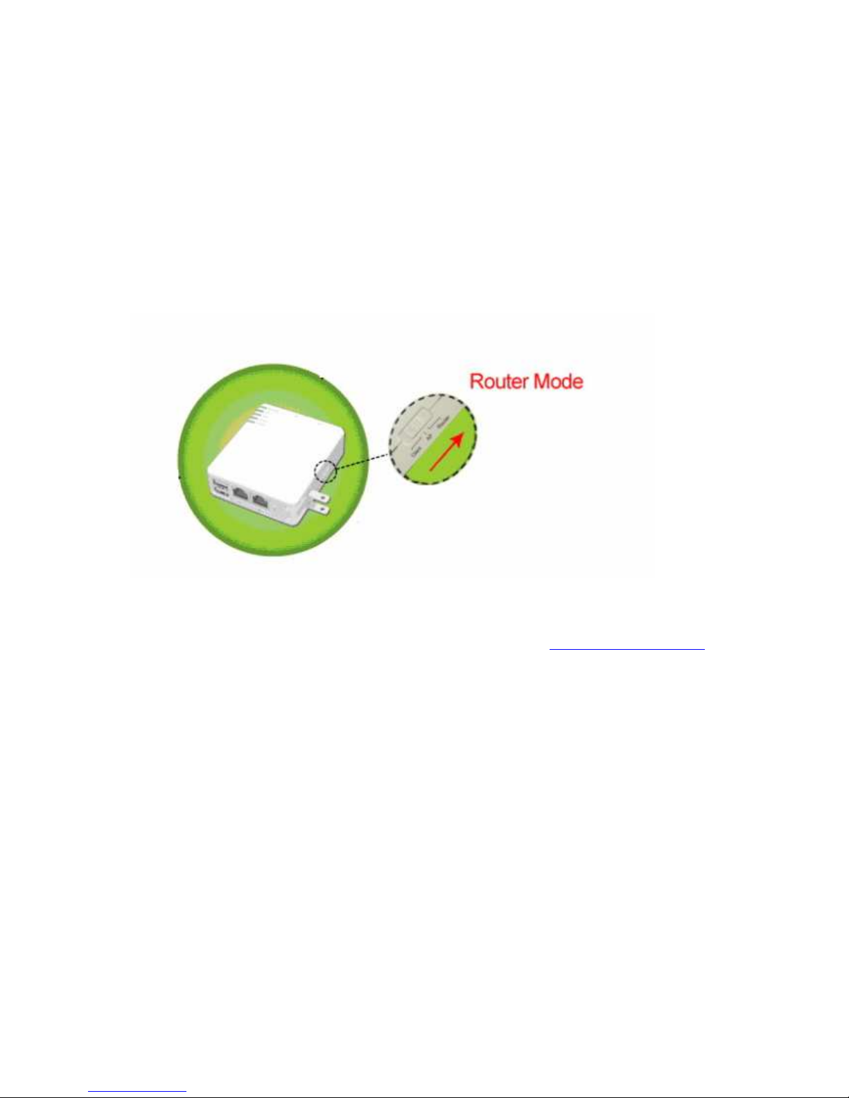
1.1 Router Mode’s Quick Setup Instruction
Please switch the slide to “Router Mode” as the below instruction:
Then please open a Microsoft Internet Explorer, and enter http://192.168.100.1
(Default Gateway) into browser’s blank, then you will see the configuration page
below:
Page 6
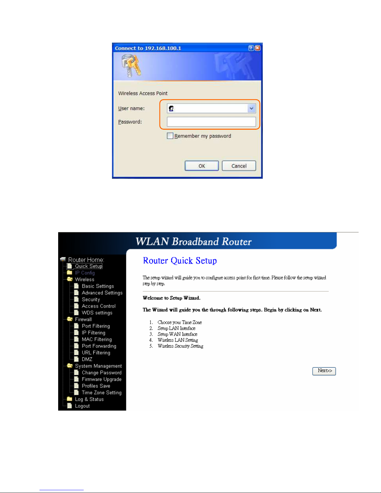
Please input in the blanks, the factory default values for User Name and Password
are “admin” and “admin” (all in lowercase letters); after inputting, please click on
“OK” to enter the homepage as below:
Page 7

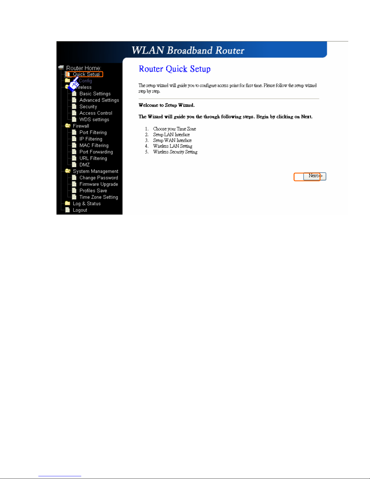
1.2 The Introduction of Router mode’s Quick Setup
After you go to the main page of “Router Quick Setup”, please click on “Next”
right side below, and go to the next page to do each setting step by step:
Page 8
1.2.1 Time Zone Setting
The section provides to change the Time. However, change the router’s date and
time does not affect the date and time on your PCs.
Page 9
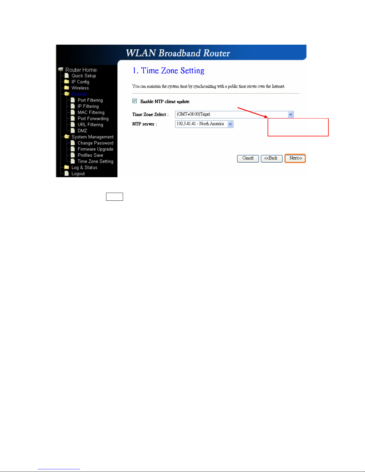
Please click on “Next” button to connect to next step.
1.2.2 LAN Interface Setup
If you are using the Mini Router with multiple PCs on your LAN, please set up this
function for multiple users to connect it. The default LAN IP for R130g is
192.168.100.1.
Please select your
time Zone
Page 10
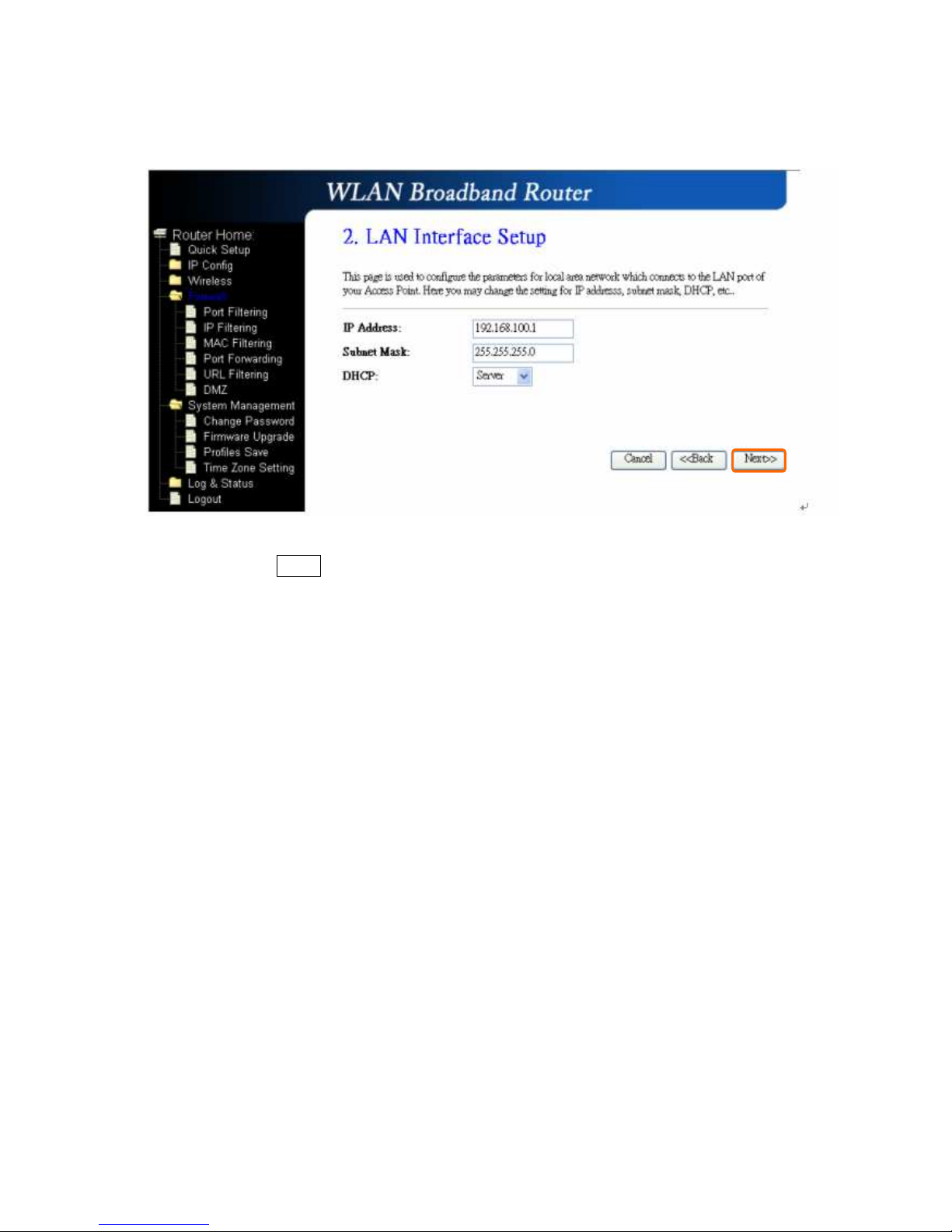
Please click on “Next” button to connect to next step.
1.2.3 WAN Interface Setup
R130g supports 4 connection types to WAN, select one of the WAN connection
modes required by your ISP in below “WAN Access Type” page, the WAN setting
pages will differ depending on what kind of WAN Type you select.
Page 11
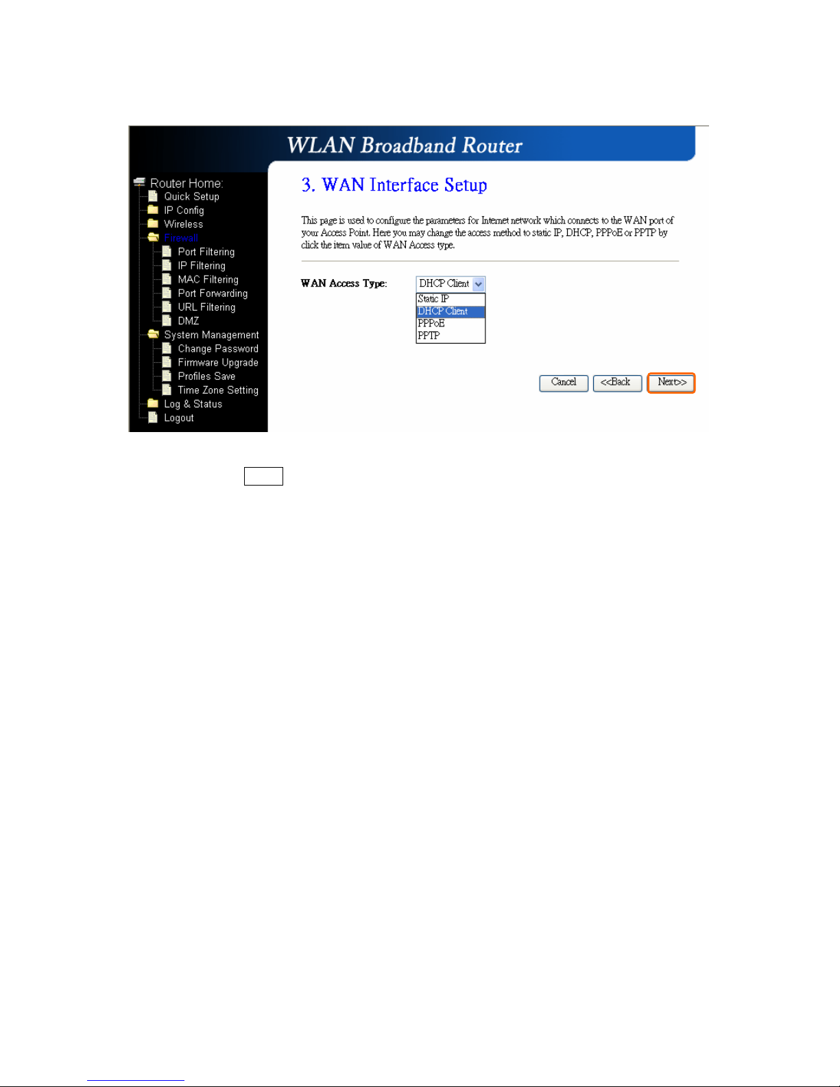
Please click on “Next” button to connect to next step.
1.2.3.1 WAN Interface Setup–
Static IP
Choose Static IP Address if all WAN IP information is provided to you by your ISP.
R330g will not accept the IP address if it is not in this format, and the blanks of
“IP Address”, “Subnet Mask” and “Default Gateway” must be input.
Page 12
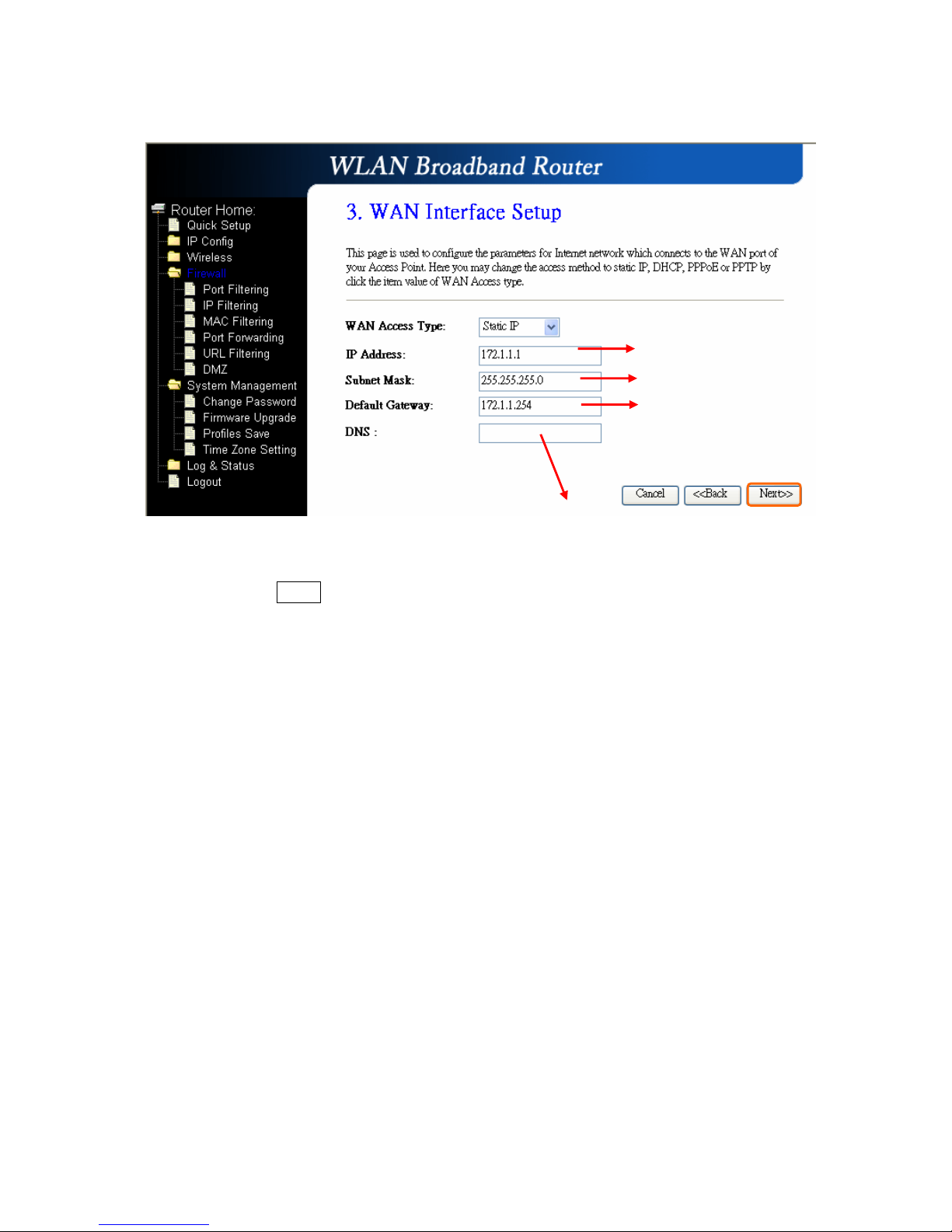
Please click on “Next” button to connect to next step.
1.2.3.2 WAN Interface Setup– DHCP Client
Choose DHCP Client to obtain IP address information automatically from your ISP.
Select this option if your ISP does not give you any IP numbers to use.
Input the data provided
by ISP
Input the data provided
by ISP
Input the data provided
by ISP
DNS also needs to be inputted,,,,otherwise you can use the
domain name.
Page 13
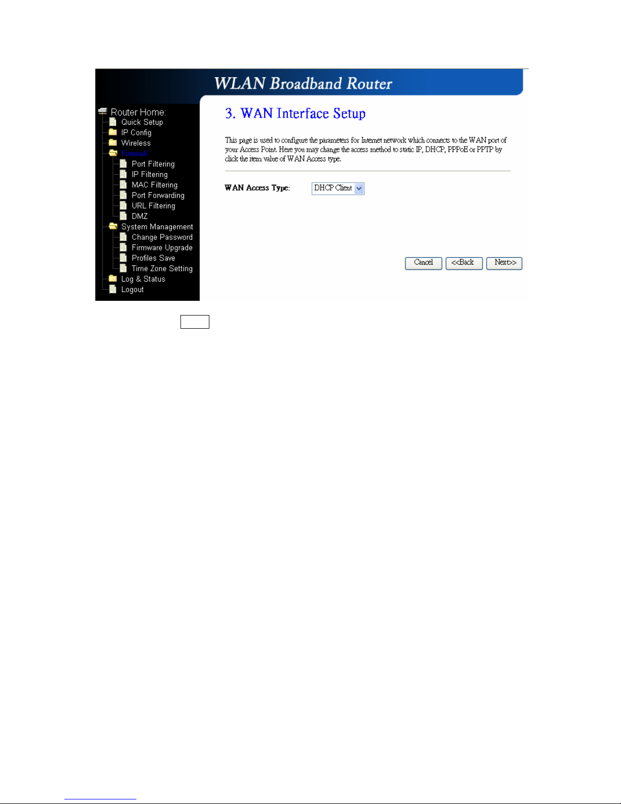
Please click on “Next” button to connect to next step.
1.2.3.3 WAN Interface Setup– PPPoE
If your ISP uses PPPoE connection, your ISP will provide you with a username and
password.
Page 14
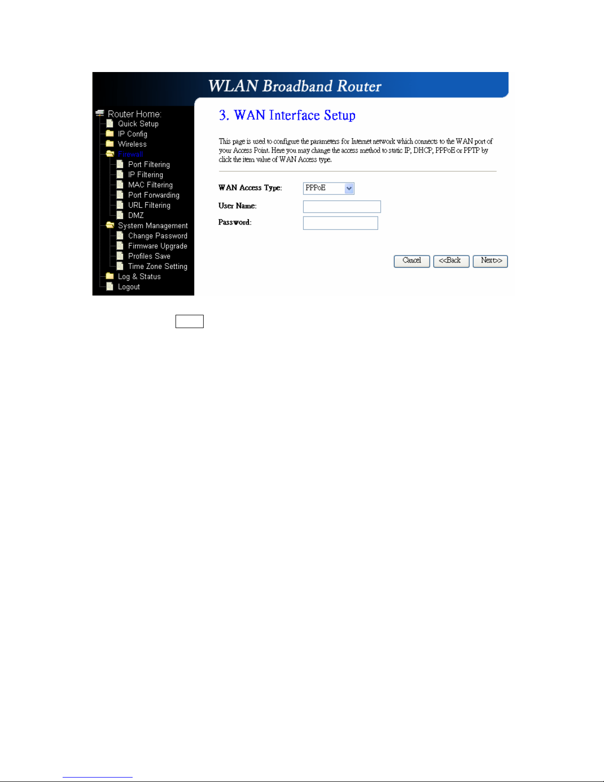
Please click on “Next” button to connect to next step.
1.2.3.4 WAN Interface Setup– PPTP
Some DSL service providers supply a special DSL modem in Europe or Big Pond
Cable in Australia. This kind of modem only supports the PPTP tunnel to access
the Internet; Please enter the account’s information of Account and Password
Page 15
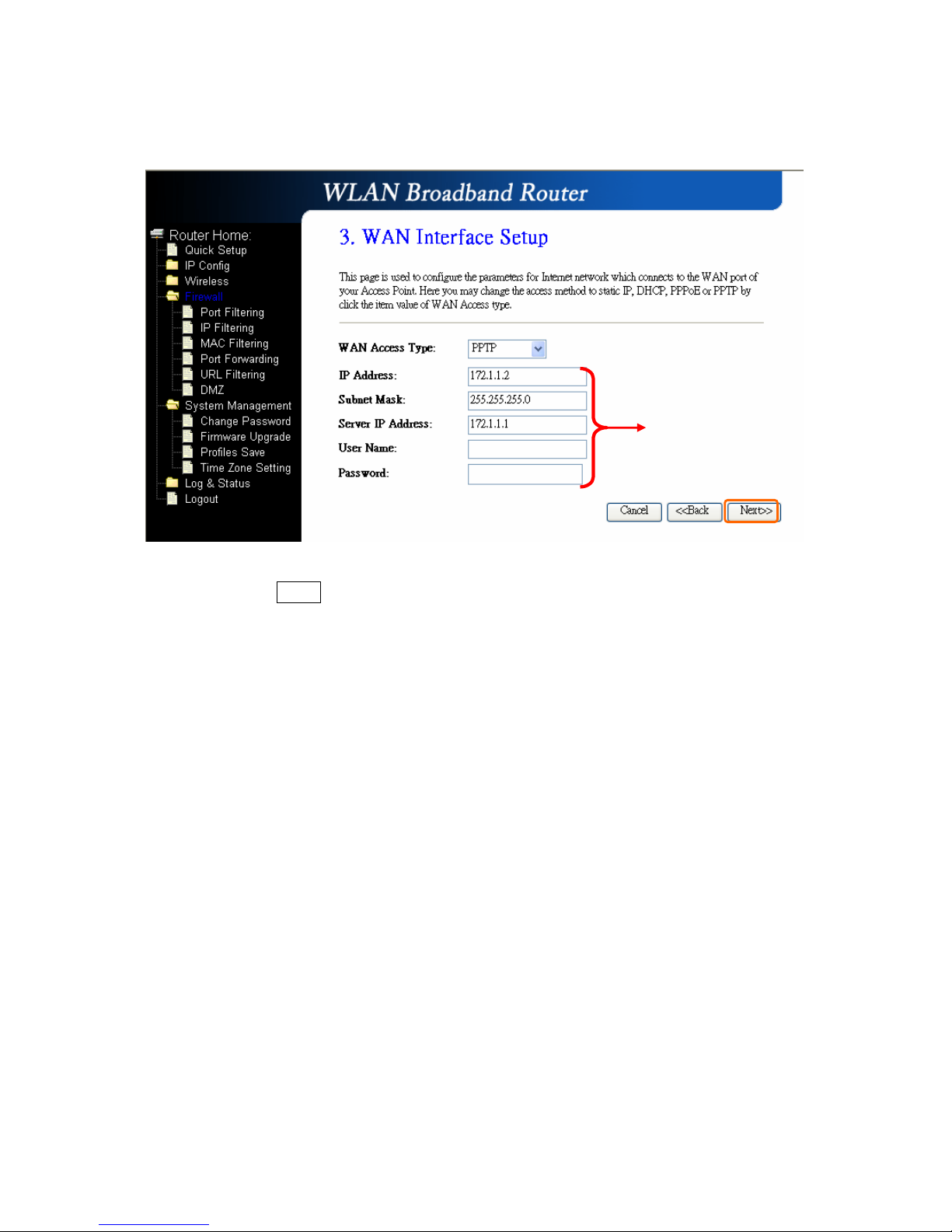
which provided by your ISP.
Please click on “Next” button to connect to next step.
IP Address, Server IP
Address and Subnet Mask are
all input as necessary.
Page 16
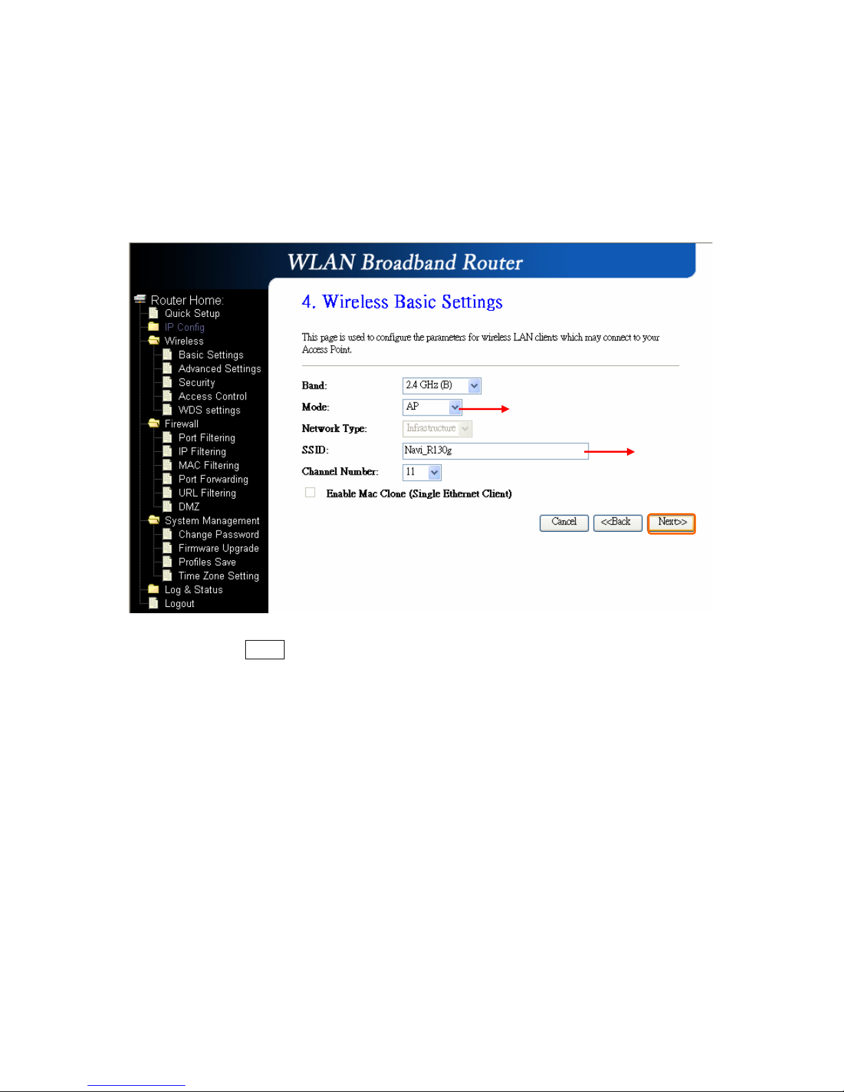
1.2.4 Wireless Basic Settings
The first step of setting up the “Wireless Basic Settings” is to give a name for
SSID, herewith the default name of SSID is Navi_R130g, it’s suggested to use.
Please click on “Next” button to connect to next step.
Select the
suitable
item for you to use.
It’
s suggested to use.
Page 17
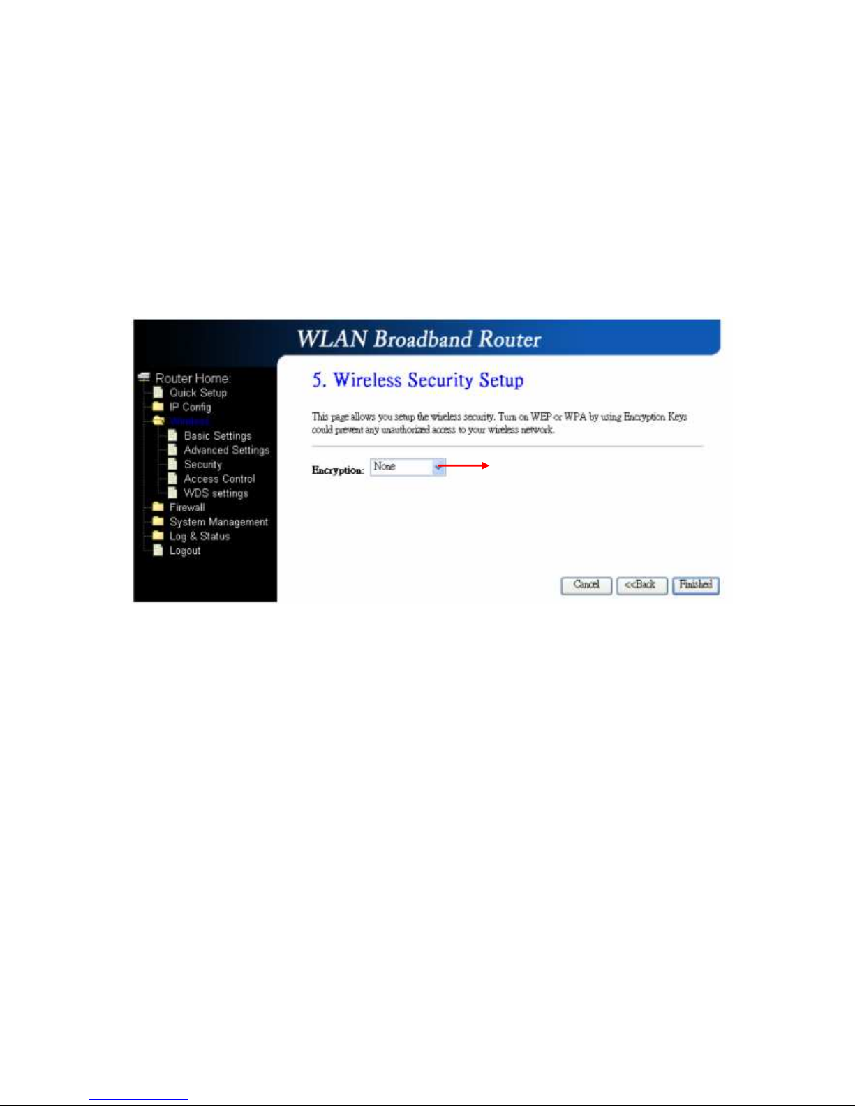
1.2.5 Wireless Security Setup
The “Encryption” item of “Wireless Security Setup” is optional; which means you
can choose it under your demand, herewith it’s divided into two categories of
“WEP” and “WPA”, if you want to protect your transmitting data; you can select it
depended on the level of your request.
Please follow the instruction below to complete “Wireless Security Setup”.
a. Wireless—WEP mode
After you select “WEP”, you will see the picture below:
It’s an optional item.
Page 18
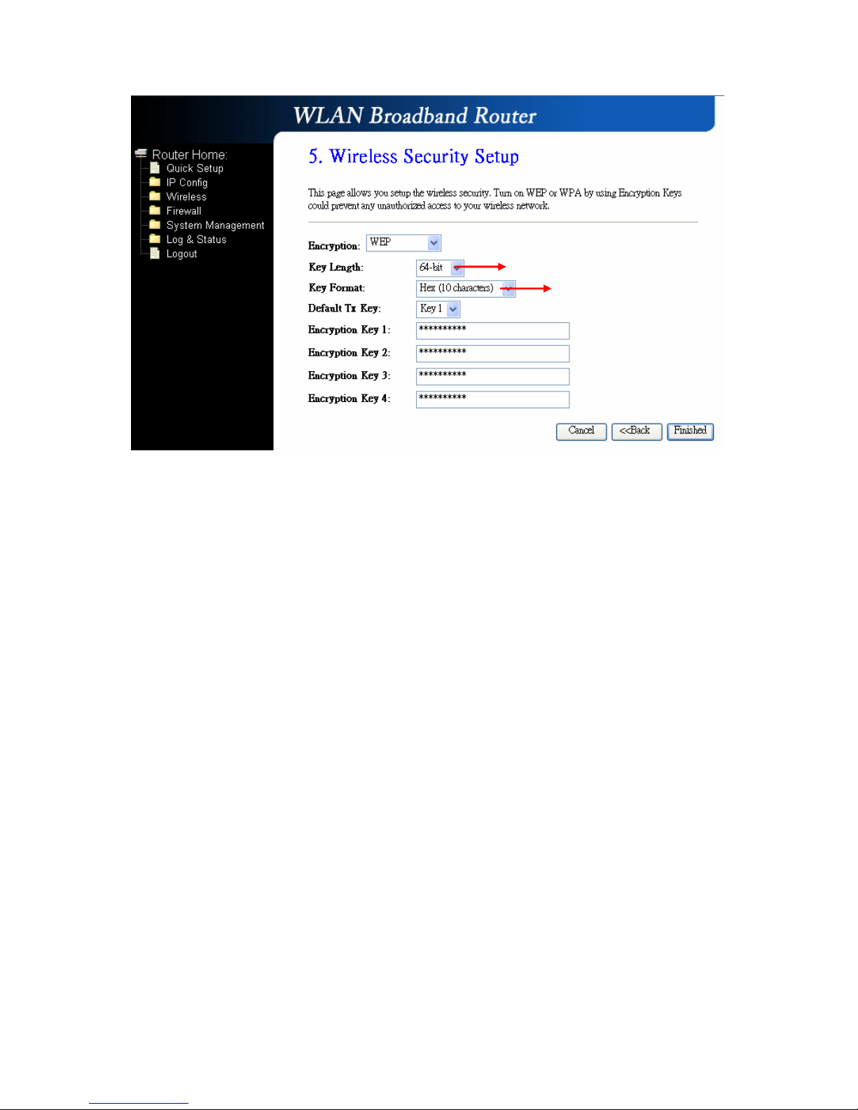
No matter if you selection is either 10 or 26 hexadecimal digits (0~9, a~f, and A~F)
in the pull-down menu bar of “Key Format”; it will be based on whether you select
64-bits or 128-bits in the “Key Length” pull-down menu. After you select it, there
will be 4 “Encryption Keys” generated automatically; please input it with data, such
as: WEP-64bit key: 10 hexadecimal digits (0~9, a~f, and A~F). WEP-128bit key:
26 hexadecimal digits (0~9, a~f, and A~F). As for the “Default Tx key”, it lets you
specify which of the four encryption keys you use to transmit the data on your
wireless LAN.
b. Wireless—WPA mode
The WPA mode is recommended when you want to have better security. Once the
WPA mode is used, the authentication methods of “TKIP” and “AES” will be applied.
WPA (TKIP):
It stands for Temporal Key Integrity Protocol (TKIP), TKIP will verify the
security configuration after your encryption keys are determined.
WPA2 (AES):
It stands for Advanced Encryption Standard (AES), it is a symmetric
128-bitblock data technique, which it works simultaneously on differently
multiple network layers.
It has low level (64-bit) and high level
(128-bit).
It has “10 characters” and “26
characters”; it will be listed under
your selection is low level (64-bit)
or high level (128-bit).
Page 19
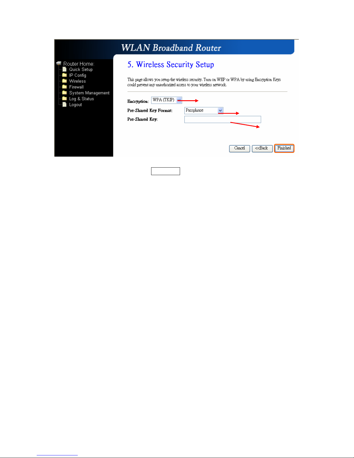
After setting up, please click on Finished” button to connect to next step.
Select it by your request
Please input it as necessary
Please select it under your demand
Page 20
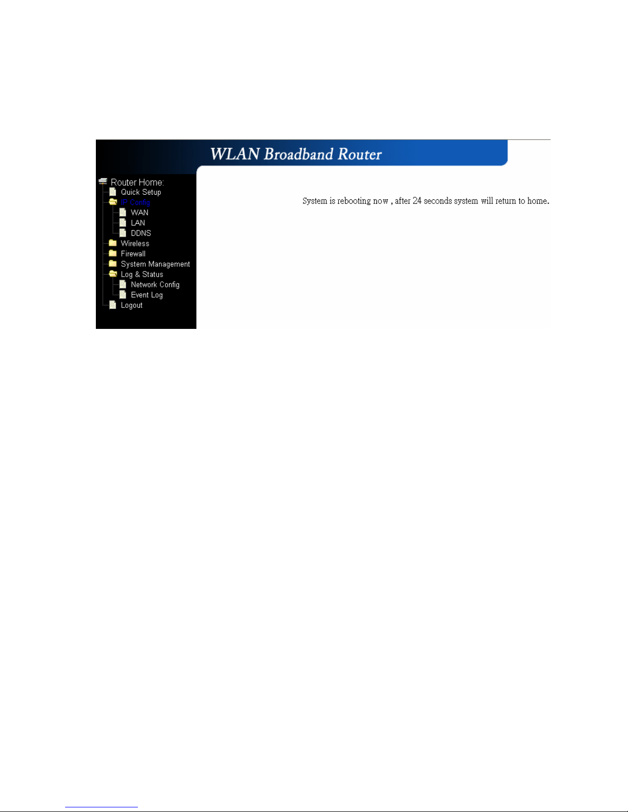
1.2.6 Quick Setup Finish
The Quick Setup has been completed successfully when you see this screen.
The system will be rebooting automatically and goes to the Product’s Diagram
Homepage after 60 seconds.
Page 21
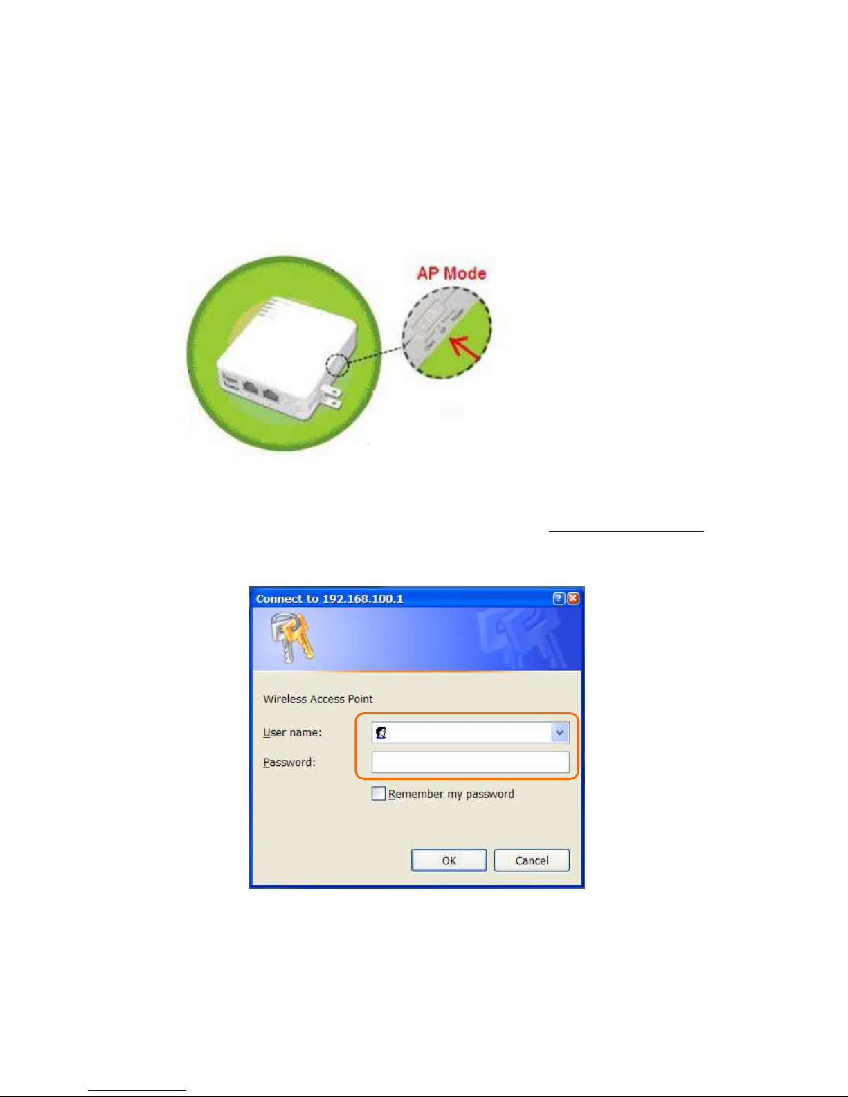
Chapter 2 AP Mode’s Quick Setup
2.1 AP mode’s Configuration
Please switch the slide to “AP Mode” as the below instruction:
Then please open a Microsoft Internet Explorer, and enter http://192.168.100.1
(Default Gateway) into browser’s blank, then you will see the configuration page
below:
Please input in the blanks, the factory default values for User Name and Password
are “admin” and “admin” (all in lowercase letters); after inputting, please click on
“OK” to enter the homepage as below:
Page 22
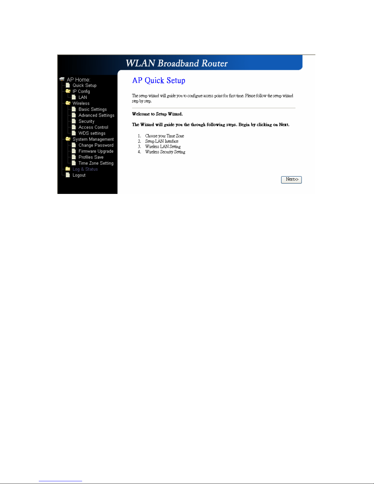
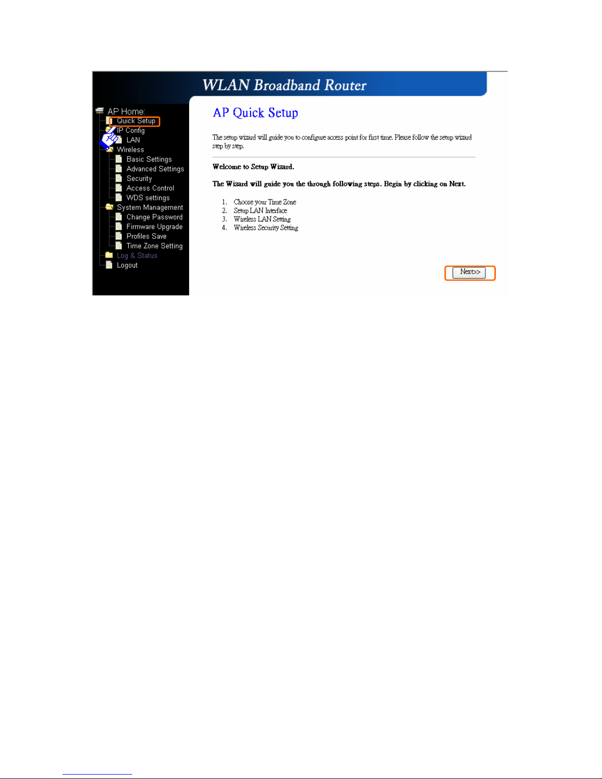
2.2 The Introduction of AP mode’s Quick Setup
After you go to the main page of “AP Quick Setup”, please click on “Next” right
side below, and go to the next page to do each setting step by step:
Page 23
Page 24
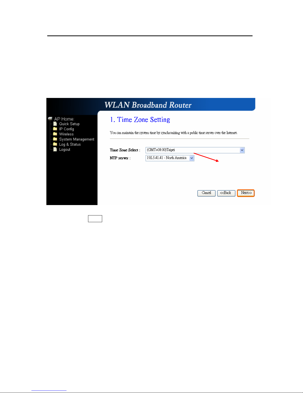
2.2.1 Time Zone Setting
The section provides to change the Time. However, change the router’s date and
time does not affect the date and time on your PCs.
Please click on “Next” button to connect to next step.
Please select your time Zone
Page 25
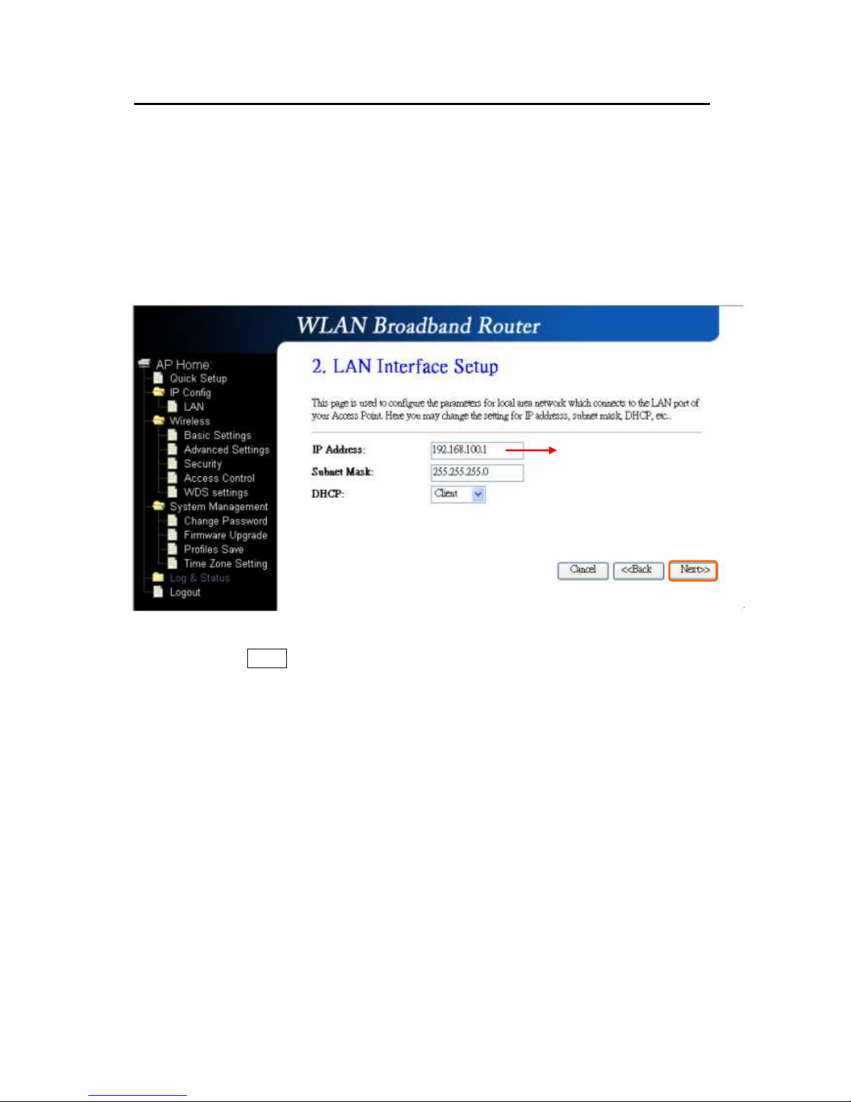
2.2.2 LAN Interface Setup
If you are using the Mini Router with multiple PCs on your LAN, please set up this
function for multiple users to connect it. The default LAN IP for R130g is
192.168.100.1.
Please click on “Next” button to connect to next step.
The default data is suggested to use.
Page 26
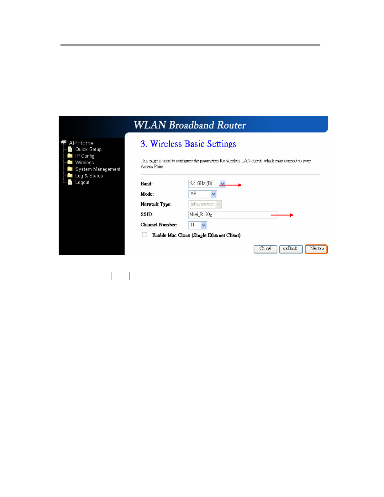
2.2.3 Wireless Basic Settings
The first step of setting up the “Wireless Basic Settings” is to give a name for
SSID, herewith the default name of SSID is Navi_R130g, it’s suggested to use.
Please click on “Next” button to connect to next step.
Select the suitable item for you to use.
It’s suggested to use
Page 27
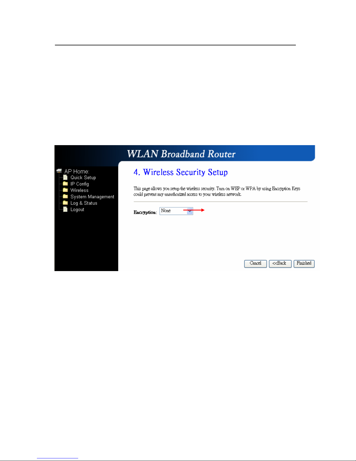
2.2.4 Wireless Security Setup
The “Encryption” item of “Wireless Security Setup” is optional; which means you
can choose it under your demand, herewith it’s divided into two categories of
“WEP” and “WPA”, if you want to protect your transmitting data; you can select it
depended on the level of your request.
Please follow the instruction below to complete “Wireless Security Setup”.
a. Wireless—WEP mode
After you select “WEP”, you will see the picture below:
It’s an optional item.
Page 28
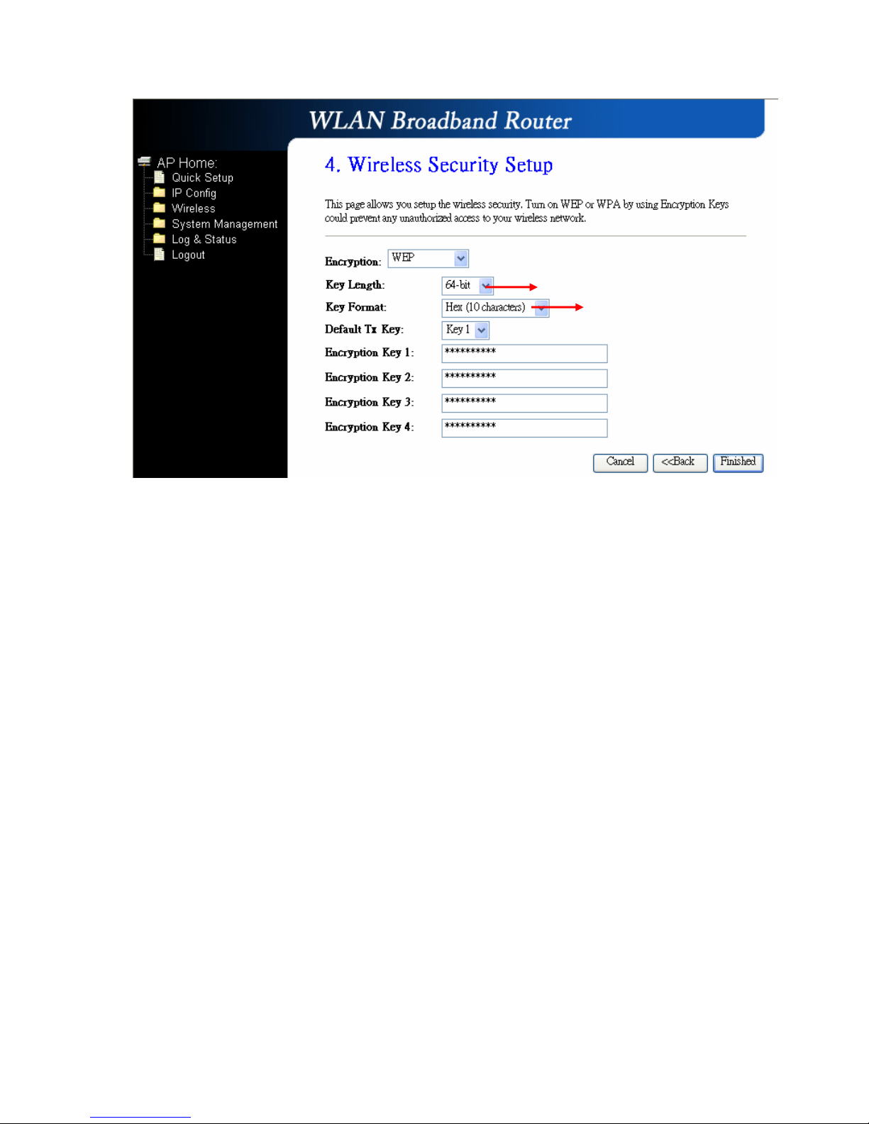
No matter if you selection is either 10 or 26 hexadecimal digits (0~9, a~f, and A~F)
in the pull-down menu bar of “Key Format”; it will be based on whether you select
64-bits or 128-bits in the “Key Length” pull-down menu. After you select it, there
will be 4 “Encryption Keys” generated automatically; please input it with data, such
as: WEP-64bit key: 10 hexadecimal digits (0~9, a~f, and A~F). WEP-128bit key:
26 hexadecimal digits (0~9, a~f, and A~F). As for the “Default Tx key”, it lets you
specify which of the four encryption keys you use to transmit the data on your
wireless LAN.
b. Wireless—WPA mode
The WPA mode is recommended when you want to have better security. Once the
WPA mode is used, the authentication methods of “TKIP” and “AES” will be applied.
WPA (TKIP):
It stands for Temporal Key Integrity Protocol (TKIP), TKIP will verify the
security configuration after your encryption keys are determined.
WPA2 (AES):
It stands for Advanced Encryption Standard (AES), it is a symmetric
128-bitblock data technique, which it works simultaneously on differently
multiple network layers.
It has low level (64-bit) and high level
(128-bit).
It has “10 characters” and “26
characters”; it will be listed under
your selection is low level
(64-bit) or high level (128-bit).
Page 29
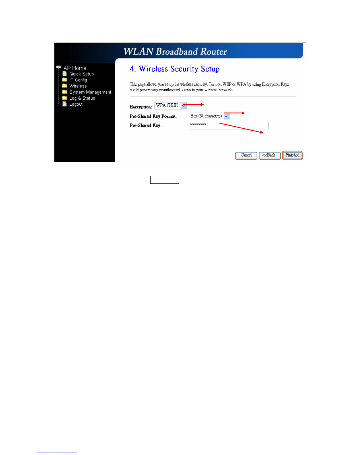
After setting up, please click on Finished” button to connect to next step.
Select it by your request
Please input it as necessary
Please select it under your demand
Page 30
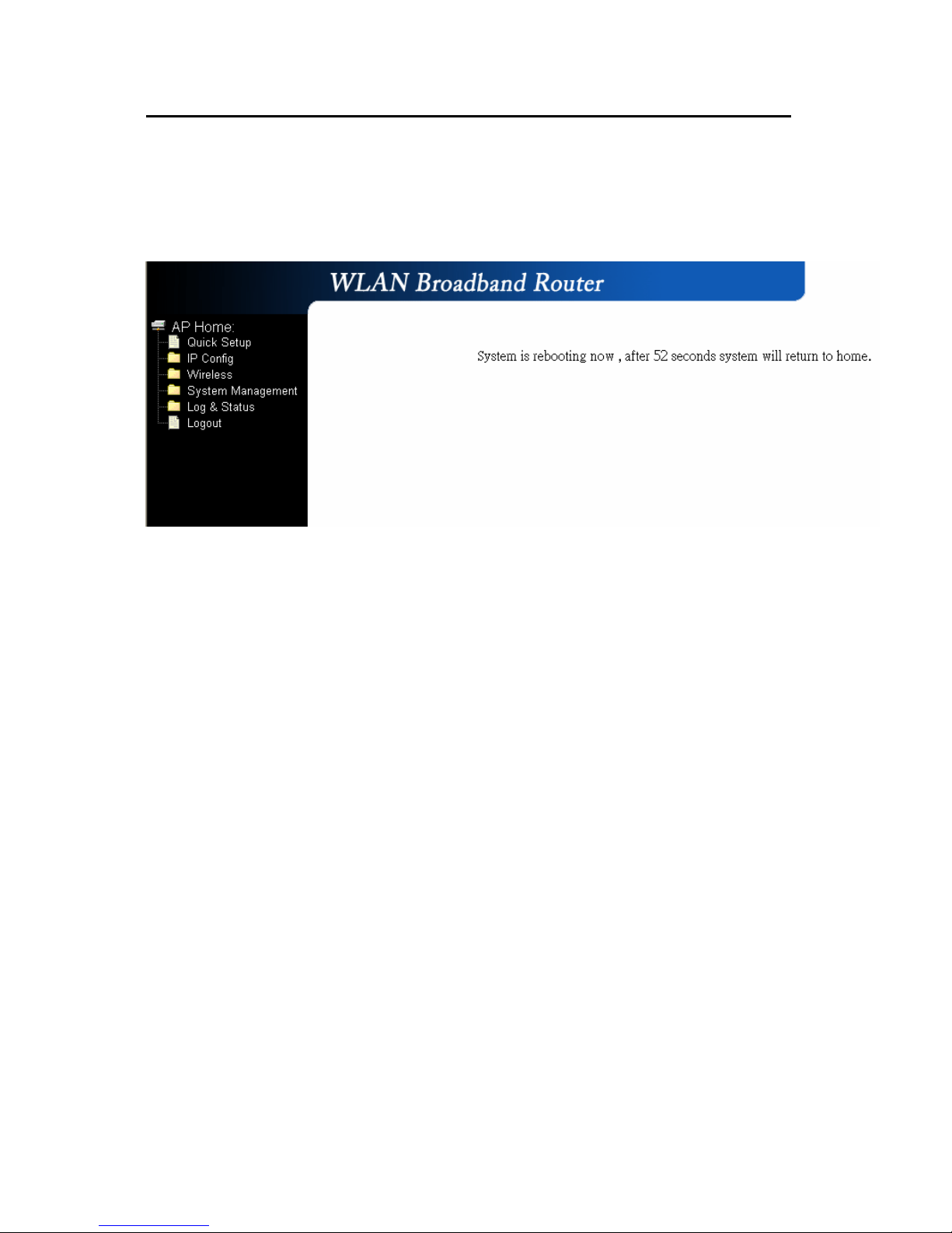
2.2.5 Quick Setup Finish
The Quick Setup has been completed successfully when you see this screen.
The system will be rebooting automatically and goes to the Product’s Diagram
Homepage after 60 seconds.
Page 31
Chapter 3 Client Mode’s Quick Setup
3.1 Client Mode’s Quick Setup Instruction
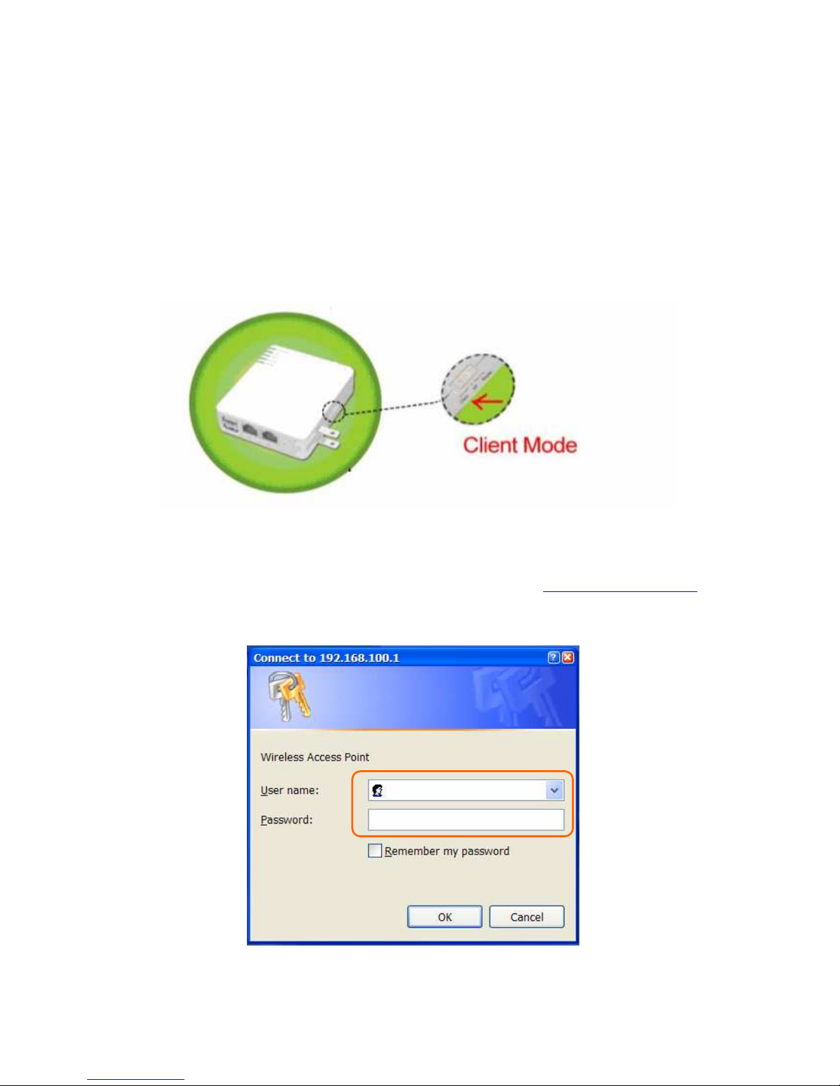
Please switch the slide to “Client Mode” as the below instruction:
Please open a Microsoft Internet Explorer, and enter http://192.168.100.1
(Default Gateway) into browser’s blank, then you will see the configuration page
below:
Page 32
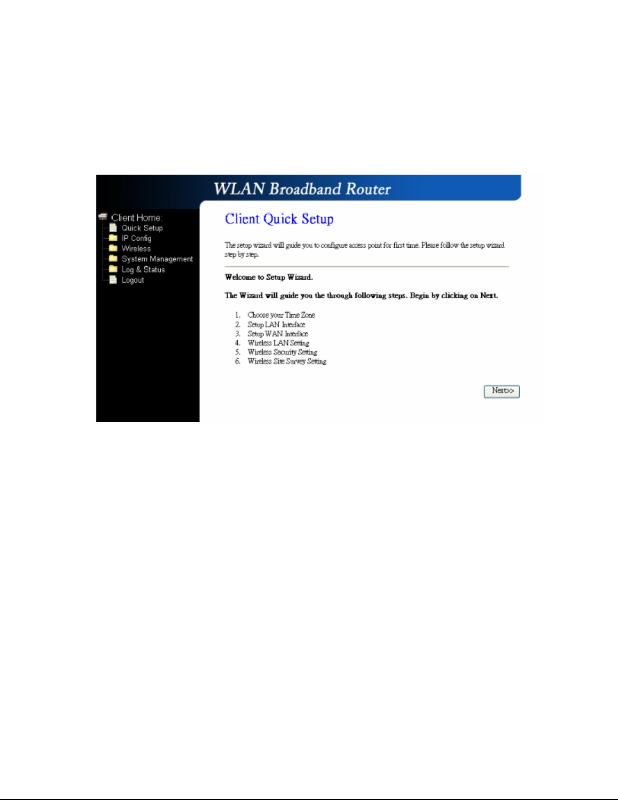
Please input in the blanks, the factory default values for User Name and Password
are “admin” and “admin” (all in lowercase letters); after inputting, please click on
“OK” to enter the Homepage as below:
Page 33
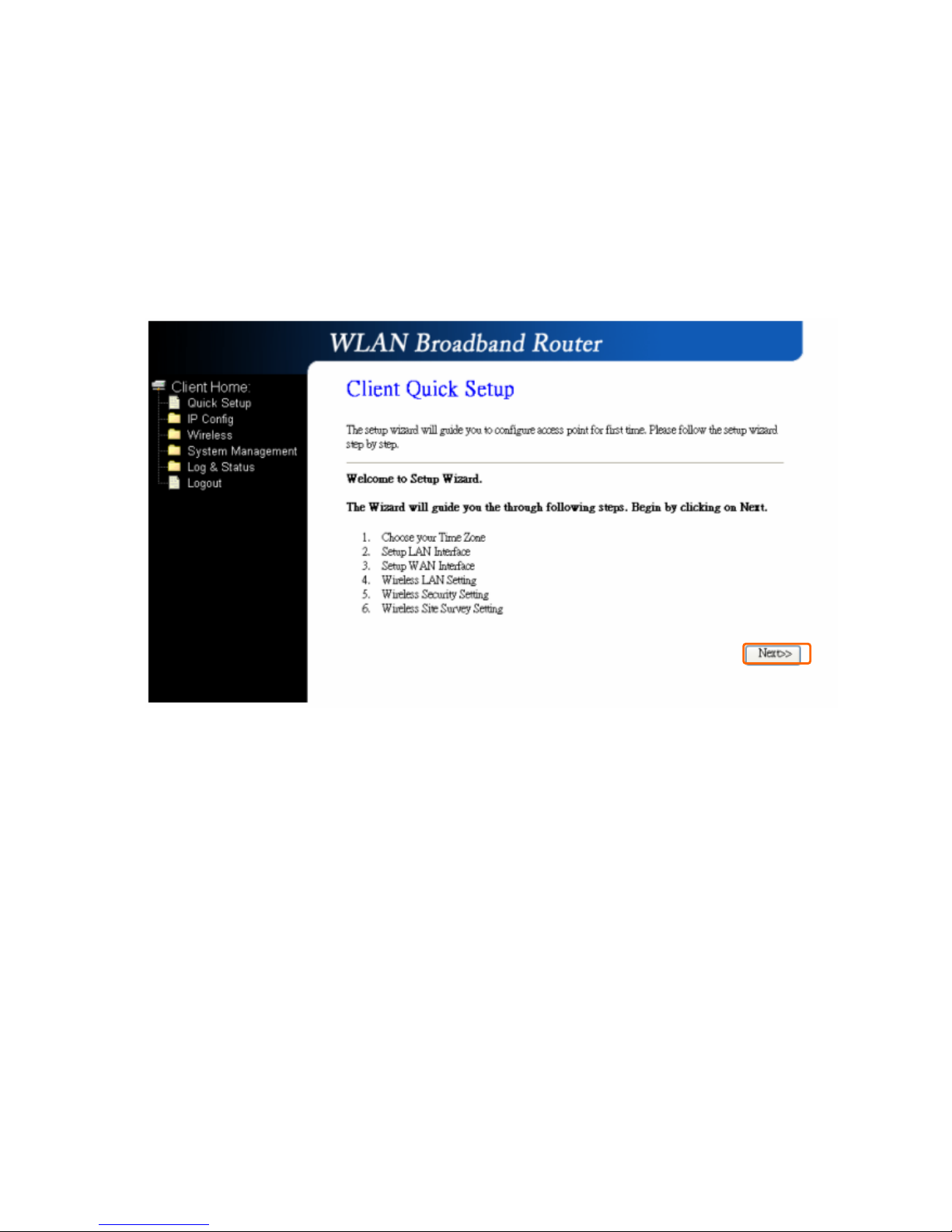
3.2 The Introduction of Client mode’s Quick Setup
After you go to the main page of “Router Quick Setup”, please click on “Next”
right side below, and go to the next page to do each setting step by step:
Page 34
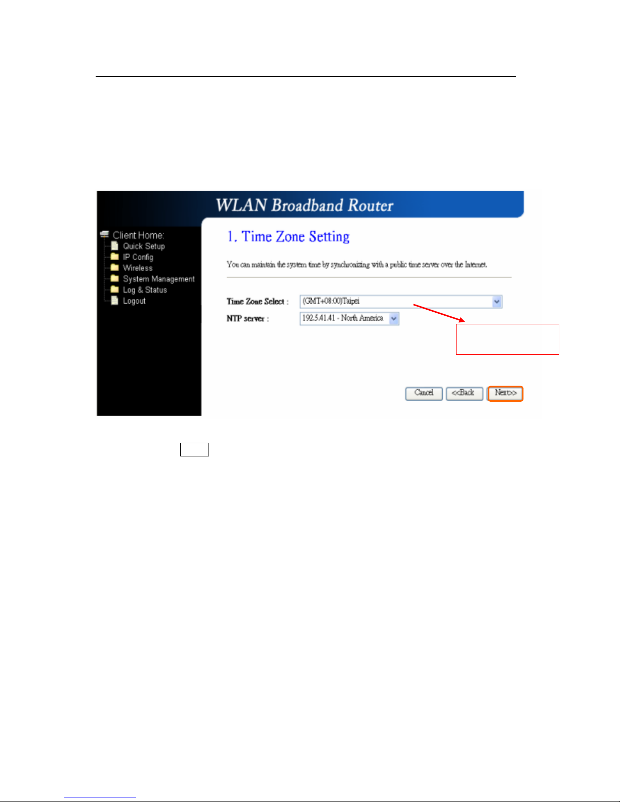
3.2.1 Time Zone Setting
The section provides to change the Time. However, change the router’s date and
time does not affect the date and time on your PCs.
Please click on “Next” button to connect to next step.
Please select your
time Zone
Page 35
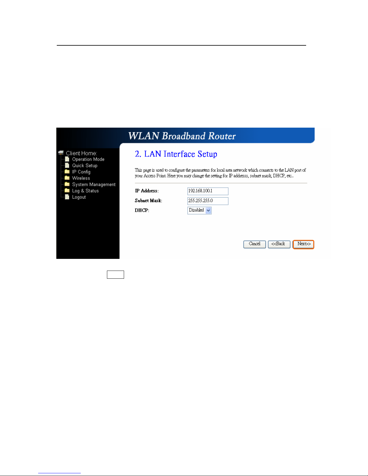
3.2.2 LAN Interface Setup
If you are using the Mini Router with multiple PCs on your LAN, please set up this
function for multiple users to connect it. The default LAN IP for R130g is
192.168.100.1.
Please click on “Next” button to connect to next step.
Page 36
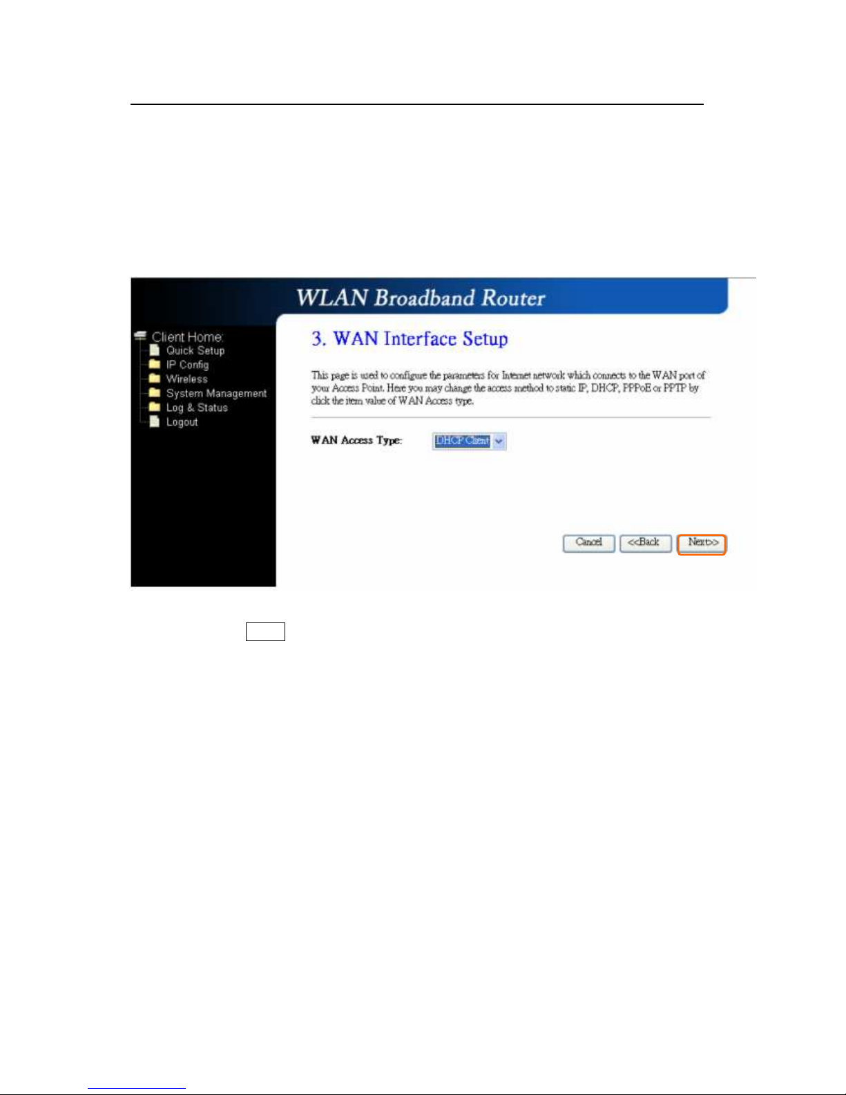
3.2.3 WAN Interface Setup
R130g supports 4 connection types to WAN, select one of the WAN connection
modes required by your ISP in below “WAN Access Type” page, the WAN setting
pages will differ depending on what kind of WAN Type you select.
Please click on “Next” button to connect to next step.
Page 37
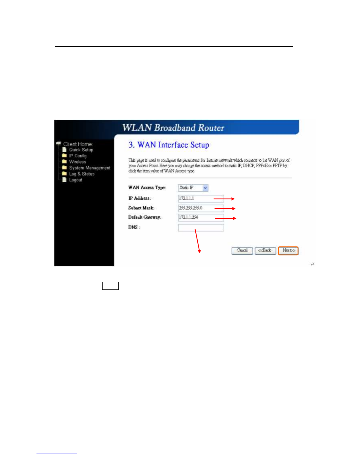
3.2.3.1 WAN Interface Setup–
Static IP
Choose Static IP Address if all WAN IP information is provided to you by your ISP.
R130g will not accept the IP address if it is not in this format, and the blanks of
“IP Address”, “Subnet Mask” and “Default Gateway” must be input.
Please click on “Next” button to connect to next step.
Input the data provided
by ISP
Input the data provided
by ISP
Input the data provided
by ISP
DNS also needs to be inputted,,,,otherwise you can use the
domain name.
Page 38
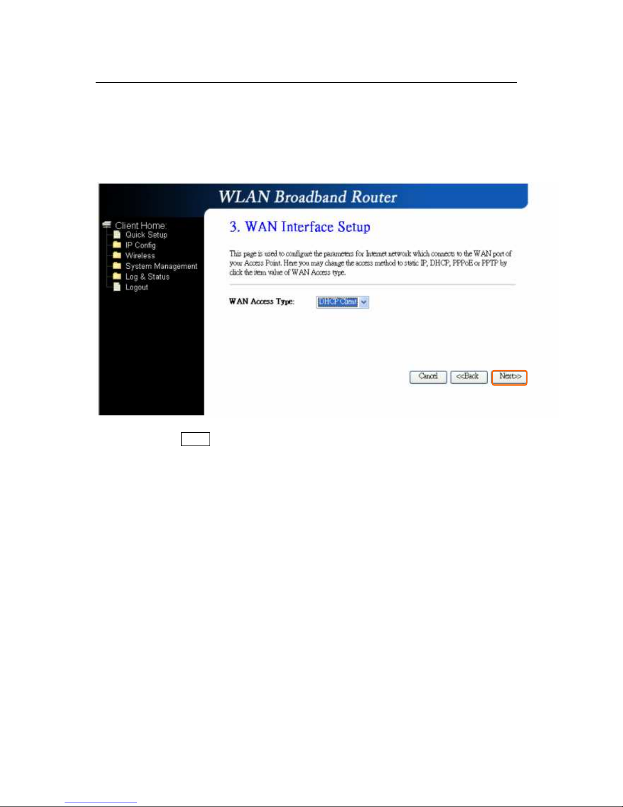
3.2.3.2 WAN Interface Setup– DHCP Client
Choose DHCP Client to obtain IP address information automatically from your ISP.
Select this option if your ISP does not give you any IP numbers to use.
Please click on “Next” button to connect to next step.
Page 39
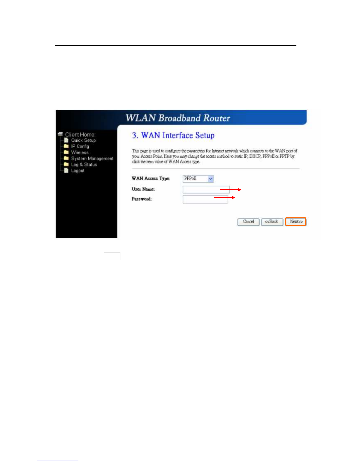
3.2.3.3 WAN Interface Setup– PPPoE
If your ISP uses PPPoE connection, your ISP will provide you with a username and
password.
Please click on “Next” button to connect to next step.
Input it by your ISP provided.
Input it by your ISP provided.
Page 40
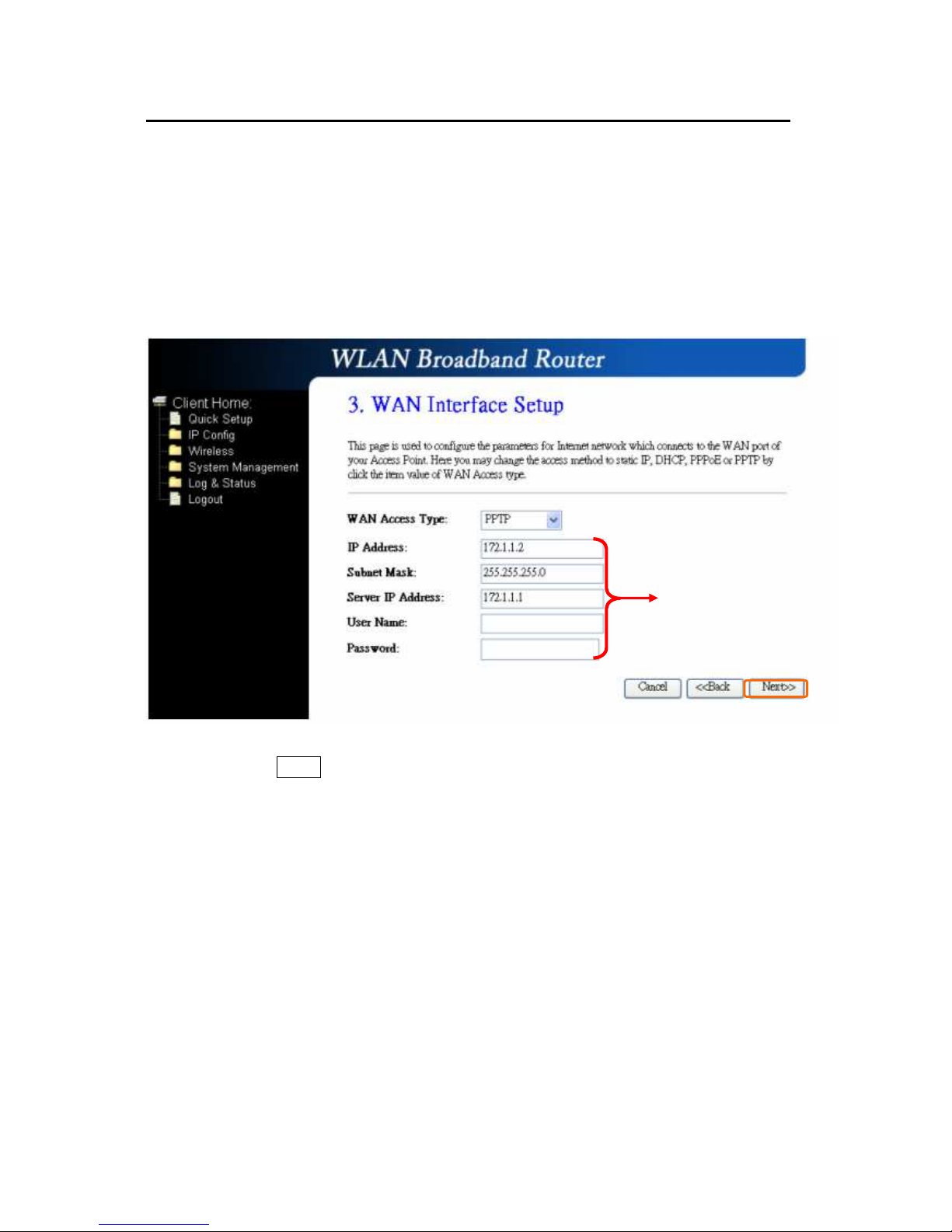
3.2.3.4 WAN Interface Setup– PPTP
Some DSL service providers supply a special DSL modem in Europe or Big Pond
Cable in Australia. This kind of modem only supports the PPTP tunnel to access
the Internet; Please enter the account’s information of Account and Password
which provided by your ISP.
Please click on “Next” button to connect to next step.
IP Address, Server IP
Address and Subnet Mask are
all input as necessary.
Page 41
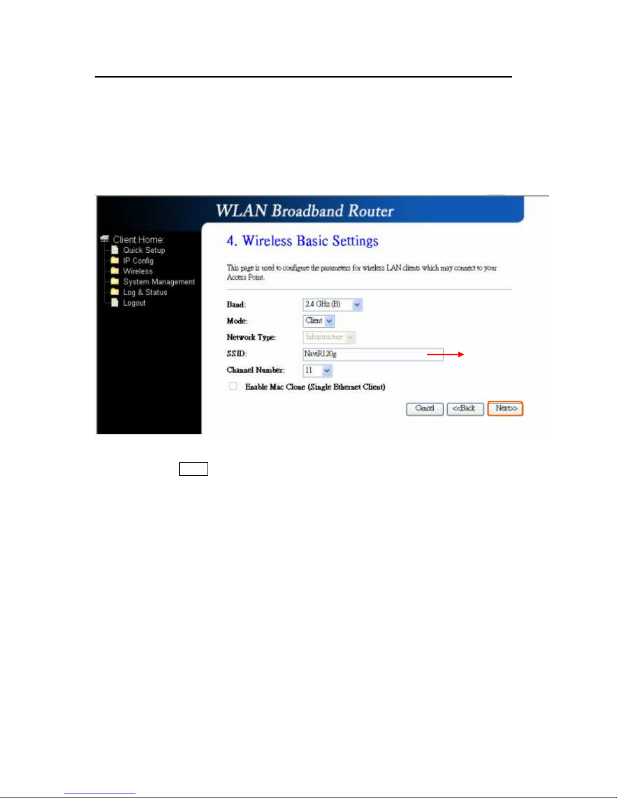
3.2.4 Wireless Basic Settings
This function is used to configure the wireless LAN clients which may connect to
your Access Point; once you connect this Access Point successfully, this name will
be listed automatically in the “SSID”.
Please click on “Next” button to connect to next step.
It’
s up to the Access Point
of wireless LAN clients
that you connect.
Page 42
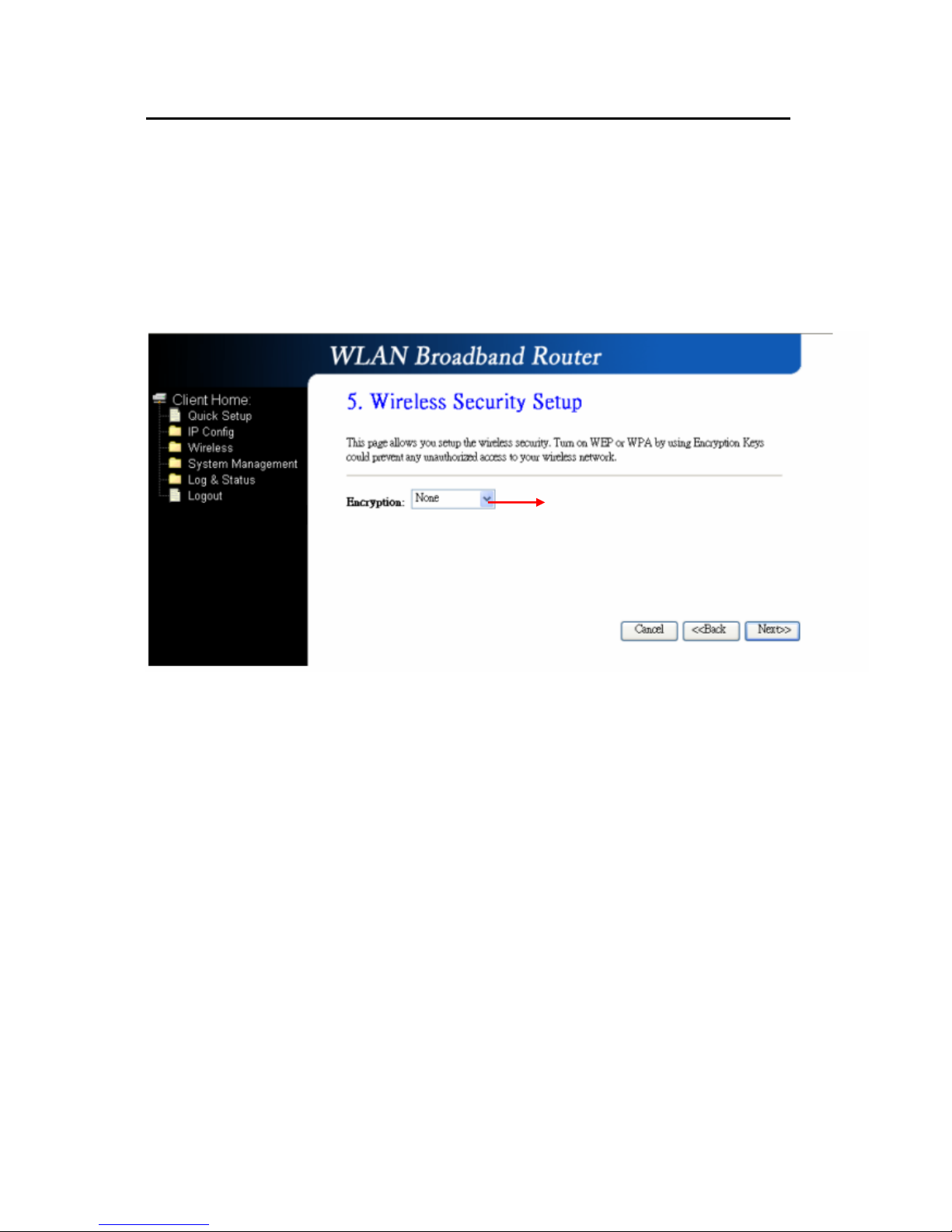
3.2.5 Wireless Security Setup
The “Encryption” item of “Wireless Security Setup” is optional; which means you
can choose it under your demand, herewith it’s divided into two categories of
“WEP” and “WPA”, if you want to protect your transmitting data; you can select it
depended on the level of your request.
Please follow the instruction below to complete “Wireless Security Setup”.
a. Wireless—WEP mode
After you select “WEP”, you will see the picture below:
It’s an optional item.
Page 43
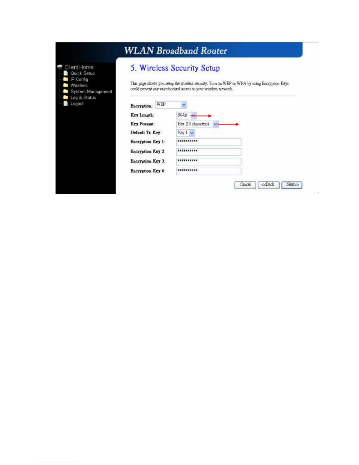
No matter if you selection is either 10 or 26 hexadecimal digits (0~9, a~f, and A~F)
in the pull-down menu bar of “Key Format”; it will be based on whether you select
64-bits or 128-bits in the “Key Length” pull-down menu. After you select it, there
will be 4 “Encryption Keys” generated automatically; please input it with data, such
as: WEP-64bit key: 10 hexadecimal digits (0~9, a~f, and A~F). WEP-128bit key:
26 hexadecimal digits (0~9, a~f, and A~F). As for the “Default Tx key”, it lets you
specify which of the four encryption keys you use to transmit the data on your
wireless LAN.
b. Wireless—WPA mode
The WPA mode is recommended when you want to have better security. Once the
WPA mode is used, the authentication methods of “TKIP” and “AES” will be applied.
WPA (TKIP):
It stands for Temporal Key Integrity Protocol (TKIP), TKIP will verify the
security configuration after your encryption keys are determined.
WPA2 (AES):
It stands for Advanced Encryption Standard (AES), it is a symmetric
128-bitblock data technique, which it works simultaneously on differently
multiple network layers.
It has low level (64-bit) and high level
(128-bit).
It has “10 characters” and “26
characters”; it will be listed under
your selection is low level (64-bit)
or high level (128-bit).
Page 44
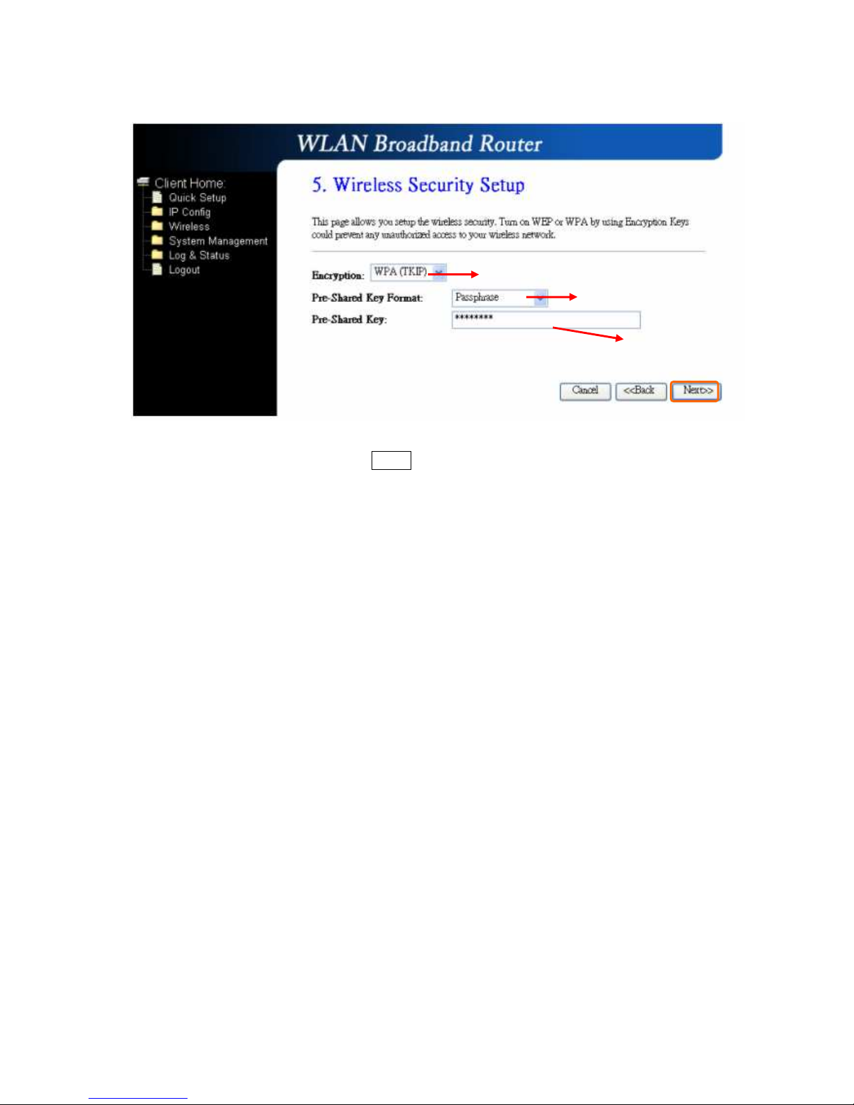
After setting up, please click on “Next” button to connect to next step.
Select it by your request
Please input it as necessary
Please select it under your demand
Page 45
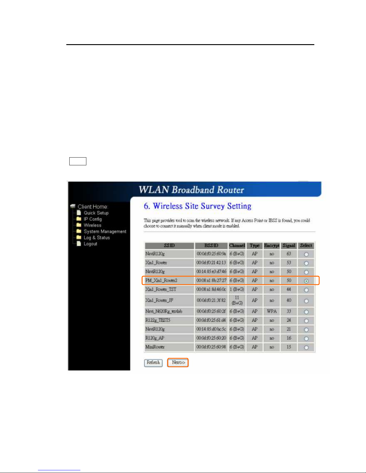
3.2.6 Wireless Site Survey Setting
This function provides you with scanning the wireless network; which
means if any Access Point is found, you could choose to connect it
manually when the client mode is enabled, and after you choose the
desired Access Point; this name will be listed automatically in the “SSID” of
“Wireless Basic Settings” page for you to check, please see the
introduction below:
If you choose the “PM_Xin1_Router2” for the Access Point, and click on
“Next” as below:
Then the system will be rebooting automatically and goes to the Product’s
Diagram Homepage after 60 seconds:
Page 46
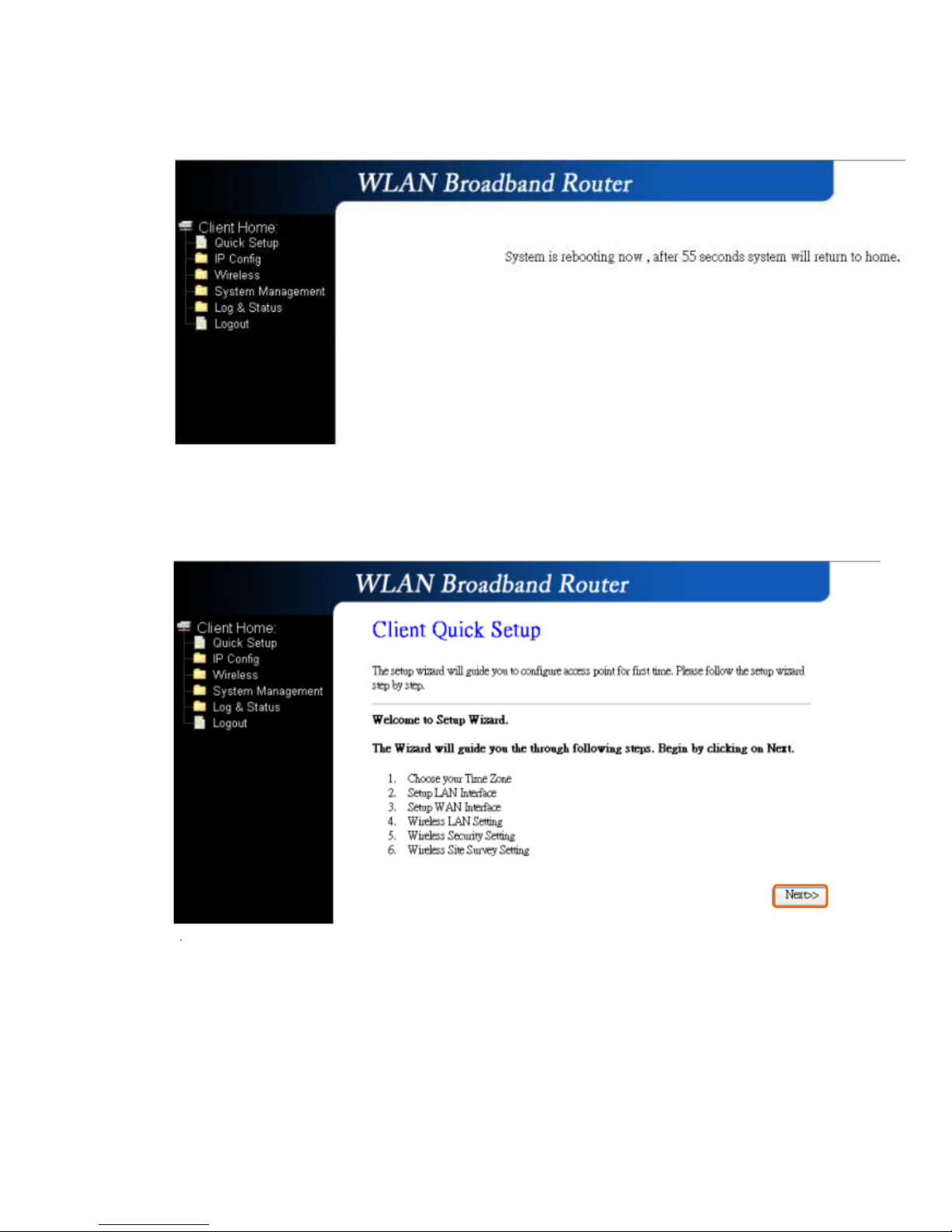
The system goes to the Product’s Diagram Homepage:
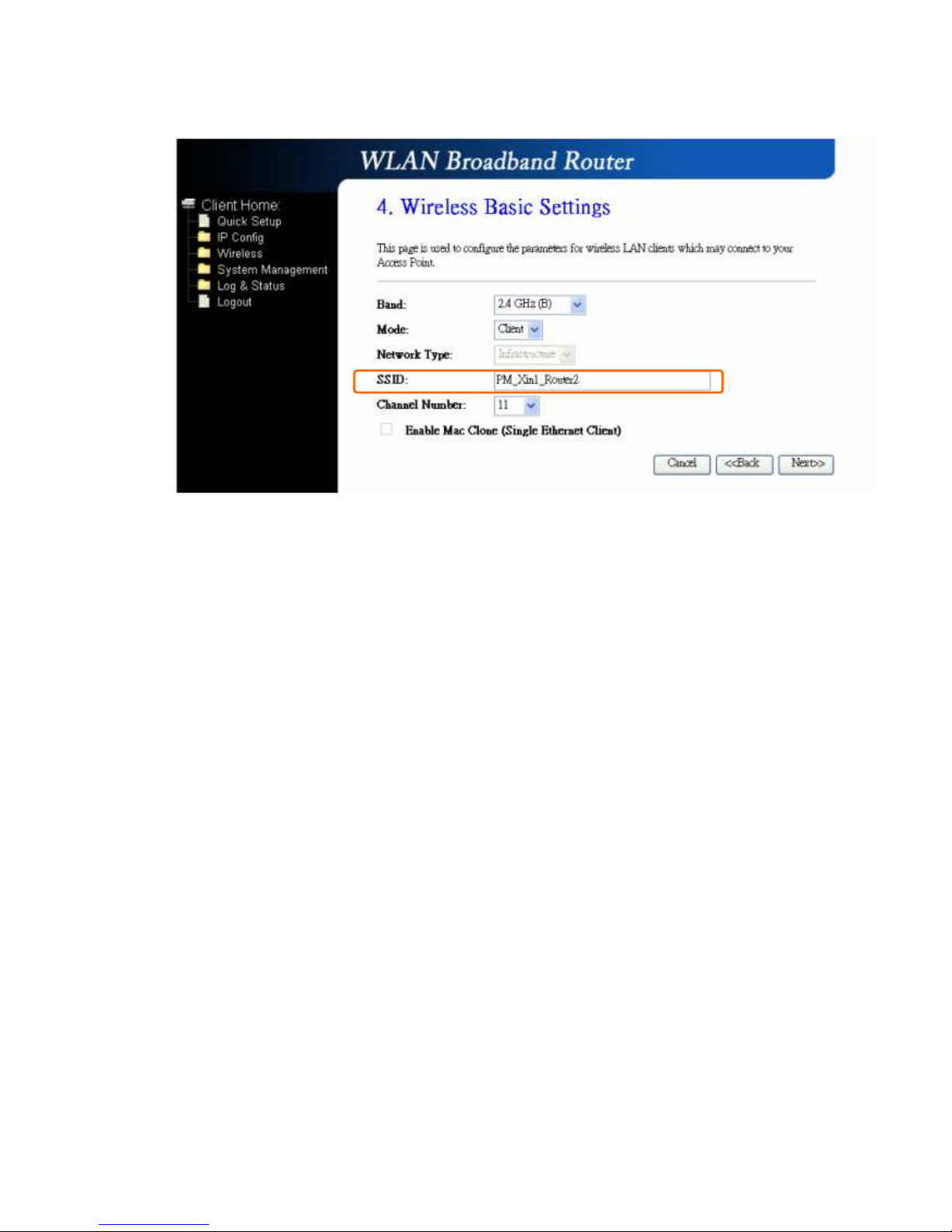
Please go to the “4. Wireless Basic Settings”; and you will see the name
“PM_Xin1_Router2” of Access Point you choose from the “Wireless Site
Survey Setting” is listed in the “SSID” column, which means you may
connect to this Access Points for wireless LAN clients successfully:
Page 47
 Loading...