

NavCom Technology, Inc.
20780 Madrona Avenue
Torrance, California 90503 USA
Tel: +1 310.381.2000
Fax: +1 310.381.2001
sales@navcomtech.com
www.navcomtech.com
P/N: 96-310029-3001
S
Stt
a
arr
U
Uttiill
3
3
0
0
0
0
0
0
UUsseerr GGuuiidde
e

StarUtil 3000 User Guide – Rev G
This page is left blank intentionally

StarUtil 3000 User Guide – Rev G
Table of Contents
Table of Contents ....................................................................................................................... i
List of Tables ............................................................................................................................. x
Notices ...................................................................................................................................... xi
Copyright .............................................................................................................................................. xi
Trademarks .......................................................................................................................................... xi
User Notice ........................................................................................................................................... xi
Limited Warranty .................................................................................................................................. xi
StarFire™ Licensing ............................................................................................................................. xi
USG FAR ............................................................................................................................................. xii
Global Navigation Satellite System ..................................................................................................... xii
Revision History ..................................................................................................................... xiii
Use of This Document ............................................................................................................ xx
Related Documents ................................................................................................................................ xx
SF-3040 GNSS Product User Guide P/N 96-310036-3001 ................................................................ xx
SF-3040 Quick Start Guide P/N 96-310035-3001 ............................................................................... xx
SF-3050 GNSS Product User Guide P/N 96-310034-3001 ................................................................ xx
SF-3050 Quick Start Guide P/N 96-310033-3001 ............................................................................... xx
Sapphire Technical Reference Manual P/N 96-312007-3001............................................................ xx
RINEXUtil User Guide P/N 96-310021-2101...................................................................................... xx
NavCom Release Notes ..................................................................................................................... xxi
Related Standards ................................................................................................................................. xxi
ICD-GPS-200 ..................................................................................................................................... xxi
GLONASS ICD, Version 5.0, 2002 ..................................................................................................... xxi
RTCM-SC-104 .................................................................................................................................... xxi
CMR, CMR+ ....................................................................................................................................... xxi
RINEX ................................................................................................................................................. xxi
QZSS .................................................................................................................................................. xxi
NMEA-0183 ........................................................................................................................................ xxi
Publicly Operated SBAS Signals ........................................................................................................ xxi
RTCA/DO-229D ............................................................................................................................. xxi
WAAS (Wide Area Augmentation System) ................................................................................... xxii
EGNOS (European Geostationary Navigation Overlay Service) .................................................. xxii
MSAS (MTSAT Satellite-based Augmentation System) ............................................................... xxii
GAGAN (GPS Aided Geo Augmented Navigation) ...................................................................... xxii
Chapter 1 Introduction ...................................................................................................... 23
StarUtil 3000 Overview .......................................................................................................................... 23
Features.............................................................................................................................................. 24
File Naming Conventions ................................................................................................................... 25
Save Folder/Files to PC ......................................................................................................................... 25
StarUtil 3000 Main GUI .......................................................................................................................... 26
Window Features ................................................................................................................................ 26
How Output Data Is Polled ............................................................................................................. 26
Refresh Button ............................................................................................................................... 26
Menu Button ................................................................................................................................... 27
Auto Hide Button on the Communication and Input Terminal Windows ........................................ 27
Menu Bar ............................................................................................................................................ 28
Help ................................................................................................................................................ 28
Shortcut Bar ........................................................................................................................................ 29
View/Edit Profile ............................................................................................................................. 29
Data Logging .................................................................................................................................. 29
Connections ................................................................................................................................... 30
Preferences .................................................................................................................................... 31
Receiver Status Bar ............................................................................................................................ 31
Base/Rover Info ............................................................................................................................. 31
i

StarUtil 3000 User Guide – Rev G
Navigation ...................................................................................................................................... 32
Satellites ......................................................................................................................................... 32
Time in UTC ................................................................................................................................... 32
Detailed Views Menu .......................................................................................................................... 32
Post Processing Menu ........................................................................................................................ 33
Data Parsing .................................................................................................................................. 33
Simulation ...................................................................................................................................... 33
Almanac ......................................................................................................................................... 33
RINEX File Processing................................................................................................................... 33
Receiver Setup Menu ......................................................................................................................... 34
StarFire QuickStart ......................................................................................................................... 35
Navigation Modes .......................................................................................................................... 35
Communication Window ..................................................................................................................... 35
Input Terminal ..................................................................................................................................... 36
Chapter 2 Establish Communications ............................................................................. 39
Establish Serial or USB Device Communications ................................................................................. 39
Configure Virtual PC COM Port .......................................................................................................... 41
Install the USB Driver ..................................................................................................................... 41
Verify the Virtual PC Com Port ...................................................................................................... 44
Configure and Establish Bluetooth Communications ......................................................................... 47
Configure Bluetooth via the Input Terminal.................................................................................... 52
Ethernet Communications (SF-3050) .................................................................................................... 53
Configure and Establish Ethernet Communications ........................................................................... 53
Basic Ethernet Configuration: Direct Connection via Static IP Address ............................................ 54
Setup .............................................................................................................................................. 54
Connect SF-3050 to the PC ........................................................................................................... 56
Configure the Radio Modem (SF-3040) ................................................................................................. 58
Request Battery Status (SF-3040) ......................................................................................................... 59
Chapter 3 Firmware ........................................................................................................... 61
Determine If Installed Firmware Is the Most Current ............................................................................. 61
Determine Firmware Versions – Receiver Options Tab/Firmware Info Window ................................... 61
Alternative Method to Determine Firmware Versions ......................................................................... 63
Upload Firmware .................................................................................................................................... 65
PC Baud Rate Requirements for Firmware Upload via Serial Connection ........................................ 65
Upload a Unified Firmware File .......................................................................................................... 66
Upload a Single Firmware File (SF-3050) .......................................................................................... 68
Chapter 4 Geoidal Databases ........................................................................................... 73
Determine If a Geoid Model Is Loaded .................................................................................................. 73
Upload the GGM02 Database ............................................................................................................... 74
Geoid Height Map .................................................................................................................................. 75
GEOIDAL99 Format ........................................................................................................................... 76
Upload a User-Defined Geoid Height Map ......................................................................................... 77
Datum ..................................................................................................................................................... 78
Check Datum ...................................................................................................................................... 79
Reference Frame at Default State ................................................................................................. 79
Command Format and Usage ........................................................................................................ 79
User-Defined Datum ........................................................................................................................... 79
Reference Frame at Non-Default State ......................................................................................... 79
Special Considerations for the RTCM and RTK-Based Solutions ................................................. 80
Chapter 5 Software Options ............................................................................................. 84
How to Purchase Software Options ....................................................................................................... 84
Upload Software Options ....................................................................................................................... 84
Use the Input Terminal to Upload Software Options .......................................................................... 86
RTK Extend ............................................................................................................................................ 86
Enable RTK Extend ............................................................................................................................ 86
Verify RTK Extend Is Active ............................................................................................................... 87
Chapter 6 User Profiles ..................................................................................................... 89
ii

StarUtil 3000 User Guide – Rev G
How User Profiles Work ......................................................................................................................... 89
Profile NONE ......................................................................................................................................... 90
Creating a User Profile ........................................................................................................................... 90
Typical Commands and Parameters in User Profiles ........................................................................ 92
[NAVELEVMASK] .......................................................................................................................... 92
[TRACKINGMODE] ........................................................................................................................ 92
[NAVMEASUSE] ............................................................................................................................ 93
[TRACKINGMODE] and [NAVMEASUSE]..................................................................................... 93
[OUTPUT]NONE,,,-1 ...................................................................................................................... 93
ONCHANGE and ONTIME ............................................................................................................ 93
Position and Raw Data Rates ........................................................................................................ 94
[PDOPLIMIT] .................................................................................................................................. 95
[GEOIDALMODEL]GGM02 ............................................................................................................ 95
[2DNAVMODE] .............................................................................................................................. 96
[L1FALLBACK] ............................................................................................................................... 96
Uploading User Profiles ......................................................................................................................... 96
Avoiding User Profile Loading Errors ................................................................................................. 96
Before Uploading a User Profile ......................................................................................................... 98
Verify Profile in Use ........................................................................................................................ 98
Retrieve User Profile Data from Receiver .......................................................................................... 99
Retrieve User Profile Data from Receiver and Save in Local File ............................................... 100
Retrieve Current Receiver Settings and Save in Local File ......................................................... 101
Upload User Profile from Local File .................................................................................................. 102
Use a Profile Selected from the Profile List ...................................................................................... 103
Edit User Profile ................................................................................................................................ 104
Delete a Selected Profile/All Profiles ................................................................................................ 105
Delete One Profile Stored in the Receiver ................................................................................... 105
Delete All User Profiles Stored in the Receiver ........................................................................... 106
Factory Default Output Messages .................................................................................................... 106
Factory Default NCT Messages ....................................................................................................... 107
Message Descriptions .................................................................................................................. 107
Chapter 7 StarFire Operation ......................................................................................... 109
Description of the StarFire Network ..................................................................................................... 109
RTK Extend .......................................................................................................................................... 109
How to Access the StarFire Service .................................................................................................... 110
StarFire Licensing Terminology ........................................................................................................... 110
Point Radius ..................................................................................................................................... 111
StarFire Satellites ................................................................................................................................. 111
Before Uploading a StarFire License ................................................................................................... 111
How to Upload a StarFire License via Data Cable .............................................................................. 112
How to Upload a StarFire License via the Input Terminal ................................................................... 113
Over the Air StarFire Licensing ............................................................................................................ 114
Over the Air Broadcast ..................................................................................................................... 114
StarFire License Data .......................................................................................................................... 115
StarFire Tab ...................................................................................................................................... 115
Receiver Options Tab ....................................................................................................................... 116
StarFire Licenses Window ........................................................................................................... 117
Cancel License Status Window ................................................................................................... 117
How to Cancel the StarFire License .................................................................................................... 118
StarFire Performance ........................................................................................................................... 118
Confirm StarFire Navigation ............................................................................................................. 118
StarFire Tab ...................................................................................................................................... 119
StarFire Window ........................................................................................................................... 120
Satellite Locations Window .......................................................................................................... 120
Define Satellite Window ............................................................................................................... 122
Setting Up a StarFire Priority Network ............................................................................................. 123
Failed Search ............................................................................................................................... 123
iii

StarUtil 3000 User Guide – Rev G
Reassignment of StarFire Network List ............................................................................................ 123
StarFire Satellites v1.0.1.5 to v2.0.14.0: ...................................................................................... 123
StarFire Satellites v.2.0.15.0 to v3.0.7.0: ..................................................................................... 124
StarFire Satellites v.3.0.12.0 and Later........................................................................................ 124
StarFire QuickStart .............................................................................................................................. 124
Example of QuickStart Use .............................................................................................................. 125
QuickStart State ............................................................................................................................... 126
Chapter 8 RTK Setup ...................................................................................................... 127
Creating an RTK User Profile .............................................................................................................. 127
Example RTK User Profiles .............................................................................................................. 127
Solution Control ................................................................................................................................ 131
[2DNAVMODE] ............................................................................................................................ 131
[ANTENNAHEIGHT] .................................................................................................................... 131
[DYNAMICS] ................................................................................................................................ 132
[L1FALLBACK] ............................................................................................................................. 132
[NAVELEVMASK] ........................................................................................................................ 132
[NAVMEASUSE] .......................................................................................................................... 132
[PDOPLIMIT] ................................................................................................................................ 132
[PRDGPSTIMEOUT] .................................................................................................................... 132
[SOLIDEARTHTIDE] .................................................................................................................... 133
RTK Base Control ............................................................................................................................. 133
[RTKMODE] ................................................................................................................................. 133
[REFNAME] .................................................................................................................................. 134
Set Up Base Position ................................................................................................................... 134
[REFSTNPOS] ............................................................................................................................. 134
[RTKSTATUS1B] ......................................................................................................................... 135
[RTKTIMEOUT] ............................................................................................................................ 135
[RTKFLOATTIMEOUT] ................................................................................................................ 135
[RTKMULTIPATH] ........................................................................................................................ 135
[SELFSURVEY] ........................................................................................................................... 135
Set Up Moving Base Position (Sapphire and SF-3050 only) ....................................................... 135
[ANTALIGN] ................................................................................................................................. 136
[ARLENGTHCONSTR] ................................................................................................................ 136
[EXTRAPBASE] ........................................................................................................................... 136
[FIXBASELINE] ............................................................................................................................ 136
[INCLINECONSTR] ...................................................................................................................... 136
Set Navigation Modes .......................................................................................................................... 136
NCT Legacy Products .......................................................................................................................... 137
SF-3040 Radio Modem ........................................................................................................................ 138
Configure the Radio Settings (SF-3040) .......................................................................................... 138
Retrieve Current Radio Settings (SF-3040) ..................................................................................... 139
Chapter 9 Display of Positioning Performance ............................................................. 141
Dashboard ........................................................................................................................................... 141
PVT ................................................................................................................................................... 142
Velocity & Headings ......................................................................................................................... 142
Sky Plot............................................................................................................................................. 142
StarFire ............................................................................................................................................. 142
Alerts ................................................................................................................................................. 143
PVT Tab ............................................................................................................................................... 143
PVT ................................................................................................................................................... 143
Navigation Status ............................................................................................................................. 144
Antenna Off-Set ................................................................................................................................ 145
Solid Earth Tide ................................................................................................................................ 145
Requirements for Output of SET Corrections .............................................................................. 146
Velocity ............................................................................................................................................. 146
Error Estimates ................................................................................................................................. 147
Solution Plot ..................................................................................................................................... 148
iv

StarUtil 3000 User Guide – Rev G
Menu Options ............................................................................................................................... 148
Channel Status Tab ............................................................................................................................. 149
Description of Data ........................................................................................................................... 150
Manual Selection of SBAS PRN via the Input Terminal ................................................................... 151
MEAS1B Tab ....................................................................................................................................... 151
Description of Data ....................................................................................................................... 152
GPS/SBAS ................................................................................................................................... 152
GLONASS .................................................................................................................................... 153
Sky Plot Tab ......................................................................................................................................... 153
View Raw Data Tab ............................................................................................................................. 154
NMEA Tab ........................................................................................................................................... 155
How to Schedule NMEA Messages ................................................................................................. 155
Chapter 10 Data Logging .................................................................................................. 157
Logging Data to a PC ........................................................................................................................... 157
Configure Logging Options ............................................................................................................... 157
Logging Data to the SF-3050 Internal Memory Device or to the SF-3040 Removable SD Card ..... 158
Scheduling Messages .................................................................................................................. 159
Logging Data to a USB Flash Drive via a USB Host Cable (SF-3050) ............................................ 160
Setup ............................................................................................................................................ 161
Downloading Data from Internal Memory to a PC (SF-3050) .............................................................. 161
Chapter 11 Post Processing ............................................................................................. 163
Data Parsing ........................................................................................................................................ 163
Simulation ............................................................................................................................................ 164
Almanac ............................................................................................................................................... 165
RINEX File Processing ........................................................................................................................ 166
File I/O .............................................................................................................................................. 167
RINEX File Naming Conventions ................................................................................................. 168
User Input ......................................................................................................................................... 168
Options ............................................................................................................................................. 169
GPS Week Number ...................................................................................................................... 170
GPS Time ..................................................................................................................................... 170
Execution and Progress ................................................................................................................... 172
Chapter 12 1PPS/Events ................................................................................................... 173
Configuration ........................................................................................................................................ 174
A NCT Solid Earth Tide (SET) Message Format .............................................................. 175
v

StarUtil 3000 User Guide – Rev G
List of Figures
Figure 1: NavCom Folder ..........................................................................................................25
Figure 2: StarUtil 3000 Main GUI ..............................................................................................26
Figure 3: Refresh Button ...........................................................................................................27
Figure 4: Menu Button ...............................................................................................................27
Figure 5: Auto Hide Button ........................................................................................................27
Figure 6: Input Terminal Window Hidden ..................................................................................27
Figure 7: Cursor on Tab Opens Hidden Window .......................................................................28
Figure 8: StarUtil Help Menu .....................................................................................................28
Figure 9: About StarUtil 3000 ....................................................................................................28
Figure 10: Shortcut Bar .............................................................................................................29
Figure 11: Save/Load/Delete User Profile .................................................................................29
Figure 12: Configure Logging Options .......................................................................................30
Figure 13: Port Configuration – COM Port .................................................................................31
Figure 14: Receiver Status Bar .................................................................................................31
Figure 15: Rover Info ................................................................................................................31
Figure 16: Navigation ................................................................................................................32
Figure 17: Satellites ..................................................................................................................32
Figure 18: Time in UTC .............................................................................................................32
Figure 19: Detailed Views Menu ...............................................................................................32
Figure 20: Post Processing Menu .............................................................................................33
Figure 21: Data Parsing and Simulation ....................................................................................34
Figure 22: Receiver Setup Menu ...............................................................................................34
Figure 23: StarFire QuickStart ...................................................................................................35
Figure 24: Set Navigation Modes ..............................................................................................35
Figure 25: Communication Window – Valid Connection ............................................................36
Figure 26: Communication Window – Connection at Incorrect Baud Rate .................................36
Figure 27: Input Terminal ..........................................................................................................37
Figure 28: Input Terminal – Confirmation ..................................................................................37
Figure 29: Connections Button ..................................................................................................39
Figure 30: Port Configuration ....................................................................................................40
Figure 31: Communication Window – Valid Connection ............................................................41
Figure 32: Communication Window – Connection at Incorrect Baud Rate .................................41
Figure 33: Found New Hardware Wizard/Install Software .........................................................42
Figure 34: Found New Hardware Wizard/Choose Your Search and Installation Options ...........42
Figure 35: NavCom/Utilities/StarUtil 3000/StarUtil 3000 Application ..........................................43
Figure 36: Software Installation Warning Message ...................................................................43
Figure 37: Completing the Found New Hardware Wizard ..........................................................44
Figure 38: My Computer/Properties ..........................................................................................44
Figure 39: System Properties/Hardware Tab/Device Manager Button .......................................45
Figure 40: Device Manager .......................................................................................................46
Figure 41: My Bluetooth Places\Search for devices in range.....................................................47
Figure 42: My Bluetooth Places\Entire Bluetooth Neighborhood ...............................................48
Figure 43: Bluetooth Serial Port Icon for Selected Receiver ......................................................48
Figure 44: Bluetooth Virtual COM Port Connection Established ................................................49
Figure 45: Bluetooth Virtual COM Port Connection Confirmed ..................................................50
Figure 46: Bluetooth Properties .................................................................................................50
Figure 47: Port Configuration – Bluetooth Settings ....................................................................51
Figure 48: Input Terminal – PING Command and Response.....................................................52
Figure 49: Local Area Connection .............................................................................................55
Figure 50: Internet Protocol .......................................................................................................56
Figure 51: Ethernet Port Configuration ......................................................................................57
vi

StarUtil 3000 User Guide – Rev G
Figure 52: Receiver Setup/Configure SF-3040 Radio................................................................58
Figure 53: SF-3040 Radio Configuration and Status .................................................................59
Figure 54: Receiver Setup/Monitor SF-3040 Batteries ..............................................................60
Figure 55: SF-3040 Battery Configuration And Status ...............................................................60
Figure 56: Receiver Options......................................................................................................61
Figure 57: Firmware Window -- Example of Installed Firmware .................................................62
Figure 58: Firmware Folder Contents ........................................................................................62
Figure 59: Comparing Current and Installed Firmware ..............................................................63
Figure 60: Input Terminal ..........................................................................................................63
Figure 61: Version Command ...................................................................................................64
Figure 62: Example of Installed Firmware .................................................................................64
Figure 63: Comparing Current & Installed Firmware .................................................................64
Figure 64: Receiver Options Tab ..............................................................................................66
Figure 65: File Upload – Unified File Loader Option ..................................................................66
Figure 66: Firmware Folder and Contents .................................................................................66
Figure 67: Ready to Downline Load File....................................................................................67
Figure 68: Finished with All Downline Loads .............................................................................68
Figure 69: File Upload – Receiver Firmware .............................................................................68
Figure 70: Load Receiver Firmware .......................................................................................... 69
Figure 71: Firmware Folder Contents ........................................................................................69
Figure 72: Settings for GNSS Firmware ....................................................................................70
Figure 73: Settings for PWRIO Firmware ..................................................................................70
Figure 74: Progress [Load Firmware] Dialog Box ......................................................................71
Figure 75: PVT – GEOID ..........................................................................................................73
Figure 76: Input Terminal – [GGM02STATUS] Command and Response .................................74
Figure 77: Receiver Options......................................................................................................74
Figure 78: File Upload – Load GGM02 ......................................................................................74
Figure 79: Load Grace Gravity Model 02...................................................................................75
Figure 80: [GEOIDALMODEL]GGM02 Command and Response .............................................75
Figure 81: File Upload– Geoid Height Map ...............................................................................77
Figure 82: Upload User-Defined Height Map .............................................................................77
Figure 83: Upload User-Defined Height Map – File Selected for Upload ...................................77
Figure 84: [GEOIDALMODEL] GEOIDAL99 Command and Response .....................................78
Figure 85: File Upload – Software Options ................................................................................84
Figure 86: Input Terminal – Successful Software Upload ..........................................................85
Figure 87: Software Options Window ........................................................................................85
Figure 88: Example User Profile – StarFire Configuration (SF-3050) ........................................91
Figure 89: [OUTPUT]NONE,,,-1 ................................................................................................93
Figure 90: ONCHANGE and ONTIME .......................................................................................93
Figure 91: Example Position and Raw Data Rates ....................................................................94
Figure 92: Example User Profile – Control Port .........................................................................97
Figure 93: Example User Profile – Broken Communication Link Results in Lost Commands ....97
Figure 94: Indication of Broken Communication Link.................................................................97
Figure 95: Example User Profile – [PORT] Commands at End of User Profile ..........................98
Figure 96: Input of New Baud Rate ...........................................................................................98
Figure 97: Profile in Use ............................................................................................................99
Figure 98: Retrieve User Profiles from Receiver ..................................................................... 100
Figure 99: Retrieve Current Receiver Settings ........................................................................ 101
Figure 100: Load Profile from a Local File ................................ ............................................... 102
Figure 101: Use Profile in List of Profiles ................................................................................. 103
Figure 102: Edit Profile File ..................................................................................................... 104
Figure 103: Delete a Selected Profile from the Receiver ......................................................... 105
vii

StarUtil 3000 User Guide – Rev G
Figure 104: Delete All Profiles from the Receiver .................................................................... 106
Figure 105: StarFire RTG ON ................................................................................................. 111
Figure 106: Navigation Status ................................................................................................. 112
Figure 107: File Upload – StarFire License ............................................................................. 112
Figure 108: StarFire License Example .................................................................................... 113
Figure 109: Input Terminal – Confirmation of StarFire License Upload ................................... 113
Figure 110: Notepad – StarFire License Code ........................................................................ 113
Figure 111: Detailed Views Menu – StarFire ........................................................................... 115
Figure 112: StarFire License Info ............................................................................................ 116
Figure 113: Receiver Options Tab – StarFire Licenses ........................................................... 117
Figure 114: StarFire Licenses – Point Radius ......................................................................... 117
Figure 115: Input Terminal – Cancel StarFire License............................................................. 118
Figure 116: Detailed Views Menu – PVT ................................................................................. 118
Figure 117: PVT Tab – StarFire Dual:RTG Nav Mode ............................................................. 119
Figure 118: PVT Tab – StarFire Tab ................................ ....................................................... 119
Figure 119: StarFire Window ................................................................................................... 120
Figure 120: Satellite Locations Window .................................................................................. 120
Figure 121: Satellite Locations – Automatic StarFire Satellite Selection .................................. 121
Figure 122: Satellite Locations– No User-Defined Satellite ..................................................... 121
Figure 123: Satellite Locations– User-Defined Satellite ........................................................... 122
Figure 124: Define Satellite ..................................................................................................... 122
Figure 125: StarFire QuickStart Dialog Box ............................................................................. 125
Figure 126: Example User Profile – RTK Base Configuration .................................................. 129
Figure 127: Example User Profile – RTK Rover Configuration ................................................ 130
Figure 128: Example Settings: [PRDGPSMODE] and [PRDGPSTIMEOUT] ........................... 133
Figure 129: Set Navigation Modes .......................................................................................... 137
Figure 130: Receiver Setup/Configure SF-3040 Radio ............................................................ 138
Figure 131: SF-3040 Radio Configuration and Status ............................................................. 139
Figure 132: Dashboard ........................................................................................................... 141
Figure 133: Dashboard – Sky Plot........................................................................................... 142
Figure 134: PVT Tab ............................................................................................................... 143
Figure 135: PVT Tab – Antenna Off-Set.................................................................................. 145
Figure 136: PVT Tab – Solid Earth Tide .................................................................................. 146
Figure 137: PVT Tab – Velocity .............................................................................................. 147
Figure 138: PVT Tab – Error Estimates................................................................................... 147
Figure 139: PVT Tab – Solution Plot ....................................................................................... 148
Figure 140: Solution Plot – Set Radius .................................................................................... 148
Figure 141: Solution Plot– Set Origin Manually ....................................................................... 149
Figure 142: Solution Plot Menu ............................................................................................... 149
Figure 143: Channel Status Tab ............................................................................................. 150
Figure 144: MEAS1B Tab ....................................................................................................... 152
Figure 145: Sky Plot Tab ......................................................................................................... 154
Figure 146: View Raw Data Tab ............................................................................................. 154
Figure 147: NMEA Tab ........................................................................................................... 155
Figure 148: Configure Logging Options, Logging Configuration .............................................. 157
Figure 149: Logging Indicator .................................................................................................. 158
Figure 150: Automatically Generated CHKDSK.SD File .......................................................... 159
Figure 151: Input Terminal – USBMODE ................................................................................ 161
Figure 152: Automatically Generated Datalog Files ................................................................ 162
Figure 153: Data Parsing Window ........................................................................................... 163
Figure 154: Data Parsing ASCII Message ................................ ............................................... 163
Figure 155: Data Parsing Options ........................................................................................... 164
viii

StarUtil 3000 User Guide – Rev G
Figure 156: Simulation Dialog Box .......................................................................................... 164
Figure 157: Almanac Dialog Box ............................................................................................. 165
Figure 158: NavCom RINEX Utility .......................................................................................... 166
Figure 159: Input File and Output Directory ............................................................................. 167
Figure 160: User Input Area .................................................................................................... 168
Figure 161: Options Area ........................................................................................................ 169
Figure 162: Output Interval and Ephemeris Output ................................................................. 171
Figure 163: Antenna Type ....................................................................................................... 171
Figure 164: Progress of RINEX Conversion ............................................................................ 172
Figure 165: Software Options Window – 1PPS ....................................................................... 173
ix

StarUtil 3000 User Guide – Rev G
List of Tables
Table 1: File Naming Conventions ............................................................................................25
Table 2: Bluetooth Connectivity LED Indication .........................................................................52
Table 3: GEOIDAL99 Header Format .......................................................................................76
Table 4: GEOIDAL99 Data Format (variable length) .................................................................76
Table 7: User-Defined Ellipsoid Model (with Sample Values) ....................................................81
Table 8: 3-Parameter Model Transformation (with Sample Values) ...........................................81
Table 9: 7-Parameter Model Transformation (with Sample Values) ...........................................81
Table 10: 14-Parameter Model Transformation (with Sample Values) .......................................81
Table 11: Position & Raw Data Rates .......................................................................................94
Table 12: Factory Default NCT Messages & Responses ......................................................... 107
Table 13: StarFire Licensing Terminology ............................................................................... 110
Table 14: StarFire Satellites v3.0.12 and Later........................................................................ 111
Table 15: Status of Selected Licensed StarFire Satellite ......................................................... 121
Table 16: RINEX Utility Defaults ............................................................................................. 168
Table 17: GPS Time................................................................................................................ 170
Table 18: NCT Solid Earth Tide (SET) NMEA message .......................................................... 175
x

StarUtil 3000 User Guide – Rev G
Notices
StarUtil 3000 User Guide
P/N 96-310029-3001
Revision G
Aug, 2014
Copyright
2014 by NavCom Technology, Inc.
All rights reserved. No part of this work or the computer program(s) described herein may be
reproduced, stored, or transmitted by any means, without the expressed written consent of the
copyright holders. Translation in any language is prohibited without the expressed written
consent of the copyright holders.
Trademarks
‘find your way’, ‘NavCom Globe’ and ‘NAVCOM TECHNOLOGY’ logos are trademarks of
NavCom Technology, Inc. StarFire™ is a registered trademark of Deere & Company. All other
product and brand names are trademarks or registered trademarks of their respective holders.
User Notice
NavCom Technology, Inc. shall not be responsible for any inaccuracies, errors, or omissions in
information contained herein, including, but not limited to, information obtained from third party
sources, such as publications of other companies, the press, or competitive data organizations.
This publication is made available on an “as is” basis and NavCom Technology, Inc. specifically
disclaims all associated warranties, whether express or implied. In no event will NavCom
Technology, Inc. be liable for direct, indirect, special, incidental, or consequential damages in
connection with the use of or reliance on the material contained in this publication, even if
advised of the possibility of such damages. NavCom Technology, Inc. reserves the right to
make improvements or changes to this publication and the products and services herein
described at any time, without notice or obligation.
Limited Warranty
NavCom warrants that its products will be free from defects in material and workmanship at the
time of delivery. A full description of the warranty policy is provided in NavCom’s Standard
Terms & Conditions of Sale For NavCom Products in force at the time of sale. Please contact
your NavCom dealer or NavCom Sales for a copy of the warranty policy for your specific
product. Please include your model and serial number, approximate date of purchase, and the
dealer name where the unit was purchased through so that we may better service this request.
StarFire™ Licensing
The StarFire signal requires a subscription and software option that must be purchased in order
to access the service. Licenses are non-transferable, and are subject to the terms of the
StarFire Signal License agreement. For further details on the StarFire Signal Network, its
capabilities, terms and conditions visit www.navcomtech.com or send an email inquiry to
sales@navcomtech.com.
xi

StarUtil 3000 User Guide – Rev G
USG FAR
Technical Data Declaration (Jan 1997)
The Contractor, NavCom Technology, Inc., hereby declares that, to the best of its knowledge
and belief, the technical data delivered herewith under Government contract (and subcontracts,
if appropriate) are complete, accurate, and comply with the requirements of the contract
concerning such technical data.
Global Navigation Satellite System
Global Navigation Satellite Systems (i.e., GPS, GLONASS) are under the control of the
respective Governmental agencies, and the operation of these satellites may be changed at any
time without warning.
GPS Selective availability (S/A code) was disabled on 02 May 2000 at 04:05 UTC. The United
States government has stated that present GPS users use the available signals at their own
risk.
The U.S. State Department International Traffic in Arms Regulations (ITAR) regulations limit the
performance of commercial GNSS products. As a result, access to satellite measurements and
navigation results will be limited from display and recordable output when predetermined values
of velocity and altitude are exceeded. These threshold values are far in excess of the normal
and expected operational parameters of the SF-3040 and the SF-3050 GNSS receivers.
xii

Revision History
Rev G (Aug 2014) Specifically relates to StarUtil 3000 v. 1.2.30
Chapter/Item
Revision Description
Chapter 1: Introduction
SF-3050A has been discontinued.
Changed logo in About screen in Figure 9.
Chapter 2, Establish
Bluetooth
Communications
SF-3050A has been discontinued.
Chapter 4, Datum
Changed references to ITRF-2005 to ITRF-2008
Chapter 5, RTK Extend
Changed specifications for RTK Extend.
Chapter 5,Software
Options
SF-3050A has been discontinued.
Chapter 6, User
Profiles
Eliminated Bundle A from Table 11
Chapter 8, RTK Setup
Eliminated StarFire single from [SOLIDEARTHTIDE] command.
Chapter 11, File I/O
Note describing file naming convention for internal logging.
Rev F (Mar 2013) Specifically relates to StarUtil 3000 v. 1.2.26
Chapter/Item
Revision Description
Chapter 7, StarFire
Operation
Added “Select the Datum” function in the StarFire QuickStart section.
Chapter 3, Firmware
Added “Webpage Loader” button on the File Upload screen
Rev E (Oct 2012) Specifically relates to StarUtil 3000 v. 1.2.22
Chapter/Item
Revision Description
Notices, Global
Navigation Satellite
System
Eliminated “Galileo OS SIS ICD”
Chapter 9, NMEA Tab
Revised instructions for scheduling of NMEA messages. Added
example of automatic DTM output message.
Chapter 2, Establish
Serial or USB Device
Communication
Corrected connection procedure.
Chapter 5, Software
Options
Eliminated E1 and E5A from Typical Commands.
Chapter 7, StarFire
Satellites,Table 14
Corrected StarFire Satellite list. Added Satellite 484 to Net 2.
Chapter 7,
Reassignment of
Added StarFire Satellite list for v.3.0.12.0 and Later
StarUtil 3000 User Guide – Rev G
xiii

StarUtil 3000 User Guide – Rev G
Rev E (Oct 2012) Specifically relates to StarUtil 3000 v. 1.2.22
StarFire Network List
Chapter 7, StarFire
Quick Start
Updated datum reference to ITRF-2008.
Chapter 8, RTK Base
Control
Added “MANUAL” and “X_OFF/ON” keywords to [RTKMODE]
command:
Chapter 11, Post
Processing
Added Almanac feature.
Chapter 11, Post
Processing
Eliminated “Galileo” from Rinex File Processing: Options
Rev D (Jan 2012) Specifically relates to StarUtil 3000 v. 1.2.13
Chapter/Item
Revision Description
Chapter 4, Datum
Updated tables for Datum keyword commands
Chapter 8, section RTK
Base Control
Added note about use of keyword “DYNAMIC”
Chapter 7,
Reassignment of
StarFire Network List
Revised introduction re necessity of changes by receiver software
version. Added copy of Table 12: StarFire Satellites for v. 3.0.8.0 and
later
Chapter 7, section
StarFire Satellites
Revised Satellite ID and Longitude values and Uplink Sites in Table
12: StarFire Satellites. Deleted Satellite Name column. Removed note
about Satellites 609 and 643
Chapter 6, section
Typical Commands and
Parameters in User
Profiles
Updated Table 9: Position and Raw Data Rates to add SF-3040 Hz
output rates. Revised the purchase rate paragraph above the table to
include the SF-3040
Chapter 7
StarFire Quick Start
Added statement indicating single frequency is not supported
Chapter 9, section
Antenna Off-Set
Added a new web site link for Antenna Calibration Values to section
Antenna Off-Set
Chapter 9
Added note to How to Schedule NMEA Messages:”when Paused, the
field does not update.”
Added the Hz rates, including the Once option
Added note about ability to sort columns on NMEA tab
Chapter 2
Replaced Radio Configuration Status image. Added steps for SF3040 to include “0” Network ID, Channel Width, and Protocol Options
Chapter 8
Replaced Radio Configuration Status image. Added steps for SF3040 to include “0” Network ID, Channel Width, and Protocol Options
Chapter 9
Inserted new image of NMEA tab Sentences showing the added
NMEADTM messages: $GPDTM and $PNCTDTM
Chapter 2, Chapter 9
Replaced PVT tab images for PVT Tab and Dashboard to show new
xiv

StarUtil 3000 User Guide – Rev G
Rev D (Jan 2012) Specifically relates to StarUtil 3000 v. 1.2.13
entry: Datum above Geoid, separate lines. Added bullet points to
describe Nav Rate and Meas Rate
Chapter 11
Added the NAVSF3040 to the Rinex antenna description
Rev C (June 2011) Specifically relates to StarUtil 3000 v. 1.1.6.2
Chapter/Item
Revision Description
Fore-matter/Global
Navigation Satellite
System
Added reference to SF-3040; updated Limited Warranty statement
Fore-matter/Related
Documents
Added the SF-3040 GNSS Receiver Product User Guide and the
SF-3040 Quick Start Guide
Chapter 1
systems;
updated numbering of all subsequent figures; updated Figure 2,
Figure 9, Figure 12, Figure 19,
Figure 20, Figure 22, Figure 25;
Added Rinex File Processing definition;
Updated the Receiver Setup menu (to include configure the radio and
monitor the batteries menu items for the SF-3040;
Updated Features to read “Log data to a memory device and offload
that data to a PC” to include the SF-3040 removable SD card
Chapter 2
Added a Note referencing the BTSET command in the Sapphire
Technical Reference Manual;
xv

StarUtil 3000 User Guide – Rev G
Rev C (June 2011) Specifically relates to StarUtil 3000 v. 1.1.6.2
Added section “Configure the Radio Modem”;
Added this bulleted item in the first paragraph of the chapter
regarding establishing communication between a PC and one of the
following: “The SF-3040 via USB-COM1 or COM2 (the SF-3040
supports RS-232 and Bluetooth communications connections, but not
Ethernet)”;
Added section on “Configure the batteries (SF-3040)”
Chapter 3/Upload a
Unified Firmware File
Updated Figure 70 and Figure 72 to reflect the following new option
on the GUI: Check to Force-Load a Non-Responsive Unit;
Changed At the end of the upload, a “Finished downloading”
message is displayed on the Progress dialog box to At the end of the
upload, a “Finished loading” message indicating the number of bytes
uploaded is displayed on the Progress dialog box
Chapter 6
Updated Figure 88 caption to indicate SF-3050;
Chapter 7
Updated Table 12 with Net 1/Net 2 satellite assignment changes
Chapter 8/RTK Setup
Updated [REFNAME] examples;
Added details on configuring the SF-3040 radio modem; added
“(Sapphire and SF-3050)” to Set Up Moving Base Position section;
Added a note in the Configure the Radio Settings section regarding
usage of external Satel radios
Chapter 10
Updated the Note on page 10-151;
Updated Figure 148 and the text describing it
Rev C (June 2011) Specifically relates to StarUtil 3000 v. 1.1.6 (continued)
Chapter/Item
Revision Description
Chapter 11
Updated Figures 154 and 157 to include Rinex File Processing menu
item; added paragraph on Rinex File Processing; reformatted chapter
Appendix A
Added Note telling user what to do if this error occurs after entering
the CHKDSK:A command: “Signature file not found”
Entire guide
Pagination updated as necessary to accommodate changes
Rev B (September 2010)
Chapter/Item
Revision Description
StarUtil 3000 GUIs
Updated the main window GUI graphic and some of its windows in all
instances to reflect GUI changes to the pull-down menus, the
Shortcut bar, the Detailed Views menu, and the Receiver Options tab
Chapter 1, StarUtil
3000 Overview
Added SF-3050A bundle to software options; updated the StarUtil
3000 version number reference to 1.0.1.0
Chapter 1, Features
Added Upload a Unified Software Update File; Manual selection of
SBAS PRN; log data to internal SD memory device; enable/disable
Bluetooth
xvi

StarUtil 3000 User Guide – Rev G
Chapter 1, File Naming
Conventions
Updated Table 1: File Naming Conventions
Chapter 1,
Save/Load/Delete User
Profile dialog box
Updated this GUI graphic in all instances to reflect changes to options
Chapter 1, Preferences
Updated this section to reflect software Preferences updates
Chapter 1, Port
Configuration dialog
box
Updated this GUI graphic in all instances to reflect deletion of Stop
Connect button
Chapter 1, Navigation
Modes
Updated the Set Navigation Modes GUI graphic in all instances in this
user guide to reflect changes to it, and updated its functionality
description
Chapter 2, Establish
Serial or USB Device
Communications
Added note re Ethernet configuration for remote operation; added
Configure Virtual PC COM Port section
Chapter 2, Configure
and Establish Bluetooth
Communications
Revised this section and referred user to new input command
[BTSET]; added note about the two Bluetooth modes, Command and
Data, and definitions of each mode; added a note that turning on
Bluetooth is associated with a software reset of the Bluetooth
firmware; added a note that not all laptops take a dongle; updated the
note re the Bluetooth passcode (use the BTSET command); updated
Figure 48 (formerly Figure 38), to show the Input Terminal PING
response: [PING]BT
xvii

StarUtil 3000 User Guide – Rev G
Rev B (September 2010) (continued)
Chapter/Item
Revision Description
Chapter 2, Establish
Ethernet
Communications
Added a note to the How to Establish Serial or USB Device
Communications section re importance of backup connections to
Ethernet for remote operation; updated the Configure and Establish
Ethernet Communications section
File Upload
Updated this GUI graphic in all instances to reflect changes to
firmware uploads and to show the new Unified File Loader option
Chapter 3, Firmware
Updated this chapter and the GUI graphics in it; expanded the note
about firmware file naming conventions; provided detailed instructions
on using the Unified File Loader (new option) on the Receiver Options
tab; updated Load Receiver Firmware dialog box to reflect recent
engineering changes to it; updated Figure 58 (formerly Figure 48) to
show an example of a unified file type; updated Figure 59 to show
current version of the nav firmware
Under the GNSS Firmware bullet in the Upload Firmware section,
changed the SF-3050 COM2 required PC baud rate to 115200 from
57600, added instructions (in a note) about what to do if the firmware
fails to load, a warning to never upload firmware over the Bluetooth
port, and a note that firmware may be uploaded via Ethernet or USB
and that remote users should remotely connect one of the RS-232
ports as a backup port; expanded the note under the PWRIO
Firmware bullet to address Bluetooth firmware being hard-coded and
loaded only at time of manufacture; deleted: “SF-3050 COM1: the
required PC baud rate to upload PWRIO firmware via a Serial
connection is 57600”; added the Upload a Single Firmware File
section; updated the boot file naming convention; added a caution
note to always power cycle a unit after a firmware update and after a
change to Low Power settings; added note that firmware ensembles
are referenced to the navigation firmware number
Chapter 4, Geoidal
Databases
Added Datum section
Chapter 5, Software
Options
Updated Upload Software Options section: deleted warning about
contacting authorized dealer if options do not load and added steps to
verify the software; added a section titled Use the Input Terminal to
Load Software Options; updated RTK Extend section to include
statement that this option is only required on the rover receiver and on
a base station receiver used as a rover; added a note that StarFire
convergence is required for best performance and that convergence
requires at least 30 min of tracking
xviii

StarUtil 3000 User Guide – Rev G
Rev B (September 2010) (continued)
Chapter/Item
Revision Description
Chapter 6, User
Profiles
Extensively updated this chapter to reflect changes in how the GUIs
function and updated the GUI graphics;
More specifically: updated the [TRACKINGMODE] and [ALM1B]
command information; updated the example in Creating a User Profile
section; updated Figure 88 (formerly Figure 69) to show
WAASEGNOS “off”; added a note under NAVMEASUSE that WAAS
satellites contain similar signaling characteristics to GPS and that
current software does not support WAAS measurement data in nav
solution; added Bundle A to Table 11; in the beginning of the Avoiding
User Profile Loading Errors section, added that StarUtil 3000 v1.0.0
and later scans user profiles before loading them, but that
communication errors still occur
Chapter 7, Starfire
Satellites
Updated Table 14 to reflect reassignment of satellites. Satellite ID
#609, which was in Net1, is now Net2. Satellite 643, which was in
Net2, is now Net1; added note re this reassignment
Chapter 7, Before
Uploading a StarFire
License
Updated instructions for setting navigation modes and updated GUI
Chapter 7, Upload a
StarFire License via
the Input Terminal
Added instructions on uploading a StarFire license using the
[INPUTSFLICENSE] command
Chapter 7, How to
Cancel StarFire
License
Added a warning that this action cancels the subscription to StarFire
and that users need to contact their dealer or NavCom to replace their
license
Chapter 7, Setting Up
a StarFire Priority
Network
Added section; added tables re reassignment of StarFire Network List
Chapter 8, RTK Setup
Added the command [ENABLEGEOFENCE]; updated the User Profile
examples (Figure 126 and Figure 127); corrected typo
[ANTENNAHIGHT] and updated [RTKMODE], [REFNAME], and
[SELFSURVEY] command descriptions; added
[GLONASSCORRECTION] to Solution Control; added Set Up the
Moving Base section; updated Set Navigation Modes section and
updated the corresponding GUI “Set Navigation Modes”
Chapter 9, Display of
Positioning
Performance
Added reference to new [ANTENNAINFO] command; added section
on manually selecting SBAS PRN numbers;
Chapter 10, Data
Logging
Added new file system management commands; added new steps for
logging data to a mass storage device
Rev A (Oct 2009)
Initial release
xix

StarUtil 3000 User Guide – Rev G
Use of This Document
This User Guide is intended to be used by someone familiar with the concepts of GNSS and
satellite surveying equipment.
Note indicates additional information to make better use of the product.
This symbol means Reader Be Careful. Indicates a caution, care, and/or
safety situation. The user might do something that could result in equipment
damage or loss of data.
This symbol means Danger. You are in a situation that could cause bodily injury.
Before you work on any equipment, be aware of the hazards involved with
electrical and RF circuitry and be familiar with standard practices for preventing
accidents.
Revisions to this User Guide can be obtained in a digital format from
http://www.navcomtech.com/Support/
Related Documents
SF-3040 GNSS Product User Guide
P/N 96-310036-3001
Describes the operation and use of NavCom’s SF-3040 GNSS receiver, its software-enabled
features, and its performance upgrade path
SF-3040 Quick Start Guide
P/N 96-310035-3001
Provides instructions to quickly set up the standard configuration of the SF-3040
SF-3050 GNSS Product User Guide
P/N 96-310034-3001
Describes the operation and use of NavCom’s SF-3050 GNSS receiver, its software-enabled
features, and its performance upgrade path
SF-3050 Quick Start Guide
P/N 96-310033-3001
Provides instructions to quickly set up the standard configuration of the SF-3050
Sapphire Technical Reference Manual
P/N 96-312007-3001
Describes the control and output data message formats utilized by this instrument (for customer
programming purposes)
RINEXUtil User Guide
P/N 96-310021-2101
Describes the conversion program used on NavCom proprietary output data message formats
to RINEX ver. 2.10 observation and navigation files (for customer programming purposes)
xx

StarUtil 3000 User Guide – Rev G
NavCom Release Notes
Describes software updates for NavCom products. Current and archived Release Notes are
available on the NavCom web site:
http://www.navcomtech.com/Support/DownloadCenter.cfm?category=releasenotes.
NavCom Customer Support provides software updates described in the Release Notes. Submit
a request for software updates via the Request Support web page.
Related Standards
ICD-GPS-200
NAVSTAR GPS Space Segment / Navigation User Interfaces Standard. ARINC Research
Corporation; 2250 E. Imperial Highway; El Segundo, California 90245
GLONASS ICD, Version 5.0, 2002
Russian Space Agency, Information Analytical Centre
Internet: http://www.glonass-ianc.rsa.ru/
RTCM-SC-104
Recommended Standards For Differential GNSS Service. Radio Technical Commission For
Maritime Services; 1800 N. Kent St, Suite 1060; Arlington, Virginia 22209
CMR, CMR+
Compact Measurement Record; Trimble Navigation Limited; 935 Stewart Drive; Sunnyvale, CA
94085
RINEX
Receiver Independent Exchange Format; Astronomical Institute of the University of Berne
QZSS
Quasi Zenith Satellite System. Japan Aerospace Exploration Agency (JAXA). 7-44-1 Jindaiji
Higashi-machi, Chofu-shi, Tokyo 182-8522.
NMEA-0183
National Marine Electronics Association Standard For Interfacing Marine Electronic Devices.
NMEA National Office; 7 Riggs Avenue; Severna Park, Maryland 21146
Publicly Operated SBAS Signals
RTCA/DO-229D
The Radio Technical Commission for Aeronautics (RTCA) develops consensus-based
recommendations regarding communications, navigation, surveillance, and air traffic
management (CNS/ATM) system issues.
RTCA. 1828 L Street, NW, Suite 805, Washington, DC 20036.
These organizations implement the RTCA/DO-229D standard set by RTCA:
xxi

StarUtil 3000 User Guide – Rev G
WAAS (Wide Area Augmentation System)
U.S. Department of Transportation. Federal Aviation Administration. 800 Independence Ave,
SW, Washington, DC 20591
EGNOS (European Geostationary Navigation Overlay Service)
European Space Agency. 8, 10 rue Mario-Nikis,
F-75738 Paris Cedex 15, France.
MSAS (MTSAT Satellite-based Augmentation System)
Japan Civil Aviation Bureau. Ministry of Transport. Kasumigaseki 2-1-3, Chiyoda-ku, Tokyo 100,
Japan.
GAGAN (GPS Aided Geo Augmented Navigation)
Indian Space Research Organization. Antariksh Bhavan, New Bel Road, Bangalore - 560 094,
India.
.
xxii

StarUtil 3000 User Guide – Rev G
Chapter 1 .................................................................................. Introduction
StarUtil 3000 Overview
StarUtil 3000 is a NavCom developed utility designed to configure and view many (but not all) of
the SF-3040 and SF-3050 functions. (Refer to the Sapphire Technical Reference Manual for the
complete set of commands and responses utilized by the SF-3040 and SF-3050 receivers.) In
addition to its setup capabilities via the upload of Firmware, Software Bundles and/or Options,
and a StarFire License, if purchased, StarUtil 3000 can upload and create User Profiles, capture
and log data, and query and display various receiver performance functions.
The SF-3040 and SF-3050 software-enabled features (bundled or purchased individually for the
SF-3050), cover a wide variety of applications. For the SF-3050, refer to the SF-3050 GNSS
Product User Guide for descriptions of the software options in each bundle: SF-3050G, SF3050S, and SF-3050M.
Refer to the Revision History to determine which version of StarUtil 3000 this guide
is written to.
StarUtil 3000 is included on the SF-3040 and the SF-3050 Product Configuration
USB Flash Drive (P/N 82-043000-0001) supplied with each receiver. It runs only on
PCs with Windows XP Professional and Windows 7. Windows 95 and 98 and
Vista are not supported.
1-23

StarUtil 3000 User Guide – Rev G
Features
Command input via the GUI and the Input Terminal
Display of critical positioning performance information
Display of critical StarFire performance and license information
Upload of StarFire license
Upload of a Unified Software Update File
Management of User Profiles: upload, save, create, and retrieve profiles
Manual selection of SBAS PRN
Log data to a memory device and offload that data to a PC
Enable/disable Bluetooth device
Configure removable radio modem (SF-3040 only)
Monitor batteries (SF-3040 only)
Schedule message output
World map view of StarFire satellites
Graphical view of all visible GPS, GLONASS, and SBAS satellites
Quick view of receiver status
Post Processing tools
View of scheduled NMEA messages and raw data
Graphical view of accuracy of the position solution
1-24

StarUtil 3000 User Guide – Rev G
File Type
Format
Example
Firmware
NAV Firmware: SP<Version>.s19
SPv2,0,6,0.s19
SP_<Bootloader or Application Name>_<Version>.s19
SP_boot2_ver2,0,1.s19
Software Options
SN<Unit Serial Number>-PCS<Option ID>.opt
SN13452-PCS6539.opt
StarFire License
SN<Unit Serial Number>-PCS<License ID>.lic
SN13452-PCS2358.lic
File Naming Conventions
Table 1: File Naming Conventions
Save Folder/Files to PC
StarUtil 3000 (Starutil-3k_v1_1_x.exe) and all the files needed to set up the ordered
configuration of the SF-3040 and the SF-3050 are included on the supplied Product
Configuration USB Flash Drive (P/N 82-043000-0001). Before running StarUtil 3000, copying
these folders/files to the PC is recommended to provide a backup:
Root Directory: Software Options File and StarFire License (if purchased)
NavCom Folder includes these sub-folders: Firmware, Marketing Materials, User Guides,
User Profiles, and Utilities. The Utilities folder includes the StarUtil 3000 sub-folder with the
utility. (The contents of the NavCom folder are subject to change.)
1. Copy the NavCom folder and the Software Options file and StarFire license (if
purchased) to the PC.
2. Create two folders in the NavCom folder, one for the Software Options file and one for
the StarFire license file.
3. Open StarUtil 3000 from the PC, if desired, to interface with the main GUI while reading
the descriptions below.
Figure 1: NavCom Folder
1-25
StarUtil 3000 User Guide – Rev G
Menu Bar
Shortcut Bar
Receiver Status Bar
Access Detailed
Views of Important
Functions, Post
Processing Tools,
StarFire QuickStart,
and set Navigation
Modes
Status Bar
Port Data
Input Terminal
Main Window
StarUtil 3000 Main GUI
The sections below provide general descriptions of the main parts of the GUI indentified in
Figure 2 and references to chapters that provide more detail.
Figure 2: StarUtil 3000 Main GUI
Window Features
How Output Data Is Polled
StarUtil 3000 displays output data in two ways:
Data is continuously updated for some scheduled messages, for example, on the Channel
Status and MEAS1B tabs. StarUtil 3000 does not automatically poll the receiver for content.
The user must schedule these message types for output to view continuously updated data.
Some windows allow the user to poll for data to populate the window. The user clicks
(the Refresh button).
Refresh Button
Click to poll the receiver once and view the current output data in a window. For
example, after the upload of the Software Options file, click on the Software Options
window to ensure that the window displays the loaded options (see Figure 3).
The use of the Refresh button is important to ensure that a window displays
the current output data.
1-26
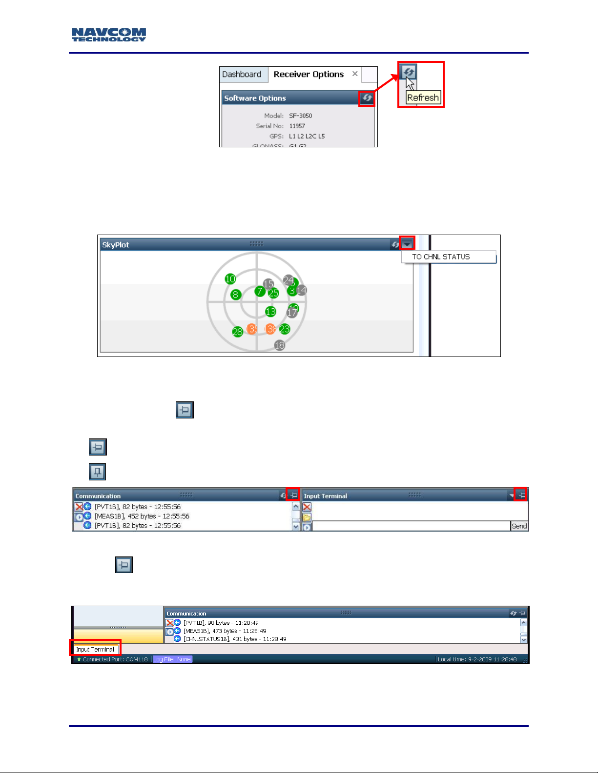
StarUtil 3000 User Guide – Rev G
Figure 3: Refresh Button
Menu Button
The Menu button is a down arrow in the top right corner of a window. It displays a pop-up menu.
The option in the example in Figure 4 switches the view from the Sky Plot window to the
Channel Status tab.
Figure 4: Menu Button
Auto Hide Button on the Communication and Input Terminal Windows
The Auto Hide button
is only on the Communication and Input Terminal windows, in the top
right corner of each window (see Figure 5). It has two functions:
Hide window
Return windows to Default view
Figure 5: Auto Hide Button
1. Click to hide the window. The window closes and a tab with the name of the hidden
window, for example, Input Terminal, appears in the lower left corner of the GUI
(see Figure 6).
Figure 6: Input Terminal Window Hidden
1-27

StarUtil 3000 User Guide – Rev G
2. Roll over the tab in the lower left corner of the GUI to open the hidden window (see
Figure 7).
Figure 7: Cursor on Tab Opens Hidden Window
The Input Terminal button on the Shortcut Bar also opens the Input Terminal
window when it is hidden (see Figure 10).
3. Click in the top-right corner of the open window. The window returns to its default
location.
Menu Bar
Not all menu options are described below.
Help
Provides access to the StarUtil 3000 User Guide and the Sapphire Technical Reference Manual
(see Related Documents in the fore-matter). Clicking About StarUtil 3000 on the Help menu
(see Figure 8) opens the splash-screen that appears when the program opens. The splashscreen displays version information and useful links to NavCom support, user guides, software
releases, and tools (see Figure 9).
Figure 8: StarUtil Help Menu
Figure 9: About StarUtil 3000
1-28

Shortcut Bar
Figure 10: Shortcut Bar
View/Edit Profile
Provides access to the User Profile controls (see Figure 11)
Refer to Chapter 6 – User Profiles.
StarUtil 3000 User Guide – Rev G
Figure 11: Save/Load/Delete User Profile
Data Logging
Provides access to the Data Logging controls (see Figure 12)
1-29

StarUtil 3000 User Guide – Rev G
Figure 12: Configure Logging Options
Refer to Chapter 10 – Data Logging for details about Figure 12.
Connections
Provides access to port settings and connection to the SF-3040 and the SF-3050 via the PC
COM Port, USB, Bluetooth, or Ethernet, as applicable (see Figure 13)
Refer to Chapter 2 – Establish Communications.
1-30

StarUtil 3000 User Guide – Rev G
Figure 13: Port Configuration – COM Port
Preferences
Future versions of StarUtil 3000 will allow the user to set custom views or layouts of the GUIs.
Receiver Status Bar
The Receiver Status Bar is always visible near the top of the GUI to provide a quick view of the
current status of the receiver (see Figure 14).
Figure 14: Receiver Status Bar
Base/Rover Info
Provides the Correction Format and LAT, LON, and
HT of the Base or Rover; the box heading is Base
Info or Rover Info, depending on the receiver
configuration.
Figure 15: Rover Info
1-31

StarUtil 3000 User Guide – Rev G
Navigation
Provides a quick check of the Navigation mode and Correction Age, which can be useful in
troubleshooting.
Figure 16: Navigation
Satellites
Provides useful information on the number of satellites used to
calculate the position and velocity and the number of satellites
tracked, plus DOP information
Figure 17: Satellites
Time in UTC
Provides quick access to the time, which is a useful reference.
For example, if there is a problem with position, the user can
write down the time of the problem and then troubleshoot during
post-processing the data that was logged at that time.
Figure 18: Time in UTC
Detailed Views Menu
Provides access to detailed views of important functions (see Figure 19). Each menu item
opens a tab on the main window.
Refer to Chapter 9 – Display of Positioning Performance.
1-32
Figure 19: Detailed Views Menu

Post Processing Menu
Provides access to the Data Parsing and Simulation controls
Refer to Chapter 11 – Post Processing
StarUtil 3000 User Guide – Rev G
Figure 20: Post Processing Menu
Refer to Figure 21 for the controls:
Data Parsing
The Data Parsing dialog box is used to extract selected NavCom proprietary messages from a
binary log file to *.txt files. Individual ASCII messages may also be extracted to a *.txt file. These
text files can be imported to other programs, such as Excel spreadsheet software, for further
analysis or use.
Simulation
The Simulation tab provides a way to access a simulation of receiver operation via the playing
of a saved log file (*.DAT)
Almanac
The Almanac tab provides a way to access the almanac data set for every satellite in the GPS
system. Without an almanac, it takes about 13 minutes after satellite lock to obtain and display
complete azimuth and elevation information. With a current almanac uploaded into memory, it
takes only a matter of seconds for the receiver to select the correct constellation of satellites
search at power up and during normal operation.
RINEX File Processing
RINEX file processing allows the conversion from NavCom proprietary binary data format of
recorded raw measurement data to industry standard RINEX data format for use in 3rd party and
on-line post-processing programs. Chapter 11 details the process.
1-33

StarUtil 3000 User Guide – Rev G
Figure 21: Data Parsing and Simulation
Receiver Setup Menu
Provides access to StarFire QuickStart and Navigation Modes for the SF-3040 and SF-3050
and to Configure SF-3040 Radio and Monitor SF-3040 Batteries for the SF-3040
Figure 22: Receiver Setup Menu
1-34

StarUtil 3000 User Guide – Rev G
StarFire QuickStart
StarFire QuickStart is a feature that eliminates the convergence period for StarFire-enabled
receivers. Sub-decimeter positioning is possible in < 5 minutes.
Refer to Chapter 7 – StarFire QuickStart
Figure 23: StarFire QuickStart
Navigation Modes
Provides access to navigation mode settings
Click the Retrieve Settings From the
Receiver button to retrieve the currently set
navigation modes.
Click the ON or OFF radio buttons to set the
navigation modes, and then click Apply
Changes to the Receiver button.
Figure 24: Set Navigation Modes
Communication Window
The Communication window displays all scheduled messages (see Figure 25). The scrolling
scheduled messages indicate that a valid connection is established at the correct baud rate.
1-35

StarUtil 3000 User Guide – Rev G
Figure 25: Communication Window – Valid Connection
A blue arrow indicates messages received by the GUI. A green arrow indicates
messages sent by the GUI.
COM Port Connection: Scrolling lines designated as “DATA” indicate a connection
is established, but the receiver’s baud rate is not correct (see
Figure 26).
Clicking the red “X” stops the scrolling.
The Communication window (and all other windows on the main GUI) can be
expanded by dragging the top edge of the window).
Figure 26: Communication Window – Connection at Incorrect Baud Rate
Input Terminal
Provides for the input of NavCom proprietary commands and queries; Figure 27 shows the
[version] command in the input field.
Refer to the Sapphire Technical Reference Manual for detailed information on
NavCom proprietary messages (see Related Documents in the fore-matter).
With a user profile loaded and in use, the receiver configuration may be
changed with individual commands via the Input Terminal. Commands
1-36

StarUtil 3000 User Guide – Rev G
entered via the Input Terminal are not saved to NVRAM through a receiver
power cycle. To maintain the new settings entered through the Input
Terminal, the current settings must be retrieved and saved as a new user
profile, or overwrite an existing profile before cycling receiver power.
Refer to Chapter 6 User Profiles/
Retrieve Current Receiver Settings and Save in Local File, and be sure to select
the check box labeled Check to save current receiver settings.
Figure 27: Input Terminal
The Input Terminal provides confirmation of actions performed via the GUI, for
instance, the upload of the Software Options file. In the example shown in Figure
28: Input Terminal – Confirmation, the file upload is successful.
Figure 28: Input Terminal – Confirmation
The command [USEPROFILE] “NONE” resets all of the user-controlled
configuration parameters to the factory default values. The receiver’s profile
remains set to NONE until another profile is successfully input. Refer to
Chapter 6 for information about user profiles.
The profile NONE is subject to change.
1-37

StarUtil 3000 User Guide – Rev G
This page is left blank intentionally
.
1-38

StarUtil 3000 User Guide – Rev G
Connections Button
Chapter 2 ........................................................... Establish Communications
This chapter provides instructions on how to
Establish communications between a PC running StarUtil 3000 and one of the following:
The SF-3040 via USB-COM1 or COM2 (the SF-3040 supports RS-232 and Bluetooth
communications connections, but not Ethernet)
The SF-3050 via COM1- LAN or COM2- USB (the SF-3050 supports RS-232/RS-422,
USB 2.0, Ethernet, and Bluetooth communications connections).
Configure and establish Bluetooth communications
Configure and establish basic Ethernet communications (for the SF-3050 only)
Refer to the SF-3040 GNSS Product User Guide or to the SF-3050 GNSS Product User
Guide for a list and descriptions of the supplied and optional data cables.
Establish Serial or USB Device Communications
USB Communications: The USB driver (“navcomx1c45x3050.inf”) must be in the same folder as
StarUtil 3000 for the USB port to auto-recognize the SF-3040 or the SF-3050. Confirm that the
driver is in the StarUtil 3000 folder on the PC (see Figure 1).
In addition, ensure that these files are in the same folder:
Starutil-3k_v1_1_x.exe
96-312007-3001RevX_Sapphire TRM.pdf
96-310029-3001RevX_StarUtil 3000.pdf.
1. Click the Connections button to establish communications between the PC and the SF-3040
or the SF-3050 (see Figure 29). The Port Configuration dialog box opens (see Figure 30).
Figure 29: Connections Button
Ethernet Communications (SF-3050 only): Typically an RS-232 or USB connection is not
required prior to an Ethernet connection. This requirement exists only if any of the following
apply:
A previous Ethernet connection was not terminated properly via the
[ETHVCOM]ON,0.0.0.0,0 command. The [ETHVCOM]ON,0.0.0.0,0 command is
included in the default system setting.
2-39
To restore the SF-3050 to the normal “listen for connection” mode so that an
Ethernet connection can be established, first establish an RS-232 or USB
connection. Then input [ETHVCOM]ON,0.0.0.0,0 via the Input Terminal window or
the appropriate user profile. The receiver will accept an Ethernet connection, or any
of these connection types: RS-232, USB, or Bluetooth.

StarUtil 3000 User Guide – Rev G
COM Port Settings
USB Settings
The EVCOM port is disabled by a previous [ETHVCOM]OFF command.
The EVCOM port is configured for a specific connection with an
[ETHVCOM]ON,<IP>,<port> command.
For remote operation of the SF-3050, connection to either COM1 or COM2 is highly
recommended as a backup to the Ethernet interface. The COM1 or COM2 backup
connection can be made via a cell modem, MOXA to Ethernet, etc.
Refer to Figure 30 for the steps below:
Figure 30: Port Configuration
2. Set the appropriate options according to the Connection Type and connect:
COM Port:
COM Port: the appropriate PC COM Port
Baud Rate: 57600 (keep the default)
Parity: None (keep the default)
Click for StarUtil to sequence through the available baud rates and connect
to the selected port.
Or
USB Port:
COM Port: the appropriate virtual PC COM port (refer to Configure Virtual PC
COM Port below, to establish and verify this port).
Show All Com Ports: Shows any ports that are USB configured but are not accessed by
clicking the USB radio button.
2-40

StarUtil 3000 User Guide – Rev G
Ping All Com Ports: Finds all ports including those configured in non-Windows operating
systems (e.g. Linux).
Click to connect to the selected port.
3. Verify that the SF-3040 or the SF-3050 is connected to the PC. Scrolling messages in the
Communication window indicate that a valid connection is established at the required baud
rate (see Figure 31).
Figure 31: Communication Window – Valid Connection
A blue arrow indicates received messages. A green arrow indicates messages sent
through the GUI.
COM Port Connection: Scrolling lines designated as “DATA” indicate a connection is
established, but the receiver’s baud rate is not correct (see Figure 32). Open the Port
Configuration dialog box. Click to connect.
Figure 32: Communication Window – Connection at Incorrect Baud Rate
Configure Virtual PC COM Port
Install the USB Driver
1. Place the provided Flash Drive into a USB port on the PC.
2. Browse to the NavCom folder and copy it to the PC.
3. Connect the USB cable from the receiver to the PC.
4. On the Welcome to the Found New Hardware Wizard dialog box, select the option Install
from a list or specific location (Advanced); then click the Next button (refer to Figure 33).
2-41

StarUtil 3000 User Guide – Rev G
Figure 33: Found New Hardware Wizard/Install Software
5. On the Please choose your search and installation options dialog box, select Search for the
best driver in these locations, and then click Browse (see Figure 34).
Figure 34: Found New Hardware Wizard/Choose Your Search and Installation Options
6. Browse to the NavCom\Utilities\StarUtil 3000 folder on your PC, open the folder of the most
current version of StarUtil 3000, and click OK (see Figure 35).
2-42

StarUtil 3000 User Guide – Rev G
Figure 35: NavCom/Utilities/StarUtil 3000/StarUtil 3000 Application
7. On the installation warning message, click the Continue Anyway button (see Figure 36).
Figure 36: Software Installation Warning Message
8. Click Finish on the Completing the Found New Hardware Wizard message dialog box (see
Figure 37).
2-43

StarUtil 3000 User Guide – Rev G
Figure 37: Completing the Found New Hardware Wizard
Verify the Virtual PC Com Port
9. On the Windows Explorer window, right-click My Computer and click Properties on the drop-
down menu (see Figure 38).
Figure 38: My Computer/Properties
10. On the System Properties dialog box, open the Hardware tab and then click the Device
Manager button (see Figure 39).
2-44

StarUtil 3000 User Guide – Rev G
Figure 39: System Properties/Hardware Tab/Device Manager Button
11. On the Device Manager window (see Figure 40), check to confirm that the COM port has
been configured.
2-45

StarUtil 3000 User Guide – Rev G
Figure 40: Device Manager
The SF-3040 or the SF-3050 must be in “[USBMODE] Device” for this connection
to work. This is the factory default setting. Refer to the Sapphire Technical
Reference Manual for details (see Related Documents in the fore-matter).
2-46

StarUtil 3000 User Guide – Rev G
Configure and Establish Bluetooth Communications
This section provides instructions to determine the Bluetooth Virtual COM port on a PC and
connect to the SF-3040 or the SF-3050 via Bluetooth.
The receiver Bluetooth baud rate is fixed at 230400 baud. It will not connect at any
other speed. The data rate is 10 Hz maximum. Communications performance is
dependent on the user’s Bluetooth device.
Refer to the SF-3040 GNSS Product User Guide or the SF-3050 GNSS Product
User Guide for Bluetooth compatibility (see Related Documents in the fore-matter).
Refer to the Sapphire Technical Reference Manual (TRM) for details on the use
of the Input Terminal [BTSET] command. Also see the note: To use an input
terminal to determine the Bluetooth virtual COM port on a PC and connect to the
receiver via Bluetooth, refer to the BTSET command in the Sapphire Technical
Reference Manual and to the next section in this guide.
Configure Bluetooth via the Input Terminal, below.)
1. Write down the SF-3040 or the SF-3050 serial number from the label on the receiver.
2. Turn on the receiver.
3. Plug the Bluetooth dongle (if one is being used1) into the proper port on the PC.
1
Many laptops incorporate Bluetooth, but not all will work; a dongle is an option.
4. Right-click the Bluetooth icon on the Windows taskbar and select Explore My Bluetooth
Places from the pop-up menu to open the My Bluetooth Places dialog box (see Figure 41).
5. Double-click Search for devices in range on the My Bluetooth Places dialog box to display a
list of in-range Bluetooth devices (see Figure 42).
Figure 41: My Bluetooth Places\Search for devices in range
2-47

StarUtil 3000 User Guide – Rev G
Figure 42: My Bluetooth Places\Entire Bluetooth Neighborhood
The naming convention for the SF-3040 is SF3040SerialNumber and for the
SF-3050, it is SF-3050SerialNumber.
Example: SF-3050,10280,2
For the SF-3050: Product types are SF-3050, SF-3050G, SF-3050S, and SF-
3050M in StarUtil 3000 ver. 1.0.1.5 and earlier. Later software versions will simply
report SF-3050.
6. Double-click the desired SF-3040 or SF-3050 receiver in the Bluetooth list (see Figure 42). A
Bluetooth Serial Port icon for the selected receiver is displayed (see Figure 43).
2-48
Figure 43: Bluetooth Serial Port Icon for Selected Receiver

StarUtil 3000 User Guide – Rev G
7. Double-click the Bluetooth serial port icon. An icon with green arrows is displayed, indicating
a connection is established between the Bluetooth Virtual COM port on the PC and the
Bluetooth dongle (see Figure 44).
Figure 44: Bluetooth Virtual COM Port Connection Established
If the PC requests a Bluetooth passcode, click OK. (There is no passcode for the
SF-3040 or the SF-3050 Bluetooth device; use the [BTSET] command on the Input
Terminal window to create a passcode in the receiver over the serial port if the
computer requires a passcode. Also see To use an input terminal to determine the
Bluetooth virtual COM port on a PC and connect to the receiver via Bluetooth, refer
to the BTSET command in the Sapphire Technical Reference Manual and to the
next section in this guide.
Configure Bluetooth via the Input Terminal, below.)
Not all Bluetooth devices are compatible with the SF-3040 or the SF-3050. Refer to
NavCom’s Support/Troubleshooting Guides web page for additional information.
8. Double-click the Bluetooth Serial Port icon shown in Figure 44 to display the Bluetooth
Serial Port dialog box, which confirms the configured COM port (see Figure 45).
2-49

StarUtil 3000 User Guide – Rev G
Figure 45: Bluetooth Virtual COM Port Connection Confirmed
9. To verify the assigned COM port, right-click the Bluetooth serial port icon (refer to Figure 43)
and select Properties on the pop-up menu (the Bluetooth Properties dialog box opens).
The window displays the Bluetooth Virtual COM port assigned to the Bluetooth dongle (see
Figure 46). Notate the COM port number for use in step 14 below.
Figure 46: Bluetooth Properties
10. Click OK on the Bluetooth Properties dialog box.
11. Open StarUtil 3000 on the PC.
12. Click the Connections button on the Shortcut Bar. The Port Configuration dialog box opens
(see Figure 47).
The Bluetooth module can be in either of two modes:
Command Mode – in this mode, the module receives commands (e.g., SETPIN,
DELPIN). Immediately upon powerup, Bluetooth is in Command mode. It has no active
connection. It can receive commands from any other port via an onboard processor
(Atmel).
2-50

StarUtil 3000 User Guide – Rev G
Data Mode – Once another device has been connected to the receiver via Bluetooth, an
active connection has been established and Bluetooth is in data mode, meaning it
maintains an active connection and can receive/send data via the Bluetooth port. (An
example would be a user creating a serial port using Bluetooth management software on
his laptop and then using StarUtil 3000 to connect to the receiver via that serial port.) In
this mode, the module has an active data connection with a connected device; it does
not receive commands because commands would be interpreted as data that need to be
passed to the connected device.
The only way to return Bluetooth to command mode once it is in data mode is
to issue a [BTSET]DISCONNECT command, but keep in mind that issuing
this command drops any active connection.
When the Bluetooth module is in “data mode,” the keywords are
ON/OFF/DISCONNECT. The remaining keywords return NAK - “BT module in data
mode”.
Turning on Bluetooth is associated with a software reset of the Bluetooth firmware.
When Bluetooth is ON, another in-range Bluetooth electronic device should be able
to detect the existence of the system.
Figure 47: Port Configuration – Bluetooth Settings
Refer to Figure 47 for the steps below:
13. Select Bluetooth as the Connection Type.
14. Select the appropriate COM Port from the dropdown list (refer to Figure 45 above).
15. Click to connect to the SF-3040 or the SF-3050.
2-51

StarUtil 3000 User Guide – Rev G
Icon
Indicator
Status
Description
Bluetooth
Off
Bluetooth off
Blue Blinking
Bluetooth on, no
connection
Blue
Bluetooth
connected
16. Verify Bluetooth connectivity:
View the Bluetooth LED on the SF-3040 or SF-3050 indicator panel. Refer to Table 2,
below, for Bluetooth LED indications.
Table 2: Bluetooth Connectivity LED Indication
Type [PING] in the Input Terminal and click the Send button; if properly connected, the
response is [PING]BT (see Figure 48).
Figure 48: Input Terminal – PING Command and Response
To use an input terminal to determine the Bluetooth virtual COM port on a PC and
connect to the receiver via Bluetooth, refer to the BTSET command in the Sapphire
Technical Reference Manual and to the next section in this guide.
Configure Bluetooth via the Input Terminal
This section provides instructions on how to use an input terminal to determine the Bluetooth
Virtual COM port on a PC and connect to the SF-3040 or the SF-3050 via Bluetooth.
1. Type the [BTSET]ON command in the Input Terminal to turn on the Bluetooth connection.
2. Type any of the following commands:
[BTSET]ADDR to request the Bluetooth device address
[BETSET]PIN to request the system PIN code
[BTSET]SETPIN to set the PIN code (aka passcode) for authorized connections
[BTSET]DELPIN to delete the PIN code (encryption no longer available)
[BTSET] RESET to cause a software reset of the Bluetooth device; Bluetooth drops the
connection and reboots
[BTSET]OFF to cause Bluetooth to enter “deep sleep” power-saving mode; no text
message is output.
[BTSET]DISCONNECT to disconnect the Bluetooth device and make it available to pair
with another device
When the Bluetooth is OFF, its interface with the UART on the PIO board is
disabled and all commands sent to the Bluetooth module are not accepted by the
module (until it is turned on again). No text message is output. Turning off
Bluetooth puts the module into “deep sleep” power-saving mode, thus making the
2-52

StarUtil 3000 User Guide – Rev G
RF invisible, and another in-range Bluetooth electronic device cannot detect the
existence of the system.
For further details, refer to the [BTSET] command in the Sapphire Technical
Reference Manual.
Ethernet Communications (SF-3050)
The SF-3050 supports both UDP and TCP connections. This section provides only the basic
configuration for a direct Ethernet connection between the SF-3050 and a PC.
Ethernet cables are not supplied with the SF-3050. These Ethernet cables are available via a
NavCom authorized representative or by contacting NavCom Sales Department:
Positronic 9-Pin Male to Ethernet RJ45 Plug
(P/N 94-310265-3006LF). This cable is used in the basic configuration below.
Y-Cable, Positronic 9-Pin Male to Ethernet RJ45 Plug & DB9S (RS-232/1PPS) (P/N 94-
310272-3006LF)
Refer to the SF-3050 GNSS Product User Guide for a list and descriptions of the
supplied and optional data cables (see Related Documents in the fore-matter).
Configure and Establish Ethernet Communications
There are 4 Ethernet modes: UDP1, UDP2, TCP1, and TCP2.
Perform the following steps to configure the receiver for an Ethernet connection:
1. Log on to an available port, such as USB or a serial COM port.
2. On the StarUtil 3000 Detailed Views menu, click View Raw Data and the Data View window
opens (refer to Figure 146). This is where you can view all response data.
3. On the Input Terminal window, enter [ETHVCOM] with no parameters to view the current
settings. It might look like this if port ETH1 has been busy:
[ETHVCOM] ON, 204.54.86.67, 4116, UDP2, 4361, ETH1
[ETHVCOM] OFF, 0.0.0.0, 0, UDP1, 4362, ETH2
[ETHVCOM] OFF, 0.0.0.0, 0, TCP1, 4363, ETH3
[ETHVCOM] OFF, 0.0.0.0, 0, TCP1, 4364, ETH4
These values may have been assigned dynamically and therefore may not be
usable. To create working parameters, enter the Virtual COM port command:
[ETHVCOM] ON, 0.0.0.0,0 UDP2, 4361, ETH1, where:
ON – sets the virtual port ON
“0.0.0.0” – puts the virtual port into a mode to accept the next caller (you)
“0” – clears the internal port
“UDP2” – names the protocol, from UDP1, UDP2, TCP1
“4361” – names the port (note: 4361 is the NavCom default port # for ETH1)
“ETH1” – identifies which logical port this command configures from ETH1/2/3/4
2-53

StarUtil 3000 User Guide – Rev G
4. On the Input Terminal window, re-enter the [ETHVCOM] command with no parameters to
verify the EVCOM settings:
[ETHVCOM] ON, 0.0.0.0, 0, UDP2, 4361, ETH1
[ETHVCOM] OFF, 0.0.0.0, 0, UDP1, 4362, ETH2
[ETHVCOM] OFF, 0.0.0.0, 0, TCP1, 4363, ETH3
[ETHVCOM] OFF, 0.0.0.0, 0, TCP1, 4364, ETH4
To verify a simple direct connection on port ETH1, enter the [PING] command on
the Input Terminal. The response should be [PING]ETH1.
5. On the Input Terminal window, enter [ETHCONFIG] to view the current Ethernet Port IP
settings to use for the connections dialog:
[ETHCONFIG]AUTO,204.54.86.4,255.255.254.0,204.54.87.1,204.54.87.20,204.54.87.39,
where:
“204.54.86.4” is the SF-3050 IP address; make a note of this
“255.255.254.0” is the network address mask
“204.54.87.1” is the gateway address
“204.54.87.20”is the primary DNS server
“204.54.87.39” is the secondary DNS server
The [ETHCONFIG] command can also be entered with MANUAL. (MANUAL
means assign a fixed IP and AUTO means use DHCP.) You can use AUTO,
but keep in mind that if the receiver drops offline, it may be difficult to retrieve
the IP address. If you specify MANUAL, the IP address does not change if
the receiver drops offline for power cycle, for downline load of new firmware,
etc.
If the MANUAL IP address is used other than on a direct connection between
a PC and the SF-3050, the user should have enough knowledge of
networking to ensure that the selected IP address does not conflict with other
units connected to the same LAN and is a valid address for that network.
The logical ports ETH1-ETH4 are used when configuring output messages on the
Ethernet ports (e.g., [OUTPUT]PVT1B,ONTIME,1,ETH1).
To make a change to [ETHCONFIG] permanent, enter [PROFILE]SAVEAS
“PROFILENAME” and power cycle the receiver. This change will not take effect
until after the power cycle.
Example:
[ETHCONFIG]MANUAL,204.54.86.4,255.255.254.0,204.54.87.1,204.54.87.20,
204.54.87.39
Basic Ethernet Configuration: Direct Connection via Static IP Address
Setup
This setup uses the factory default IP address of the SF-3050:
2-54

StarUtil 3000 User Guide – Rev G
IP Address Network Mask Gateway
192.168.0.2,255.255.255.0,0.0.0.0
The PC IP address is set manually in Windows.
1. Connect the Positronic 9-Pin connector of the Ethernet cable (P/N 94-310265-3006LF) to
COM1 – LAN of the SF-3050. Connect the RJ45 plug end to the computer.
2. In Windows, right-click My Network Places and select Properties from the pop-up menu. The
Network Connections window opens.
3. Right-click Local Area Connection (or the equivalent) and click Properties from the
pop-up menu. The Local Area Connection dialog box opens.
4. Click Internet Protocol (TCP/IP). See Figure 49.
Figure 49: Local Area Connection
5. Click the Properties button. The Internet Protocol dialog box opens.
Refer to Figure 50 for the steps below:
6. Select Use the following IP address.
2-55

StarUtil 3000 User Guide – Rev G
Figure 50: Internet Protocol
7. Enter the IP address for the PC. In this case, enter 192.168.0.100.
The first part of the IP address, 192.168.0, is the same for the SF-3050 and the PC. The last
part of the IP address must be unique for every device. In this case, it is 100 for the PC.
8. Press the Tab button on the keyboard. The Subnet mask is automatically populated.
9. Click the OK button on this dialog box and also on the Local Area Connection dialog box.
10. Continue to the next section for connection instructions.
Connect SF-3050 to the PC
1. Open StarUtil 3000.
2. Click the Connections button to establish communications between the PC and the
SF-3050 (see Figure 29). The Port Configuration dialog box opens.
Refer to Figure 51 for the steps below:
3. Select Ethernet as the Connection Type.
Do not change the default Ethernet Settings: 192.168.1.2 is the factory default IP
address of the SF-3050. The default virtual COM port is 4361 (logical port ETH1) and
the protocol is UDP2.
2-56

StarUtil 3000 User Guide – Rev G
Figure 51: Ethernet Port Configuration
4. Click .
5. Verify that the SF-3050 is connected to the PC. Messages scrolling in the Communication
window indicate that the connection is established (see Figure 31).
If an Ethernet connection is not established, use StarUtil 3000 to verify the IP
address of the SF-3050. A serial connection must be used to determine the
receiver’s IP address.
2-57

StarUtil 3000 User Guide – Rev G
Configure the Radio Modem (SF-3040)
For detailed instructions on installing the radio modem, refer to the SF-3040 UHF
Radio Module Installation Guide tucked inside the radio modem kit and the
SF-3040 GNSS Receiver Product User Guide, Chapter 7. Also refer to Configure
the Radio Settings in Chapter 8 of this guide, Configure the Radio Settings (SF-
3040)
Refer to Figure 53 for the steps below:
1. On the Receiver Setup menu, click Configure SF-3040 Radio (refer to Figure 52).
Figure 52: Receiver Setup/Configure SF-3040 Radio
2. To turn on the radio, select the ON option.
3. To set a frequency other than the default frequency, type a frequency between 403.00000
and 473.000000 in the FREQUENCY in MHz (in 25KHz steps) text box.
4. To set the receiver sensitivity threshold power level other than the default power level, type
a power level between -118 and -80 in the RX Threshold in dBm text box. A larger value (i.e.
closer to -80) makes the receiver less sensitive, which means the base and rover need to be
closer together for the radio link to function properly.
5. To use a network ID other than the default ID, type a network ID between 0 and 4090 in the
NETWORK ID text box.
6. Select a Channel Width option: 12.5 kHz or 25 kHz.
7. Select a Protocol Option: Satel 3AS (0); Pacific Crest 4-FSK (1); Pacific Crest GMSK 92);
TRIMTALK GMSK (3.) Options (1) (2) and (3) are Trimble receiver protocols.
8. Click to send the configuration to the radio using the selected parameters.
The radio settings can also be configured via the Input Terminal. Refer to the
[RADIO] and [OUTPUT]RADIOSTAT commands in the Sapphire Technical
Reference Manual.
2-58

StarUtil 3000 User Guide – Rev G
If this system is used with external Satel radios, the Satel radios must have the
FEC (forward error correction) feature set to Off and ‘Addressing’ must match the
SF-3040 network address.
Figure 53: SF-3040 Radio Configuration and Status
Request Battery Status (SF-3040)
For detailed instructions on charging and installing the SF-3040 battery packs, refer
to the SF-3040 GNSS Receiver Product User Guide, Chapter 6.
Refer to Figure 54 for the steps below:
2-59

StarUtil 3000 User Guide – Rev G
1. On the Receiver Setup menu, click Monitor SF-3040 Batteries (refer to Figure 54).
Figure 54: Receiver Setup/Monitor SF-3040 Batteries
Figure 55: SF-3040 Battery Configuration And Status
2. To view the current battery configuration and status, click (in the
example GUI, Figure 55, the retrieved status indicates that the battery packs are not
installed).
The batteries can also be monitored via the StarUtil 3000 Input Terminal. Refer to
the [OUTPUT]BATSTAT command in the Sapphire Technical Reference Manual for
details.
2-60

StarUtil 3000 User Guide – Rev G
Chapter 3 ....................................................................................... Firmware
This chapter provides instructions on how to
Determine if the firmware installed in the receiver is the most current
Determine firmware versions
Upload a unified firmware file to the receiver
Upload a single firmware file to the receiver
Verify loaded firmware
Determine If Installed Firmware Is the Most Current
The most current firmware must be installed to ensure the proper operation of the receiver.
The use of the Firmware Info window on the Receiver Options tab is the easiest way to
determine if the installed firmware is the most current. An alternative method is to use the Input
Terminal window. Both methods are described below.
Determine Firmware Versions – Receiver Options Tab/Firmware Info Window
1. Click Receiver Options on the Detailed Views menu to open the Receiver Options tab (see
Figure 56).
Figure 56: Receiver Options
2. Click
data.
(refresh) on the Firmware Info window (see Figure 57) to view the current output
The firmware is identified by version number. For example, the NAV firmware
displayed in Figure 57 is version 02.00.03. Firmware ensembles are always
referenced to the Navigation Firmware Number.
3-61

StarUtil 3000 User Guide – Rev G
NAV Firmware Version
Refresh
Button
NAV Firmware
Figure 57: Firmware Window -- Example of Installed Firmware
3. Browse to the NavCom\Firmware folder on the PC (see Figure 58).
4. The Firmware folder is copied from the SF-3040 Product Configuration USB Flash Drive or
the SF-3050 Product Configuration USB Flash Drive. It contains the most current firmware
(see example files in Figure 58). The firmware file extension is *.s19.
Figure 58: Firmware Folder Contents
5. Compare the current NAV Firmware version in the Firmware folder with the installed version
displayed in the Firmware Info window (see Figure 59).
3-62

StarUtil 3000 User Guide – Rev G
Old NAV Firmware
Current NAV Firmware
In the example below, the NAV firmware in the Firmware folder is more current than
the installed firmware. As a result, the user must update the NAV firmware in the
receiver.
Figure 59: Comparing Current and Installed Firmware
6. If the NAV firmware installed in the receiver is not the most current version:
a. Check the versions of the other firmware.
b. Write down all the firmware that must be updated.
c. Go to the Upload Firmware section.
Alternative Method to Determine Firmware Versions
1. Locate the Input Terminal at the bottom right of StarUtil 3000 (see Figure 60).
Figure 60: Input Terminal
2. Enlarge the Input Terminal window by dragging the top edge of the window.
3. Type [VERSION] in the field at the bottom of the Input Terminal window (see Figure 61).
3-63

StarUtil 3000 User Guide – Rev G
NAV Installed Firmware
Old NAV Firmware
Current NAV Firmware
Figure 61: Version Command
4. Click the Send button. The receiver returns a list of the currently installed firmware.
The firmware is identified by version number. For example, the NAV firmware displayed in
Figure 62 is version 01.00.00.003.
Figure 62: Example of Installed Firmware
5. Browse to NavCom\Firmware on the PC (refer to Figure 1).
6. The Firmware folder contains the most current firmware. The firmware file extension is
*.s19.
7. Compare the current NAV Firmware version in the Firmware folder with the installed version
displayed in the Input Terminal window (see Figure 63).
In the example below, the NAV firmware in the Firmware folder is more current than
the installed firmware. As a result, the user must update the NAV firmware in the
receiver.
3-64
Figure 63: Comparing Current & Installed Firmware

StarUtil 3000 User Guide – Rev G
8. If the NAV firmware installed in the receiver is not the most current version:
a. Check the versions of the other firmware.
b. Write down all the firmware that must be updated.
c. Go to the Upload Firmware section, below.
Upload Firmware
PC Baud Rate Requirements for Firmware Upload via Serial Connection
The requirements below only apply to firmware uploaded via a Serial connection. They do not
apply to firmware uploaded via a USB 2.0 Device or Ethernet connection.
GNSS Firmware
SF-3040 and SF-3050 COM1: The maximum PC baud rate to upload the appropriate
Bootloader and the NAV firmware file via a Serial connection is 115200.
SF-3040 and SF-3050 COM2: The required PC baud rate to upload the appropriate Bootloader
and the NAV firmware file via a Serial connection is 115200.
PWRIO Firmware
SF-3040 and SF-3050 COM2: The maximum PC baud rate to upload the PWRIO Bootloader
and the PWRIO firmware file via a Serial connection is 115200.
If the firmware fails to load, set the StarUtil baud rate and upload rate to 57600.
Turn the receiver OFF. Begin the file load and then turn the receiver ON. The
receiver allows 500ms at startup to “capture” the port at 57600, regardless of the
setting in the active profile. Once StarUtil starts the upload, it pings the receiver
every 200ms. A successful capture begins the file upload sequence.
Never attempt to upload firmware over the Bluetooth port.
Firmware may be uploaded via Ethernet or USB. Remote equipment users are
strongly encouraged to also remotely connect one of the RS-232 ports as a
backup, preferably COM 1.
Typically, if any firmware needs to be updated, it is NAV and PIOAPP. (Bluetooth
software is hardcoded and is loaded only at the time of manufacture.)
The receiver must be navigating at the time of the firmware upload.
Always cycle power to the receiver after a firmware update or a change to
Low Power settings. Failure to do so may result in the unit being unable to
track StarFire.
3-65

StarUtil 3000 User Guide – Rev G
Upload a Unified Firmware File
1. Click Receiver Options on the Detailed Views menu to open the Receiver Options tab (see
Figure 64).
Figure 64: Receiver Options Tab
2. Select Unified File Loader on the File Upload window (see Figure 65).
Figure 65: File Upload – Unified File Loader Option
3. Click .
4. Browse to the NavCom\Firmware folder on the PC (see Figure 66).
Figure 66: Firmware Folder and Contents
3-66

StarUtil 3000 User Guide – Rev G
5. Select the appropriate unified (SP_UFL) file to upload and click (see Figure 65).
6. The files to be uploaded are displayed on the Ready to Downline Load File dialog box with
the corresponding check boxes selected (see Figure 67). Select and deselect files to upload
as appropriate.
Figure 67: Ready to Downline Load File
7. Click .
8. Once the firmware files are uploaded, the Finished with All Downline Loads dialog box is
displayed (see Figure 68).
9. Click .
10. Check the Firmware Info window (see Figure 57) to view the current versions of all uploaded
firmware.
11. If any file failed to load, go to
12. Upload a Single Firmware File, below.
3-67

StarUtil 3000 User Guide – Rev G
Figure 68: Finished with All Downline Loads
Upload a Single Firmware File (SF-3050)
1. Click Receiver Options on the Detailed Views menu to open the Receiver Options tab (see
Figure 64).
2. Select Receiver Firmware on the File Upload window (see Figure 69).
Figure 69: File Upload – Receiver Firmware
3. Click and the Load Receiver Firmware dialog box opens (see
Figure 70).
3-68

Figure 70: Load Receiver Firmware
4. Click .
5. Browse to NavCom\Firmware on the PC (see Figure 61).
StarUtil 3000 User Guide – Rev G
Figure 71: Firmware Folder Contents
6. Select the appropriate firmware file to upload.
Upload Boot files before uploading application files if both types require
updating.
Example Boot File: SP_ boot1_ver2,0,1.s19
The format of the NAV firmware file is SPv + version number.s19.
Example NAV File: SPv1,0,0,4.s19 (see Figure 72).
3-69

StarUtil 3000 User Guide – Rev G
Figure 72: Settings for GNSS Firmware
Set these options:
Baud Rate:
Serial Connection: Refer to the section above, PC Baud Rate Requirements for
Firmware Upload Via Serial Connection.
USB 2.0 Device or Ethernet Connection: No selection is necessary. The speed of the
connection is automatically set.
Target:
Select SOLARIS to upload GNSS [firmware (see Figure 72).
Or
Select SOLARIS PIO to upload PWRIO firmware (see Figure 73).
Buffer Size: Do not set this option. The program automatically sets it.
Bootloader: Do not set this option. The program automatically sets it.
Force Load Firmware Without PING: Keep the default (unchecked).
Figure 73: Settings for PWRIO Firmware
7. Click . A Progress dialog box opens. At the end of the upload, a “Finished
loading” message indicating the number of bytes downloaded is displayed on the Progress
dialog box (see Figure 74). Click to continue.
3-70

8. Repeat the steps above to upload more firmware files.
Figure 74: Progress [Load Firmware] Dialog Box
StarUtil 3000 User Guide – Rev G
Always cycle power to the receiver after a firmware update or a change to
Low Power settings. Failure to do so may result in the unit being unable to
track StarFire.
3-71

StarUtil 3000 User Guide – Rev G
This page left blank intentionally
3-72

StarUtil 3000 User Guide – Rev G
No Geoid Model Is Loaded
GGM02 Is Loaded
GEOID99 Is Loaded
Chapter 4 ....................................................................... Geoidal Databases
This chapter provides instructions on how to
Determine whether or not a geoidal database, GGM02, or a user-defined Geoid Height Map
is loaded in the receiver
Upload the GGM02 database or a user-defined Geoid Height Map (identified as GEOID99 in
StarUtil 3000)
Check or Set Datum
In addition, this chapter provides the GEOIDAL99 format and file requirements.
User-defined Geoid Height Maps are based on the GEOIDAL99 format.
Refer to the Sapphire Technical Reference Manual for detailed information on the
commands used in this chapter: [GEOIDALMODEL], [GGM02STATUS], and
[DATUM] (see Related Documents in the fore-matter). Also see the Datum section
in this chapter.
Determine If a Geoid Model Is Loaded
Refer to Figure 75 for the steps below:
The GEOID status displayed in the PVT window has 3 possible values:
View the PVT window on either the Dashboard or the PVT tab to determine if the GGM02 or a
GEOID99 database is loaded in the receiver. Click (refresh) to ensure that the most current
data is displayed in the window.
If No Geoid Model is displayed, go to these sections to upload a geoidal database if desired:
If No Geoid Model is displayed, the Height and Altitude in the PVT window are the
4-73
Figure 75: PVT – GEOID
No Geoid Model, GGM02, or GEOID99 (user-defined geoidal database). Refer to the
section below, Geoid Height Map, for information on the GEOIDAL99 format.
Upload the GGM02 Database
Upload a User-Defined Geoid Height Map
same. If the GGM02 or GEOID99 database is loaded, the Height and Altitude
typically differ.

StarUtil 3000 User Guide – Rev G
The Input Terminal window can also be used to determine which geoidal model, if
any, is loaded in the receiver. Input [GEOIDALMODEL] to query the currently
selected geoidal database. In addition, the [GGM02STATUS] command may be
input to query the GGM02 database status in the receiver (see Figure 76).
Figure 76: Input Terminal – [GGM02STATUS] Command and Response
Upload the GGM02 Database
GGM02 stands for GRACE Gravity Model 02. It is derived from data recorded by
the Gravity Recovery and Climate Experiment (GRACE). This model is used to
compute geoidal separation, the difference between the WGS-84 earth ellipsoid
and mean-sea-level (geoid).
1. Click Receiver Options on the Detailed Views menu to open the Receiver Options tab (see
Figure 77).
Figure 77: Receiver Options
2. Select Load GGM02 in the File Upload window (see Figure 78).
Figure 78: File Upload – Load GGM02
3. Click . The Load GRACE Gravity Model 02 dialog box opens (see
Figure 79).
4-74

StarUtil 3000 User Guide – Rev G
Figure 79: Load Grace Gravity Model 02
4. Ensure that Restart receiver after loading (default) is checked so that the receiver will
perform a warm start (resets the receiver) after the upload is successful. (The user receives
no indication of the warm start. It is a background process.)
5. Click . An upload progress window opens. At the end of upload, a confirmation
box opens. Click OK.
6. Type [GEOIDALMODEL]GGM02 in the Input Terminal and click the Send button (see
Figure 80).
Figure 80: [GEOIDALMODEL]GGM02 Command and Response
7. View the PVT window on either the Dashboard or the PVT tab to confirm the successful
upload. GGM02 is identified as the current GEOID (see Figure 75).
GGM02 is not maintained as the Geoid Model through a receiver power cycle
in version 1.0.0.4 navigation firmware. This is corrected in later versions of
the firmware. To reset GGM02 as the Geoid Model, reload the appropriate
user profile or input [GEOIDALMODEL]GGM02 via the Input Terminal.
Geoid Height Map
This section provides
The GEOIDAL99 format and file requirements. The Geoid Height Map is based on the
GEOIDAL99 format.
Instructions for uploading a user-defined Geoid Height Map into the receiver
The Geoid Height Map is used to obtain more precision in a small area than the
GGM02 database can provide.
The user may create the Geoid Height Map, or download a Geoid Height Map from
the NOAA web site (URL below). The total number of points in the map must be <
262,000 (number of rows of latitude x number of columns of longitude).
If the total number of points is 262,000, the file upload is denied (see
Figure 83). The user is responsible for extracting the appropriate portion of the
original data set. A software extraction tool, XNTG.EXE, is also available from
the NOAA web site:
http://www.ngs.noaa.gov/GEOID/GEOID99/dnldgeo99pc1.html
4-75

StarUtil 3000 User Guide – Rev G
Data Item
Data Type
Units
Bytes
Header
SLAT – Southernmost latitude
R64
Degrees
8
WLON – Westernmost longitude
R64
Degrees
8
DLAT – Distance interval in latitude
R64
Degrees
8
DLON – Distance interval in longitude
R64
Degrees
8
NLAT – Number of rows of latitude
U32 4
NLON – Number of columns of longitude
U32 4
IKIND – Data type
The value always should be 1 (=> real *4)
U32 4
1 2 3 4 NLON
1
a
R1C1
a
R1C2
a
R1C3
a
R1C4
…
a
R1CNLON
2
a
R2C1
a
R2C2
a
R2C3
a
R2C4
…
a
R2CNLON
3
a
R3C1
a
R3C2
a
R3C3
a
R3C4
…
a
R3CNLON
4
a
R4C1
a
R4C2
a
R4C3
a
R4C4
…
a
R4CNLON
… … … … …
NLAT
a
RNLATC1
a
RNLATC2
a
RNLATC3
a
RNLATC4
a
RNLAT/CNLON
GEOIDAL99 Format
The GEOIDAL99 database file must be a binary file. It has a header plus a data section,
described below.
Table 3: GEOIDAL99 Header Format
The data section of the GEOIDAL99 database file follows immediately after the header. Table 4
displays the format, in which “a” represents a R32 Data Type, R = Row and C = Column. For
example, “a
” = 4 bytes (real number) of data at Latitude Row 3, Longitude Column 2.
R3C2
The data is variable length. NLAT is the total number of rows. NLON is the total number of
columns. (Table 3 defines NLAT and NLON.)
Table 4: GEOIDAL99 Data Format (variable length)
The data section is stored in the file beginning with the Westernmost (WLON)/Southernmost
(SLAT) point. In Table 4, this is the first point in Row 1: “a
“a
R1C1
”, “a
R1C2
”, “a
R1C3
”, “a
”, etc. Then Row 2 is stored: “a
R1C4
”. Row 1 (row-major) is stored:
R1C1
R2C1
”, “a
R2C2
”, “a
R2C3
”, “a
R2C4
”, etc.
This is continued sequentially for each row until the Easternmost/Northernmost point,
“a
RNLAT/CNLON
”, is stored. Each row creates a list of 4-byte real values NLON long, with DLON
longitudinal intervals along the row of latitude.
4-76

StarUtil 3000 User Guide – Rev G
Total Points < 262,000 Limit – Upload Permitted
Total Points 262,000 Limit – Upload Denied
Upload a User-Defined Geoid Height Map
1. Open the Receiver Options tab (see Figure 77).
2. Select Geoid Height Map on the File Upload window (see Figure 81).
Figure 81: File Upload– Geoid Height Map
3. Click . The Upload User-Defined Height Map dialog box opens (see Figure 82).
4. Click .
Figure 82: Upload User-Defined Height Map
Figure 83: Upload User-Defined Height Map – File Selected for Upload
4-77

StarUtil 3000 User Guide – Rev G
Refer to Figure 83 for the steps below:
5. Browse to and select the appropriate file. The path to the file appears in the upload field.
Data retreived from the file is displayed:
Southmost Latitude / Spacing (distance interval in latitude) / Rows (number of rows of
latitude)
Westmost Longitude / Spacing (distance interval in longitude) / Rows (number of
columns of longitude)
Total Points: < 262,000 limit. If the limit is exceeded, upload is denied.
6. Ensure that Restart receiver after loading (default) is checked so that the receiver will reset
(perform a warm start) after the upload is successful. (The user receives no indication of the
warm start. It is a background process.)
7. Click the Start Loading button. An upload progress window opens. At the end of upload, a
confirmation box opens. Click OK.
Ensure that the receiver has restarted from the warm start before performing the
next step. Monitor the PVT tab/Navigation Status window for a change from “Nav
invalid” to “Nav valid,” or monitor the LEDs on the front indicator panel of the
receiver. Refer to the SF-3040 GNSS Product User Guide or the SF-3050 GNSS
Product User Guide for details on LED indications (see Related Documents in the
fore-matter).
8. Type [GEOIDALMODEL]GEOIDAL99 in the Input Terminal window and click the Send
button (see Figure 84).
Figure 84: [GEOIDALMODEL] GEOIDAL99 Command and Response
9. View the PVT window on either the Dashboard or the PVT tab to confirm the successful
upload. GEOID99 is identified as the current GEOID (see Figure 75).
The Geoid Height Map (GEOID99) is not maintained as the Geoid Model through a
receiver power cycle in version 1.0.0.4 navigation firmware. This is corrected in
later versions of firmware. To reset the Geoid Height Map as the Geoid Model,
reload the appropriate user profile or input [GEOIDALMODEL]GEOIDAL99 via the
Input Terminal.
Datum
The datum can be provided by the system (built-in datum) or it can be defined by a user, in
which case the user supplies all parameters in the specific format from the command line (see
User-Defined Datum, below).
4-78

StarUtil 3000 User Guide – Rev G
Command:
[DATUM] [DATUM_SELECTION] DEFAULT, GDA94, USERDATUM
Parameter
Definition
DEFAULT
Default datum of the system (ITRF2008 or WGS84_G1150); no [PARAMETER_LIST] fields
WGS84
Transform StarFire ITRF2008 datum to WGS84 G1150.
No [PARAMETER_LIST] fields required.
GDA94
Geocentric datum of Australia (1994); no [PARAMETER_LIST] fields
USERDATUM
User-defined datum – the user provides the parameters in predefined format, [PARAMETER1],
…,[PARAMETER17] See Note 1, below.
Check Datum
The [DATUM] command allows a user to check the current datum (a reference surface to be
used in defining the 3D coordinates of a position).
Reference Frame at Default State
At default (when a user does not specify any particular reference frame), the output of the
navigation position (i.e., in the PVT1B message) will be the data in the default frame.
In this state, there will be no datum transformation to the position data. The navigation library
currently provides the solution in one of two reference frames (data): WGS84 or ITRF2008.
WGS84 is used for all positioning modes except StarFire.
The [DATUM] command returns the current datum mode and the values of the basic datum
parameter.
Command Format and Usage
Table 5: Datum Command Keywords
The StarFire network ground reference frame transitioned from the ITRF-2005 to
the ITRF-2008 system on January 21, 2014 at 0900 hours UTC. The back-up
systems provides fully redundant transition as of January 27, 2014 at 00:00 hours
UTC. For information on this transition, please consult the Troubleshooting Guide
StarFire GPS Transition to ITRF2008 Ground Reference Network located on the
Navcom website.
User-Defined Datum
The [DATUM] command is also used to set a specific datum for the output of the navigation
system to be reported upon (WGS84 or ITRF2008).
Reference Frame at Non-Default State
When a user selects a non-default datum, an additional transformation process takes place at
the navigation library level to transform the solution data into the user-specified target datum.
The table below lists the transformation(s) undertaken to transform the default datum to a userspecified datum:
4-79

StarUtil 3000 User Guide – Rev G
Datum at the Default State
Transformation
Solution in Datum
WGS84 (G1150)
WGS84 to User-Specified
User-Specified
ITRF2008 (after 21 Jan, 2014)
1. ITRF2008 to WGS84
2. WGS84 to User-Specified
Table 6: Predefined Datum Operating Modes
Special Considerations for the RTCM and RTK-Based Solutions
These are situations in the base and rover receiver setups in which the rover outputs the
position relative to the base position. The reference frame used in solutions from the rover is
reconciled with the data it receives from the base. That is, the base receiver dictates the
solution type it outputs as well as the solution type in the rover receivers that receive the
correction from the base.
Selecting a non-default datum on the rover can affect the accuracy of the output
position. If the user inputs a user datum at the base, the rover should not apply a
local datum transformation as this will cause the rover to have applied the datum
shift twice (once at the base and once at the rover). In this scenario, the rover is
positioning on the base’s locally corrected datum. If the base’s position is not
transformed to the local datum, then the rover must apply a datum transform to
achieve a local position. The best practice is to position the rover on a known
monument and validate the position accuracy of the receiver prior to positioning field
work. If the position is in error, validate that the transform settings are correct.
The command [DATUM]USERDATUM, [PARAMETER1], …,[PARAMETER17] sets the datum
to a user-defined datum. The user supplies the datum specifications as well as the
transformation model in the form of a list of parameters.
The parameters contain the following types of information and determine the type of
transformation model to be used:
1. Ellipsoid model
2. 3-parameter mode
3. 7-parameter mode
4. 14-parameter mode
The user must provide the following data block:
Ellipsoid model
Transformation models
3 parameters (required minimum list for user-defined datum)
7 parameters (optional extended parameter list– in addition to the 3-parameter model)
14 parameters (optional extended parameter list– in addition to the 7-parameter model)
In the below examples, the datum specifications from GDA94 (with simplification of the data
precision length) are used to demonstrate the user-input syntax for datum transformation.
Example 1: User-Defined Ellipsoid Model
4-80

StarUtil 3000 User Guide – Rev G
Definition
User-Defined Values
Semi-major Axis (a)
6378137.0e0
Inverse-flat (a/(a-b)
298.2572221010
Source Datum Reference Year
2000
Value Order #
Parameter
User-Defined Values
1
translation in x (in meters)
-0.0761
2
translation in y (in meters)
-0.01
3
translation in z (in meters)
0.04
Value Order #
Parameter
User-Defined Values
1 – 3
3-parameter model
3-parameter model translation values
4
rotation in x (in arc-sec)
0.008
5
rotation in y (in arc-sec)
0.009
6
rotation in z (in arc-sec)
0.009
7
Translation Scale (in ppm)
7.935e-03
Value Order #
Parameter
User-Defined Values
1 – 8
7-parameter model
7-parameter model translation values
9
translation rate in x (in
meter/year)
1.1e-02
10
translation rate in y (in
meter/year)
-4.5e-03
11
translation rate in z (in
meter/year)
-1.74e-02
12
rotation rate in x (in arc-sec /
year)
1.034e-3
13
rotation rate in y (in arc-sec /
year)
0.671e-03
14
rotation rate in z (in arc-sec /
year)
1.039e-03
15
Rotate rate scale (in ppm /
year)
-0.538e-03
Table 7: User-Defined Ellipsoid Model (with Sample Values)
The ellipsoid model parameters are mandatory in any transformation model.
Example 2: User-Defined Transformation Model (3-parameter model)
Table 8: 3-Parameter Model Transformation (with Sample Values)
Example 3: User-Defined Transformation Model (7-parameter model)
Table 9: 7-Parameter Model Transformation (with Sample Values)
Example 4: User-Defined Transformation Model (14-parameter model)
Table 10: 14-Parameter Model Transformation (with Sample Values)
4-81

StarUtil 3000 User Guide – Rev G
In examples 3 and 4, above, the user-defined value must be written in scientific
notation. A number in scientific notation is written as the product of a number
(integer or decimal) and a power of 10. The number has one digit to the left of the
decimal point. The power of ten indicates how many places the decimal point was
moved (e.g., the scientific notation equivalent of 0.011 is 1.1.e
1.25e-1).
-02,
and for 0.125, it is
4-82

StarUtil 3000 User Guide – Rev G
This page is intentionally left blank
4-83

StarUtil 3000 User Guide – Rev G
Chapter 5 .......................................................................... Software Options
This chapter provides instructions for uploading Software Options to enable the robust
functionality of the SF-3040 or the SF-3050 in the initial configuration purchased by the user, or
as a performance upgrade.
The SF-3040 and the SF-3050 are designed with a long-term performance upgrade path to
meet changing needs via software upgrades. Increased functionality does not typically require
the costly purchase of additional hardware.
The SF-3040 and SF-3050 software-enabled features (bundled for the SF-3050
and available for purchase individually for both the SF-3040 and the SF-3050),
cover a wide variety of applications. For the SF-3050, refer to the SF-3050 GNSS
Product User Guide for descriptions of the software options in each bundle: SF3050G, SF-3050S, and SF-3050M.
For the initial setup of the SF-3040 and the SF-3050, Software Options must be
loaded before loading the StarFire License (if purchased).
How to Purchase Software Options
Contact a NavCom authorized representative or the NavCom Sales Department
(sales@navcomtech.com) to purchase software options.
The options code is receiver-dependent and cannot be uploaded into multiple
receivers. Archive the software options file in case a reload is necessary.
Upload Software Options
The receiver must be navigating at the time of the software upload.
Perform these steps to load software options:
1. Click Receiver Options on the Detailed Views menu (see Figure 64) to open the Receiver
Options tab.
2. Locate the File Upload window on the tab. Software Options is the default file upload.
(Select Software Options if it is not selected.) See Figure 85.
Figure 85: File Upload – Software Options
3. Click .
4. Browse to NavCom\Software Options on the PC (see Figure 1).
5-84

StarUtil 3000 User Guide – Rev G
5. The software options file extension is *.opt. Each file includes the specific SF-3040 or SF3050 serial number in the file name, for example “SN123452”.
6. Select the software options file. The path to the file appears in the upload field
(see Figure 85).
7. Click . At the end of the upload, a confirmation box opens. Click OK.
The Input Terminal window also displays the outcome of the upload. Figure 86
shows a successful upload:
Figure 86: Input Terminal – Successful Software Upload
8. Click (refresh) on the Software Options window (see Figure 87) to display the
uploaded software options.
Figure 87: Software Options Window
“StarFire: Enabled” indicates that the StarFire Software Option is loaded. It does
not indicate that a StarFire License is installed. Refer to
Chapter 7/StarFire License Data for descriptions of the windows that provide
confirmation of an installed StarFire License.
9. Do not close StarUtil 3000. Perform one of these steps:
If a StarFire license is purchased, go to the How to Upload a StarFire License via Data
Cable section.
If a StarFire license is not purchased, go to How to Purchase Software Options.
5-85

StarUtil 3000 User Guide – Rev G
1
The SF-3040 or the SF-3050 returns the entire list of loaded software options. However,
StarUtil 3000 does not display the entire list in the Software Options window. Perform
these steps to verify the software in the SF-3040 or SF-3050:
1. Type the command [INPUTSWOPTION] in the Input Terminal window.
2. Click Send.
3. Highlight and copy the entire output.
4. Open any text editor, i.e., Microsoft Notepad, and paste the output there.
5. Verify that all software options have been uploaded to the receiver.
If the above method fails to upload any of the purchased software options, refer to
the next section below, Use the Input Terminal to Upload Software Options.
Use the Input Terminal to Upload Software Options
Perform the following steps to upload software options using the Input Terminal:
1. Open the software option file in any text editing program (e.g., Notepad)
2. Locate the option code at the bottom of the file (e.g., 74C91E91 789FA173 8E70296A
3259B2E6).
3. Highlight and copy the option code.
4. In the Input Terminal window, enter the command followed by the option code:
[INPUTSWOPTION] 74C91E91 789FA173 8E70296A 3259B2E6
5. Click Send on the Input Terminal window. If the software options loaded successfully, the
Input Terminal window displays a confirmation message (see Figure 86).
6. To view all currently loaded software options, click (refresh) on the Software Options
window (see Figure 87).
RTK Extend
RTK Extend1 is a purchased software option for Navcom StarFire receivers, such as the
SF-3040 and the SF-3050. It enables continuous real-RTK/RTK level positioning accuracy
during radio communication outages by utilizing NavCom’s global StarFire corrections. This
option is only required on the rover receiver. If a base receiver may be used as a rover at a
future date, it should be optioned for RTK Extend as well.
Enable RTK Extend
To enable RTK Extend:
RTK Extend Software Option: A valid RTK Extend Software Option must be installed in
the rover (see Figure 87)
Set Navigation Modes dialog box: “StarFire RTG” must be set to ON (see Figure 105)
Not standard in software bundles
5-86

StarUtil 3000 User Guide – Rev G
Verify RTK Extend Is Active
To verify that RTK Extend is active during a radio communication outage:
1. Ensure that RTK Extend is enabled (see the section immediately above).
2. Allow the receiver to obtain an RTK fix and verify that the StarFire signals are under track
(refer to Chapter 7/StarFire Performance). This typically occurs about 4 minutes into
operation. Once both of these conditions are met, turn off or disconnect the RTK radio
modem.
For best performance, StarFire convergence is required. Convergence usually
requires 30 min of continuous tracking. However, for RTK Extend to achieve
maximum performance, the rover must be fully converged, which typically requires
one (1) hour of operation.
3. Determine if RTK Extend is active on the PVT tab/Navigation Status window. RTK Extend is
active if the rover’s Nav Mode is: RTK X:StarFire RTG.
RTK Extend is not active if the rover’s Nav Mode is: RTK X:Unknown.
The Position FOM follows the StarFire Dual:RTG: 3D: Dual freq navigation mode,
but the positioning accuracy will stay at RTK levels (approx. 1cm) during the RTK
Extend period. View the Position FOM on the PVT Tab/Error Estimates Window
(see Figure 138).
5-87


StarUtil 3000 User Guide – Rev G
Chapter 6 ................................................................................. User Profiles
This chapter provides guidance to load, create, view (verify the profile in use), edit, save, and
delete User Profiles.
The SF-3040 and SF-3050 utilize individual commands, input via the Input Terminal, or groups
of commands, known as User Profiles, to set the various port assignments/parameters,
navigation parameters, and output message lists.
With a user profile loaded and in-use, the receiver configuration may be
changed with individual commands via the Input Terminal. Commands
entered using this technique are not saved to NVRAM through a receiver
power cycle. To maintain the new settings made through the Input Terminal
window, the current settings must be retrieved and saved as a new user
profile, or overwrite an existing profile before cycling receiver power. Refer to
the section in this chapter Retrieve User Profile Data from Receiver , and be
sure to select the check box Check to save current receiver settings.
The SF-3040 and SF-3050 provide for storage of up to 20 user profiles. Profiles may also be
stored on a PC. Each user profile is stored with a name. The user profile extension is *.npt.
StarUtil 3000, or another controller solution, is used to upload a user profile by its name.
The SF-3040 or SF-3050 may be initially configured with the factory default user profile or a
profile customized for the user by an authorized dealer.
Predefined, commonly used profiles are included on the supplied SF-3040 and SF-3050
Product Configuration USB Flash Drives, or are available by email.
Refer to the Sapphire Technical Reference Manual for detailed information on the
[PROFILE] and [USEPROFILE] commands (see Related Documents in the
fore-matter).
To open the Save/Load/Delete User Profile dialog box, click near the
top of the window.
How User Profiles Work
A new profile sent to the receiver replaces the currently used profile, but it does not necessarily
replace all the current parameter settings. The new profile replaces only those parameter
settings that it specifies.
For example:
The default navigation elevation mask is 7.
The user changes the elevation mask to 12 in a profile named “Test”. The user subsequently
sends profile “RTK” to the receiver. It replaces “Test”, and changes navigation mode settings
and port assignments.
But profile “RTK” does not specify a setting for the navigation elevation mask. So, the elevation
mask remains at 12, as previously set by the “Test” profile.
6-89

StarUtil 3000 User Guide – Rev G
Profile NONE
The command [USEPROFILE] “NONE” resets all of the user-controlled configuration
parameters to the factory default values. The receiver’s profile remains set to NONE until
another profile is successfully input.
Refer to the section below Factory Default Output Messages.
The profile NONE is subject to change.
Creating a User Profile
This section provides guidance in the creation of a user profile.
The example user profile below configures a receiver to use the StarFire Subscription Service.
Port 1 is the control port. In the example user profile:
The settings directly related to StarFire are highlighted in yellow.
The commands related to navigation performance and [OUTPUT] depend upon specific
application requirements.
Although the receiver in this example is not a Base or Rover, the user profile includes RTK
settings. This is because it is useful to create profiles that can be easily adapted to other
application requirements. Refer to Chapter 8 RTK Setup for an example user profile
configured for RTK.
Refer to the Sapphire Technical Reference Manual for detailed information on the
commands and output streams in the example user profile below (see Related
Documents in the fore-matter).
Refer to Chapter 7 StarFire Operation for StarFire licensing and software
requirements.
[NAVELEVMASK]7.00
[STARFIREALTSAT]OFF
[TRACKINGMODE]L1,ON,L2,ON,L2C,ON,L5,OFF,WAASEGNOS,ON,STARFIRE,ON,G1,ON,G2,ON
[NAVMEASUSE]L1,ON,L2,ON,L2C,ON,L5,OFF,WAASEGNOS,OFF,GLONASS,ON
[GEOIDALMODEL]GGM02
[REFNAME]"NAVCOMREF1"
[OUTPUT]NONE,,,-1
[OUTPUT]??,ONCHANGE,,1
[OUTPUT]OK,ONCHANGE,,1
[OUTPUT]PANICA,ONCHANGE,,1
[OUTPUT]PVT1B,ONTIME,0.1,1
[OUTPUT]MEAS1B,ONTIME,0.1,1
[OUTPUT]EPHEM1B,ONCHANGE,,1
[OUTPUT]ALM1B,ONCHANGE,,1
[OUTPUT]ECHODGPSB,ONCHANGE,,1
[OUTPUT]WAASDATAB,ONCHANGE,,1
[OUTPUT]TXRXINFOA,ONCHANGE,,1
[OUTPUT]CHNLSTATUS1B,ONTIME,1,1
[OUTPUT]SFSTATUS1B,ONCHANGE,,1
[OUTPUT]RTKSTATUS1B,ONCHANGE,,1
[OUTPUT]RTKSTATUS2B,ONCHANGE,,1
[OUTPUT]PHASENAVSTATUS1B,ONCHANGE,,1
[OUTPUT]NAVCONFIG1B,ONCHANGE,,1
Continued on next page…
6-90

StarUtil 3000 User Guide – Rev G
Putting the Port baud
rate settings at the end
of all user profiles is
recommended. Refer to
the section below,
Avoiding User Profile
Loading Errors, for
details.
[OUTPUT]SFLICENSEB,ONCHANGE,,1
[OUTPUT]MSGCANCELHISTORYB,ONCHANGE,,1
[OUTPUT]MSGCANCELCODESB,ONCHANGE,,1
[OUTPUT]??,ONCHANGE,,2
[OUTPUT]OK,ONCHANGE,,2
[OUTPUT]PANICA,ONCHANGE,,2
[OUTPUT]??,ONCHANGE,,3
[OUTPUT]OK,ONCHANGE,,3
[OUTPUT]PANICA,ONCHANGE,,3
[OUTPUT]??,ONCHANGE,,BT
[OUTPUT]OK,ONCHANGE,,BT
[OUTPUT]PANICA,ONCHANGE,,BT
[OUTPUT]??,ONCHANGE,,4
[OUTPUT]OK,ONCHANGE,,4
[OUTPUT]PANICA,ONCHANGE,,4
[OUTPUT]??,ONCHANGE,,USB1
[OUTPUT]OK,ONCHANGE,,USB1
[OUTPUT]PANICA,ONCHANGE,,USB1
[OUTPUT]??,ONCHANGE,,USB2
[OUTPUT]OK,ONCHANGE,,USB2
[OUTPUT]PANICA,ONCHANGE,,USB2
[OUTPUT]??,ONCHANGE,,FH1
[OUTPUT]OK,ONCHANGE,,FH1
[OUTPUT]PANICA,ONCHANGE,,FH1
[OUTPUT]??,ONCHANGE,,FH2
[OUTPUT]OK,ONCHANGE,,FH2
[OUTPUT]PANICA,ONCHANGE,,FH2
[OUTPUT]??,ONCHANGE,,ETH1
[OUTPUT]OK,ONCHANGE,,ETH1
[OUTPUT]PANICA,ONCHANGE,,ETH1
[OUTPUT]??,ONCHANGE,,ETH2
[OUTPUT]OK,ONCHANGE,,ETH2
[OUTPUT]PANICA,ONCHANGE,,ETH2
[2DNAVMODE]AUTO,0.0000
[PDOPLIMIT]10.0
[RTKTIMEOUT]15.0
[RTKFLOATTIMEOUT]300
[RTKMODE]rover,NCT,1
[PRDGPSMODE]RTCM1,OFF
[PRDGPSMODE]WAASEGNOS,ON
[PRDGPSMODE]SFRTG,ON
[PRDGPSTIMEOUT]RTCM1,300
[PRDGPSTIMEOUT]WAASEGNOS,300
[PRDGPSTIMEOUT]SFRTG,1200
[REFSTNPOS]0,0,0.000000,0,0,0.000000,0.000000
[L1FALLBACK]OFF
[PORT]2,19200,8,1,NONE
[PORT]3,57600,8,1,NONE
[PORT]4,57600,8,1,NONE
[PORT]1,115200,8,1,NONE
To output [ALM1B] data, use an [OUTPUT] command to schedule the message
6-91
Figure 88: Example User Profile – StarFire Configuration (SF-3050)
“onchange”, “once”, or “ontime”. The command does not differentiate which satellite
type of almanac to output. If the message is scheduled “once”, all satellite types of
almanac will be output. If it is scheduled “onchange”, only what’s updated will be
output. If it is scheduled “ontime”, the minimum interval is 60 seconds.

StarUtil 3000 User Guide – Rev G
Typical Commands and Parameters in User Profiles
Refer to the Sapphire Technical Reference Manual for the complete set of
commands and output streams utilized by the SF-3050 receiver (see
Related Documents in the fore-matter).
See also Chapter 8 RTK Setup for guidance to set up typical Base and Rover RTK
configurations.
[NAVELEVMASK]
This command sets the lowest elevation, in degrees, at which a receiver uses a satellite in the
navigation solution, measured from the horizon to zenith, 0º to 90º.
[TRACKINGMODE]
This command is used to enable or disable the receiver’s tracking of various signals or
frequencies. When a GPS signal or frequency is enabled or disabled, it applies to all GPS
satellites broadcasting that signal.
Enabling a specific tracking mode is necessary to allow the receiver to acquire and
track the signal, but it is not sufficient. The receiver must also be licensed for that
tracking mode, and the signal must be available.
WAAS satellites
This command is typically used for engineering experiments or receiver
testing. It is not recommended for use in other applications.
Multiple signals can be enabled or disabled at the same time, by repeating the pair
of signal names and the on/off keyword.
L1 cannot be turned off.
L2C requires L2. If L2 is turned off, it will force L2C off. Trying to turn L2C on when L2 is
turned off will have no effect.
G2 requires G1. If G1 is turned off, it will force G2 off. Trying to turn G2 on when G1 is
turned off will have no effect.
L5 and G2 tracking are mutually exclusive due to hardware resource sharing. Turning on
G2 tracking automatically turns off L5 tracking, and vice versa. The command
“[TRACKINGMODE] ALL, ON” turns on all signal tracking except for L5. The command
“[TRACKINGMODE] ALL,OFF” turns off all signal tracking, including L5 and G2.
Do not try to turn on L5 and G2 tracking at the same time. If one command
tries to turn on L5 and G2 at the same time, the later pair in the command will
overwrite the earlier pair.
6-92
Issuing the command [TRACKINGMODE]WAASEGNOS disables the
satellite.

StarUtil 3000 User Guide – Rev G
[NAVMEASUSE]
This command is used to enable or disable the receiver’s use of various signals or frequencies
for navigation. When a GPS signal or frequency is enabled or disabled, it applies to all GPS
satellites broadcasting that signal.
Enabling a specific measurement is necessary to allow the receiver to use the
signal measurement, but it is not sufficient. The receiver must also be licensed for
that tracking mode, and the signal must be available.
WAAS satellites contain similar signaling characteristics to GPS. The current SF-
3050 software does not support using WAAS measurement data in the navigation
solution.
L1 measurement usage is critical to the operation of the receiver. The
disabling of the L1 measurement (L1,OFF) places the receiver in an
“undefined configuration,” which may produce unpredictable results.
[TRACKINGMODE] and [NAVMEASUSE]
With regard to both the [TRACKINGMODE] and [NAVMEASUSE] commands, tracking of newer
navigation satellite signals (L2C and L5) is subject to the following:
The availability of signals from newer satellites
The "health bit" set to "healthy"
The SF-3050 navigation software updated to a version compatible with the signals
The user must choose to track either L5 or G2.
[OUTPUT]NONE,,,-1
This command is listed at the beginning of the [OUTPUT] commands in a user profile (see
Figure 89). It deletes all the outputs currently stored in the receiver. Then the outputs in the new
user profile are loaded.
The use of [OUTPUT]NONE,,,-1 ensures that none of the Outputs in the old user profile remain
stored in the receiver. Refer to the section above, How User Profiles Work.
[NAVELEVMASK]7.00
[STARFIREALTSAT]OFF
[TRACKINGMODE]L1,ON,L2,ON,L2C,ON,L5,OFF,WAASEGNOS,ON,STARFIRE,ON,G1,ON,G2,ON
[NAVMEASUSE]L1,ON,L2,ON,L2C,ON,L5,OFF,WAASEGNOS,ON,GLONASS,ON
[GEOIDALMODEL]GGM02
[REFNAME]"NAVCOMREF1"
[OUTPUT]NONE,,,-1
[OUTPUT]??,ONCHANGE,,1
[OUTPUT]OK,ONCHANGE,,1
[OUTPUT]PANICA,ONCHANGE,,1
[OUTPUT]PVT1B,ONTIME,0.1,1
[OUTPUT]MEAS1B,ONTIME,0.1,1
[OUTPUT]EPHEM1B,ONCHANGE,,1
Figure 89: [OUTPUT]NONE,,,-1
ONCHANGE and ONTIME
[OUTPUT]EPHEM1B,ONCHANGE,,1
[OUTPUT]MEAS1B,ONTIME,0.1,1
Figure 90: ONCHANGE and ONTIME
These settings (see Figure 90) indicate the following:
On Change: The receiver outputs the specified message at the highest rate the system can
6-93

StarUtil 3000 User Guide – Rev G
Rate
SF-3050 Bundles
SF-3040
G S M
STD
LAND-
PAK
Position, Velocity, and Time
1, 5*Hz
Std
Std
Std
Std
Std
10Hz
Opt
Opt
Std
Opt
Opt
25*Hz
Opt
Opt
Std
N/A
N/A
50, 100Hz
Opt
Opt
Opt
N/A
N/A
Raw Data
1, 5*Hz
Std
Std
Std
Std
Std
10Hz
Opt
Opt
Std
Opt
Opt
25*Hz
Opt
Opt
Std
N/A
N/A
50, 100Hz
Opt
Opt
Opt
N/A
N/A
output. The rate must be purchased. For example, if the receiver has a purchased rate of
25 Hz, the messages set at On Change are output at 25 Hz. (This rate only applies to
MEAS1B and PVT1B.) Some messages, like satellite almanac, are output after an update is
received over the air.
On Time: The receiver outputs the specified message at a rate the purchased rate. For
example, if the receiver has a purchased rate of 25 Hz, a message may be set at a lower
output rate, such as 10 Hz, or 0.1 seconds.
Position and Raw Data Rates
[OUTPUT]PVT1B,ONTIME,0.1,1
[OUTPUT]MEAS1B,ONTIME,0.1,1
Figure 91: Example Position and Raw Data Rates
In Figure 91, the highlighted parameter, 0.1, is the period in seconds of output. The formula
to determine the rate is as follows:
1 period in seconds of output = frequency (rate)
using this formula: 1.0 = 1Hz, 0.2 = 5Hz, 0.1 = 10Hz, 0.04 = 25Hz, 0.02 = 50Hz,
0.01 = 100Hz
The rate must be purchased. The maximum PVT output rate is 100Hz. The maximum
MEAS1B raw data output rate is 100Hz. Table 11 outlines the standard and optional rates of
each SF-3050 software bundle and for the SF-3040 Standard and LAND-PAK. The rates
may also be purchased individually.
With a user profile loaded and in-use, the easiest way to change the PVT or
MEAS1B output rate is to use the Input Terminal window. Refer to
Chapter 1 Introduction/Input Terminal.
Table 11: Position & Raw Data Rates
*5Hz is the default PVT and Raw Data Rate for software bundles G and S; 25Hz is
the default PVT and Raw Data Rate for bundle M.
6-94

StarUtil 3000 User Guide – Rev G
The position rate setting sets the output of the NCT Binary message PVT1B and
the NMEA messages GGA, RMC, and VTG, provided that those messages are set
to ONCHANGE.
The NCT Binary message MEAS1B does not follow the position rate. To match a higher
position rate, the user must schedule the output of MEAS1B. The rate must be a
purchased position and raw data rate.
The [PROCESSRATE] command is used to query the rate at which the navigation
solution and measurement solutions are updated.
[PDOPLIMIT]
This command sets the maximum position dilution of precision (PDOP) allowed for a valid
navigation solution. For example, [PDOPLIMIT] 10 sets the PDOP limit to 10. If the satellites
available for navigation have a geometry that results in a PDOP value that exceeds this limit,
the receiver will report that a navigation solution is not available.
The default setting for [PDOPLIMIT] is 10. When the PDOP reaches higher values,
large errors can occur in the navigation solution. If the PDOP limit is set too low,
availability of the navigation solution may decrease. NavCom’s specifications are
valid for a PDOP of 4.0.
The quality of GNSS data is dependent on the geometry between the receiver and
satellites; this includes the number of satellites that can be "seen" by the receiver
and the angle between the receiver and satellites as a constellation seen by the
receiver.
A satellite near the horizon usually provides a lower quality signal because of greater
atmospheric interference and the increased likelihood of the signal reflecting from
surface features; this is known as "multipath" error. The effect of geometry on GNSS
quality is measured by PDOP (position dilution of precision). PDOP is the overall
measure of the precision obtainable with a given satellite geometry. For example, a
PDOP of 4 or less yields excellent precision, a PDOP between 5 and 7 is acceptable
and a PDOP of 7 or more is considered poor.
[GEOIDALMODEL]GGM02
This command selects the GGM02 geoidal database. In the initial release v1.0.0.4, GGM02 is
not maintained as the Geoid Model through a receiver power cycle. This is corrected in later
releases. Loading a user profile that includes this command is a quick way to reset GGM02 as
the Geoid Model. Refer to Chapter 4/Upload The GGM02 Database.
Only two types of Geoidal models may be loaded in the SF-3050: GGM02 and
GEOIDAL99. The GGM02 geoidal database is factory loaded. The user may define
a GEOIDAL99 database and load it into the receiver. The GEOIDAL99 model is
typically more precise than the GGM02 model. If loaded, it is typically preferred.
When the DEFAULT keyword is used, the receiver automatically selects the
Geoidal model according to this default priority list: GEOIDAL99, GGM02, NONE.
The model listed first, GEOIDAL99 is used if it is loaded in the receiver; otherwise,
the next model, GGM02, is used if it is loaded. If neither Geoidal model is loaded,
NONE is selected. The sequential order of the priority list cannot be changed by the
user. The GEOIDAL99 model is listed first because it typically provides the highest
precision.
6-95

StarUtil 3000 User Guide – Rev G
If the user does not desire the automatic selection of the loaded Geoidal model(s), based
on his geographic position, he can input a specific model. This supersedes the DEFAULT
keyword, which then must be input when automatic selection is desired.
[2DNAVMODE]
This command is used to enable or disable GNSS navigation with height-constrained (2D
navigation) and to set the height constraint when the receiver computes a 2D navigation
solution.
Use 2D navigation mode only when the height can be constrained accurately.
Otherwise, large errors may occur in the position solution.
Upper height limit imposed due to export limitations.
Examples: [2DNAVMODE]AUTO,0.0000
Commands the receiver to automatically transition between 3D (4 satellite
minimum) and 2D (3 satellite minimum) navigation. This can also be determined by
DOP values, even if 5 satellites are available. In 2D navigation, the last valid
computed height measurement is used.
[2DNAVMODE] ALWAYS, 10.5
Commands the receiver to switch to 2D (3 satellite minimum) navigation and set 2D
height to 10.5 meters. The receiver must compute an initial 3D navigation solution
before it transitions to 2D navigation. After 2D navigation is established, the receiver
will not transition back to 3D navigation.
View the PVT tab for the current nav mode and indication of 3D or 2D navigation.
[L1FALLBACK]
This command is typically set to OFF to disable the L1 fallback (or optimized shading) option.
When L1 fallback is ON, dGPS mode precedence is set to Dual 3D Single 3D Dual 2D
Single 2D.
Uploading User Profiles
Avoiding User Profile Loading Errors
StarUtil 3000 v.1.0.0 and later scans user profiles before loading them to adjust port settings
and reduce the likelihood of communication errors. Communication errors still occur, and this
section aids in resolving common issues.
As a user profile is loaded into the receiver, each command line is acted upon as it is received.
A profile loading error occurs if the communication link between the PC and the receiver is
broken before all command lines are received. To avoid this loading error, the best practice is to
preview the control port baud rate in a user profile before loading the profile.
For example, a PC is currently connected to the SF-3050 COM Port 1 at 57600 bps. So, Port 1
is the current control port. In the example in Figure 92, previewing the profile to be loaded
reveals that the receiver Port 1 baud rate (highlighted) will be changed to 115.2 kbps. If no
adjustments are made prior to loading this profile, all of the commands following the Port 1
6-96

StarUtil 3000 User Guide – Rev G
Lost Commands
statement will be lost as a result of the receiver changing baud rates and the PC remaining at
57600 bps (see Figure 93).
[OUTPUT]PANICA,ONCHANGE,,ETH2
[PORT]1,115200,8,1,NONE
[PORT]2,19200,8,1,NONE
[PORT]3,57600,8,1,NONE
[PORT]4,57600,8,1,NONE
[2DNAVMODE]AUTO,0.0000
[PDOPLIMIT]10.0
[RTKTIMEOUT]15.0
[RTKFLOATTIMEOUT]300
[RTKMODE]rover,NCT,1
[PRDGPSMODE]RTCM1,OFF
[PRDGPSMODE]WAASEGNOS,ON
[PRDGPSTIMEOUT]RTCM1,300
[PRDGPSTIMEOUT]WAASEGNOS,300
[REFSTNPOS]0,0,0.000000,0,0,0.000000,0.000000
[L1FALLBACK]OFF
Figure 92: Example User Profile – Control Port
[OUTPUT]PANICA,ONCHANGE,,ETH2
[PORT]1,115200,8,1,NONE
[PORT]2,19200,8,1,NONE
[PORT]3,57600,8,1,NONE
[PORT]4,57600,8,1,NONE
[2DNAVMODE]AUTO,0.0000
[PDOPLIMIT]10.0
[RTKTIMEOUT]15.0
[RTKFLOATTIMEOUT]300
[RTKMODE]rover,NCT,1
[PRDGPSMODE]RTCM1,OFF
[PRDGPSMODE]WAASEGNOS,ON
[PRDGPSTIMEOUT]RTCM1,300
[PRDGPSTIMEOUT]WAASEGNOS,300
[REFSTNPOS]0,0,0.000000,0,0,0.000000,0.000000
[L1FALLBACK]OFF
Figure 93: Example User Profile – Broken Communication Link Results in Lost Commands
Scrolling command mnemonics in the Communication window indicate a valid
connection. Scrolling lines designated as “DATA” indicate a broken communication
link (see Figure 94).
Figure 94: Indication of Broken Communication Link
Perform these steps to avoid the user profile loading error explained above:
Move the [PORT] commands to the end of the user profile. In addition, move the control port
command to the bottom-most position (see Figure 95).
6-97

StarUtil 3000 User Guide – Rev G
Control Port
[OUTPUT]PANICA,ONCHANGE,,ETH2
[2DNAVMODE]AUTO,0.0000
[PDOPLIMIT]10.0
[RTKTIMEOUT]15.0
[RTKFLOATTIMEOUT]300
[RTKMODE]rover,NCT,1
[PRDGPSMODE]RTCM1,OFF
[PRDGPSMODE]WAASEGNOS,ON
[PRDGPSTIMEOUT]RTCM1,300
[PRDGPSTIMEOUT]WAASEGNOS,300
[REFSTNPOS]0,0,0.000000,0,0,0.000000,0.000000
[L1FALLBACK]OFF
[PORT]2,19200,8,1,NONE
[PORT]3,57600,8,1,NONE
[PORT]4,57600,8,1,NONE
[PORT]1,115200,8,1,NONE
Figure 95: Example User Profile – [PORT] Commands at End of User Profile
Before uploading the user profile:
Input a new baud rate. From the user profile, copy the command string for the control
port, for example, [PORT]1,115200,8,1,NONE.
Paste the command string into the Input Terminal window in StarUtil 3000 (see the
example in Figure 96).
Figure 96: Input of New Baud Rate
Click the Send button.
Re-establish communication between the PC and the receiver at this new baud rate.
Upload the user profile.
Because the PC baud rate matches the receiver baud rate in the user profile, the
entire user profile loads without communication errors.
Before Uploading a User Profile
Before uploading a user profile, it is important to preview the user profile in a
text editor, such as Microsoft Notepad (see Edit User Profile).
Check the control port baud rate specified in the user profile. Refer to the section
Avoiding User Profile Loading Errors, above, for details.
Ensure that the user profile meets the requirements of the current application.
Verify Profile in Use
Refer to Figure 97 for the steps below:
1. Click on the shortcut bar at the top of StarUtil 3000.
6-98
 Loading...