

Page 1
Stt
S
arr
a
Uttiill--
U
3
3
0
0
0
0
0
0
UUsseerr GGuuiidde
e
NavCom Technology, Inc.
20780 Madrona Avenue
Torrance, California 90503 USA
Tel: +1 310.381.2000
Fax: +1 310.381.2001
sales@navcomtech.com
www.navcomtech.com
P/N: 96-310029-3001
Page 2

StarUtil-3000 User Guide – Rev A
This page is left blank intentionally
Page 3

StarUtil-3000 User Guide – Rev A
Table of Contents
List of Figures............................................................................................................................iv
List of Tables.............................................................................................................................vii
Notices......................................................................................................................................viii
Copyright............................................................................................................................................viii
Trademarks ........................................................................................................................................viii
User Notice.........................................................................................................................................viii
Limited Warranty ................................................................................................................................viii
StarFire™ Licensing.............................................................................................................................ix
USG FAR..............................................................................................................................................ix
Global Navigation Satellite System......................................................................................................ix
Revision History..........................................................................................................................x
Use of this Document................................................................................................................xi
Related Documents .................................................................................................................................xi
SF-3050 GNSS Products User Guide..................................................................................................xi
SF-3050 Quick Start Guide ..................................................................................................................xi
Sapphire Technical Reference Manual................................................................................................xi
RINEXUtil User Guide..........................................................................................................................xi
NavCom Release Notes.......................................................................................................................xi
Related Standards..................................................................................................................................xii
ICD-GPS-200 ......................................................................................................................................xii
Galileo OS SIS ICD.............................................................................................................................xii
GLONASS ICD, Version 5.0, 2002......................................................................................................xii
RTCM-SC-104.....................................................................................................................................xii
CMR, CMR+........................................................................................................................................xii
RINEX..................................................................................................................................................xii
QZSS...................................................................................................................................................xii
NMEA-0183.........................................................................................................................................xii
Publicly-Operated SBAS Signals ........................................................................................................xii
RTCA/DO-229D..............................................................................................................................xii
WAAS (Wide Area Augmentation System).....................................................................................xii
EGNOS (European Geostationary Navigation Overlay Service)...................................................xiii
MSAS (MTSAT Satellite-based Augmentation System)................................................................xiii
GAGAN (GPS Aided Geo Augmented Navigation) .......................................................................xiii
Chapter 1 Introduction .......................................................................................................15
StarUtil-3000 Overview..........................................................................................................................15
Features..............................................................................................................................................15
File Naming Conventions ...................................................................................................................15
Save Folder/Files to PC.........................................................................................................................16
StarUtil-3000 GUI...................................................................................................................................16
Window Features................................................................................................................................17
How Output Data Is Polled.............................................................................................................17
Refresh Button...............................................................................................................................17
Menu Button...................................................................................................................................17
Auto Hide Button – Communication and Input Terminal Windows................................................18
Menu Bar............................................................................................................................................18
Help................................................................................................................................................18
Short Cut Bar......................................................................................................................................19
View/Edit Profile.............................................................................................................................19
Datalogging....................................................................................................................................19
Connections...................................................................................................................................20
Preferences....................................................................................................................................20
Receiver Status Bar............................................................................................................................21
Base/Rover Info .............................................................................................................................21
Navigation......................................................................................................................................21
i
Page 4

StarUtil-3000 User Guide – Rev A
Satellites.........................................................................................................................................21
Time in UTC...................................................................................................................................21
Detailed Views Menu..........................................................................................................................22
Post Processing Menu........................................................................................................................23
Data Parsing ..................................................................................................................................23
Simulation ......................................................................................................................................23
Receiver Setup Menu.........................................................................................................................24
StarFire QuickStart.........................................................................................................................24
Navigation Modes ..........................................................................................................................24
Communication Window.....................................................................................................................25
Input Terminal.....................................................................................................................................26
Chapter 2 Establish Communications ..............................................................................27
How to Establish Serial or USB Device Communications.....................................................................27
How to Configure and Establish Bluetooth Communications................................................................ 29
How to Configure and Establish Ethernet Communications.................................................................. 32
Basic Ethernet Configuration: Direct Connection Via Static IP Address............................................33
Setup..............................................................................................................................................33
Connect SF-3050 to PC.................................................................................................................34
Chapter 3 Firmware ............................................................................................................37
Determine If Installed Firmware Is Most Current...................................................................................37
Determine Firmware Versions – Receiver Options Tab/Firmware Info Window................................37
Alternative Method to Determine Firmware Versions.........................................................................38
Upload Firmware....................................................................................................................................40
PC Baud Rate Requirements for Firmware Upload Via Serial Connection .......................................40
Upload Firmware................................................................................................................................40
Chapter 4 Geoidal Databases ............................................................................................43
Determine If Geoid Model Is Loaded.....................................................................................................43
Upload The GGM02 Database..............................................................................................................44
Geoid Height Map..................................................................................................................................45
GEOIDAL99 Format...........................................................................................................................46
Upload A User-Defined Geoid Height Map ........................................................................................47
Chapter 5 Software Options...............................................................................................49
How to Purchase Software Options.......................................................................................................49
Upload Software Options.......................................................................................................................49
RTK Extend............................................................................................................................................51
Enable RTK Extend............................................................................................................................51
Verify RTK Extend Is Active ...............................................................................................................51
Chapter 6 User Profiles ......................................................................................................53
How User Profiles Work.........................................................................................................................53
Profile NONE .........................................................................................................................................54
Creating A User Profile..........................................................................................................................54
Typical Commands And Parameters In User Profiles........................................................................56
[NAVELEVMASK] ..........................................................................................................................56
[TRACKINGMODE]........................................................................................................................56
[NAVMEASUSE]............................................................................................................................56
[TRACKINGMODE] And [NAVMEASUSE]....................................................................................57
[OUTPUT]NONE,,,-1......................................................................................................................57
ONCHANGE And ONTIME............................................................................................................57
Position And Raw Data Rates........................................................................................................58
[PDOPLIMIT]..................................................................................................................................59
[GEOIDALMODEL]GGM02............................................................................................................59
[2DNAVMODE] ..............................................................................................................................59
[L1FALLBACK]...............................................................................................................................60
Avoiding User Profile Loading Errors.....................................................................................................60
Before Uploading A User Profile............................................................................................................62
Upload User Profile................................................................................................................................62
Upload User Profile From Local File ..................................................................................................62
ii
Page 5

StarUtil-3000 User Guide – Rev A
Retrieve Stored User Profile From Receiver And Upload..................................................................63
Retrieve User Profile Or Current Settings And Save In Local File ........................................................64
Retrieve User Profile From Receiver And Save In Local File ............................................................64
Retrieve Current Receiver Settings And Save In Local File...............................................................65
Edit User Profile.....................................................................................................................................66
Delete User Profile(s) From Receiver....................................................................................................66
Verify Profile In Use...............................................................................................................................67
Factory Default Output Messages .........................................................................................................68
Factory Default NCT Messages .........................................................................................................68
Message Descriptions....................................................................................................................68
Chapter 7 StarFire Operation.............................................................................................71
Description of the StarFire Network.......................................................................................................71
RTK Extend............................................................................................................................................71
How to Access the StarFire Service......................................................................................................72
StarFire Licensing Terminology.............................................................................................................72
Point Radius.......................................................................................................................................73
StarFire Satellites...................................................................................................................................73
Before Uploading A StarFire License ....................................................................................................73
How To Upload StarFire License Via Data Cable ................................................................................. 74
Over The Air StarFire Licensing ............................................................................................................75
Over The Air Broadcast......................................................................................................................75
StarFire License Data............................................................................................................................76
StarFire Tab........................................................................................................................................76
Receiver Options Tab.........................................................................................................................77
StarFire Licenses Window .............................................................................................................77
Cancel License Status Window .....................................................................................................78
How To Cancel StarFire License...........................................................................................................78
StarFire Performance.............................................................................................................................78
Confirm StarFire Navigation...............................................................................................................78
StarFire Tab........................................................................................................................................79
StarFire Window.............................................................................................................................80
Satellite Locations Window............................................................................................................80
Define Satellite Window.................................................................................................................82
Failed Search .....................................................................................................................................82
StarFire QuickStart ................................................................................................................................83
Example of QuickStart Use ................................................................................................................83
QuickStart State .................................................................................................................................84
Chapter 8 RTK Setup..........................................................................................................85
Creating A RTK User Profile..................................................................................................................85
Example RTK User Profiles................................................................................................................ 85
Solution Control..................................................................................................................................88
[2DNAVMODE] ..............................................................................................................................88
[ANTENNAHIGHT].........................................................................................................................88
[L1FALLBACK]...............................................................................................................................88
[NAVELEVMASK] ..........................................................................................................................89
[NAVMEASUSE]............................................................................................................................89
[PDOPLIMIT]..................................................................................................................................89
[PRDGPSMODE]...........................................................................................................................89
[PRDGPSTIMEOUT]......................................................................................................................89
[SOLIDEARTHTIDE]......................................................................................................................90
RTK Base Control...............................................................................................................................90
[RTKMODE]...................................................................................................................................90
[REFNAME]....................................................................................................................................90
Set Up Base Position.....................................................................................................................90
[RTKSTNID]...................................................................................................................................91
[RTKSTATUS1B] ...........................................................................................................................91
[RTKTIMEOUT]..............................................................................................................................91
iii
Page 6

StarUtil-3000 User Guide – Rev A
[RTKFLOATTIMEOUT]..................................................................................................................91
[RTKMULTIPATH]..........................................................................................................................91
How to Set Navigation Modes ...............................................................................................................92
NCT Legacy Products............................................................................................................................92
Chapter 9 Display of Positioning Performance................................................................93
Dashboard ............................................................................................................................................. 93
PVT.....................................................................................................................................................93
Velocity & Headings ...........................................................................................................................94
Sky Plot...............................................................................................................................................94
StarFire...............................................................................................................................................94
Alerts...................................................................................................................................................94
PVT Tab.................................................................................................................................................95
PVT.....................................................................................................................................................95
Navigation Status ...............................................................................................................................95
Antenna Off-Set..................................................................................................................................96
Solid Earth Tide..................................................................................................................................97
Requirements for output of SET corrections..................................................................................97
Velocity...............................................................................................................................................98
Error Estimates...................................................................................................................................98
Solution Plot .......................................................................................................................................99
Menu Options.................................................................................................................................99
Channel Status Tab.............................................................................................................................101
Description of Data...........................................................................................................................102
MEAS1B Tab.......................................................................................................................................103
Description of Data...........................................................................................................................103
GPS/SBAS...................................................................................................................................103
GLONASS....................................................................................................................................104
Sky Plot Tab.........................................................................................................................................105
View Raw Data Tab.............................................................................................................................106
NMEA Tab ...........................................................................................................................................107
How to Schedule NMEA Messages .................................................................................................107
Chapter 10 Datalogging......................................................................................................109
Configure Logging Options..................................................................................................................109
Logging to USB Flash Drive Via USB Host Cable...............................................................................110
Setup ................................................................................................................................................111
Logging.............................................................................................................................................111
Chapter 11 Post Processing ..............................................................................................113
Data Parsing ........................................................................................................................................113
Simulation ............................................................................................................................................114
Chapter 12 1PPS/Events ....................................................................................................115
Configuration........................................................................................................................................116
A NCT Solid Earth Tide (SET) Message Format...............................................................117
List of Figures
Figure 1: NavCom Folder............................................................................................................16
Figure 2: StarUtil-3000 GUI ........................................................................................................16
Figure 3: Refresh Button.............................................................................................................17
Figure 4: Menu Button ................................................................................................................17
Figure 5: Auto Hide Button..........................................................................................................18
Figure 6: Input Terminal Window Hidden....................................................................................18
Figure 7: Cursor On Tab Opens Hidden Window.......................................................................18
Figure 8: About StarUtil 3000......................................................................................................18
Figure 9: Short Cut Bar...............................................................................................................19
Figure 10: Save/Load/Delete User Profile ..................................................................................19
iv
Page 7

StarUtil-3000 User Guide – Rev A
Figure 11: Configure Logging Options........................................................................................19
Figure 12: Port Configuration Window........................................................................................20
Figure 13: Receiver Status Bar...................................................................................................21
Figure 14: Rover Info..................................................................................................................21
Figure 15: Navigation..................................................................................................................21
Figure 16: Satellites....................................................................................................................21
Figure 17: Time in UTC...............................................................................................................21
Figure 18: Detailed Views Menu.................................................................................................22
Figure 19: Post Processing Menu...............................................................................................23
Figure 20: Data Parsing and Simulation Windows......................................................................23
Figure 21: Receiver Setup Menu................................................................................................24
Figure 22: StarFire QuickStart Window ......................................................................................24
Figure 23: Set Navigation Modes Window..................................................................................24
Figure 24: Communication Window – Valid Connection.............................................................25
Figure 25: Communication Window – Connection at Incorrect Baud Rate.................................25
Figure 26: Input Terminal............................................................................................................26
Figure 27: Input Terminal – Confirmation ...................................................................................26
Figure 28: Connections Button ...................................................................................................27
Figure 29: Port Configuration Dialog Box ...................................................................................28
Figure 30: Communication Window – Valid Connection.............................................................29
Figure 31: Communication Window – Connection at Incorrect Baud Rate.................................29
Figure 32: Search for Bluetooth Devices in Range.....................................................................30
Figure 33: Bluetooth Devices in Range ......................................................................................30
Figure 34: Bluetooth Serial Port Icon..........................................................................................30
Figure 35: Bluetooth Virtual COM Port Connection....................................................................30
Figure 36: Bluetooth Properties..................................................................................................31
Figure 37: Port Configuration Window – Bluetooth Settings.......................................................31
Figure 38: Input Terminal – PING Command .............................................................................32
Figure 39: Local Area Connection Window.................................................................................33
Figure 40: Internet Protocol Window...........................................................................................34
Figure 41: Ethernet Port Configuration.......................................................................................35
Figure 42: Access to Receiver Options Tab ...............................................................................37
Figure 43: Example of Installed Firmware ..................................................................................37
Figure 44: Firmware Folder.........................................................................................................38
Figure 45: Comparing Current & Installed Firmware ..................................................................38
Figure 46: Input Terminal............................................................................................................38
Figure 48: Example of Installed Firmware ..................................................................................39
Figure 49: Comparing Current & Installed Firmware ..................................................................39
Figure 50: Receiver Options.......................................................................................................40
Figure 51: File Upload Window – GNSS Receiver Firmware .....................................................41
Figure 52: Load Receiver Firmware Window..............................................................................41
Figure 53: Firmware Folder.........................................................................................................41
Figure 54: Settings For GNSS Firmware....................................................................................42
Figure 55: Settings For PWRIO Firmware..................................................................................42
Figure 56: PVT Window – GEOID ..............................................................................................43
Figure 57: Input Terminal – [GGM02STATUS] Command and Response .................................44
Figure 58: Receiver Options.......................................................................................................44
Figure 59: File Upload Window – Load GGM02.........................................................................44
Figure 60: Load GGM02 Window ...............................................................................................44
Figure 61: [GEOIDALMODEL]GGM02 Command and Response..............................................45
Figure 62: File Upload Window – Geoid Height Map..................................................................47
Figure 63: Upload User-Defined Height Map Window................................................................47
v
Page 8

StarUtil-3000 User Guide – Rev A
Figure 64: Upload User-Defined Height Map Window – File Selected for Upload......................47
Figure 65: [GEOIDALMODEL] GEOIDAL99 Command and Response.....................................48
Figure 66: Software Options Upload...........................................................................................49
Figure 67: Input Terminal – Successful Software Upload...........................................................50
Figure 68: Software Options Window – Refresh Button .............................................................50
Figure 69: Example User Profile – StarFire Configuration..........................................................55
Figure 70: [OUTPUT]NONE,,,-1 .................................................................................................57
Figure 71: ONCHANGE And ONTIME........................................................................................57
Figure 72: Example Position and Raw Data Rates.....................................................................58
Figure 73: Example User Profile – Control Port..........................................................................60
Figure 74: Example User Profile – Broken Communication Link Results in Lost Commands....60
Figure 75: Indication of Broken Communication Link .................................................................61
Figure 76: Example User Profile – [PORT] Commands at End of User Profile ..........................61
Figure 78: User Profile – Load From Local File..........................................................................62
Figure 79: Profile in Use .............................................................................................................63
Figure 80: User Profile – Retrieve From Receiver......................................................................63
Figure 81: User Profile – Use Retrieved Profile..........................................................................63
Figure 82: User Profile – Retrieve From Receiver And Save .....................................................64
Figure 83: User Profile – Retrieve Current Receiver Settings And Save....................................65
Figure 84: Edit User Profile.........................................................................................................66
Figure 85: Delete One User Profile.............................................................................................66
Figure 86: Retrieve User Profile(s) From Receiver.....................................................................66
Figure 87: Delete All User Profiles..............................................................................................67
Figure 88: Profile In Use: NONE.................................................................................................67
Figure 89: Profile In Use.............................................................................................................67
Figure 90: StarFire Navigation Mode ON....................................................................................73
Figure 91: Example StarFire License..........................................................................................74
Figure 92: File Upload – StarFire License ..................................................................................74
Figure 93: Input Terminal – Confirmation of StarFire License Upload........................................74
Figure 94: Detailed Views Menu – StarFire................................................................................76
Figure 95: StarFire License Info Window ....................................................................................76
Figure 96: Receiver Options Tab – StarFire Windows................................................................77
Figure 97: StarFire Licenses Window – Point Radius.................................................................78
Figure 98: Input Terminal – Cancel StarFire License .................................................................78
Figure 99: Detailed Views Menu – PVT......................................................................................78
Figure 100: PVT Tab – StarFire Dual:RTG Nav Mode ...............................................................79
Figure 101: StarFire Tab.............................................................................................................79
Figure 102: StarFire Window......................................................................................................80
Figure 103: Satellite Locations Window......................................................................................80
Figure 104: Automatic StarFire Satellite Selection .....................................................................81
Figure 105: Satellite Locations Window – No User-Defined Satellite.........................................81
Figure 106: Satellite Locations Window – User-Defined Satellite...............................................81
Figure 107: Define Satellite Window...........................................................................................82
Figure 108: StarFire QuickStart Window ....................................................................................83
Figure 109: Example User Profile – RTK Base Configuration....................................................86
Figure 110: Example User Profile – RTK Rover Configuration...................................................87
Figure 111: Example Settings: [PRDGPSMODE] and [PRDGPSTIMEOUT] .............................89
Figure 112: Set Navigation Modes Window................................................................................92
Figure 113: Dashboard...............................................................................................................93
Figure 114: Dashboard – Sky Plot Window................................................................................94
Figure 115: PVT Tab...................................................................................................................95
Figure 116: PVT Tab – Antenna Offset.......................................................................................96
vi
Page 9

StarUtil-3000 User Guide – Rev A
Figure 117: PVT Tab – Solid Earth Tide Window.......................................................................97
Figure 118: PVT Tab – Velocity Window....................................................................................98
Figure 119: PVT Tab – Error Estimates Window........................................................................98
Figure 120: PVT Tab – Solution Plot Window.............................................................................99
Figure 121: Solution Plot Window – Set Radius Option..............................................................99
Figure 122: Solution Plot Window – Set Origin Manually ...........................................................99
Figure 123: Solution Plot Menu.................................................................................................100
Figure 124: Channel Status Tab...............................................................................................101
Figure 125: MEAS1B Tab.........................................................................................................103
Figure 126: Sky Plot Tab ..........................................................................................................105
Figure 127: View Raw Data Tab...............................................................................................106
Figure 128: NMEA Tab.............................................................................................................107
Figure 129: Configure Logging Options Window......................................................................109
Figure 130: Logging Indicator...................................................................................................110
Figure 131: Input Terminal -- USBMODE.................................................................................111
Figure 132: Data Parsing Window............................................................................................113
Figure 133: Data Parsing ASCII Message................................................................................113
Figure 134: Data Parsing Options.............................................................................................114
Figure 135: Simulation Dialog Box............................................................................................114
Figure 136: Software Options Window – 1PPS........................................................................115
List of Tables
Table 1: File Naming Conventions ..............................................................................................15
Table 2: Bluetooth Connectivity LED Indications........................................................................32
Table 3: GEOIDAL99 Header Format.........................................................................................46
Table 4: GEOIDAL99 Data Format (variable length)..................................................................46
Table 5: Position & Raw Data Rates...........................................................................................58
Table 6: Factory Default NCT Messages & Responses .............................................................68
Table 7: StarFire Licensing Terminology....................................................................................72
Table 8: StarFire Satellites..........................................................................................................73
Table 9: Status of Selected Licensed StarFire Satellite..............................................................81
Table 10: NCT Solid Earth Tide (SET) NMEA message...........................................................117
vii
Page 10

StarUtil-3000 User Guide – Rev A
Notices
StarUtil-3000 User Guide
P/N 96-310029-3001
Revision A
October 2009
Copyright
2009 by NavCom Technology, Inc.
All rights reserved. No part of this work or the computer program(s) described herein may be
reproduced, stored, or transmitted by any means, without the expressed written consent of the
copyright holders. Translation in any language is prohibited without the expressed written
consent of the copyright holders.
Trademarks
‘find your way’, ‘NavCom Globe’ and ‘NAVCOM TECHNOLOGY’ logos are trademarks of
NavCom Technology, Inc. StarFire™ is a registered trademark of Deere & Company. All other
product and brand names are trademarks or registered trademarks of their respective holders.
User Notice
NavCom Technology, Inc. shall not be responsible for any inaccuracies, errors, or omissions in
information contained herein, including, but not limited to, information obtained from third party
sources, such as publications of other companies, the press, or competitive data organizations.
This publication is made available on an “as is” basis and NavCom Technology, Inc. specifically
disclaims all associated warranties, whether express or implied. In no event will NavCom
Technology, Inc. be liable for direct, indirect, special, incidental, or consequential damages in
connection with the use of or reliance on the material contained in this publication, even if
advised of the possibility of such damages. NavCom Technology, Inc. reserves the right to
make improvements or changes to this publication and the products and services herein
described at any time, without notice or obligation.
Limited Warranty
NavCom warrants that its Products will be free from defects in material and workmanship at the
time of delivery. The warranty period is one (1) year from date of purchase of the Product(s).
Under this warranty, Products found to be defective in material or in workmanship will be
repaired or replaced at the discretion of NavCom at no cost to the Customer, provided that the
Customer returns the defective Product to NavCom and pays all transportation charges, duties,
and taxes associated with the return of the Product. Parts replaced during the warranty period
do not extend the period of the basic warranty.
This provision does not extend to any NavCom Products which have been subjected to misuse,
accident or improper installation, maintenance or application, nor does it extend to Products
repaired or altered outside the NavCom production facility unless authorized in writing by
NavCom.
This provision is expressly accepted by the customer in lieu of any or all other agreements,
statements or representations, expressed or implied, in fact or in law, including the implied
warranties of merchantability and fitness for a particular purpose and of all duties or liabilities of
NavCom to the customer arising out of the use of the goods, and no agreement or
understanding varying or extending the same will be binding upon NavCom unless in writing,
viii
Page 11

StarUtil-3000 User Guide – Rev A
signed by a duly-authorized officer of NavCom. No implied warranty of fitness and
merchantability is made.
StarFire™ Licensing
The StarFire signal requires a subscription and software option that must be purchased in order
to access the service. Licenses are non-transferable, and are subject to the terms of the
StarFire Signal License agreement. For further details on the StarFire Signal Network, its
capabilities, terms and conditions visit www.navcomtech.com
sales@navcomtech.com
.
or send an email inquiry to
USG FAR
Technical Data Declaration (Jan 1997)
The Contractor, NavCom Technology, Inc., hereby declares that, to the best of its knowledge
and belief, the technical data delivered herewith under Government contract (and subcontracts,
if appropriate) are complete, accurate, and comply with the requirements of the contract
concerning such technical data.
Global Navigation Satellite System
Global Navigation Satellite Systems (i.e., GPS, GLONASS, Galileo) are under the control of the
respective Governmental agency and the operation of these satellites may be changed at any
time without warning.
GPS Selective availability (S/A code) was disabled on 02 May 2000 at 04:05 UTC. The United
States government has stated that present GPS users use the available signals at their own
risk.
The U.S. State Department International Traffic in Arms Regulations (ITAR) regulations limit the
performance of commercial GNSS products. As a result, access to satellite measurements and
navigation results will be limited from display and recordable output when predetermined values
of velocity and altitude are exceeded. These threshold values are far in excess of the normal
and expected operational parameters of the SF-3050 GNSS Sensor.
ix
Page 12

StarUtil-3000 User Guide – Rev A
Revision History
Rev A (Oct 2009)
Initial release
x
Page 13

StarUtil-3000 User Guide – Rev A
Use of this Document
This User Guide is intended to be used by someone familiar with the concepts of GNSS and
satellite surveying equipment.
Note indicates additional information to make better use of the product.
This symbol means Reader Be Careful. Indicates a caution, care, and/or safety
situation. The user might do something that could result in equipment damage or
loss of data.
This symbol means Danger. You are in a situation that could cause bodily injury.
Before you work on any equipment, be aware of the hazards involved with
electrical and RF circuitry and be familiar with standard practices for preventing
accidents.
Revisions to this User Guide can be obtained in a digital format from
http://www.navcomtech.com/Support/
Related Documents
SF-3050 GNSS Products User Guide P/N 96-310034-3001
Describes the operation and use of NavCom’s SF-3050 GNSS receiver, its software-enabled
features, and performance upgrade path .
SF-3050 Quick Start Guide P/N 96-310033-3001
Provides instructions to quickly set up the standard configuration of the SF-3050
Sapphire Technical Reference Manual P/N 96-312007-3001
Describes the control and output data message formats utilized by this instrument (for customer
programming purposes)
RINEXUtil User Guide P/N 96-310021-2101
Describes the conversion program used on NavCom proprietary output data message formats
to RINEX ver 2.10 observation and navigation files (for customer programming purposes)
NavCom Release Notes
Describes software updates for NavCom products. Current and archived Release Notes are
available on the NavCom web site:
http://www.navcomtech.com/Support/DownloadCenter.cfm?category=releasenotes
NavCom Customer Support provides software updates described in the Release Notes. Submit
a request for software updates via the Request Support web page.
xi
.
Page 14

StarUtil-3000 User Guide – Rev A
Related Standards
ICD-GPS-200
NAVSTAR GPS Space Segment / Navigation User Interfaces Standard. ARINC Research
Corporation; 2250 E. Imperial Highway; El Segundo, California 90245
Galileo OS SIS ICD
European Space Agency. 8-10 rue Mario Nikis,
F-75738 Paris CEDEX 15, France
GLONASS ICD, Version 5.0, 2002
Russian Space Agency, Information Analytical Centre
Internet: http://www.glonass-ianc.rsa.ru/
RTCM-SC-104
Recommended Standards For Differential GNSS Service. Radio Technical Commission For
Maritime Services; 1800 N. Kent St, Suite 1060; Arlington, Virginia 22209
CMR, CMR+
Compact Measurement Record; Trimble Navigation Limited; 935 Stewart Drive; Sunnyvale, CA
94085
RINEX
Receiver Independent Exchange Format; Astronomical Institute of the University of Berne
QZSS
Quasi Zenith Satellite System. Japan Aerospace Exploration Agency (JAXA). 7-44-1 Jindaiji
Higashi-machi, Chofu-shi, Tokyo 182-8522.
NMEA-0183
National Marine Electronics Association Standard For Interfacing Marine Electronic Devices.
NMEA National Office; 7 Riggs Avenue; Severna Park, Maryland 21146
Publicly-Operated SBAS Signals
RTCA/DO-229D
The Radio Technical Commission for Aeronautics (RTCA) develops consensus-based
recommendations regarding communications, navigation, surveillance, and air traffic
management (CNS/ATM) system issues.
RTCA. 1828 L Street, NW, Suite 805, Washington, DC 20036.
These organizations implement the RTCA/DO-229D standard set by RTCA:
WAAS (Wide Area Augmentation System)
U.S. Depart
SW, Washington, DC 20591
xii
ment of Transportation. Federal Aviation Administration. 800 Independence Ave,
Page 15

EGNOS (European Geostationary Navigation Overlay Service)
European Space Agency. 8, 10 rue Mario-Nikis,
F-75738 Paris Cedex 15, France.
MSAS (MTSAT Satellite-based Augmentation System)
StarUtil-3000 User Guide – Rev A
Japan Civil Aviation Bureau. Ministry of Transport. Kasumigaseki 2-1-3,
Japan.
GAGAN (GPS Aided Geo Augmented Navigation)
Indian Space Research
Organization. Antariksh Bhavan, New Bel Road, Bangalore - 560 094,
India.
Chiyoda-ku, Tokyo 100,
xiii
Page 16

StarUtil-3000 User Guide – Rev A
This page is left blank intentionally
xiv
Page 17

StarUtil-3000 User Guide – Rev A
Chapter 1 ...................................................................................Introduction
StarUtil-3000 Overview
StarUtil-3000 is a NavCom developed utility designed to configure and view many (but not all) of
the SF-3050 functions. (Refer to the Sapphire Technical Reference Manual for the complete set
of commands and responses utilized by the SF-3050 receiver.) In addition to its setup
capabilities via the upload of Firmware, Software Bundles and/or Options, and a StarFire
License if purchased, StarUtil-3000 can upload and create User Profiles, capture and log data,
and query and display various receiver performance functions.
The SF-3050 software-enabled features, bundled or purchased individually, cover a wide variety
of applications. Refer to the SF-3050 GNSS Products User Guide for descriptions of the
software options in each bundle: SF-3050G, SF-3050S and, SF-3050M.
This guide specifically relates to StarUtil-3000, Version 0.0.18.
StarUtil-3000 is included on the SF-3050 Product Configuration USB Flash Drive
(P/N 82-043000-0001) supplied with the SF-3050 receiver. It runs on PCs only with
Windows XP
Professional. Windows 95, 98, and Vista are not supported.
Features
Command input via the GUI and the Input Terminal
Display of critical positioning performance information
Display of critical StarFire performance and license information
Upload of Firmware, Software Options, and StarFire License
Management of User Profiles: upload, save, create, and retrieve profiles
Schedule Message Output
World map view of StarFire satellites
Graphical view of all visible GPS, GLONASS, and SBAS satellites
Quick view of receiver status
Datalogging
Post Processing tools
View of scheduled NMEA messages and raw data
Graphical view of accuracy of the position solution
File Naming Conventions
Table 1: File Naming Conventions
File Type Format Example
Firmware
Software Options SN<Unit Serial Number>-PCS<Option ID>.opt SN13452-PCS6539.opt
StarFire License SN<Unit Serial Number>-PCS<License ID>.lic SN13452-PCS2358.lic
1-15
NAV Firmware: SP<Version>.s19 SPv1,0,0,4.s19
SP_<Bootloader or Application Name>_<Version>.s19 SP_boot2_ver1,0,4.s19
Page 18
StarUtil-3000 User Guide – Rev A
Save Folder/Files to PC
StarUtil-3000 (Starutil-3k_v1_0_x.exe) and all the files needed to setup the ordered
configuration of the SF-3050 are included on the supplied SF-3050 Product Configuration USB
Flash Drive (P/N 82-043000-0001). Before running StarUtil-3000, copying these folders/files to
the PC is recommended to provide a backup:
Root Directory: Software Options File and StarFire License (if purchased)
NavCom Folder: Includes these sub-folders: Firmware, Marketing Materials, Utilities, User
Guides, User Profiles. The Utilities folder includes the StarUtil-3000 sub-folder with the
utility. (The contents of the NavCom folder are subject to change.)
Copy the NavCom folder and the Software Options File and StarFire
1.
License (if purchased) to the PC.
2. Create 2 folders in the NavCom folder for the Options file and StarFire
license. Open StarUtil-3000 from the PC, if desired, to interface with
the GUI while reading the descriptions below.
Figure 1: NavCom Folder
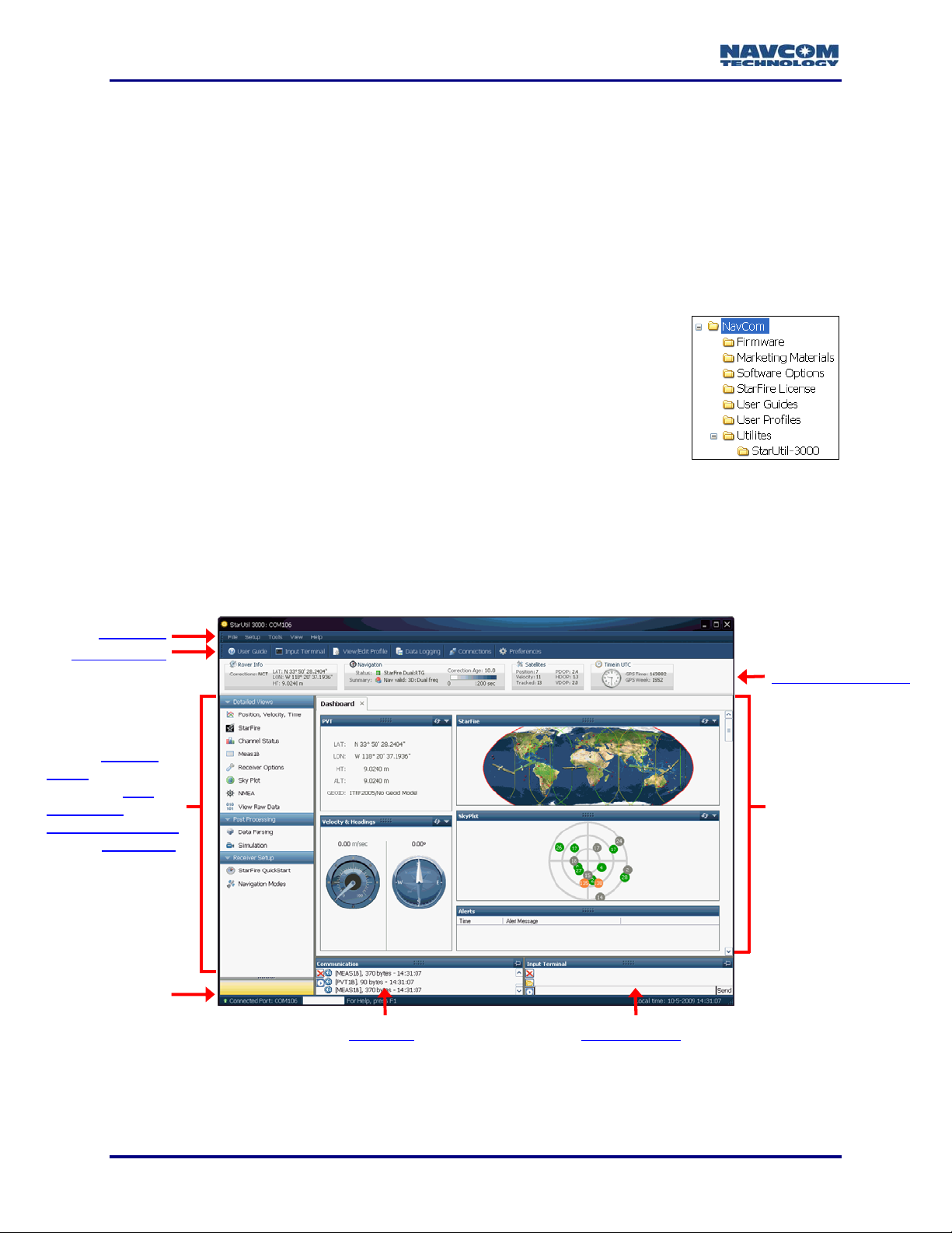
StarUtil-3000 GUI
The sections below provide general descriptions of the main parts of the GUI indentified in
Figure 2, and references to the chapters where more detailed information may be found.
Menu Bar
Short Cut Bar
Access Detailed
Views of Important
Functions, Post
Processing Tools,
StarFire QuickStart
and set Navigation
Modes
Receiver Status Bar
Main Pane
,
Status Bar
1-16
Port Data
Figure 2: StarUtil-3000 GUI
Input Terminal
Page 19
StarUtil-3000 User Guide – Rev A
Window Features
How Output Data Is Polled
StarUtil-3000 displays output data in two ways:
Data is continuously updated for some scheduled messages, for example, on the Channel
Status and MEAS1B tabs. StarUtil-3000 does not automatically poll the receiver for content.
The user must schedule these message types for output to view continuously updated data.
Some windows allow the user to poll for data to populate the window. The user clicks the
Refresh button.
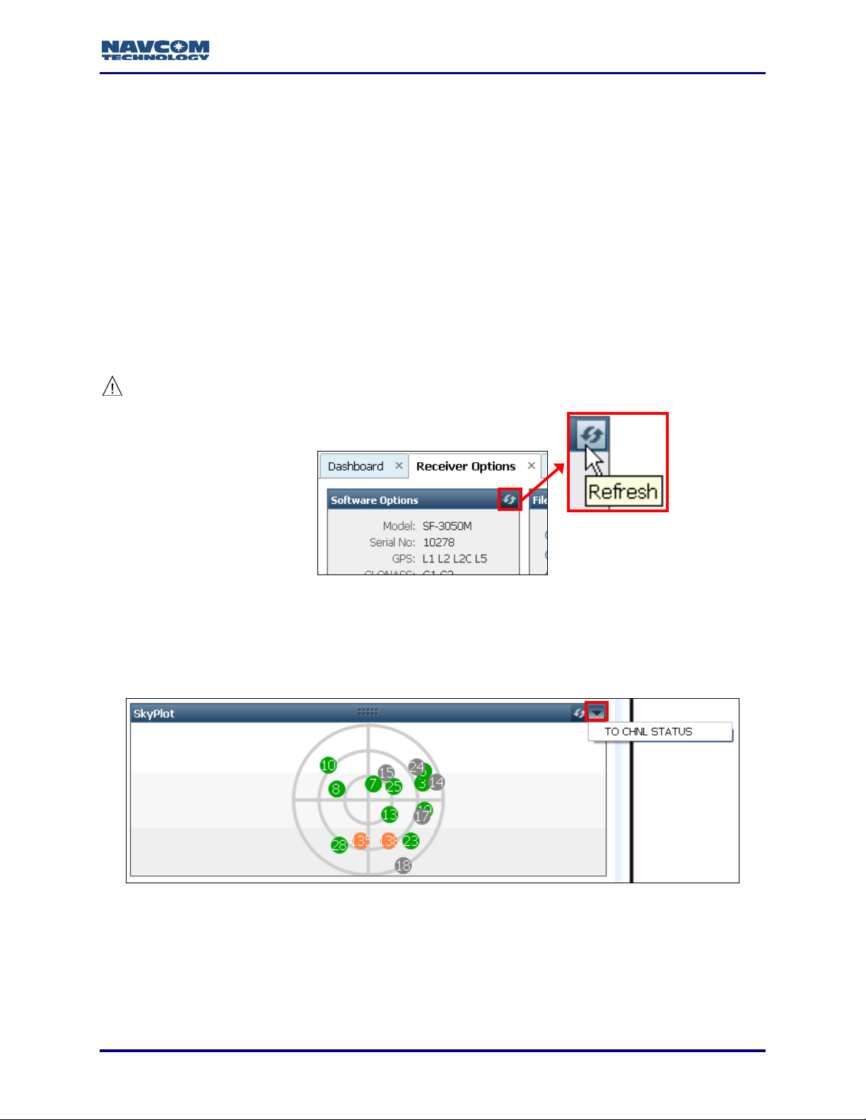
Refresh Button
Click the Refresh button
For example, after the upload of the Software Options file, click the Refresh button on the
Software Options window to ensure that the window displays the loaded options (see Figure 3).
to poll the receiver once and view the current output data in a window.
The use of the Refresh button is important to ensure that a window displays
current output data.
Figure 3: Refresh Button
Menu Button
The Menu button is a do
The option in the example pop-up menu in Figure 4 switches the view from the Sky Plot window
to the Channel Status ta
wn arrow in the top right corner of a window. It opens a pop-up menu.
b.
Figure 4: Menu Button
1-17
Page 20
StarUtil-3000 User Guide – Rev A
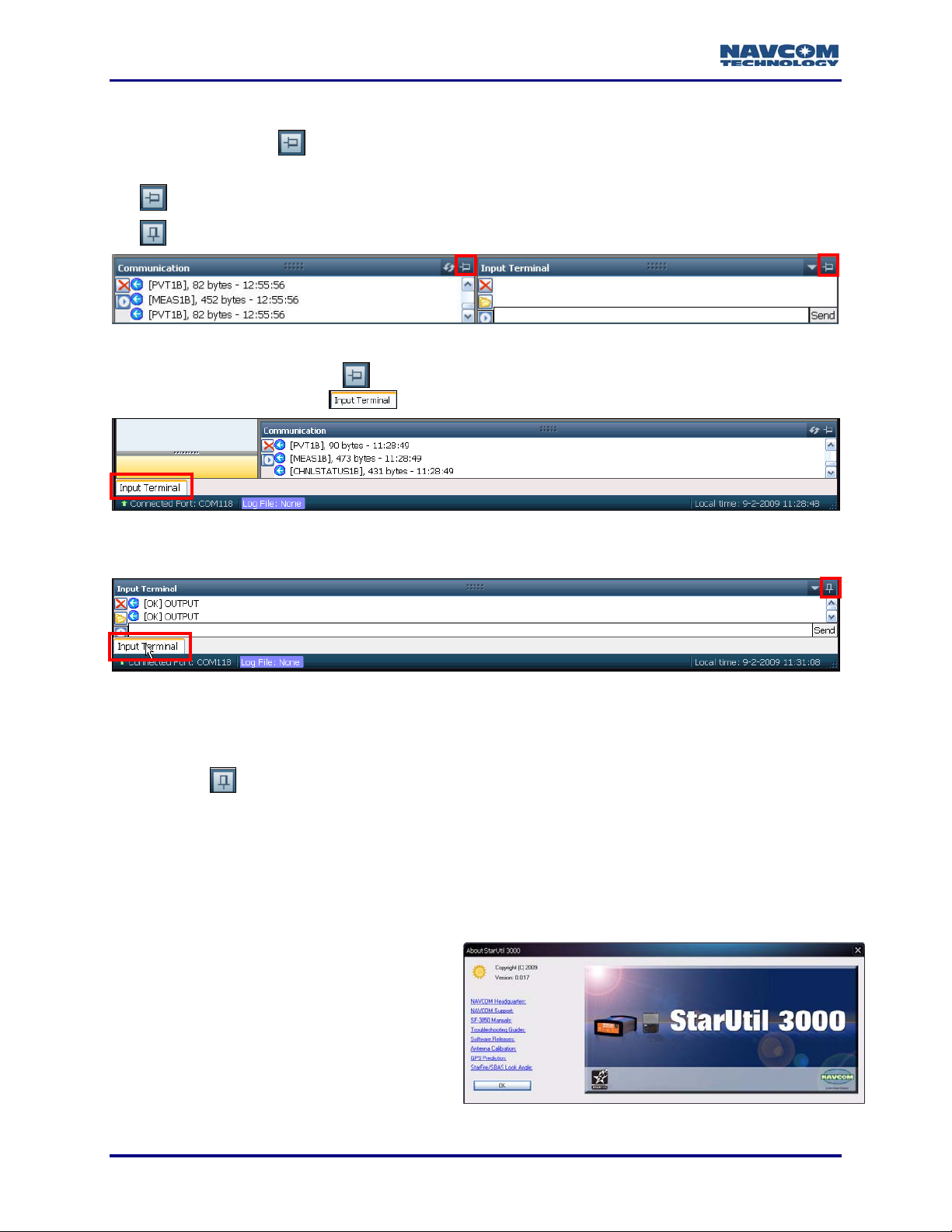
Auto Hide Button – Communication and Input Terminal Windows
The Auto Hide button
right corner (see Figure 5). It has two functions:
1. Click the Auto Hide button
2. Roll over the tab in the lower left corner of the GUI to open the hidden window (see Figure 7).
Hide Window
Return Window to Default Location
the window, for example
is only on the Communication and Input Terminal windows, in the top
Figure 5: Auto Hide Button
to hide the window. The window closes. A tab with the name of
, appears in the lower left corner of the GUI (see Figure 6).
Figure 6: Input Terminal Window Hidden
Figure 7: Cursor On Tab Opens Hidden Window
The Input Terminal button on the Short Cut Bar also opens the Input Terminal
window when it is hidden (see Figure 9).
3. Click
the
default location.
button in the top right corner on the open window. The window returns to its
Menu Bar
Not all menu options are described below.
Help
Provides access to the
Guide and the Sapphire Technical
Reference Manual (see Related D
in the fore-matter). The menu item, About
StarUtil-3000, opens the splash-screen that
appears when the program opens. It
contains version information and useful link
to NavCom support, user guides, software
releases, and tools (see
StarUtil-3000 User
ocuments
s
Figure 8).
1-18
Figure 8: About StarUtil 3000
Page 21
Short Cut Bar
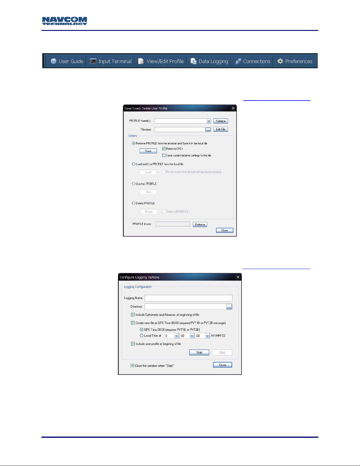
View/Edit Profile
StarUtil-3000 User Guide – Rev A
Figure 9: Short Cut Bar
Provides access t
Datalogging
ess to the
User Profile controls (see Figure 10). Refer to Chapter 6 User Profiles
o the
Figure 10: Save/Load/Delete User Profile
Datalogging controls (see Figure 11). Refer to Chapter 10 DataloggingProvides acc
.
.
Figure 11: Configure Logging Options
1-19
Page 22
StarUtil-3000 User Guide – Rev A
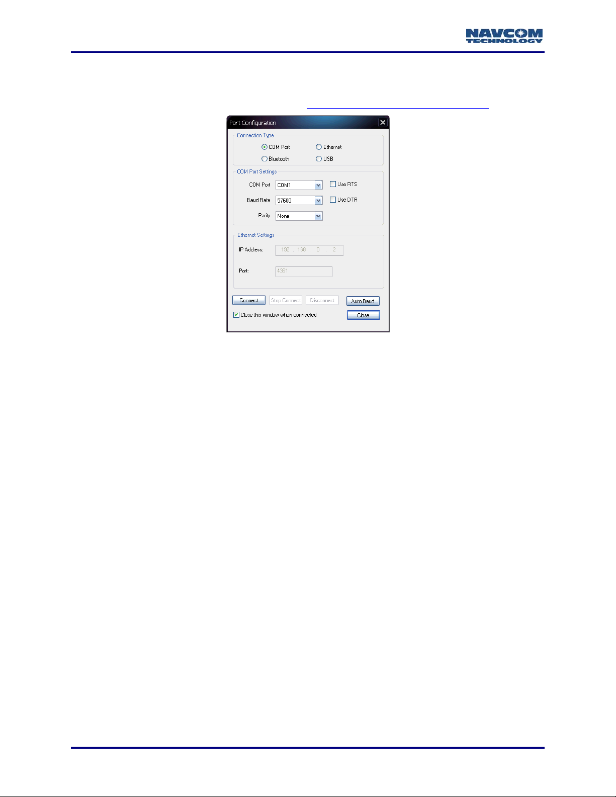
Connections
Provides access to port settings and connection to the SF-3050 via the PC’s COM Port, USB,
Bluetooth, or Ethernet (see Figure 12). Refer to Chapter 2 Establish Communications
.
Preferences
In future versions of Star
program.
Figure 12: Port Configuration Window
Util-3000, will allow the user to set custom views or layouts of the GUI
1-20
Page 23
StarUtil-3000 User Guide – Rev A
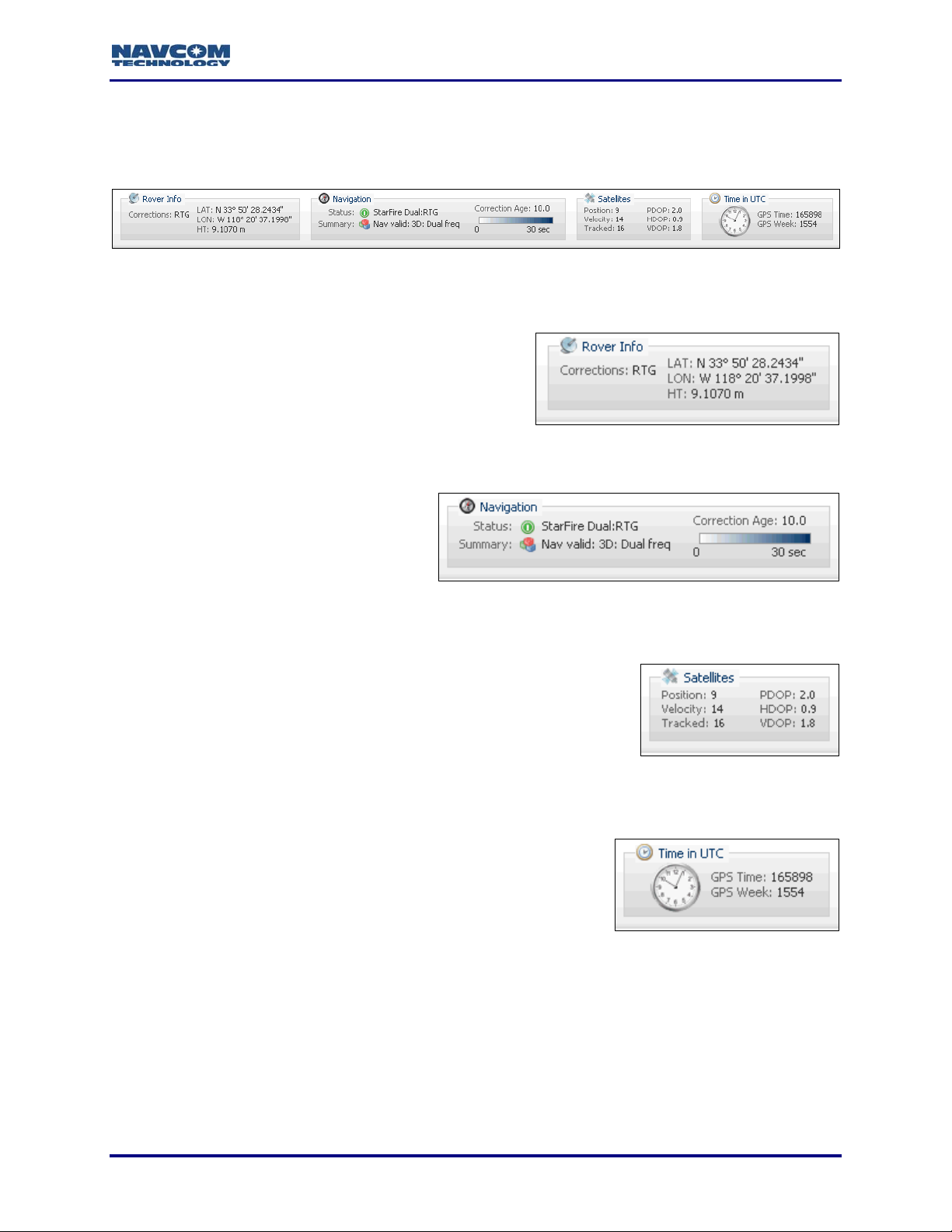
Receiver Status Bar
The Receiver Status Bar is always visible near the top of the GUI to provide a quick reference of
the current status of the receiver (see Figure 13).
Figure 13: Receiver Status Bar
Base/Rover Info
Provides the Correction Format and LAT, LON, a
nd
HT of the Base or Rover. The box heading is Base
Info or Rover Info, depending on the receiver
configuration.
Navigation
Provides a quick che
ck of the Navigation
mode and Correction Age, which can be
useful in troubleshooting.
Figure 15: Navigation
Satellites
Provides useful information on the n
umber of satellites used to
calculate the position, the velocity, and the satellites tracked, plus
DOP information.
Figure 14: Rover Info
Figure 16: Satellites
Time in UTC
Provides quick acce
ss to the time, which is a useful reference.
For example, if there is a problem with position, the user can
write down the time of the problem, and then troubleshoot the
data logged at that time during post processing.
Figure 17: Time in UTC
1-21
Page 24
StarUtil-3000 User Guide – Rev A
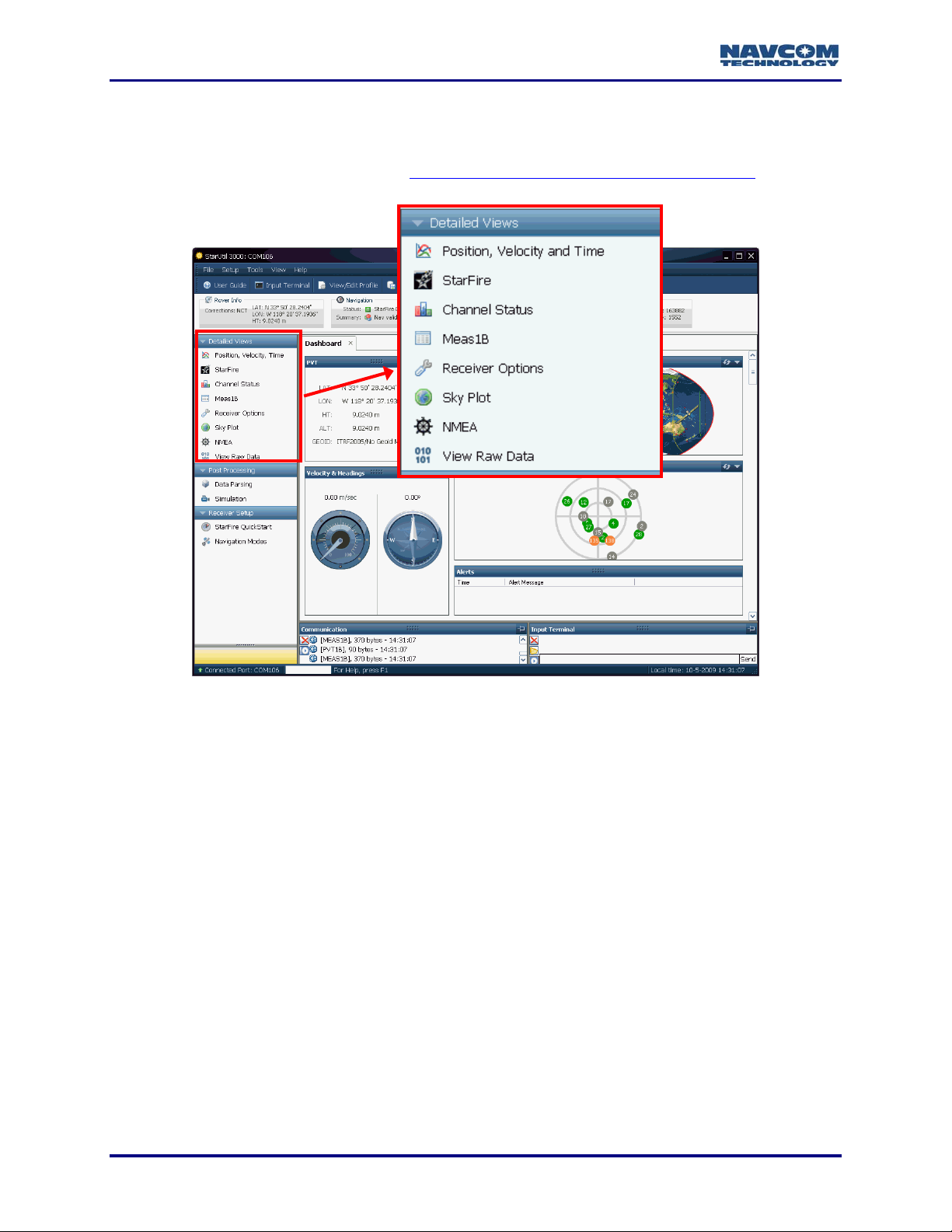
Detailed Views Menu
Provides access to detailed views of important functions (see Figure 18). Each menu item
opens a tab in the Main Pane. Refer to Chapter 9 Display of Positioning Performance
.
Figure 18: Detailed Views Menu
1-22
Page 25
StarUtil-3000 User Guide – Rev A
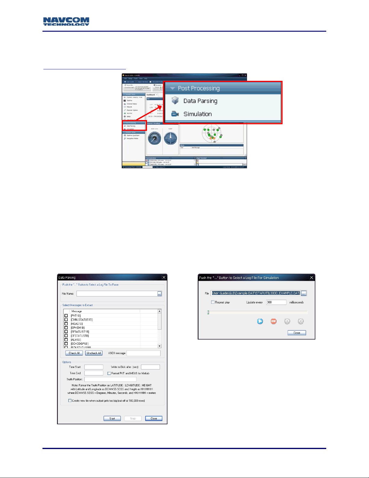
Post Processing Menu
Provides access to the Data Parsing and Simulation controls. Refer to
Chapter 11 Post Processing
Refer to Figure 20 for the controls below:
.
Figure 19: Post Processing Menu
Data Parsing
The Data Parsing wind
ow is used to extract selected NavCom proprietary messages from a
binary log file to *.txt files. Individual ASCII messages may also be extracted to a *.txt file. These
text files can be imported to other programs, such as Excel
spreadsheet software, for further
analysis or use.
Simulation
Provides a simulation of
receiver operation via the playing of a saved log file (*.DAT).
Figure 20: Data Parsing and Simulation Windows
1-23
Page 26
StarUtil-3000 User Guide – Rev A
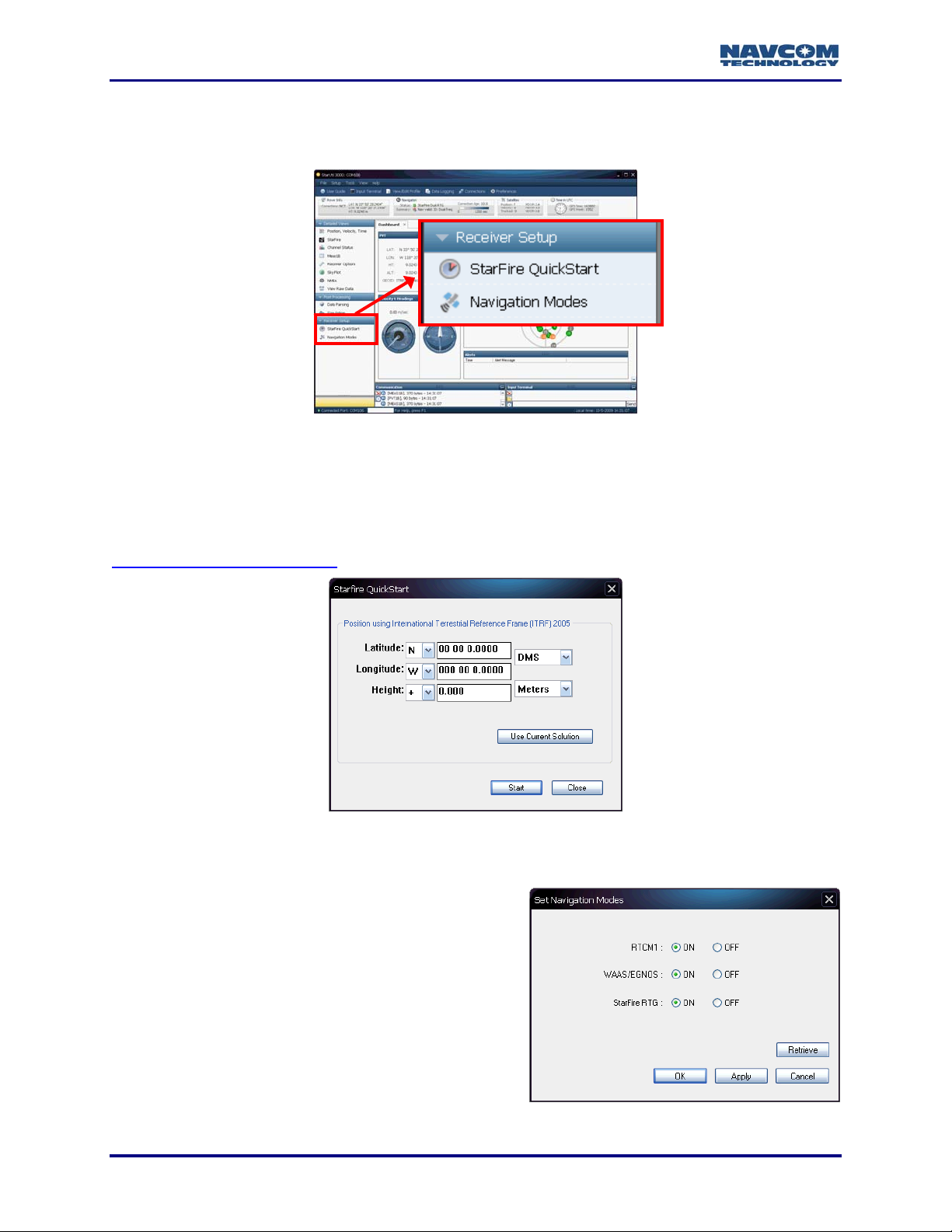
Receiver Setup Menu
Provides access to the StarFire QuickStart and Navigation Modes windows.
Figure 21: Receiver Setu
StarFire QuickStart
p Menu
StarFire QuickStart is a f
eature that eliminates the convergence period for StarFire enabled
receivers. Sub-decimeter positioning is possible in < 5 minutes. Refer to
Chapter 7/StarFire QuickStart
.
Figure 22: StarFire QuickStart Window
Navigation Modes
Provides access to navigation mode settings.
Click the Retrieve button
to retrieve the currently
set navigation modes from the receiver.
Click the ON or Off radio buttons to set the
navigation modes, and then click the Apply
button.
1-24
Figure 23: Set Navigation Modes Window
Page 27
StarUtil-3000 User Guide – Rev A
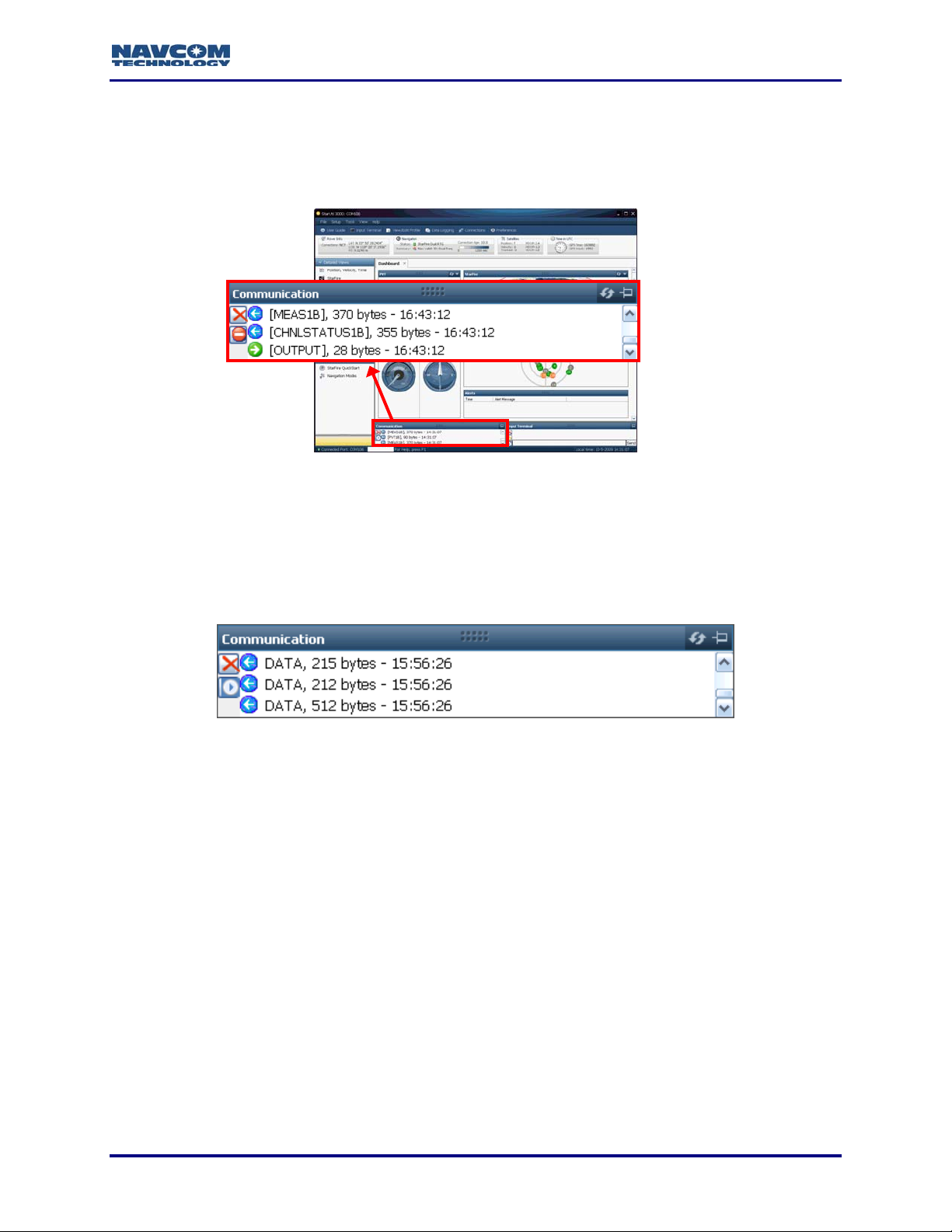
Communication Window
The Communication window displays all of the scheduled messages (see Figure 24). The
scrolling scheduled messages indicate that a valid connection is established at the correct baud
rate.
Figure 24: Co
mmunication Window – Valid Connection
A blue arrow indicates messages received by the GUI. A green arrow indicates
messages sent by the GUI.
COM Port Connection: Scrolling lines designated as “DATA” indicate a
connection is established but the receiver’s baud rate is not correct (see
Figure 25).
Figure 25: Communication Window – Connection at Incorrect Baud Rate
1-25
Page 28
StarUtil-3000 User Guide – Rev A
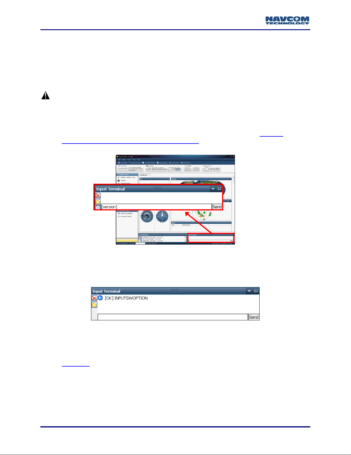
Input Terminal
Provides for the input of NavCom proprietary commands and queries. Figure 26 shows the
[version] command in the input field.
Refer to the Sapphire Technical Reference Manual for detailed information on
NavCom proprietary messages (see Related Documents in the fore-matter).
With a user profile loaded and in-use, the receiver configuration may be changed
with individual commands via the Input Terminal. Commands entered using this
technique are not saved to NVRAM through a receiver power cycle. To maintain
the new settings made through the Input Terminal window, the current settings
must be retrieved and saved as a new user profile or overwrite an existing
profile before cycling receiver power. Refer to Chapter 6 User Profiles/ Retrieve
Current Receiver Settings And Save In Local File; be sure to select the check
box in front of Save current receiver settings to the file.
Figure 26: I
nput Terminal
Input Terminal provides confirmation of actions performed via the GUI, for
instance, the upload of the Software Options file. In the example below, the file
upload is successful.
Figure 27: Input Terminal – Confirmation
The command, [USEPROFILE] “NONE”, resets all of the user-controlled
configuration parameters to the factory default values. The receiver’s profile
remains set to NONE until another profile is successfully input. Refer to
Chapter 6
The profile NONE is subject to change.
for information about user profiles.
1-26
Page 29
StarUtil-3000 User Guide – Rev A
Chapter 2 ............................................................Establish Communications
This chapter provides instructions to:
Establish communications between a PC running StarUtil-3000 and the SF-3050 via
COM1 - LAN or COM2 - USB. The SF-3050 supports RS-232/RS-422, USB 2.0, Ethernet,
and Bluetooth communications connections.
Configure and Establish Bluetooth Communications
Configure and Establish Basic Ethernet Communications
Refer to the SF-3050 GNSS Products User Guide for a list and descriptions of the
supplied and optional data cables (see Related Documents in the fore-matter).
How to Establish Serial or USB Device Communications
USB Communications: The USB driver (“navcomx1c45x3050.inf”) must be in the
same folder as StarUtil-3000 for the USB port to auto-recognize the SF-3050.
Confirm that the driver is in the StarUtil-3000 folder on the PC (see Figure 1).
In addition,
Starutil-3k_v1_0_x.exe
96-312007-3001RevX_Sapphire TRM.pdf
96-310029-3001RevX_StarUtil-3000.pdf.
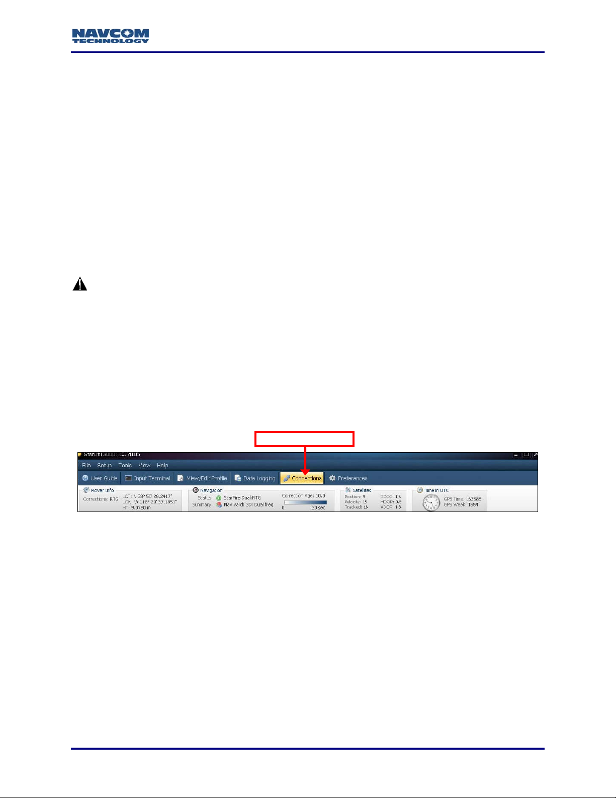
1. Click the Connections button to establish communications between the PC and the SF-3050
(see Figure 28). The Port Configuration dialog bo
ensure that these files are in the same folder:
x opens (see Figure 29).
Connections Button
Figure 28: Connections
Button
Typically, a RS-232 or USB connection is not required prior to an Ethernet
connection. This requirement exists only if:
A previous Ethernet connection was not terminated properly via the
[ETHVCOM]ON,0.0.0.0,0 command. The [ETHVCOM]ON,0.0.0.0,0 command is
included in the default system setting.
To restore the SF-3050 to the normal “listen for connection” mode so that an
Ethernet connection can be established, first establish a RS-232 or USB connection.
Then input [ETHVCOM]ON,0.0.0.0,0 via the Input Terminal window or the
appropriate user profile. The receiver will accept an Ethernet connection, or any of
these connection types: RS-232, USB, or Bluetooth.
The EVCOM port is disabled by a previous [ETHVCOM]OFF command
The EVCOM port is configured for a specific connection with a
[ETHVCOM]ON,<IP>,<port> command
2-27
Page 30
StarUtil-3000 User Guide – Rev A
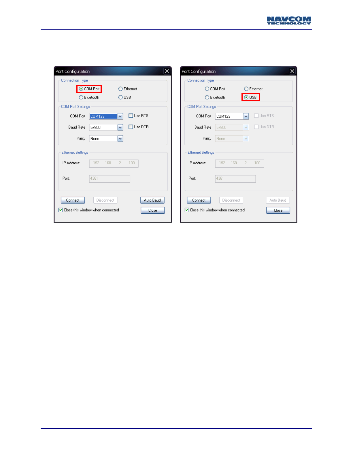
Refer to Figure 29 for the steps below:
2. Depending on the current Connection Type, do not change the default option, COM Port, or
select USB.
COM Port Settings
Figure 29: Port Configuration Dialog Box
3. Set the appropriate options according to the Connection Type:
COM Port:
COM Port: The appropriate PC COM Port
Baud Rate: 57600 (keep the default)
Parity: None (keep the default)
Or
USB Port:
COM Port: The appropriate virtual PC COM Port
USB Settings
The SF-3050 must be in “[USBMODE] Device” for this connection to work. This is
the factory default setting. Refer to the Sapphire Technical Reference Manual for
details (see Related Documents in the fore-matter).
4. Click the Connect button at the bottom of the dialog box.
5. Verify that the SF-3050 is connected to the PC. Scrolling messages in the Communication
window indicate that a valid connection is established at the required baud rate
(see Figure 30).
2-28
Page 31

StarUtil-3000 User Guide – Rev A
Figure 30: Co
mmunication Window – Valid Connection
A blue arrow indicates messages received by the GUI. A green arrow indicates
messages sent by the GUI.
COM Port Connection: Scrolling lines designated as “DATA” indicate a connection
is established but the receiver’s baud rate is not correct (see Figure 31). Open the
Port Configuration dialog
box. Click the Auto Baud button to connect.
Figure 31: Communication Window – Connection at Incorrect Baud Rate
How to Configure and Establish Bluetooth Communications
This section provides instructions to determine the Bluetooth Virtual COM port on a PC and
connect to the SF-3050 via Bluetooth.
The SF-3050 Bluetooth baud rate is fixed at 230400 baud. It will not connect at any other speed.
The data rate is 10 Hz maximum. Communications performance is dependent on the user’s
Bluetooth device.
For the initial configuration of the SF-3050, Bluetooth connectivity is not available.
Refer to the SF-3050 GNSS Products User Guide for Bluetooth compatibility (see
Related Documents in the fore-matter).
1. Write down the SF-3050 serial number from the label on the receiver.
2. Turn on the SF-3050.
3. Plug the Bluetooth dongle into the proper port on the PC.
4. Right click on the Bluetooth icon on the Windows task bar and select Explore My Bluetooth
Places from the pop-up menu. The Bluetooth window opens.
5. Click on Search for devices in range (see Figure 32). The window lists all the Bluetooth
devices within range.
2-29
Page 32

StarUtil-3000 User Guide – Rev A
Figure 32: Search for Bluetooth Devices in Range
Figure 33: Bluetooth Devices in Range
The naming convention for the SF-3050 is: SF-3050ProductTypeSerialNumber.
Example: SF-3050M10278
The SF-3050 product types are: SF-3050, SF-3050A, SF-3050G, SF-3050S, and
SF-3050M.
6. Double click on the desired SF-3050 in the Bluetooth device list (see Figure 33). A window
opens with
7. Double click on the Bluetooth serial port icon. A graphic with green arrows indicates a
connection is established between the Bluetooth Virtual COM port on the PC and the
Bluetooth dongle (see Figure 35).
a Bluetooth serial port icon for the selected receiver (see Figure 34).
Figure 34: Bluetooth Serial Port Icon
2-30
Figure 35: Bluetooth Virtual COM Port Connection
Page 33

StarUtil-3000 User Guide – Rev A
If the PC requests a Bluetooth pass code, click OK. There is no pass code for the
SF-3050 Bluetooth device.
Not all Bluetooth devices are compatible with the SF-3050. Please refer to
NavCom’s Support/Troubleshooting Guides
8. Right click on the Bluetooth serial port icon and select Properties in the pop-up menu. The
Bluetooth Properties window opens.
The window displays the Bluetooth Virtual COM port assigned to the Bluetooth dongle (see
Figure 36). Remember the COM port number for use in step 13 below.
web page for additional information.
Figure 36: Bluetooth Properties
9. Close the Bluetooth Properties window.
10. Open StarUtil-3000 on the PC.
11. Click the Connections button. The Port Configuration dialog box opens.
Figure 37: Port Configuration Windo
2-31
w – Bluetooth Settings
Page 34

StarUtil-3000 User Guide – Rev A
Refer to Figure 37 for the steps below:
12. Select Bluetooth as the Connection Type.
13. Select the appropriate COM Port (for example, COM8; see step 8 above).
14. Click
15. Verify Bluetooth connectivity:
the Connect button to connect to the SF-3050.
View the Bluetooth LED on the SF-3050 front panel. Refer to Table 2 below for
Bluetooth LED indicatio
Type [PING] in the Input Terminal and click the Send button (see Figure 38). If properly
connected, t
he response is [PING] + current port number.
Table 2: Bluetooth Connectivity LED Indications
Icon
ns.
Indicator Status Description
Bluetooth off
Bluetooth on,
no connection
Bluetooth
connected
Bluetooth
Off
Blue Blinking
Blue
Figure 38: Input Terminal – PING Command
How to Configure and Establish Ethernet Communications
The SF-3050 supports UDP connections in the initial release. Additional Ethernet connectivity is
planned in subsequent software releases as the product matures. This section only provides the
basic configuration for a direct Ethernet connection between the SF-3050 and a PC.
Ethernet cables are not supplied with the SF-3050. These Ethernet cables are available via a
NavCom authorized representative, or by contacting NavCom Sales Department
Positronic 9-Pin Male to Ethernet RJ45 Plug
(P/N 94-310265-3006LF). This cable is used in the basic configuration below.
Y-Cable, Positronic 9-Pin Male to Ethernet RJ45 Plug & DB9S (RS-232/1PPS) (P/N 94-
310272-3006LF)
:
Refer to the SF-3050 GNSS Products User Guide for a list and descriptions of
the supplied and optional data cables (see Related Documents in the forematter).
2-32
Page 35

StarUtil-3000 User Guide – Rev A
Basic Ethernet Configuration: Direct Connection Via Static IP Address
Setup
This setup uses the factory default IP address of the SF-3050:
192.168.0.2,255.255.255.0,0.0.0.0
The PC IP address is set manually in Windows.
1. Connect the Positronic 9-Pin connector of the Ethernet cable (P/N 94-310265-3006LF) to
COM1 - LAN of the SF-3050. Connect the RJ45 plug end to the computer.
2. In Windows, right click on My Network Places and select Properties from the pop-up menu.
The Network Connections window opens.
3. Right click on Local Area Connection (or the equivalent) and click Properties from the
pop-up menu. The Local Area Connection window opens.
4. Click on Internet Protocol (TCP/IP). See Figure 39.
IP Address Network Mask Gateway
Figure 39: L
ocal Area Connection Window
5. Click the Properties button. The Internet Protocol window opens.
2-33
Page 36

StarUtil-3000 User Guide – Rev A
Refer to Figure 40 for the steps below:
6. Select the option, Use the following IP address.
Figure 40: Internet Protocol Window
7. Enter the IP address for the PC. In this case, enter 192.168.0.100
The first part of the IP address, 192.168.0, is the same for the SF-3050 and the PC.
The last part of the IP address must be unique for every device. In this case, it is 100
for the PC.
8. Press the Tab button on the keyboard. The Subnet mask is automatically populated.
9. Click the OK button in this window and also in the Local Area Connection window.
10. Continue to the next section for connection instructions.
Connect SF-3050 to PC
1. Open
2. Click the Connections button to establish communications between the PC and the
Refer to Figure 41 for the steps below:
3. Select Ethernet as the Connection T
Do not change the default Ethernet Settings: 192.168.0.2 is the factory default IP
StarUtil-3000.
SF-3050 (see Figure 28). The Port Configuration
ype.
address of the SF-3050. The default virtual COM port is 4361.
dialog box opens.
2-34
Page 37

StarUtil-3000 User Guide – Rev A
Figure 41: Ethernet Port Configuration
4. Click
5. Verify that the SF-3050 is connected to the PC. Messages scrolling in the Communication
the Connect button.
window indicate that the connection is established (see Figure 30).
If an Ethernet connection is not established, use StarUtil-3000 to verify the IP
address of the SF-3050. A serial connection must be used to determine the
receiver’s IP address.
2-35
Page 38

StarUtil-3000 User Guide – Rev A
This page is left blank intentionally
2-36
Page 39

StarUtil-3000 User Guide – Rev A
Chapter 3 .......................................................................................Firmware
This chapter provides instructions to:
Determine If the Firmware Installed in the Receiver Is the Most Current
Upload Firmware to the Receiver
View Loaded Firmware
Determine If Installed Firmware Is Most Current
The most current firmware must be installed to ensure the proper operation of the
receiver.
The use of the Firmware Info window on the Receiver Options tab is the easiest way to
determine if the installed firmware is the most current. An alternative method is to use the Input
Terminal window. Both methods are described below.
Determine Firmware Versions – Receiver Options Tab/Firmware Info Window
1. Click Receiver Options in the Detailed Views menu. The Receiver Options tab opens (see
Figure 42).
Figure 42: Access to Receiver Options Tab
2. Click the Refresh button
on the Firmware Info window to view the current output data.
The firmware is identified by version number. For example, the NAV firmware
displayed in Figure 43 is version 01.00.00.003.
NAV Firmware Version
Click the
Refresh
Button
Figure 43: Exam
3-37
ple of Installed Firmware
Page 40

StarUtil-3000 User Guide – Rev A
3. Browse to the NavCom\Firmware folder on the PC (see Figure 1). The Firmware folder is
copied from the SF-3050 Product Configuration USB Flash Drive. It contains the most
current firmware (see example files in Figure 44). The firmware file extension is *.s19.
NAV Firmware
Figure 44: F
4. Compare the current NAV Firmware version in the Firmware folder with the installed version
displayed in the Firmware Info window (see Figure 45).
irmware Folder
In the example below, the NAV firmware in the Firmware folder is more current than
the installed firmware. As a result, the user must update the NAV firmware in the
receiver.
Figure 45: Co
5. If the NAV firmware installed in the receiver is not the most current version:
Check the versions of the other firmware.
Write down all the firmware that must be updated.
Go to the section below, Upload Firmware
Old NAV Firmware
mparing Current & Installed Firmware
Current NAV Firmware
.
Alternative Method to Determine Firmware Versions
1. Locate Input Terminal at the bottom right of StarUtil-3000 (see Figure 46).
Figure 46: Input Terminal
3-38
Page 41

StarUtil-3000 User Guide – Rev A
2. Enlarge the Input Terminal window by dragging the top edge of the window up.
3. Type [VERSION] in the field at the bottom of Input Terminal (see Figure 47).
Figure 47: Version Command
4. Click
the Send button. The receiver returns a list of the currently installed firmware.
The firmware is identified by version number. For example, the NAV firmware
displayed in Figure 48 is version 01.00.00.003.
NAV Firmware Version
Figure 48: Exam
5. Browse to NavCom\Firmware on the PC (see to Figure 1). The Firmware folder contains the
most current firmware. T
6. Compare the current NAV Firmware version in the Firmware folder with the installed version
displayed in the Input Terminal window (see Figure 49).
he firmware file extension is *.s19.
ple of Installed Firmware
In the example below, the NAV firmware in the Firmware folder is more current than
the installed firmware. As a result, the user must update the NAV firmware in the
receiver.
Figure 49: Co
3-39
Old NAV Firmware
mparing Current & Installed Firmware
Current NAV Firmware
Page 42

StarUtil-3000 User Guide – Rev A
7. If the NAV firmware installed in the receiver is not the most current version:
Check the versions of the other firmware.
Write down all the firmware that must be updated.
Go to the section below to upload firmware.
Upload Firmware
PC Baud Rate Requirements for Firmware Upload Via Serial Connection
The requirements below only apply to firmware uploaded via a Serial connection. They do not
apply to firmware uploaded via a USB 2.0 Device or Ethernet connection.
GNSS Firmware
SF-3050 COM1: The maximum PC baud rate to upload the appropriate Bootloader and the
NAV firmware file via a Serial connection is 115200.
SF-3050 COM2: The required PC baud rate to upload the appropriate Bootloader and the
NAV firmware file via a Serial connection is 57600.
PWRIO Firmware
SF-3050 COM2: The maximum PC baud rate to upload the PWRIO Bootloader and the
PWRIO firmware file via a Serial connection is 115200.
SF-3050 COM1: the required PC baud rate to upload PWRIO firmware via a Serial
connection is 57600.
Upload Firmware
The receiver must be navigating at the time of the firmware upload.
Typically, if any firmware needs to be updated, it is NAV and PIOAPP.
1. Click Receiver Options in the Detailed Views menu. The Receiver Options tab opens (see
Figure 50).
3-40
Figure 50: Receiver Options
Page 43

StarUtil-3000 User Guide – Rev A
2. Select GNSS Receiver Firmware in the File Upload window (see Figure 51).
Figure 51: File Upload Window – GNSS Receiver Firmware
3. Click the
4. Click the
5. Browse to NavCom\Firmware on the PC or USB flash drive (see Figure 53).
button.
button. The Load Receiver Firmware window opens (see Figure 52).
Figure 52: Load Receiver Firmware Window
Figure 53: Firmware Folder
6. Select the appropriate firmware file.
Upload Boot files before application files if both types require updating.
Example Boot File: SP_boot2_ver1,0,4.s19
The format of the NAV firmware file is:
SPv + version number.s19
Example NAV File: SPv1,0,0,4.s19
3-41
Page 44

StarUtil-3000 User Guide – Rev A
7. Set these options:
Baud Rate:
Serial Connection: Refer to the section above, PC Baud Rate Requirements for
Firmware Upload Via Serial Connection.
USB 2.0 Device or Ethernet Connection: No selection is necessary. The speed of the
connection is automatically set.
Figure 54: Settings For GNSS Firmware
Target:
Select SOLARIS to upload GNSS firmware (see Figure 54):
SP_boot1_[version number].s19
SP_boot2_[version number].s19
SPv[version number].s19
Or
Select SOLARIS PIO to upload PWRIO firmware (see Figure 55):
SP_PWRI
Oboot1_[version number].s19
SP_PWRIO_[version number].s19
Bootloader: Do not set this option. The program automatically sets the buffer type.
Force Load Firmware Without PING: Keep the default (unchecked).
Figure 55: Settings For
PWRIO Firmware
8. Click the Load button. An upload progress window opens. At the end of upload, a
confirmation box opens. Click OK.
9. Repeat the steps above to upload more firmware files if necessary.
3-42
Page 45

StarUtil-3000 User Guide – Rev A
Chapter 4 ....................................................................... Geoidal Databases
This chapter provides instructions to:
Determine whether or not a geoidal database, GGM02 or a user-defined Geoid Height Map,
is loaded in the receiver
Upload the GGM02 database or a user-defined Geoid Height Map (identified as GEOID99 in
StarUtil-3000)
In addition, this chapter provides the GEOIDAL99 format and file requirements.
User-defined Geoid Height Maps are based on the GEOIDAL99 format.
Refer to the Sapphire Technical Reference Manual for detailed information on the
commands used in this chapter: [GEOIDALMODEL] and [GGM02STATUS] (see
Related Documents in the fore-matter).
Determine If Geoid Model Is Loaded
No Geoid Model Is Loaded
Figure 56: PVT Window – GEOID
Refer to Figure 56 for the steps below:
GGM02 Is Loaded
GEOID99 Is Loaded
The GEOID status displayed on the PVT window has 3 possible values:
No Geoid Model, GGM02, or GEOID99 (user-defined geoidal database). Refer to
the section below, Geoid Height Map
View the PVT window on either the Dashboard or the PVT tab to determine if the GGM02 or
a GEOID99 database is loaded in the receiver. Click the Refresh button
the most current data is displayed in the window.
If No Geoid Model is displayed, go to these sections to upload a geoidal database if desired:
Upload The GGM02 Database
Upload A User-Defined Geoid Height Map
, for information on the GEOIDAL99 format.
to ensure that
If No Geoid Model is displayed, the Height and Altitude in the PVT window are the same.
If the GGM02 or GEOID99 database is loaded, the Height and Altitude typically differ.
The Input Terminal window can also be used to determine which geoidal model,
if any, is loaded in the receiver. Input [GEOIDALMODEL] to query the currently
selected geoidal database. In addition, the [GGM02STATUS] command may be
input to query the GGM02 database status in the receiver (see Figure 57).
4-43
Page 46

StarUtil-3000 User Guide – Rev A
Figure 57: Input Terminal – [GGM02STATUS] Command and Response
Upload The GGM02 Database
GGM02 stands for GRACE Gravity Model 02. It is derived from data recorded by
the Gravity Recovery And Climate Experiment (GRACE). This model is used to
compute geoidal separation, the difference between the WGS-84 earth ellipsoid
and mean-sea-level (geoid).
1. Click Receiver Options in the Detailed Views menu. The Receiver Options tab opens (see
Figure 58).
Figure 58: Receiver Options
2. Select Load GGM02 in the File Upload window (see Figure 59).
3. Click the
Figure 60).
Figure 59: F
button. The Load GRACE Gravity Model 02 window opens (see
ile Upload Window – Load GGM02
Figure 60: Load GGM02 Window
4-44
Page 47

StarUtil-3000 User Guide – Rev A
4. Ensure that Restart receiver after loading (default) is checked so that the receiver will
perform a warm start (resets the receiver) after the upload is successful. (The user receives
no indication of the warm start. It is a background process.)
5. Click the Start Loading button. An upload progress window opens. At the end of upload, a
confirmation box opens. Click OK.
6. Type [GEOIDALMODEL]GGM02 in Input Terminal and click the Send button (see
Figure 61).
Figure 61: [GEOIDALMODEL]GGM02 Command and Response
7. View the PVT window on either the Dashboard or the PVT tab to confirm the successful
upload. GGM02 is identified as the current GEOID (see Figure 56).
GGM02 is not maintained as the Geoid Model through a receiver power cycle in
version 1.0.0.4 navigation firmware. This is corrected in later versions of
firmware. To reset GGM02 as the Geoid Model, reload the appropriate user
profile or input [GEOIDALMODEL]GGM02 via the Input Terminal.
Geoid Height Map
This section provides:
The GEOIDAL99 format and file requirements. The Geoid Height Map is based on the
GEOIDAL99 format.
Instructions to upload a user-defined Geoid Height Map into the receiver
The Geoid Height Map is used to obtain more precision in a small area than the
GGM02 database can provide.
The user may create the Geoid Height Map, or download a Geoid Height Map
from the NOAA web site (URL below). The total number of points in the map
must be < 262,000 (number of rows of latitude x number of columns of
longitude).
If the total number of points is 262,000, the file upload is denied (see
Figure 64). The user is responsible to extract the appropriate portion of the
original data
the NOAA web site:
set. A software extraction tool, XNTG.EXE, is also available from
http://www.ngs.noaa.gov/GEOID/GEOID99/dnldgeo99pc1.html
4-45
Page 48

StarUtil-3000 User Guide – Rev A
GEOIDAL99 Format
The GEOIDAL99 database file must be a binary file. It has a header plus a data section,
described below.
Table 3: GEOIDAL99 Header Format
Data Item Data Type Units Bytes
Header
SLAT – Southernmost latitude R64 Degrees 8
WLON – Westernmost longitude R64 Degrees 8
DLAT – Distance interval in latitude R64 Degrees 8
DLON – Distance interval in longitude R64 Degrees 8
NLAT – Number of rows of latitude U32 4
NLON – Number of columns of longitude U32 4
IKIND – Data type
The value always should be 1 (=> real *4)
U32
4
The data section of the GEOIDAL99 database file follows immediately after the header. Table 4
displays the
example,
“a
format, in which
” = 4 bytes (real number) of data at Latitude Row 3, Longitude Column 2.
R3C2
“a” represents a R32 Data Type, R = Row and C = Column. For
The data is variable length. NLAT is the total number of rows. NLON is the total number of
columns. (Table 3 defines NLAT and NLON.)
Table 4: GEOIDAL99 Data Form
1 2 3 4 NLON
1
2
3
4
… … … … …
NLAT
a
R1C1
a
R2C1
a
R3C1
a
R4C1
a
RNLATC1
a
a
a
a
a
a
R1C2
a
R2C2
a
R3C2
a
R4C2
RNLATC2aRNLATC3aRNLATC4
R1C3
R2C3
R3C3
R4C3
at (variable length)
a
a
a
a
R1C4
R2C4
R3C4
R4C4
…
…
…
…
a
R1CNLON
a
R2CNLON
a
R3CNLON
a
R4CNLON
a
RNLAT/CNLON
The data section is stored in the file beginning with the Westernmost (WLON)/Southernmost
(SLAT) point. In Table 4, this is the first point in Row 1:
“a
R1C1
”, “a
R1C2
”, “a
R1C3
”, “a
”, etc. Then Row 2 is stored: “a
R1C4
“a
”. Row 1 (row-major) is stored:
R1C1
R2C1
”, “a
R2C2
”, “a
R2C3
”, “a
R2C4
etc. This is continued sequentially for each row until the Easternmost/Northernmost point,
“a
RNLAT/CNLON
”, is stored. Each row creates a list of 4-byte real values NLON long, with DLON
longitudinal intervals along the row of latitude.
4-46
”,
Page 49

StarUtil-3000 User Guide – Rev A
Upload A User-Defined Geoid Height Map
1. Open the Receiver Options tab (see Figure 58).
2. Select Geoid Height Map in the File Upload window (see Figure 62).
Figure 62: File Upload Window – Geoid Height Map
3. Click the
Figure 63).
4. Click the
button. The Upload User-Defined Height Map window opens (see
Figure 63: Upload User-Defined Height Map Window
button.
Total Points < 262,000 Limit – Upload Permitted
Total Points 262,000 Limit – Upload Denied
Figure 64: Upload User-Defined Height Map Window – File Selected for Upload
Refer to Figure 64 for the steps below:
Browse to and select the appropriate file. The path to the file appears in the upload field.
5.
Data retreived from the file is displayed:
Southmost Latitude / Spacing (distance interval in latitude) / Rows (number of rows of
latitude)
Westmost Longitude / Spacing (distance interval in longitude) / Rows (number of
columns of longitude)
Total Points: < 262,000 limit. If the limit is exceeded, upload is denied.
4-47
Page 50

StarUtil-3000 User Guide – Rev A
6. Ensure that Restart receiver after loading (default) is checked so that the receiver will reset
(perform a warm start) after the upload is successful. (The user receives no indication of the
warm start. It is a background process.)
7. Click the Start Loading button. An upload progress window opens. At the end of upload, a
confirmation box opens. Click OK.
Ensure that the receiver has restarted from the warm start before performing the
next step. Monitor the PVT tab/Navigation Status window for a change from “Nav
invalid” to “Nav valid”. Or monitor the LEDs on the front indicator panel of the
receiver. Refer to the SF-3050 GNSS Products User Guide for details on LED
indications (see Related Documents in the fore-matter).
8. Type [GEOIDALMODEL]GEOIDAL99 in Input Terminal and click the Send button (see
Figure 65).
Figure 65: [GEOIDALMODEL] GEOIDAL99 Command and Response
9. View the PVT window on either the Dashboard or the PVT tab to confirm the successful
upload. GEOID99 is identified as the current GEOID (see Figure 56).
The Geoid Height Map (GEOID99) is not maintained as the Geoid Model through
a receiver power cycle in version 1.0.0.4 navigation firmware. This is corrected in
later versions of firmware. To reset the Geoid Height Map as the Geoid Model,
reload the appropriate user profile or input [GEOIDALMODEL]GEOIDAL99 via
the Input Terminal.
4-48
Page 51

StarUtil-3000 User Guide – Rev A
Chapter 5 .......................................................................... Software Options
This chapter provides instructions to upload Software Options to enable the robust functionality
of the SF-3050 in the initial configuration purchased by the user, or as a performance upgrade.
The SF-3050 is designed with a long-term performance upgrade path to meet changing needs
via software upgrades. Increased functionality does not typically require the costly purchase of
additional hardware.
The SF-3050 software-enabled features, bundled or purchased individually,
cover a wide variety of applications. Refer to the SF-3050 GNSS Products User
Guide for descriptions of the software options in each bundle: SF-3050G,
SF-3050S, and SF-3050M.
For the initial setup of the SF-3050, Software Options must be loaded before the
StarFire License (if purchased).
How to Purchase Software Options
Contact a NavCom authorized representative, or the NavCom Sales Department
(sales@navcomtech.com) to purchase software options.
The options code is receiver dependant and cannot be uploaded into multiple
receivers. Archive the software options file in case a reload is necessary.
Upload Software Options
The receiver must be navigating at the time of the software options upload.
1. Click Receiver Options in the Detailed Views menu (see Figure 50). The Receiver Options
tab opens.
Refer to Figure 66 for the steps below:
2. Locate
the radio button next to Software Options if it is not selected.
3. Click the
4. Browse to NavCom\Software Options on the PC (see Figure 1). The Software Options file
extension is
example “SN123452”.
5. Select the Software Options file. The path to the file appears in the upload field.
the File Upload window on the tab. Software Options is the default file upload. Click
button.
*.opt. Each file includes the specific SF-3050 serial number in the file name, for
Figure 66: Software Options Upload
5-49
Page 52

StarUtil-3000 User Guide – Rev A
6. Click the Upload button. At the end of upload, a confirmation box opens. Click OK.
The Input Terminal window also displays the outcome of the upload. In the
example below, the upload is successful.
Figure 67: Input Terminal – Successful Software Upload
7. Click the Refresh button on the Software Options window (see Figure 68). This ensures that
the loaded
Software Options are displayed in the window.
If any of the purchased Software Options are not displayed in the Software
Options window, contact the authorized dealer or NavCom Customer Support
immediately.
“StarFire: Enabled” indicates that the StarFire Software Option is loaded. It does
not indicate that a StarFire License is installed. Refer to
Chapter 7/StarFire License Data
confirmation of an installed StarFire License.
for descriptions of the windows that provide
5-50
Figure 68: Software Options Window – Refresh Button
Page 53

StarUtil-3000 User Guide – Rev A
1
RTK Extend
RTK Extend1 is a purchased software option for Navcom StarFire receivers, such as the
SF-3050. It enables continuous real-RTK/RTK level positioning accuracy during radio
communication outages by utilizing NavCom’s global StarFire corrections.
Enable RTK Extend
To enable RTK Extend:
RTK Extend Software Option: A valid RTK Extend Software Option must be installed in
the rover (see Figure 68)
Set Navigation Modes Window: “StarFire RTG” must be set to ON (see Figure 90)
Verify RTK Extend Is Active
To verify that RTK Extend is active during a radio communication outage:
1. Ensure that RTK Extend is enabled (see the section above).
2. Allow the receiver to obtain a RTK fix and verify that the StarFire signals are under track
(refer to Chapter 7/StarFire Performance
operation. Once both of these conditions are met, turn off or disconnect the RTK radio
modem.
). This typically occurs about 4 minutes into
3. Determine if RTK Extend is active on the PVT tab/Navigation Status window. RTK Extend is
active if the rover’s Nav Mode is: RTK X:StarFire RTG.
RTK Extend is not active if the rover’s Nav Mode is: RTK X:Unknown.
The Position FOM follows the StarFire Dual:RTG: 3D: Dual freq navigation mode,
but the positioning accuracy will stay at RTK levels (approx. 1cm) during the RTK
Extend period. View the Position FOM on the PVT Tab/Error Estimates Window
(see Figure 119).
Not Standard in Software Bundles
5-51
Page 54

StarUtil-3000 User Guide – Rev A
This page is left blank intentionally
5-52
Page 55

StarUtil-3000 User Guide – Rev A
Chapter 6 ................................................................................. User Profiles
This chapter provides guidance to load, create, view (verify the profile in use), edit, save, and
delete User Profiles.
The SF-3050 utilizes individual commands, input via the Input Terminal, or groups of
commands, known as User Profiles, to set the various port assignments/parameters, navigation
parameters, and output message lists.
With a user profile loaded and in-use, the receiver configuration may be changed
with individual commands via the Input Terminal. Commands entered using this
technique are not saved to NVRAM through a receiver power cycle. To maintain
the new settings made through the Input Terminal window, the current settings
must be retrieved and saved as a new user profile or overwrite an existing
profile before cycling receiver power. Refer to the section below in this chapter,
Retrieve Current Receiver Settings And Save In Local File
check box in front of Save current receiver settings to the file.
The SF-3050 provides for storage of up to 20 user profiles. Profiles may also be stored on a
PC. Each user profile is stored with a name. The user profile extension is *.npt.
StarUtil-3000, or another controller solution, is used to upload a user profile by its name.
; be sure to select the
The SF-3050 may be initially configured with the factory default user profile or a profile
customized for the user by an authorized dealer.
Predefined, commonly-used profiles are included on the supplied SF-3050 Product
Configuration USB Flash Drive or available by email.
Refer to the Sapphire Technical Reference Manual for detailed information on the
[PROFILE] and [USEPROFILE] commands (see Related Documents in the
fore-matter).
To open the Save/Load/Delete User Profile window, click the button
near the top of the GUI.
How User Profiles Work
A new profile sent to the receiver replaces the currently used profile, but it does not necessarily
replace all the current parameter settings. The new profile replaces only those parameter
settings that it specifies.
For example:
The default navigation elevation mask is 7.
The user changes the elevation mask to 12 in a profile named “Test”. The user subsequently
sends profile “RTK” to the receiver. It replaces “Test”, and changes navigation mode settings
and port assignments.
But profile “RTK” does not specify a setting for the navigation elevation mask. So, the elevation
mask remains at 12, as previously set by the “Test” profile.
6-53
Page 56

StarUtil-3000 User Guide – Rev A
Profile NONE
The command, [USEPROFILE] “NONE”, resets all of the user-controlled configuration
parameters to the factory default values. The receiver’s profile remains set to NONE until
another profile is successfully input.
Refer to the section below Factory Default Output Messages.
The profile NONE is subject to change.
Creating A User Profile
This section provides guidance in the creation of a user profile.
The example user profile below configures a receiver to use the StarFire Subscription Service.
Port 1 is the control port. In the example user profile:
The settings directly related to StarFire are highlighted in yellow.
The commands related to navigation performance and [OUTPUT] depend upon specific
application requirements.
Although the receiver in this example is not a Base or Rover, the user profile includes RTK
settings. This is because it is useful to create profiles that can be easily adapted to other
application requirements. Refer to Chapter 8 RTK Setup
for an example user profile
configured for RTK.
Refer to the Sapphire Technical Reference Manual for detailed information on the
commands and output streams in the example user profile below (see Related
Documents in the fore-matter).
Refer to Chapter 7 StarFire Operation for StarFire licensing and software requirements.
[NAVELEVMASK]7.00
[STARFIREALTSAT]OFF
[TRACKINGMODE]L1,ON,L2,ON,L2C,ON,L5,OFF,WAASEGNOS,ON,STARFIRE,ON,G1,ON,G2,ON
[NAVMEASUSE]L1,ON,L2,ON,L2C,ON,L5,OFF,WAASEGNOS,ON,GLONASS,ON
[GEOIDALMODEL]GGM02
[REFNAME]"NAVCOMREF1"
[OUTPUT]NONE,,,-1
[OUTPUT]??,ONCHANGE,,1
[OUTPUT]OK,ONCHANGE,,1
[OUTPUT]PANICA,ONCHANGE,,1
[OUTPUT]PVT1B,ONTIME,0.1,1
[OUTPUT]MEAS1B,ONTIME,0.1,1
[OUTPUT]EPHEM1B,ONCHANGE,,1
[OUTPUT]ALM1B,ONCHANGE,,1
[OUTPUT]ECHODGPSB,ONCHANGE,,1
[OUTPUT]WAASDATAB,ONCHANGE,,1
[OUTPUT]TXRXINFOA,ONCHANGE,,1
[OUTPUT]NAVSTATUSA,ONCHANGE,,1
[OUTPUT]CHNLSTATUS1B,ONTIME,1,1
[OUTPUT]SFSTATUS1B,ONCHANGE,,1
[OUTPUT]RTKSTATUS1B,ONCHANGE,,1
[OUTPUT]RTKSTATUS2B,ONCHANGE,,1
[OUTPUT]PHASENAVSTATUS1B,ONCHANGE,,1
[OUTPUT]CODENAVSTATUS1B,ONCHANGE,,1
[OUTPUT]NAVCONFIG1B,ONCHANGE,,1
Continued on next page…
6-54
Page 57

Putting the Port baud
rate settings at the
end of all user profiles
is recommended.
Refer to the section
below, Avoiding User
Profile Loading
Errors, for details.
StarUtil-3000 User Guide – Rev A
[OUTPUT]SFLICENSEB,ONCHANGE,,1
[OUTPUT]MSGCANCELHISTORYB,ONCHANGE,,1
[OUTPUT]MSGCANCELCODESB,ONCHANGE,,1
[OUTPUT]??,ONCHANGE,,2
[OUTPUT]OK,ONCHANGE,,2
[OUTPUT]PANICA,ONCHANGE,,2
[OUTPUT]??,ONCHANGE,,3
[OUTPUT]OK,ONCHANGE,,3
[OUTPUT]PANICA,ONCHANGE,,3
[OUTPUT]??,ONCHANGE,,BT
[OUTPUT]OK,ONCHANGE,,BT
[OUTPUT]PANICA,ONCHANGE,,BT
[OUTPUT]??,ONCHANGE,,4
[OUTPUT]OK,ONCHANGE,,4
[OUTPUT]PANICA,ONCHANGE,,4
[OUTPUT]??,ONCHANGE,,USB1
[OUTPUT]OK,ONCHANGE,,USB1
[OUTPUT]PANICA,ONCHANGE,,USB1
[OUTPUT]??,ONCHANGE,,USB2
[OUTPUT]OK,ONCHANGE,,USB2
[OUTPUT]PANICA,ONCHANGE,,USB2
[OUTPUT]??,ONCHANGE,,FH1
[OUTPUT]OK,ONCHANGE,,FH1
[OUTPUT]PANICA,ONCHANGE,,FH1
[OUTPUT]??,ONCHANGE,,FH2
[OUTPUT]OK,ONCHANGE,,FH2
[OUTPUT]PANICA,ONCHANGE,,FH2
[OUTPUT]??,ONCHANGE,,ETH1
[OUTPUT]OK,ONCHANGE,,ETH1
[OUTPUT]PANICA,ONCHANGE,,ETH1
[OUTPUT]??,ONCHANGE,,ETH2
[OUTPUT]OK,ONCHANGE,,ETH2
[OUTPUT]PANICA,ONCHANGE,,ETH2
[2DNAVMODE]AUTO,0.0000
[PDOPLIMIT]10.0
[RTKTIMEOUT]15.0
[RTKFLOATTIMEOUT]300
[RTKMODE]rover,NCT,1
[PRDGPSMODE]RTCM1,OFF
[PRDGPSMODE]WAASEGNOS,ON
[PRDGPSMODE]SFRTG,ON
[PRDGPSTIMEOUT]RTCM1,300
[PRDGPSTIMEOUT]WAASEGNOS,300
[PRDGPSTIMEOUT]SFRTG,1200
[REFSTNPOS]0,0,0.000000,0,0,0.000000,0.000000
[L1FALLBACK]OFF
[PORT]2,19200,8,1,NONE
[PORT]3,57600,8,1,NONE
[PORT]4,57600,8,1,NONE
[PORT]1,115200,8,1,NONE
Figure 69: Example User Profile – StarFire Configuration
6-55
Page 58

StarUtil-3000 User Guide – Rev A
Typical Commands And Parameters In User Profiles
Refer to the Sapphire Technical Reference Manual for the complete set of commands
and output streams utilized by the SF-3050 receiver (see Related Documents in the
fore-matter).
See also Chapter 8 RTK Setup for guidance to set up typical Base and Rover RTK
configurations.
[NAVELEVMASK]
This command sets the l
navigation solution. Measured from the horizon to zenith, 0º to 90º.
[TRACKINGMODE]
This command is used t
frequencies. When a GPS signal or frequency is enabled or disabled, it applies to all GPS
satellites broadcasting that signal.
owest elevation, in degrees, at which a receiver uses a satellite in the
o enable or disable the receiver’s tracking of various signals or
Enabling a specific tracking mode is necessary to allow the receiver to acquire
and track the signal, but it is not sufficient. The receiver must also be licensed for
that tracking mode, and the signal must be available.
In areas where the receiver can track SBAS signals for regions other than where
the receiver is located (i.e., the receiver is in Malaysia tracking the Japanese
MSAS satellite), [TRACKINGMODE] allows the user to disable tracking the
SBAS satellite signal, which would otherwise cause positioning errors. In
addition, the user may disable the SBAS satellite signal via the Set Navigation
Mode window (see Figure 112).
[NAVMEASUSE]
This command is used t
for navigation. When a GPS signal or frequency is enabled or disabled, it applies to all GPS
satellites broadcasting that signal.
o enable or disable the receiver’s use of various signals or frequencies
Enabling a specific measurement is necessary to allow the receiver to use the
signal measurement, but it is not sufficient. The receiver must also be licensed
for that tracking mode, and the signal must be available.
L1 measurement usage is critical to the operation of the receiver. The disabling
of the L1 measurement (L1,OFF) places the receiver in an “undefined
configuration” which may produce unpredictable results.
In areas where the receiver can track SBAS signals for regions other than where
the receiver is located (i.e., the receiver is in Malaysia tracking the Japanese
MSAS satellite), [TRACKINGMODE] allows the user to disable tracking the
SBAS satellite signal, which would otherwise cause positioning errors. In
addition, the user may disable the SBAS satellite signal via the Set Navigation
Mode window (see Figure 112).
6-56
Page 59

StarUtil-3000 User Guide – Rev A
[TRACKINGMODE] And [NAVMEASUSE]
In regard to both the [TRACKINGMODE] and [NAVMEASUSE] commands, tracking of newer
navigation satellite signals (L2C, L5, E1, and E5A) is subject to:
The availability of the signals from newer satellites
The "health bit" set to "healthy"
The SF-3050 navigation software updated to a version compatible with the signals
The user must choose to track either L5 or G2.
[OUTPUT]NONE,,,-1
This command is listed at the beginning of the [OUTPUT] commands in a user profile (see
Figure 70). It deletes all the Outputs currently stored in the receiver. Then the Outputs in the
new user profile are loa
ded.
The use of [OUTPUT]NONE,,,-1 ensures that none of the Outputs in the old user profile remain
stored in the receiver. Refer to the section above, How User Profiles Work.
[NAVELEVMASK]7.00
[STARFIREALTSAT]OFF
[TRACKINGMODE]L1,ON,L2,ON,L2C,ON,L5,OFF,WAASEGNOS,ON,STARFIRE,ON,G1,ON,G2,ON
[NAVMEASUSE]L1,ON,L2,ON,L2C,ON,L5,OFF,WAASEGNOS,ON,GLONASS,ON
[GEOIDALMODEL]GGM02
[REFNAME]"NAVCOMREF1"
[OUTPUT]NONE,,,-1
[OUTPUT]??,ONCHANGE,,1
[OUTPUT]OK,ONCHANGE,,1
[OUTPUT]PANICA,ONCHANGE,,1
[OUTPUT]PVT1B,ONTIME,0.1,1
[OUTPUT]MEAS1B,ONTIME,0.1,1
[OUTPUT]EPHEM1B,ONCHANGE,,1
Figure 70: [OUTPUT]NONE,,,-1
ONCHANGE And ONTIME
[OUTPUT]EPHEM1B,ONCHANGE,,1
[OUTPUT]MEAS1B,ONTIME,0.1,1
Figure 71: ONCHANGE And ONTIME
These settings indicate (see Figure 71):
On Change:
The receiver outputs the specified message at the highest rate the system can
output. The rate must be purchased. For example, if the receiver has a purchased rate of 25
Hz, the messages set at On Change are output at 25 Hz. (This rate only applies to MEAS1B
and PVT1B.) Some messages, like satellite almanac, are output after an update is received
over the air.
On Time: The receiver outputs the specified message at a rate the purchased rate. For
example, if the receiver has a purchased rate of 25 Hz, a message may be set at a lower
output rate, such as 10 Hz, or 0.1 seconds.
6-57
Page 60

StarUtil-3000 User Guide – Rev A
Position And Raw Data Rates
[OUTPUT]PVT1B,ONTIME,0.1,1
[OUTPUT]MEAS1B,ONTIME,0.1,1
Figure 72: Example Position and Raw Data Rates
In Figure 72, the highlighted parameter, 0.1, is the period in seconds of output. The formula
to determine the rate is:
1 period in seconds of
Using this formula, 1.0 = 1Hz, 0.2 = 5Hz, 0.1 = 10Hz, 0.04 = 25Hz, 0.02 = 50Hz,
0.01 = 100Hz.
The rate must be purchased. The maximum PVT output rate is 100Hz. The maximum
MEAS1B raw data output rate is 100Hz. Table 5 outlines the standard and optional rates of
each SF-3050 software bundle. The
rates may also be purchased individually.
output = frequency (rate)
With a user profile loaded and in-use, the easiest way to change the PVT or
MEAS1B output rate is to use the Input Terminal window. Refer to
Chapter 1 Introduction/Input Terminal
Table 5: Position & Raw Data Rates
Rate
Position, Velocity, and Time
1, 5*Hz Std Std Std
10Hz Opt Opt Std
25*Hz Opt Opt Std
50, 100Hz Opt Opt Opt
Raw Data
1, 5*Hz Std Std Std
10Hz Opt Opt Std
25*Hz Opt Opt Std
50, 100Hz Opt Opt Opt
.
SF-3050 Bundles
G S M
*5Hz is the default PVT and Raw Data Rate for software bundles G and S. 25Hz is the
default PVT and Raw Data Rate for bundle M.
The position rate setting sets the output of the NCT Binary message PVT1B and
the NMEA messages GGA, RMC and VTG, provided that those messages are
set to ONCHANGE.
The NCT Binary message MEAS1B does not follow the position rate. To match a higher
position rate, the user must schedule the output of MEAS1B. The rate must be a
purchased position and raw data rate.
The [PROCESSRATE] command is used to query the rate at which the
navigation solution and measurement solutions are updated.
6-58
Page 61

StarUtil-3000 User Guide – Rev A
[PDOPLIMIT]
This command sets the maximum position dilution of precision (PDOP) allowed for a valid
navigation solution. For example, [PDOPLIMIT] 10 sets the PDOP limit to 10. If the satellites
available for navigation have a geometry that results in a PDOP value that exceeds this limit,
the receiver will report that a navigation solution is not available.
The default setting for [PDOPLIMIT] is 10. When the PDOP reaches higher
values, large errors can occur in the navigation solution. If the PDOP limit is set
too low, availability of the navigation solution may decrease. NavCom’s
specifications are valid for a PDOP of 4.0.
The quality of GNSS data is dependent on the geometry between the receiver
and satellites; this includes the number of satellites that can be "seen" by the
receiver and the angle between the receiver and satellites as a constellation
seen by the receiver.
A satellite near the horizon usually provides a lower quality signal because of greater
atmospheric interference and the increased likelihood of the signal reflecting from
surface features; this is known as "multipath" error. The effect of geometry on GNSS
quality is measured by PDOP (position dilution of precision). PDOP is the overall
measure of the precision obtainable with a given satellite geometry. For example, a
PDOP of 4 or less yields excellent precision, a PDOP between 5 and 7 is acceptable
and a PDOP of 7 or more is considered poor.
[GEOIDALMODEL]GGM02
This command select
not maintained as the Geoid Model through a receiver power cycle. This is corrected in later
releases. Loading a user profile that includes this command is a quick way to reset GGM02 as
the Geoid Model. Refer to Chapter 4/Upload The GGM02 Database
[2DNAVMODE]
This command is used t
navigation) and set the height constraint when the receiver computes a 2D navigation solution.
s the GGM02 geoidal database. In the initial release v1.0.0.4, GGM02 is
.
o enable or disable GNSS navigation with height constrained (2D
Use 2D navigation mode only when the height can be constrained accurately.
Otherwise, large errors may occur in the position solution.
Upper height limit imposed due to export limitations.
Examples: [2DNAVMODE]AUTO,0.0000
Commands the receiver to automatically transition between 3D (4 satellite
minimum) and 2D (3 satellite minimum) navigation. This can also be determined by
DOP values, even if 5 satellites are available. In 2D navigation, the last valid
computed height measurement is used.
[2DNAVMODE] ALWAYS, 10.5
Commands the receiver to switch to 2D (3 satellite minimum) navigation and set 2D
height to 10.5 meters. The receiver must compute an initial 3D navigation solution
before it transitions to 2D navigation. After 2D navigation is established, the receiver
will not transition back to 3D navigation.
View the PVT tab for the current nav mode and indication of 3D or 2D navigation.
6-59
Page 62

StarUtil-3000 User Guide – Rev A
[L1FALLBACK]
This command is typically set to OFF to disable the L1 fallback (or optimized shading) option.
When L1 fallback is ON, dGPS mode precedence is set to Dual 3D Single 3D Dual 2D
Single 2D.
Avoiding User Profile Loading Errors
As a user profile is loaded into the receiver, each command line is acted upon as it is received.
A profile loading error occurs if the communication link between the PC and the receiver is
broken before all command lines are received. To avoid this loading error, the best practice is to
preview the control port baud rate in a user profile before loading the profile.
For example, a PC is currently connected to the SF-3050 COM Port 1 at 57600 bps. So, Port 1
is the current control port. In the example in Figure 73, previewing the profile to be loaded
reveals that the receiver Port 1 baud rate (highlig
adjustments are made prior to loading this profile, all of the commands following the Port 1
statement will be lost as a result of the receiver changing baud rates and the PC remaining at
57600 bps (see Figure 74).
[OUTPUT]PANICA,ONCHANGE,,ETH2
[PORT]1,115200,8,1,NONE
[PORT]2,19200,8,1,NONE
[PORT]3,57600,8,1,NONE
[PORT]4,57600,8,1,NONE
[2DNAVMODE]AUTO,0.0000
[PDOPLIMIT]10.0
[RTKTIMEOUT]15.0
[RTKFLOATTIMEOUT]300
[RTKMODE]rover,NCT,1
[PRDGPSMODE]RTCM1,OFF
[PRDGPSMODE]WAASEGNOS,ON
[PRDGPSTIMEOUT]RTCM1,300
[PRDGPSTIMEOUT]WAASEGNOS,300
[REFSTNPOS]0,0,0.000000,0,0,0.000000,0.000000
[L1FALLBACK]OFF
hted) will be changed to 115.2 kbps. If no
Figure 73: Example User Profile – Control Port
Lost Commands
[OUTPUT]PANICA,ONCHANGE,,ETH2
[PORT]1,115200,8,1,NONE
[PORT]2,19200,8,1,NONE
[PORT]3,57600,8,1,NONE
[PORT]4,57600,8,1,NONE
[2DNAVMODE]AUTO,0.0000
[PDOPLIMIT]10.0
[RTKTIMEOUT]15.0
[RTKFLOATTIMEOUT]300
[RTKMODE]rover,NCT,1
[PRDGPSMODE]RTCM1,OFF
[PRDGPSMODE]WAASEGNOS,ON
[PRDGPSTIMEOUT]RTCM1,300
[PRDGPSTIMEOUT]WAASEGNOS,300
[REFSTNPOS]0,0,0.000000,0,0,0.000000,0.000000
[L1FALLBACK]OFF
Figure 74: Example User Profile – Broken Communication Link Results in Lost Commands
6-60
Page 63

StarUtil-3000 User Guide – Rev A
Scrolling command mnemonics in the Communication window indicate a valid
connection. Scrolling lines designated as “DATA” indicate a broken communication
link (see Figure 75).
Figure 75: I
ndication of Broken Communication Link
Perform these steps to avoid the user profile loading error explained above
Move the [PORT] commands to the end of the user profile. In addition, move the control port
command to the bottom-most position (see Figure 76).
Control Port
[OUTPUT]PANICA,ONCHANGE,,ETH2
[2DNAVMODE]AUTO,0.0000
[PDOPLIMIT]10.0
[RTKTIMEOUT]15.0
[RTKFLOATTIMEOUT]300
[RTKMODE]rover,NCT,1
[PRDGPSMODE]RTCM1,OFF
[PRDGPSMODE]WAASEGNOS,ON
[PRDGPSTIMEOUT]RTCM1,300
[PRDGPSTIMEOUT]WAASEGNOS,300
[REFSTNPOS]0,0,0.000000,0,0,0.000000,0.000000
[L1FALLBACK]OFF
[PORT]2,19200,8,1,NONE
[PORT]3,57600,8,1,NONE
[PORT]4,57600,8,1,NONE
[PORT]1,115200,8,1,NONE
Figure 76: Example User Profile – [PORT] Commands at End of User Profile
Before uploading the user profile:
Input a new baud rate. From the user profile, copy the command string for the control
port, for example, [PORT]1,115200,8,1,NONE.
Paste the command string into the Input Terminal window in StarUtil-3000 (see the
example in Figure 77).
Figure 77: Input of New Baud Rate
Click the Send button.
Re-establish communication between the PC and the receiver at this new baud rate.
Upload the user profile.
Because the PC baud rate matches the receiver baud rate in the user profile, the
entire user profile loads without communication errors.
6-61
Page 64

StarUtil-3000 User Guide – Rev A
Before Uploading A User Profile
Before uploading a user profile, it is important to preview the user profile in a text
editor, such as Microsoft Notepad:
Check the control port baud rate specified in the user profile. Refer to the section
above, Avoiding User Profile Loading Errors
Ensure that the user profile meets the requirements of the current application.
, for details.
Upload User Profile
Upload User Profile From Local File
A “local file” is a user profile stored on a PC or USB flash drive.
Figure 78: User Profile – Load From Local File
Refer to Figure 78 for the steps below:
1. Click
2. Select the option, Load and Use PROFILE from the local file.
3. Select Do not restore the default settings before loading.
the
appears in the Filename field.
button to select a local user profile file (*.npt). The path to the selected file
If Do not restore the default settings before loading is not selected, the receiver
baud rate reverts to 57600 baud, and the profile does not load if the port is
currently operating at a different baud rate.
6-62
Page 65

StarUtil-3000 User Guide – Rev A
4. Click the Load button:
If the profile loads successfully a confirmation message opens. Click the OK button. The
profile name appears at the bottom of the window as the Profile in use (see Figure 79).
Click the Retrieve button
to confirm the profile is loaded.
If the file does not load successfully, there is no response. Confirm that the baud rate is
correct. Also, expand and scroll through the Input Terminal window to verify that none of
the parameters in the profile were rejected.
Figure 79: Profile in Use
Retrieve Stored User Profile From Receiver And Upload
The SF-3050 provides for storage of up to 20 user profiles. This section provides steps to
retrieve a stored profile from the receiver, and then upload it to the receiver to be the profile in
use.
Figure 80: User Profile –
Refer to Figure 80 for the steps below:
1. Click
the Retrieve button next to the
PROFILE Name(s) drop-down list.
Select a profile from the drop-down list,
2.
for example, RTG_PORT2_CTRL_10HZ.
Refer to Figure 81 for the steps below:
3. Select Use This
PROFILE.
4. Click the Use button. The profile name
appears at the bottom of the window as
the Profile in use.
5. Click the Retrieve button at the bottom of
the window to confirm the PROFILE in
use.
Retrieve From Receiver
Figure 81: User Profile – Use Retrieved Profile
6-63
Page 66

StarUtil-3000 User Guide – Rev A
Retrieve User Profile Or Current Settings And Save In Local File
This option has two functions:
Retrieve User Profile From Receiver And Save In Local File
Retrieve Current Receiver Settings And Save In Local File
A “local file” is a user profile stored on a PC or USB flash drive.
Retrieve User Profile From Receiver And Save In Local File
Figure 82: User Profile –
Refer to Figure 82 for the steps below:
1.
Select the option, Retrieve PROFILE from the receiver and Save it in the local file.
2. Click the Retrieve button to retrieve the user profile(s) from the receiver.
3. Select a user profile from the Profile Name(s) drop-down list.
4. In the Filename field:
Type a path to a folder on the PC. At the end of the path, type the user profile name
(*.npt).
Or
Click the
selected file appears in the Filename field. Change the name of the user profile at the
end of the path. Ensure that the file extension is “npt”. If the user profile name is not
changed, the profile will be overwritten when the Save button is clicked.
5. Click the Save button. A confirmation box opens. Click OK.
button to select a local user profile file (*.npt) on the PC. The path to the
Retrieve From Receiver And Save
6-64
Page 67

StarUtil-3000 User Guide – Rev A
Retrieve Current Receiver Settings And Save In Local File
With a user profile loaded and in-use, the receiver configuration may be changed
with individual commands via the Input Terminal. Commands entered using this
technique are not saved to NVRAM through a receiver power cycle. To maintain
the new settings made through the Input Terminal window, the current settings
must be retrieved, saved, and reloaded to the SF-3050 as a new user profile or
overwrite an existing profile before cycling receiver power.
Figure 83: User Profile –
Refer to Figure 83 for the steps below:
Select the option, Retrieve PROFILE from the receiver and Save it in the local file.
1.
2. Select Save current receiver settings to the file. This option must be selected.
3. Perform one of these steps in the Filename field:
Create New User Profile: Type a path to a folder on the PC. At the end of the path, type
a new user profile name (*.npt). Or, click the
(*.npt) on the PC. The path to the selected file appears in the Filename field. Change the
name of the user profile at the end of the path. Ensure that the file extension is “npt”.
Overwrite Existing User Profile: Click the
(*.npt) on the PC. The path to the selected file appears in the Filename field. This user
profile will be overwritten when the Save button is clicked. Ensure that the appropriate
file is selected.
4. Click the Save button. A confirmation box opens. Click OK.
Retrieve Current Receiver Settings And Save
button to select a local user profile file
button to select a local user profile file
The current receiver settings may be stored in the receiver as a user profile. Enter this
command in the Input Terminal window: [PROFILE] SAVEAS, “profile name”. For
6-65
Page 68

StarUtil-3000 User Guide – Rev A
example, [PROFILE] SAVEAS, “MyFirstProfile” saves the current receiver settings in
the receiver as a user profile with the name MYFIRSTPROFILE.
Refer to the Sapphire Technical Reference Manual for detailed information on the
[PROFILE] command (see Related Documents in the fore-matter).
Edit User Profile
Figure 84: Edit User Profile
Refer to Figure 84 for the steps below:
1. Click
2. Click the Edit File button. A text editor opens with the contents of the user profile.
3. Edit and save the profile in the text editor.
the
PC. The path to the selected file appears in the Filename field.
button next to the Filename field to select a local user profile file (*.npt) on the
Delete User Profile(s) From Receiver
Once a profile has been deleted, its contents cannot be retrieved from the receiver.
Perform these steps to delete one profile stored in the receiver
Figure 85: Delete One User Profile
1. Select Delete Profile (see Figure 85).
Refer to Figure 86 for the steps below:
2. Click
3.
6-66
the Retrieve button to the right of the
PROFILE Name(s) drop-down list. The
profile(s) in the receiver are retrieved.
Select a user profile from the drop-down list.
Figure 86: Retrieve User Profile(s) From Receiver
Page 69

4. Click the Delete button (see Figure 85).
5. Click OK on the confirmation box.
Perform these steps to delete all profiles stored in the receiver
Figure 87: Delete All User Profiles
Refer to Figure 87 for the steps below:
StarUtil-3000 User Guide – Rev A
1. Select Delet
2. Check the box next to Delete All PROFILEs.
3. Click the Delete button.
4. Click OK on the confirmation box. The PROFILE in use changes to the factory default,
NONE (see Figure 88).
e Profile.
Figure 88: Profile In Use: NONE
Verify Profile In Use
Click the Retrieve button at the bottom of the Save/Load/Delete User Profile window. The
loaded user profile appears in the PROFILE in use field (see Figure 89).
Figure 89: Profile In Use
6-67
Page 70

StarUtil-3000 User Guide – Rev A
Factory Default Output Messages
The factory default for the SF-3050 is to output 8 NCT messages via COM1 and USB1, and 3
NCT messages on all ports (see Table 6). The user has full control over the utilized message
types and their associat
ed rates.
NMEA messages are not output by default. They must be scheduled by the user
via a user profile or the Input Terminal. Use the NMEA tab to view the scheduled
NMEA messages (see Figure 128).
Factory Default NCT Messages
Table 6: Factory Default NCT Messages & Responses
Output on Ports COM1 and USB1
Message Rate Description
ALM1B On Change Satellite Almanac
CHNLSTATUS1B On Time 1Hz ASIC & StarFire Channel Status
EPHEM1B On Change Satellite Ephemeris
MEAS1B On Time 1Hz Raw Satellite Measurement Data
MSGPRODUCTINFO On Time 600 Sec
MSGVERSION On Time 600 Sec Firmware Identification Block
PVT1B On Time 1Hz Position, Velocity, and Time (PVT) Solution
PANICA On Change Factory Use
Message Rate Description
OK (mnemonic) On Change
?? (mnemonic)
{argument error}
PANICA On Change Factory Use
On Change
Product Type, Digital Serial Number, and System Revision
Number
Output on All Ports
Ack (“Acknowledged”).
Ack indicates a successful input message operation.
Nak (“Not Acknowledged”). NAK indicates a failure in
executing a command.
Refer to the section above, On Change and On Time, for definitions of these rates.
Message Descriptions
The followin
Manual (see Related Documents).
ALM1B Packed Almanac:
Data corresponding to each satellite in the GPS constellation, including: GPS Week number
of collected almanac, GPS Time of week [in seconds] of collected almanac, almanac
reference week, almanac reference time, almanac source, almanac health, pages 1-25, and
sub-frames 4 and 5. Packed almanac data for 32 GPS or 24 GLONASS satellites.
g message descriptions are fully defined in the Sapphire Technical Reference
CHNLSTATUS1B Channel Status:
Receiver channel status information containing: Sapphire engine status, number of satellites
viewed/tracked, PDOP, tracked satellite identity, satellite elevation and azimuth, C/No for the
track signals, and correction age for each satellite.
6-68
Page 71

StarUtil-3000 User Guide – Rev A
EPHEM1B Packed Ephemeris:
Individual satellite tracking information including: GPS Week number of collected ephemeris,
GPS Time of week [in seconds] of collected ephemeris, IODC, and sub-frame 1, 2, and 3
data. Packed ephemeris data for 32 GPS or 24 GLONASS satellites.
MEAS1B Raw Measurement Data:
Raw Measurement Data Block containing: Raw measurements from satellites so
measurements can be post-processed to achieve precise point positions, the GPS Week,
GPS Time of Week, Time Slew Indicator, Status, Channel Status, CA Pseudorange, L1
Phase, P1-CA Pseudorange, P2-CA Pseudorange, L2 Phase, GPS L5, GLONASS G1 and
G1 Code and Phase, and SBAS Code and Phase. This data stream is repeated for each
individual tracked satellite.
MSGPRODUCTINFO Product Information:
Product type, digital serial number, and system revision number (incremented at every
hardware change).
MSGVERSION Firmware Version:
Version number, date and time stamp for the requested firmware component.
PVT1B (Position, Velocity, and Time):
Provides: GPS Week number, GNSS satellites used, latitude, longitude, navigation mode,
and DOP information.
PANICA Alert Text Message:
Details message receipt and processing.
6-69
Page 72

StarUtil-3000 User Guide – Rev A
This page is left blank intentionally
6-70
Page 73

StarUtil-3000 User Guide – Rev A
1
Chapter 7 ........................................................................ StarFire Operation
The SF-3050 is hardware ready for StarFire. The StarFire License and the StarFire Software
Option are required to enable the StarFire Subscription Service. In addition, the StarFire
navigation mode must be enabled on the Set Navigation Modes window (see Figure 90).
The StarFire Software Option is
may also be purchased individually. The StarFire License is a purchased item in addition to the
StarFire Software Option.
For the initial setup of the SF-3050, the StarFire license is installed via data cable. Subsequent
renewals of the license are typically transmitted to the receiver via radio broadcast.
Refer to these sections for details on:
How to Access the StarFire Service
How To Upload StarFire License Via Data Cable
Over The Air (OTA) StarFire Licensing
How to Cancel StarFire License
standard for the SF-3050 G, S, and M Software Bundles, and
Refer to Chapter 6 User Profiles/Creating a User Profile for an example user
profile which configures a receiver to use the StarFire Subscription Service.
Description of the StarFire Network
The StarFire Network is a global system for the distribution of SBAS corrections giving the user
the ability to measure their position anywhere in the world with exceptional reliability and
unprecedented accuracy of better than 10cm (4 inches). Because the SBAS corrections are
broadcast via INMARSAT geo-stationary satellites, the user needs no local reference stations or
post-processing to get this exceptional accuracy. Furthermore, the same accuracy is available
virtually anywhere on the earth's surface on land or sea from 76N to 76S latitude, due to the
worldwide coverage of these geo-stationary satellites.
RTK Extend
RTK Extend1 is a purchased software option for Navcom StarFire receivers, such as the
SF-3050. It enables continuous real-RTK/RTK level positioning accuracy during radio
communication outages by utilizing NavCom’s global StarFire corrections.
Traditionally, when an RTK rover loses communication with the base station, it is unable to
continue to provide centimeter position updates for more than a few seconds, resulting in user
down-time and reduced productivity. With RTK Extend, a NavCom StarFire receiver operating in
RTK mode, can transition to RTK Extend mode and maintain centimeter level positioning during
communication loss for up to 15 minutes. RTK Extend allows more efficient and uninterrupted
work, enabling focused concentration on the work rather than the tools.
RTK Extend, if purchased, is included in the Software Options file. Refer to
Chapter 5 Software Options/RTK Extend
Not Standard in Software Bundles
7-71
for more information.
Page 74

StarUtil-3000 User Guide – Rev A
How to Access the StarFire Service
StarFire is a subscription service. The user pays a subscription, which licenses the use of the
service for a predetermined period of time. In addition to the StarFire license, the SF-3050
receiver requires a StarFire Software Option, which is standard for the SF-3050 G, S, and M
Software Bundles, and may also be purchased individually. This is not a requirement for older
NavCom receivers.
StarFire subscriptions can be purchased for quarterly, biannual or annual periods and are
available via a NavCom authorized representative, or by contacting NavCom Sales Department
An authorized subscription will provide an encrypted keyword, which is specific to the serial
number of the NavCom receiver to be authorized. This is entered into the receiver using
StarUtil-3000.
For the SF-3050 receiver only, the initial StarFire license and StarFire Software Option are
installed by an authorized dealer or the user.
Former NavCom receivers were delivered with the initial StarFire license preinstalled at the
factory, and subsequent licenses were installed by the user. NavCom’s order fulfillment center
has changed, necessitating a change in initial license installation as detailed above.
For the SF-3050 receiver only, subsequent renewals of the license can be transmitted to the
receiver via satellite.
.
StarFire Licensing Terminology
Table 7: StarFire Licensing Terminology
Terms Description
Precise Indicates that the license type is a StarFire license.
Indicates the license type in regard to valid areas of StarFire operation:
World Wide or Land Only*
Calendar Time or
Run-Time (Elapsed Time)
Active or Inactive Indicates the current status of the StarFire license.
Canceled or Expired
World Wide: Valid globally.
Land Only: Valid only on land (or near land as defined by NavCom).
Indicates the license type in regard to duration of StarFire operation:
Calendar Time: The receiver is licensed for a specified duration.
Run-Time: The receiver is licensed at a per day rate, within a
calendar period (i.e., 60 days use over 180 day period).
Indicates how the StarFire license was terminated:
Canceled: Terminated by the user.
Expired: The end date for the license is reached or all the
run-time days are used.
* See also the Point Radius section on next page.
7-72
Page 75

StarUtil-3000 User Guide – Rev A
Point Radius
This feature applies only to receivers with a Land Only StarFire license. The Point Radius
definition is separate from the StarFire license. It allows the use of StarFire if the user is outside
the boundary lines of a Land Only StarFire license, but on a land mass (i.e., an island).
The user must provide the coordinates to NavCom Customer Service for the Point Radius
definition. NavCom provides StarFire use at the coordinates and within a determined radius.
The Point Radius definition is only for one point and radius circle.
StarFire Satellites
Table 8: StarFire Satellites
Network Satellite ID Longitude
402 97.65W PAC-E Laurentides
Net 1
Net 2
609 109E IND-E Perth
525 25E IND-W Burum
358 142W PAC-C Santa Paula
643 143.5E PAC-W Auckland
484 15.5W AOR-E Southbury
Satellite
Name
Uplink Site
Before Uploading A StarFire License
Before uploading a StarFire License, either by data cable or Over The Air (OTA) StarFire
Licensing, ensure that the receiver is configured for StarFire. The navigation mode, StarFire
RTG, must be set to ON in the Set Navigation Modes window to enable StarFire navigation.
Refer to Figure 90 for the steps below:
Click Naviga
opens.
Confirm that StarFire RTG is set to ON. If not, click ON next to StarFire RTG, and click the
Apply button to enable StarFire navigation.
tion Modes on the Receiver Setup menu. The Set Navigation Modes window
Click the Retrieve button to view the current navigation modes from the receiver.
Figure 90: StarFire Navigation Mode ON
7-73
Page 76

StarUtil-3000 User Guide – Rev A
How To Upload StarFire License Via Data Cable
This section provides instructions to upload the StarFire license via data cable. A data cable
must be used to upload the StarFire license during the initial setup of the SF-3050. Subsequent
renewals of the license are typically transmitted to the receiver via radio broadcast.
The receiver must be tracking GPS satellites and providing a valid position
solution at the time of the StarFire license upload to accept the license.
Confirm the position solution on the PVT tab / Navigation Status window. Click the
Refresh button
solution is displayed.
1. Open the Receiver Options tab.
Refer to Figure 92 for the steps below:
on the Navigation Status window to ensure that the current position
2. Select StarFire License in the File U
3. Click the
4. Browse to NavCom\StarFire License on the PC. The StarFire License file extension is *.lic.
Figure 91 displays the content of an example StarFire License file.
5. Select the StarFire License file. The path to the file appears in the upload field.
6. Click the Upload button. At the end of the upload, a confirmation box opens. Click OK.
button.
Figure 91: Example StarFire License
Figure 92: File Upload – StarFire License
pload window.
The Input Terminal window also displays the outcome of the upload. In the
example below, the upload is successful.
Figure 93: Input Terminal – Confirmation of StarFire License Upload
7. Go to both the sections below to confirm that the ordered StarFire license is loaded, and the
receiver is navigating in StarFire mode:
StarFire License Data
Confirm StarFire Navigation
7-74
Page 77

StarUtil-3000 User Guide – Rev A
Over The Air StarFire Licensing
Over The Air (OTA) StarFire Licensing is the easiest way to install a StarFire license. The
installation of a purchased license is accomplished via radio broadcast. Over The Air StarFire
Licensing is especially convenient for receivers in remote locations in the field.
The requirements to obtain a StarFire license are:
Valid Purchase Order
Signed License Agreement
Appropriate Credit Terms with NavCom Technology or an Authorized Dealer; including a
valid P.O.
NavCom recommends that customers process new StarFire license requests through an
authorized dealer or NavCom Sales 15 to 30 days before the expiration of the current license.
The customer selects the date and time in GMT for the Over The Air broadcast of the StarFire
License.
The scheduled broadcast must be at least 3 business days after a valid P.O. is received by
NavCom Sales.
Specify broadcast date and time in GMT on the P.O.
NavCom confirms the date & time of broadcast via email.
The broadcast procedure for Over The Air StarFire Licensing is subject to change.
For special-case scenarios, customers may request to receive the StarFire license via
email to upload via data cable using StarUtil-3000, or another controller solution. The
request must be specified in the P.O.
Over The Air Broadcast
The StarFire license is broadcast at the scheduled time and 5 minutes later as a backup.
To ensure reception, turn on the receiver before the specified broadcast time. Do not
turn off the receiver until verifying that the license is saved.
The receiver must be tracking StarFire satellites at the broadcast times, though the
receiver is not required to be operating in StarFire mode during the broadcasts.
Confirm that a StarFire satellite is tracked on the StarFire tab / Satellite Locations
window (see Figure 103). Or check the position solution on the PVT tab / Navigation
Status window (see Figure 100). Click the Refresh button
that the current data is displayed.
Go to both these sections below after the license broadcast is over to confirm a successful
broadcast:
on the windows to ensure
StarFire License Data
Confirm StarFire Navigation
7-75
Page 78

StarUtil-3000 User Guide – Rev A
StarFire License Data
Both the StarFire tab and the Receiver Options tab provide StarFire license data. Use the
StarFire windows on the tabs to:
Confirm the upload of a StarFire license via data cable or OTA StarFire licensing
Contact the authorized dealer or NavCom Customer Support if the receiver does
not save the StarFire license broadcast via OTA StarFire licensing, or if any of the
StarFire license data displayed on the tabs is different from the ordered StarFire
license.
Confirm the cancellation of a StarFire license
Monitor the duration of the StarFire license
Refer to the section below, StarFire Performance, for details about the displays in
StarUtil-3000 that provide important StarFire performance information.
StarFire Tab
1. Click StarFire on the Detailed Views menu to open the StarFire tab.
Figure 94: Detailed Views Menu – StarFire
2. Click the Refresh button on the License Info window to ensure that the most current output
data is displayed in the window (see Figure 95).
Refresh Button
Figure 95: StarFire Licen
3. Verify this StarFire license data (see Figure 95):
License Act
ive?: Indicates the current status of the StarFire license.
se Info Window
Time Period: Calendar Time or Run-Time. Refer to Table 7: StarFire Licensing Terminology.
Precision Type: Precise indicates tha
Net Authorization: The licensed StarFire Network in use: Net1, Net2, or All Nets. Refer to
Table 8: StarFire Satellites.
7-76
t the license type is a StarFire license.
Page 79

StarUtil-3000 User Guide – Rev A
Issue Date/Start Date/End Date: Ensure that the Issue, Start, and End dates are correct.
Regional Selection: Valid area of operation. Refer to Table 7: StarFire Licensing
Terminology.
Digital Seria
a label affixed to the side of the SF-3050.
l #: The serial number of the SF-3050. The serial number is also located on
Provide this serial number to NavCom when requesting a new StarFire license.
For further details on the StarFire Signal Network, its capabilities, terms and
conditions visit www.navcomtech.com
sales@navcomtech.com
.
Receiver Options Tab
Click Receiver Options on the Detailed Views menu to open the Receiver Options tab (see
Figure 96).
or send an email inquiry to
Figure 96: Receiver Options Tab – StarFire Wind
ows
Click the Refresh button on both the StarFire Licenses window and the
Cancel License Status window to view the current output data.
StarFire Licenses Window
Pri
Secondary License: Inactive license that becomes active at the expiration of the Primary
Point Radius: Allows the use of StarFire if the user is outside the boundary lines of a Land
7-77
mary License: Currently active license
StarFire license
Only StarFire license, but on a land mass; i.e., an island (see Figure 97). Refer to the
Point Radius
section in this chapter for more information.
Page 80

StarUtil-3000 User Guide – Rev A
Figure 97: StarFire Licenses Window – Point Radius
Cancel License Status Window
Provides the history of the last StarFire license
cancellation of the last StarFire license before the expiration date (see Figure 96). Refer to the
section be
low, How to Cancel StarFire License.
cancellation and a cancel code to affirm the
How To Cancel StarFire License
At the time [CANCELSFLICENSE] is input, the receiver must be tracking GPS
satellites and providing a valid position solution for the receiver to accept the
license cancellation.
Input the [CANCELSFLICENSE] command in Input Terminal to cancel the current StarFire
license.
Figure 98: Input Terminal – Cancel StarFire License
View the Cancel License Status window on the Receiver tab to confirm the StarFire license
cancellation. The window also displays a cancel code to affirm the cancellation of the
StarFire license before the expiration date (see Figure 96).
StarFire Performance
Confirm StarFire Navigation
Click Position, Velocity & Time in the Detailed Views menu to determine if the receiver is
navigating in StarFire mode (see Figure 99). The PVT tab opens (see Figure 100).
Figure 99: Detailed Views Menu – PVT
The receiver enters StarFire mode in approximately 3 minutes after it is first
turned on, then the convergence period starts.
7-78
Page 81

StarUtil-3000 User Guide – Rev A
Figure 100:
PVT Tab – StarFire Dual:RTG Nav Mode
The Nav Mode above, StarFire Dual:RTG: 3D: Dual freq, indicates that the
receiver is navigating in StarFire dual frequency with a 3D position fix, which is
very accurate. RTG is another term for StarFire.
StarFire Tab
These windows on the StarFire tab are described below: StarFire, Satellite Locations, Define
Satellite (see Figure 101). Refer to Figure 95 for information about the License Info window.
Figure 101:
StarFire Tab
Click the Refresh button on the windows to view the current output data.
7-79
Page 82

StarUtil-3000 User Guide – Rev A
StarFire Window
Figure 102: StarFire Window
StarFire Network Map: Displays the location and coverage of the StarFire satellite currently
selected in the Satellite Locations window. The Satellite ID is displayed in the lower left corner.
Signal Status Bar: Displays the signal strength of the tracked StarFire satellite:
< 0 Not Tracking
< 4 Weak
4-8 Good
> 8 Strong
The tracked StarFire satellite must be licensed to be In-Use (see Figure 103).
Satellite Locations Window
Use the Satellite Loca
satellite to use. The window lists all of the StarFire satellites in both StarFire Networks. In
addition, it displays information about the licensed user-defined satellite if it is defined, and
provides an automatic selection option. The Licensed? column indicates if a StarFire satellite is
licensed; i.e., available for use.
tions window to manually or automatically select a licensed StarFire
Refer to Table 8 to identify StarFire satellites by Network.
Figure 103: Satellite Locations Window
Check a box in the Satellite Selection column to manually select a licensed StarFire satellite
to use.
Click the Refresh button
Table 9). There may be a slight delay until the satellite locks in.
7-80
. The In-Use column indicates if the satellite is locked in (see
Page 83

StarUtil-3000 User Guide – Rev A
Table 9: Status of Selected Licensed StarFire Satellite
Locked
Not Locked or Not Licensed
Select Auto and click the Refresh button
highest licensed available StarFire satellite from the list in the Satellite Locations window
(see Figure 104).
Figure 104: Automatic StarFire Satellite Selection
to set the receiver to automatically select the
In dynamic applications, the original StarFire satellite must become 2 degrees
lower in elevation than the next available StarFire satellite before a transition
occurs. This is done to prevent hysteresis between two competing satellites.
The Satellite Locations window lists the user-defined satellite on line 7:
If no satellite is user-defined, the ID is User and all data is n/a (see Figure 105).
Figure 105: Satellite Locations Window – No User-Defined Satellite
If a StarFire satellite is user-defined, a specific ID is displayed with information about the
satellite (see Figure 106). The StarFire user-defined satellite does not require a StarFire
license.
Figure 106:
7-81
Satellite Locations Window – User-Defined Satellite
Page 84

StarUtil-3000 User Guide – Rev A
Define Satellite Window
With direction from NavCom, use this window on the StarFire tab to add or delete one licensed
user-defined StarFire satellite to be available for automatic or manual selection. The
user-defined satellite is a new satellite in the StarFire network or a backup StarFire satellite.
Only one satellite can be user-defined. A new user-defined satellite overwrites
the previous user-defined satellite.
Figure 107: Define Satellite Window
Refer to Figure 107 for the steps below:
Enter User-Defined Satellite
1. With direction from NavCom, enter the Frequency(KHz) and the Satellite ID for the
user-defined satellite.
2. Click the Save button.
3. Confirm that the entry of the user-defined satellite is successful:
Click the Refresh button
data. The satellite ID of the user-defined satellite is on line 7 (see Figure 106).
Delete User-Defined Satellite
1. Click the Retrieve button. The user-defined satellite is retrieved from the receiver.
2. Click the Delete button.
3. Confirm that the user-defined satellite is deleted:
Click the Refresh button
data. The satellite ID, User, on line 7 indicates that there is no current user-defined
satellite (see Figure 105).
on the Satellite Locations window to view the current output
on the Satellite Locations window to view the current output
Failed Search
Whether from loss of reception or lack of initial acquisition, after a 5 minute failed search for a
StarFire satellite, the receiver automatically searches for another available StarFire satellite.
This functionality only applies to:
Receivers licensed for both StarFire Net 1 and Net 2
Receivers only licensed for StarFire Net 1 in areas where signals from 2 StarFire satellites
overlap and may be available.
7-82
Page 85

StarUtil-3000 User Guide – Rev A
StarFire QuickStart
QuickStart is a feature that eliminates the convergence period for StarFire enabled receivers.
This function allows the StarFire navigation solution to be initialized to an accurately known
ITRF-05 position, and therefore eliminate lengthy convergence times.
The QuickStart (user input) position must have a better than decimeter accuracy to achieve
maximum results. Any error in the user input position will bias the StarFire position error
accordingly, until convergence can correct the bias. In this case, convergence may take longer
than the typical startup convergence period.
The receiver must be navigating in StarFire mode before QuickStart can be initiated (see
Figure 100). This typically occurs in about three minutes after start up.
The convergence period is the time necessary for the received StarFire signal
corrections to be applied and the position filtered to optimal performance. The
convergence period is typically 30 to 45 minutes to achieve <decimeter accuracy.
This period may b e overcome using the QuickStart method.
Figure 108: StarFire QuickStart Window
Refer to Figure 108 for the options below:
Position: Use only a fully converged solution at 1
entered manually.
Click the Use Current Solution button to retrieve the current navigation solution from the
PVT1B message. Only use this option when the solution is fully converged.
0cm. If known, the coordinates may be
It is best to retrieve the current navigation solution at the end of the day to use as
the next day’s starting position. Write down the retrieved information.
Example of QuickStart Use
The steps below present a typical use of QuickStart after extended use of a StarFire enabled
NavCom receiver with a fully converged solution at 10cm.
Refer to Figure 108 for the steps below:
At the end of a work day, when the equipment is
converged position.
Click the StarFire QuickStart option in StarUtil-3000 to open the StarFire QuickStart window.
parked, use QuickStart to record the
7-83
Page 86

StarUtil-3000 User Guide – Rev A
Click the Use Current Solution button to populate the Position fields with the current fully
converged solution.
Record the displayed position data.
Close the PC port connection. Exit StarUtil-3000.
The next day, do not move the equipment from the parked position.
Open StarUtil-3000 and connect to the receiver. Wait for the receiver to enter StarFire dual
mode.
Open the StarFire QuickStart window.
Enter the recorded position saved the day before.
Click the Start button to initiate QuickStart. When the QuickStart operation completes
successfully, the StarFire navigation solution is initialized to the accurately known position
from the prior day, and therefore eliminates the lengthy convergence time.
QuickStart State
Current QuickStart State: The QuickStart process goes through these modes:
Idle: QuickStart is not initiated or in progress. Once QuickStart is initiated, Idle is
temporarily displayed if:
Power is cycled on the unit.
The command, Reset QuickStart, is applied. This causes a restart of the entire
StarFire navigation mode with no a-priori position information, i.e. full pull-in duration.
Initiated: QuickStart is initiated, but is not operating. QuickStart operation does not begin
until the start of StarFire navigation. This requires at least five satellites each with full
dual frequency tracking and at least 10 seconds of code-carrier smoothing. If, for
example, a QuickStart initiation request is given shortly after power-on, it may be a few
minutes before these conditions are met. During this period, the reported QuickStart
mode is Initiated.
In Progress: QuickStart is operating. QuickStart is In Progress until the operation
completes or fails, or until a No Quickstart or Reset Quickstart command is received.
Completed: A QuickStart operation completed successfully.
Failed Proximity Limit: While a QuickStart operation is in progress, a check is performed
at each 1Hz navigation epoch, which compares the 3D radial distance between the
StarFire code solution and the ‘known’ position input with the QuickStart initiation
request. If this distance exceeds 25 meters on the first QuickStart epoch, or 15 meters
on any of the subsequent epochs in the In Progress period, the QuickStart is terminated,
StarFire navigation is reset (full pull-in required), and the QuickStart mode is reported as
Failed Proximity Limit.
The StarFire code solution is the weighted least squares navigation solution performed
with smoothed code (could be single or dual frequency depending on prefilter status)
and StarFire clock and orbit corrections. It is independent from the full StarFire solution,
which uses the phase biases, estimated by the StarFire extended Kalman filter. The full
StarFire solution is initialized by a QuickStart operation.
7-84
Page 87

StarUtil-3000 User Guide – Rev A
Chapter 8 .................................................................................... RTK Setup
This chapter provides guidance to set up typical Base and Rover RTK configurations via a User
Profile and the Input Terminal window. The SF-3050 comes configured from the factory as an
autonomous GNSS Rover. This chapter provides descriptions of the [RTKMODE] command,
which configures the receiver as a Base or Rover, and typical commands that set navigation
parameters.
To avoid a loading error, the best practice is to preview the control port baud rate
in the RTK user profile before loading the profile. Refer to Chapter 6 User
Profiles/ Avoiding User Profile Loading Errors
for details.
Base Setup: Typically, enabling WAAS dGPS mode helps to refine the base
position when the Base position is unknown. However, the conditions where this
is not the case are important to remember:
The [NAVMEASUSE] keyword mnemonic, WAASEGNOS, must be set to OFF in areas
where the receiver can track SBAS signals for regions other than where the receiver is
located; i.e., a receiver in Malaysia tracking the Japanese MSAS satellite.
[TRACKINGMODE] allows the user to disable tracking the SBAS satellite signal that
would otherwise cause positioning errors. In addition, the user may disable the SBAS
satellite signal via the Set Navigation Mode window. Refer to the section below, How to
Set Navigation Modes.
Base Setup: Typically, the Base user profile includes a placeholder for the Bas
position. The user provides the Base position via the Input Tere minal window.
Refer to the section below, Set Up Base Position
Not all the commands and output streams related to RTK are discussed in
chapter. Refer to the Sapphire Technical Reference Manu
information (see Related Documents in the fore-matter).
Creating A RTK User Profile
This section provides guidance in the creation of a RTK user profile. Refer to Chapter 6 Use
Profiles for commands not discussed below and for additional information on user profiles.
Example RTK User Profiles
These example user profiles provide typical commands:
RTK Base Configuration
RTK Ro
The settings directly rela
The commands related to n
application requirements.
ver Configuration (see Figure 110)
(see Figure 109)
ted to RTK are highlighted in yellow.
avigation performance and [OUTPUT] depend upon specific
, for details.
this
al for complete
r
The [REFSTNPOS] command is only used for Base configurations. The example Rover
profile includes the [REFSTNPOS] command without coordinates. This is because it is
useful to create profiles that can be easily adapted to other application requirements.
8-85
user
Page 88

StarUtil-3000 User Guide – Rev A
Putting the Port baud
rate settings at the
end of all user profiles
is recommended.
Refer to this section in
Chapter 6, Avoiding
User Profile Loading
Errors, for details.
[NAVELEVMASK]5.00
[STARFIREALTSAT]OFF
[TRACKINGMODE]L1,ON,L2,ON,L2C,ON,L5, O FF,WAASEGNOS,ON,STARFIRE,ON,G1,ON,G2,ON
[NAVMEASUSE]L1,ON,L2,ON,L2C,ON,L5,OFF,WAASEGNOS,ON,GLONASS,ON
[GEOIDALMODEL]GGM02
[REFNAME]"NAVCOMREF1"
[OUTPUT]NONE,,,-1
[OUTPUT]??,ONCHANGE,,1
[OUTPUT]OK,ONCHANGE,,1
[OUTPUT]PANICA,ONCHANGE,,1
[OUTPUT]PVT1B,ontime,.2,1
[OUTPUT]MEAS1B,Ontime,2,1
[OUTPUT]EPHEM1B,ONCHANGE,,1
[OUTPUT]ALM1B,ONCHANGE,,1
[OUTPUT]ECHODGPSB,ONCHANGE,,1
[OUTPUT]WAASDATAB,ONCHANGE,,1
[OUTPUT]TXRXINFOA,ONCHANGE,,1
[OUTPUT]SFDATA1B,ONCHANGE,,1
[OUTPUT]NAVSTATUSA,ONCHANGE,,1
[OUTPUT]CHNLSTATUS1B,ONTIME,1,1
[OUTPUT]SFSTATUS1B,ONCHANGE,,1
[OUTPUT]RTKSTATUS1B,ONCHANGE,,1
[OUTPUT]RTKSTATUS2B,ONCHANGE,,1
[OUTPUT]PHASENAVSTATUS1B,ONCHANGE,,1
[OUTPUT]CODENAVSTATUS1B,ONCHANGE,,1
[OUTPUT]NAVCONFIG1B,ONCHANGE,,1
[OUTPUT]SFLICENSEB,ONCHANGE,,1
[OUTPUT]NONE,,,2
[OUTPUT]nmeagga,ontime,.2,2
[OUTPUT]??,ONCHANGE,,3
[OUTPUT]OK,ONCHANGE,,3
[OUTPUT]PANICA,ONCHANGE,,3
[OUTPUT]??,ONCHANGE,,BT
[OUTPUT]OK,ONCHANGE,,BT
[OUTPUT]PANICA,ONCHANGE,,BT
[OUTPUT]??,ONCHANGE,,4
[OUTPUT]OK,ONCHANGE,,4
[OUTPUT]PANICA,ONCHANGE,,4
[OUTPUT]??,ONCHANGE,,USB1
[OUTPUT]OK,ONCHANGE,,USB1
[OUTPUT]PANICA,ONCHANGE,,USB1
[OUTPUT]??,ONCHANGE,,USB2
[OUTPUT]OK,ONCHANGE,,USB2
[OUTPUT]PANICA,ONCHANGE,,USB2
[OUTPUT]??,ONCHANGE,,FH1
[OUTPUT]OK,ONCHANGE,,FH1
[OUTPUT]PANICA,ONCHANGE,,FH1
[OUTPUT]??,ONCHANGE,,FH2
[OUTPUT]OK,ONCHANGE,,FH2
[OUTPUT]PANICA,ONCHANGE,,FH2
[OUTPUT]??,ONCHANGE,,ETH1
[OUTPUT]OK,ONCHANGE,,ETH1
[OUTPUT]PANICA,ONCHANGE,,ETH1
[OUTPUT]??,ONCHANGE,,ETH2
[OUTPUT]OK,ONCHANGE,,ETH2
[OUTPUT]PANICA,ONCHANGE,,ETH2
[2DNAVMODE]AUTO,0.0000
[PDOPLIMIT]10.0
[RTKTIMEOUT]15.0
[RTKFLOATTIMEOUT]300
[RTKMODE]BaseCMRPLUS,CMR+,7,2
[PRDGPSMODE]RTCM1,ON
[PRDGPSMODE]WAASEGNOS,ON
[PRDGPSMODE]SFRTG,ON
[PRDGPSTIMEOUT]RTCM1,300
[PRDGPSTIMEOUT]WAASEGNOS,300
[PRDGPSTIMEOUT]SFRTG ,1200
[REFSTNPOS]33, 30, 22.649,-118, 20, 33.123, 65.89
[L1FALLBACK]OFF
[PORT]2,38400,8,1,NONE
[PORT]3,57600,8,1,NONE
[PORT]4,57600,8,1,NONE
[PORT]1,115200,8,1,NONE
8-86
Figure 109: Example User Profile – RTK Base Configuration
Page 89

Putting the Port baud
rate settings at the
end of all user profiles
is recommended.
Refer to this section in
Chapter 6, Avoiding
User Profile Loading
Errors, for details.
StarUtil-3000 User Guide – Rev A
[NAVELEVMASK]5.00
[STARFIREALTSAT]OFF
[TRACKINGMODE]L1,ON,L2,ON,L2C,ON,L5, O FF,WAASEGNOS,ON,STARFIRE,ON,G1,ON,G2,ON
[NAVMEASUSE]L1,ON,L2,ON,L2C,ON,L5,OFF,WAASEGNOS,ON,GLONASS,ON
[GEOIDALMODEL]GGM02
[REFNAME]"NAVCOMREF1"
[OUTPUT]NONE,,,-1
[OUTPUT]??,ONCHANGE,,1
[OUTPUT]OK,ONCHANGE,,1
[OUTPUT]PANICA,ONCHANGE,,1
[OUTPUT]PVT1B,ontime,.2,1
[OUTPUT]MEAS1B,Ontime,2,1
[OUTPUT]EPHEM1B,ONCHANGE,,1
[OUTPUT]ALM1B,ONCHANGE,,1
[OUTPUT]ECHODGPSB,ONCHANGE,,1
[OUTPUT]WAASDATAB,ONCHANGE,,1
[OUTPUT]TXRXINFOA,ONCHANGE,,1
[OUTPUT]SFDATA1B,ONCHANGE,,1
[OUTPUT]NAVSTATUSA,ONCHANGE,,1
[OUTPUT]CHNLSTATUS1B,ONTIME,1,1
[OUTPUT]SFSTATUS1B,ONCHANGE,,1
[OUTPUT]RTKSTATUS1B,ONCHANGE,,1
[OUTPUT]RTKSTATUS2B,ONCHANGE,,1
[OUTPUT]PHASENAVSTATUS1B,ONCHANGE,,1
[OUTPUT]CODENAVSTATUS1B,ONCHANGE,,1
[OUTPUT]NAVCONFIG1B,ONCHANGE,,1
[OUTPUT]SFLICENSEB,ONCHANGE,,1
[OUTPUT]NONE,,,2
[OUTPUT]nmeagga,ontime,.2,2
[OUTPUT]??,ONCHANGE,,3
[OUTPUT]OK,ONCHANGE,,3
[OUTPUT]PANICA,ONCHANGE,,3
[OUTPUT]??,ONCHANGE,,BT
[OUTPUT]OK,ONCHANGE,,BT
[OUTPUT]PANICA,ONCHANGE,,BT
[OUTPUT]??,ONCHANGE,,4
[OUTPUT]OK,ONCHANGE,,4
[OUTPUT]PANICA,ONCHANGE,,4
[OUTPUT]??,ONCHANGE,,USB1
[OUTPUT]OK,ONCHANGE,,USB1
[OUTPUT]PANICA,ONCHANGE,,USB1
[OUTPUT]??,ONCHANGE,,USB2
[OUTPUT]OK,ONCHANGE,,USB2
[OUTPUT]PANICA,ONCHANGE,,USB2
[OUTPUT]??,ONCHANGE,,FH1
[OUTPUT]OK,ONCHANGE,,FH1
[OUTPUT]PANICA,ONCHANGE,,FH1
[OUTPUT]??,ONCHANGE,,FH2
[OUTPUT]OK,ONCHANGE,,FH2
[OUTPUT]PANICA,ONCHANGE,,FH2
[OUTPUT]??,ONCHANGE,,ETH1
[OUTPUT]OK,ONCHANGE,,ETH1
[OUTPUT]PANICA,ONCHANGE,,ETH1
[OUTPUT]??,ONCHANGE,,ETH2
[OUTPUT]OK,ONCHANGE,,ETH2
[OUTPUT]PANICA,ONCHANGE,,ETH2
[2DNAVMODE]AUTO,0.0000
[PDOPLIMIT]10.0
[RTKTIMEOUT]15.0
[RTKFLOATTIMEOUT]300
[RTKMODE]rover,CMR+,0,
[PRDGPSMODE]RTCM1,ON
[PRDGPSMODE]WAASEGNOS,ON
[PRDGPSMODE]SFRTG,ON
[PRDGPSTIMEOUT]RTCM1,300
[PRDGPSTIMEOUT]WAASEGNOS,300
[PRDGPSTIMEOUT]SFRTG ,1200
[REFSTNPOS]0,0,0.000000,0,0,0.000000,0.000000
[L1FALLBACK]OFF
[PORT]2,38400,8,1,NONE
[PORT]3,57600,8,1,NONE
[PORT]4,57600,8,1,NONE
[PORT]1,115200,8,1,NONE
Figure 110:
Example User Profile – RTK Rover Configuration
8-87
Page 90

StarUtil-3000 User Guide – Rev A
Solution Control
These messages set the navigation parameters for the receiver; i.e. satellite tracking limits,
aided navigation correction streams, constraint flags, etc. Although primarily used for Rover
navigation, the user may want to consider modifying certain parameters such as constraint
flags, and the minimum number of satellites to track for Base operation. Typically, enabling
WAAS dGPS mode helps to refine the base position when the Base position is unknown.
However, the conditions where this is not the case are important to remember. See this warning
at beginning to this chapter for more information.
Solution Control is acco
following command messages:
[2DNAVMODE]
This command is used t
navigation) and set the height constraint when the receiver computes a 2D navigation solution.
mplished by several input parameters which are identified by the
o enable or disable GPS navigation with height constrained (2D
Use 2D navigation mode only when the height can be constrained accurately.
Otherwise, large errors may occur in the position solution.
Upper height limit imposed due to export limitations.
Examples: [2DNAVMODE]AUTO,0.0000
Commands the receiver to automatically transition between 3D (4 satellite
minimum) and 2D (3 satellite minimum) navigation. This can also be determined by
DOP values, even if 5 satellites are available. In 2D navigation, the last valid
computed height measurement is used.
[2DNAVMODE] ALWAYS, 10.5
Commands the receiver to switch to 2D (3 satellite) navigation and set 2D height to
10.5 meters. The receiver must compute an initial 3D navigation solution before it
transitions to 2D navigation. After 2D navigation is established, the receiver will not
transition back to 3D navigation.
The PVT tab/Navigation Status window displays the current nav mode and indication
of 3D or 2D navigation (see Figure 115).
[ANTENNAHIGHT]
This command is used t
causes a response, which includes the [ANTENNAHEIGHT] mnemonic followed by the ON/OFF
setting. The [ANTENNAHEIGHT] parameters are {mode}, antenna phase center adjustment,
slant range of antenna body, and radius of antenna body.
o enable or disable the antenna height adjustment. This command
The PVT tab/Antenna-Offset window displays the current [ANTENNAHEIGHT]
settings (see Figure 116).
[L1FALLBACK]
This command is typically set to OFF to disable t
When L1 fallback is ON, dGPS mode precedence is set to Dual 3D Single 3D Dual 2D
Single 2D.
8-88
he L1 fallback (or optimized shading) option.
Page 91

StarUtil-3000 User Guide – Rev A
[NAVELEVMASK]
This command sets the lowest elevation, in degrees, at which a receiver uses a satellite in the
navigation solution. Measured from the horizon to zenith, 0º to 90º.
Base: The recommended setting for the base receiver is 5 degrees, [NAVELEVMASK]5.00.
However, the height of on-site obstructions will dictate this setting. Collecting poor data (i.e.
through trees) at the base will degrade the performance of the rover. For any satellites
below the angle set for the base, no data will be transmitted to the rover for use in
calculating positions.
Rover: The recommended setting for the rover receiver is 7 degrees, [NAVELEVMASK]7.00,
to prevent position jumps due to frequent satellite re-acquisitions at lower elevation mask
angle limits.
As a general rule, NavCom recommends that the rover mask be set 2 degrees
higher than the base mask. This allows for better filter performance.
[NAVMEASUSE]
This command is used t
for navigation. Refer to Chapter 6/Typical Commands And Parameters In User Profiles
information.
[PDOPLIMIT]
This command sets the
navigation solution. Refer to Chapter 6/Typical Commands And Parameters In User Profiles
more information.
[PRDGPSMODE]
This command enables
specific sources.
[PRDGPSTIMEOUT]
This command sets the
(pseudorange) differential GPS navigation modes. When communication with the base station is
lost, the last set of corrections received will continue to be used until this time limit is reached. At
this point, operation in dGPS mode will cease until a new set of corrections is received.
The max dGPS age limit is 1200 seconds. The default is 300 seconds for SBAS (WAAS,
EGNOS, MSAS, GAGAN) and RTCM type 1, 9, and 31. The default is 1200 seconds for RTG
(StarFire).
o enable or disable the receiver’s use of various signals or frequencies
for more
maximum Position Dilution Of Precision (PDOP) allowed for a valid
for
or disables the use of dGPS, code-base (pseudorange) corrections from
dGPS correction timeout (age limit) for specific code-based
Input the [PRDGPSTIMEOUT] command via the Input Terminal window.
[PRDGPSMODE]RTCM1,ON
[PRDGPSMODE]WAASEGNOS,ON
[PRDGPSMODE]SFRTG,ON
[PRDGPSTIMEOUT]RTCM1,300
[PRDGPSTIMEOUT]WAASEGNOS,300
[PRDGPSTIMEOUT]SFRTG,1200
Figure 111: Example Settings: [PRDGPSMODE] and [PRDGPSTIMEOUT]
8-89
Page 92

StarUtil-3000 User Guide – Rev A
[SOLIDEARTHTIDE]
This command is used to enable or disable the correction of solid earth tide. When solid earth
tide is on, its correction will be automatically applied to StarFire single and dual solution only. It
won’t be applied to non-dif and WAAS mode solution due to the fact that the correction is small
compared to the solution accuracy in those modes. It won’t be applied to the solution in relative
positioning modes, including RTK, RTK Extend, and code DGPS.
Refer to Chapter 9/ Solid Earth Tide for more information.
RTK Base Control
The messages which follow configure the receiver as a base or rover, set up the base position,
set the site ID, etc. RTK Base Control is accomplished by several input parameters which are
identified by the following command messages:
[RTKMODE]
This command is used to configure the receiver as a base or rover, including these parameters:
correction type, station id, and UART port.
Examples: [RTKMODE] Base5E,,3,2
Configures the receiver to be a Base5E type base station; the base site ID is 3, with
the UART output port set to 2.
[RTKMODE] Rover,NCT,0,
Configures the receiver to be a NCT type rover with the rover site ID set to 0. It will
apply any base station correction received. To set a particular base station to apply,
specify the base station’s site ID. The port parameter must be empty for rover
mode. A rover accepts the identified correction format on any port.
Setting the base and rover to the identical site ID, avoids cross talk between the
rover and any other base in the area that may be set to the same frequency. For
multiple base stations, use a different site ID for each one.
[REFNAME]
This command assign
Example Reference Station Name: [REFNAME]"NAVCOMREF1"
Set Up Base Position
The base position accuracy is extremely important, as any error in the input base
position will directly bias the rover position.
The position of the base station is set manually via the [REFSTNPOS] command or via the
[SELFSURVEY] command, which uses the SF-3050’s ability to self survey by averaging the
GNSS positions received over time.
s a name for a reference station.
No GNSS correction output will commence unless this information is entered and locked in. The
amount of time required to achieve a high degree of accuracy is dependent on the navigation
mode, and the number of epochs used in the Self Survey algorithm. Since the Self Survey
position is a straight average of the valid navigation epoch, it stands to reason that the longer
the system is left in self survey mode, the better the accuracy. The self survey quality can be
expedited by using aided navigation epochs as opposed to autonomous navigation epochs.
8-90
Page 93

StarUtil-3000 User Guide – Rev A
[REFSTNPOS]
Typically, the Base User Profile includes a placeholder for the base position:
[REFSTNPOS]0,0,0.000000,0,0,0.000000,0.000000
The [REFSTNPOS] command + the known surveyed truth position is typically input via the Input
Terminal window. However, if the base is in a permanent or semi-permanent location, add the
base position to the user profile.
[SELFSURVEY]
The self survey command performs a self survey operation by continuously averaging the
GNSS receiver’s position. When the user stops the self survey, the averaged position is applied
as the reference station position.
The time of survey varies. For best results, allow the receiver to run several
hours (minimum of 10 minutes). Errors in the base position will apply an equal
bias error in the rover position.
The Receiver Status Bar, Dashboard, and the PVT tab display the current position.
[RTKSTNID]
This command is used t
station with a specific ID number.
[RTKSTATUS1B]
This output
the Sapphire Technical Reference Manual for the data items included in this message (see
Related Documents in the fore-matter).
stream contains a variety of information about the RTK navigation process. Refer to
o configure an RTK rover to use corrections only from an RTK base
The RTKSTATUS2B output stream is used only in consultation with
NavCom Customer Support
[RTKTIMEOUT]
This command sets the t
during RTK navigation mode. When communication with the RTK base station is lost, the last
set of carrier phase corrections received will continue to be used until this time limit is reached.
[RTKTIMEOUT]15.0 is the default. The max RTK age limit is 60 seconds. If the age is less than
the rate of corrections received, the rover will not enter RTK mode.
[RTKFLOATTIMEOUT]
This command sets the t
[RTKMULTIPATH]
This command sets the multipath environment the RTK rover receiver experiences: OPENSKY,
SURVEYENVIRON, HIGHMULTIPATH, and URBANCANYON.
imeout (age limit) in seconds for RTK carrier phase corrections applied
imeout for RTK Float. [RTKFLOATTIMEOUT]300 is the default.
. It contains diagnostic information.
8-91
Page 94

StarUtil-3000 User Guide – Rev A
How to Set Navigation Modes
Refer to Figure 112 for the steps below:
1. Click Navigation Modes on the Receiver Setup menu. The Set Navigation Modes window
opens.
2. Click the Retrieve button to retrieve the currently set navigation modes from the receiver.
3. Click the radio buttons to set the appropriate navigation modes to ON or OFF.
RTCM1: Code differential GPS (least accurate); corrections must be input to the
SF-3050 via a data port.
WAAS/EGNOS: Satellite based augmentation system (intermediate accuracy);
corrections (usually free of charge) from government satellite systems which include
WAAS (North America), EGNOS (Europe), MSAS (Japan), and GAGAN (India).
StarFire: NavCom private subscription service (higher accuracy).
RTK (not shown): Highest accuracy, but requires more user interface than this screen
allows. Please use the Input Terminal commands.
4. Click the Apply button.
Figure 112:
Set Navigation Modes Window
NCT Legacy Products
Refer to the Sapphire Technical Reference Manual for details on the messages
discussed in this section (see Related Documents in the fore-matter).
When a receiver is configured as a RTK rover, Sapphire and the SF-3050 support the Sapphire
NCT5E message (GPS only), the NCT5E2 message (GPS+GLONASS), and the legacy
Starlight 0x5E message (GPS only). When the receiver is configured as a RTK base, Sapphire
and the SF-3050 do not support the Starlight 0x5E message with the Sapphire NCT5E
message.
To use Sapphire as the base and a NCT 2100D product (e.g., SF-2050) as the rover, configure
Sapphire to output the NCT5B message. The NCT5B message provides the same navigation
performance as the Starlight 0x5B or 0x5E message, based on the hardware configuration
(NCT-2000D or NCT-2100D respectively).
8-92
Page 95

StarUtil-3000 User Guide – Rev A
Chapter 9 ..............................................Display of Positioning Performance
This chapter describes the windows on the tabs in StarUtil-3000 that display positioning
performance information.
Refer to Chapter 7 StarFire Operation for information about the StarUtil-3000
displays related to StarFire performance.
Refer to the Sapphire Technical Reference Manual for detailed information on the
commands and output streams related to positioning performance (see Related
Documents in the fore-matter).
Dashboard
Figure 113: Dashboard
Click the Refresh button
Refer to Figure 113 to view the windows described below:
PVT
Provides a quick view of the current position.
GEOID: Displays the current Geoid Model loaded in the receiver, GGM02 or GEOID99, or
No Geoid Model. Refer to Chapter 4 Geoidal Databases
to view the current output data on the appropriate windows.
.
If No Geoid Model is displayed, the Height and Altitude are the same. If the
GGM02 database is loaded, the Height and Altitude typically differ.
The menu option for this window switches the view to the PVT tab.
9-93
Page 96

StarUtil-3000 User Guide – Rev A
Velocity & Headings
The speed over ground and direction of travel (true, not magnetic). The Velocity and
Heading displays do not provide a reading until the speed over ground is ½ meter/second.
Neither needle moves at speeds less than this value to reduce screen clutter. Refer also to
the Velocity
window on the PVT tab.
The menu option for this window switches the view to the PVT tab.
Sky Plot
Refer to Figure 114.
Displays the tracked satellite locations for each visible constellation. The Sky Plot tab
provides an interface to select the constellations to be displayed. Each satellite is displayed
on the Sky Plot by color and PRN: GPS = Green. GLONASS = Grey. SBAS = Orange.
Roll over a satellite (colored circle) to view a pop-up window with its PRN, Elevation,
and Azimuth.
Figure 114: Dashboard – Sky Plot Window
The menu option for this window switches the view to the
Channel Status tab.
StarFire
The StarFire map displays an estimate of the coverage area of the current StarFire satellites
under track.
Alerts
This window is used only in consultation with NavCom Customer Support. Capture the screen
with the alert(s) displayed in the window to provide to customer support.
9-94
Page 97

PVT Tab
StarUtil-3000 User Guide – Rev A
Figure 115: PVT Tab
Click the Refresh button
Refer to Figure 115 to view the windows describ
to view current output data.
ed below:
PVT
Provides a quick view of the current position.
GEOID: Displays the current Geoid Model loaded in the receiver, GGM02 or GEOID99, or
No Geoid Model. Refer to Chapter 4 Geoidal Databases
.
If No Geoid Model is displayed, the Height and Altitude are the same. If the
GGM02 database is loaded, the Height and Altitude typically differ.
Navigation Status
Summary Nav Status: Various indications of nav status, including Nav valid, Nav invalid, No
Doppler, Doppler Used, etc.
Nav Mode: Various indications of nav mode, for example, StarFire Dual:RTG: 3D: Dual freq,
Non differential: 3D: Dual freq, etc.
Constellation: GPS or GPS/GLONASS
Correction Age: The age of the current aided navigation correction. This value changes
depending on the correction source, and the correction interval.
9-95
Page 98

StarUtil-3000 User Guide – Rev A
The dGPS correction age is the number of seconds since the last corrections
arrived from a reference station. A few seconds is okay, but many seconds
indicate the fix is degrading over time, and becoming less and less accurate.
Age Limit: The maximum amount of time in seconds the received correction will be used in
case of an outage or drop in the reception of corrections.
dGPS Age Limit: The max dGPS age limit is 1200 seconds. The default is 300 seconds
for SBAS (WAAS, EGNOS, MSAS, GAGAN) and RTCM type 1 or 9. The default is 1200
seconds for RTG (StarFire). Refer to Chapter 8/[PRDGPSTIMEOUT]
information.
RTK Age Limit: The max RTK age limit is 60 seconds. The default is 15 seconds. If the
age is less than the rate of corrections received, the rover will not enter RTK mode.
Refer to Chapter 8/[RTKTIMEOUT]
for more information.
for more
The Receiver Status Bar provides a quick view of navigation status (see Figure 15).
Antenna Off-Set
Displays the appropriate bias adjustment values for the antenna model in use (optional).
Figure 116: PVT Tab – Antenna Offset
Phase Center Adjustment (H1): The offset in millimeters from the physical center of the
antenna (the element) to the Mechanical Reference Plane (MRP). The MRP is at the bottom
of the BSW antenna mount. The range limits are -128 to 127mm.
Radius of Antenna Body: The measurement in millimeters from the physical center of the
antenna to the edge of the antenna. For a pole, enter 0. For a tripod, the range limits are 32768 to 32767mm.
Slant Range of Antenna Body: For a pole, the vertical measurement in millimeters from the
Mechanical Reference Plane (MRP) to the control point. For a tripod, the measurement in
millimeters from the edge of the antenna to the control point. The range limits are -32768 to
32767mm.
Height Adjustment: Indicates whether or not the antenna offset is applied.
Refer to the ANTENNAHEIGHT command in the Sapphire Technical Reference
Manual for detailed information (see Related Documents in the fore-matter).
9-96
Page 99

StarUtil-3000 User Guide – Rev A
A label on the bottom of NavCom supplied antennae provides the appropriate
measurements for the antenna in use. Antenna Calibration Values
from the NavCom website.
Solid Earth Tide
Positions with Solid Earth Tide (SET) provide better vertical (primarily) and horizontal
positioning accuracy, to account for gravitational effects placed on terrain from celestial bodies
(i.e. the Sun, Moon, etc.). SET corrections are applied to the reported position only in StarFire
navigation mode.
The SET message is a NavCom proprietary NMEA type message. It conforms to the header,
checksum, and electrical characteristics of a standard NMEA string, but is not recognized by the
NMEA governing body as an officially sanctioned message. Refer to Appendix A
description of the NMEA Type message structure.
are available
for a detailed
Figure 117: PVT Tab – Solid Earth Tide Window
Requirements for output of SET corrections
If the criteria
The Solid Earth Tide window displays SET North, East, and Up corrections in millimeters when
SET is applied (see Figure 117).
A license for the StarFire Subscription Service and the StarFire Software Option.
User Profile set to apply SET corrections, or SET corrections applied via the Input Terminal
window.
below are met, the receiver applies the SET corrections to the position solution.
Refer to the SOLIDEARTHTIDE command in the Sapphire Technical Reference
Manual for detailed information (see Related Documents in the fore-matter).
$PNCTSET scheduled for output. View the NMEA tab to confirm that this message is
scheduled.
Refer to the NMEAPNCTSET output message in the Sapphire Technical
Reference Manual for detailed information.
Valid Navigation
Valid SET correctors (A minimum of 1 run of the SET algorithm. These are an integral part
of StarFire corrections.)
9-97
Page 100

StarUtil-3000 User Guide – Rev A
Velocity
The Velocity window provides the vectors for position velocity, East, North, and Up, in meters
per second (see Figure 118). The Ground Speed and Ground Track are t
and direction of travel (true, not magnetic), which are displayed on the Dashboard graphically
(see Figure 113).
he speed over ground
Velocity North, East, and Up are data items in the PVT1B message. Refer to the
Sapphire Technical Reference Manual for details (see Related Documents in the
fore-matter).
Figure 118: PVT Tab – Velocity Window
Error Estimates
Figure 119: PVT Tab – Error Estimates Window
Position FOM: The position Figure Of Merit is the estimated uncertainty in the navigation
solution. FOM is the same as the One sigma error estimate. Refer to the Sapphire Technical
Reference Manual (see Related Documents in the fore-matter).
Time FOM: 10x TDOP
DOP: Dilution of Precision. A class of measures of the magnitude of error in GPS position
fixes due to the orientation of the GPS satellites with respect to the GPS receiver. There are
several DOPs to measure different components of the error: GDOP (Position and Time),
PDOP (Dimensional Position), HDOP (Horizontal Position), VDOP (Vertical Position), and
TDOP (Time).
Refer to Chapter 6 User Profiles/[PDOPLIMIT]
NORTH/EAST/UP: The vectors for position velocity.
9-98
for additional information.
 Loading...