

Page 1

Stt
S
arr
a
Uttiill--
U
2
1
1
2
1
UUsseerr GGuuiidde
1
0
0
e
NavCom Technology, Inc.
20780 Madrona Avenue
Torrance, California 90503 USA
Tel: +1 310.381.2000
Fax: +1 310.381.2001
sales@navcomtech.com
www.navcomtech.com
P/N: 96-310027-3001
Page 2

StarUtil-2110 User Guide – Rev. B
This page is left blank intentionally
Page 3

StarUtil-2110 User Guide – Rev. B
Table of Contents
List of Figures............................................................................................................................iii
List of Tables..............................................................................................................................iv
Notices.........................................................................................................................................v
Copyright..............................................................................................................................................v
Trademarks .......................................................................................................................................... v
User Notice...........................................................................................................................................v
Limited Warranty .................................................................................................................................. v
StarFire™ Licensing.............................................................................................................................vi
USG FAR..............................................................................................................................................vi
Global Positioning System....................................................................................................................vi
Revision History........................................................................................................................vii
Use of this Document..............................................................................................................viii
Related Documents ...............................................................................................................................viii
SF-2110 User Guide...........................................................................................................................viii
SF-2110 Quick Start Guide ................................................................................................................viii
SF-2110 Technical Reference Manual...............................................................................................viii
RINEXUtil User Guide........................................................................................................................viii
Integrators Toolkit...............................................................................................................................viii
NavCom Release Notes.......................................................................................................................ix
Related Standards...................................................................................................................................ix
ICD-GPS-200 .......................................................................................................................................ix
RTCM-SC-104......................................................................................................................................ix
CMR, CMR+.........................................................................................................................................ix
NMEA-0183..........................................................................................................................................ix
Publicly-Operated SBAS Signals .........................................................................................................ix
RTCA/DO-229D..............................................................................................................................ix
WAAS (Wide Area Augmentation System)..................................................................................... ix
EGNOS (European Geostationary Navigation Overlay Service).................................................... ix
MSAS (MTSAT Satellite-based Augmentation System)................................................................. ix
GAGAN (GPS Aided Geo Augmented Navigation) ......................................................................... x
Chapter 1 Introduction .......................................................................................................11
StarUtil-2110 Overview..........................................................................................................................11
StarUtil-2110 GUI...............................................................................................................................11
StarUtil-2110 Main Functions.............................................................................................................12
Configuration Reset............................................................................................................................12
Chapter 2 Establish Communications ..............................................................................13
Establish Communications.....................................................................................................................13
Configure Baud Rate of Receiver Ports.............................................................................................14
Establish Bluetooth Communications....................................................................................................15
Configure Number of Antenna and Port B for Auxiliary Device.............................................................16
Chapter 3 Configure Rover ................................................................................................17
Rover / Navigation & Tracking Setup Window.......................................................................................17
Navigation Rate and Other Options ...................................................................................................18
Special Navigation Modes..................................................................................................................22
Navigation Modes...............................................................................................................................22
GGA Option........................................................................................................................................22
WAAS Prn Selection..............................................................................................................................23
Chapter 4 Setup Message Output Lists............................................................................25
NCT Binary Messages...........................................................................................................................25
NCT Binary Message Output List: Add, Configure, or Delete Messages .......................................... 25
View NCT Binary Message Output Data............................................................................................28
86 Channel Status – E1 Satellite Failure............................................................................................31
A0 – Alerts..........................................................................................................................................32
B0 – Raw Measurements................................................................................................................... 33
i
Page 4

StarUtil-2110 User Guide – Rev. B
B1 – Solution......................................................................................................................................34
B1 – Solution Plot...............................................................................................................................36
EC – 5C Delta Time............................................................................................................................38
NMEA Messages...................................................................................................................................39
NMEA Message Output List: Add, Configure, or Delete Messages................................................... 39
NMEA GGA Station ID Field 14 .........................................................................................................41
Chapter 5 Log Output Data ................................................................................................43
Log Data – NCT Binary Messages........................................................................................................43
Log Data in Single File .......................................................................................................................44
Log Data in 24-hour File Splits...........................................................................................................44
View and Log Data – NMEA Messages.................................................................................................44
View Data ...........................................................................................................................................44
Log Data.............................................................................................................................................45
Chapter 6 StarFire Operation.............................................................................................47
Description of the StarFire Network.......................................................................................................47
How to Access the StarFire Service......................................................................................................47
Load StarFire License............................................................................................................................ 48
Cancel StarFire License.........................................................................................................................49
StarFire Menu Options...........................................................................................................................49
Alternate Channel...............................................................................................................................49
Define Satellite ...................................................................................................................................51
Enter User-Defined Satellite ..........................................................................................................51
Delete User-Defined Satellite.........................................................................................................51
View Menu – StarFire Information.........................................................................................................52
StarFire Licensing Terminology.............................................................................................................52
AE – Version Information....................................................................................................................53
D0 – LBD Identification Block.............................................................................................................54
D1 – LBD License Status ...................................................................................................................55
D2 – Point Radius...............................................................................................................................56
D3 – LBD DSP Status ........................................................................................................................57
D5 – LBD License Cancel History......................................................................................................58
DB – StarFire Satellites......................................................................................................................59
DD – LBD License Cancel Codes......................................................................................................60
Chapter 7 Load Software....................................................................................................61
How to Purchase Software Options.......................................................................................................61
Load Purchased Software Options........................................................................................................61
Load Free Software Updates.................................................................................................................63
Chapter 8 *1PPS/Events.....................................................................................................65
*Event Latch...........................................................................................................................................65
*PPS.......................................................................................................................................................66
Chapter 9 Ack/Naks & General Commands......................................................................67
Select Ack/Nak Response Ports............................................................................................................67
Key Command.......................................................................................................................................67
Get Ephemeris.......................................................................................................................................67
Configuration Reset...............................................................................................................................68
External Device Configuration Window (Pass-Through).......................................................................68
A NCT Solid Earth Tide (SET) Message Format.................................................................69
B NCT Station ID NMEA GGA Field 14 Definitions ............................................................71
C Examples of Bluetooth Software Setup..........................................................................73
Internal Bluetooth Device Software Setup.............................................................................................73
Configure a Virtual Com Port for Bluetooth........................................................................................73
External Bluetooth Device Software Setup............................................................................................ 76
Configure a Virtual Com Port for Bluetooth........................................................................................76
ii
Page 5

StarUtil-2110 User Guide – Rev. B
List of Figures
Figure 1: StarUtil-2110 Window..................................................................................................11
Figure 2: PC Port Configuration Window....................................................................................13
Figure 3: Status Bar....................................................................................................................14
Figure 4: Unit Port Configuration Window...................................................................................14
Figure 5: PC Port Configuration Window – Bluetooth Settings...................................................15
Figure 6: Status Bar....................................................................................................................16
Figure 7: SF-2110 Configuration Window...................................................................................16
Figure 8: Rover / Navigation & Tracking Setup Window.............................................................17
Figure 9: Navigation Rate...........................................................................................................18
Figure 10: B1 – Solution, 3D nav Field.......................................................................................19
Figure 11: Rover / Navigation & Tracking Setup Window...........................................................20
Figure 12: Vertical Antenna Bias ................................................................................................21
Figure 13: NCT SET ...................................................................................................................21
Figure 14: Rover / Navigation & Tracking Setup Window...........................................................22
Figure 15: GGA Option...............................................................................................................22
Figure 16: WAAS Prn Selection Window....................................................................................23
Figure 17: Messages Menu ........................................................................................................25
Figure 18: NCT Binary Message Output List..............................................................................25
Figure 19: Message ID Menu......................................................................................................26
Figure 20: Port Menu..................................................................................................................26
Figure 21: Messages Configured for Both Ports A and B...........................................................27
Figure 22: Example of a Specific Period.....................................................................................27
Figure 23: Rate Menu.................................................................................................................28
Figure 24: View Menu.................................................................................................................29
Figure 25: Message Tabs...........................................................................................................30
Figure 26: 86 – Channel Status..................................................................................................31
Figure 27: B0 – Raw Measurements ..........................................................................................33
Figure 28: B1 – Solution .............................................................................................................34
Figure 29: B1 – Solution Plot......................................................................................................36
Figure 30: B1 – Plot Origin Window............................................................................................37
Figure 31: EC – 5C Delta Time...................................................................................................38
Figure 32: Messages Menu ........................................................................................................39
Figure 33: NMEA Message Output List ......................................................................................39
Figure 34: Message Type Menu.................................................................................................40
Figure 35: Port Menu..................................................................................................................40
Figure 36: Rate Menu.................................................................................................................41
Figure 37: GGA Option...............................................................................................................41
Figure 38: NCT Binary Messages Data Logging Window...........................................................43
Figure 39: NMEA Viewer ............................................................................................................44
Figure 40: NMEA Logging...........................................................................................................45
Figure 41: StarFire License Upload Window ..............................................................................48
Figure 42: Rover Configured for StarFire Navigation..................................................................48
Figure 43: StarFire Menu............................................................................................................49
Figure 44: LBD Alternate Channel Window................................................................................50
Figure 45: Define Satellite Window.............................................................................................51
Figure 46: View Menu – StarFire Information.............................................................................52
Figure 47: AE – Version Information...........................................................................................53
Figure 48: D0 – LBD Identification Block....................................................................................54
Figure 49: D1 – LBD License Status...........................................................................................55
Figure 50: D2 – Point Radius......................................................................................................56
iii
Page 6

StarUtil-2110 User Guide – Rev. B
Figure 51: D3 – LBD DSP Status................................................................................................57
Figure 52: D5 – LBD License Cancel History .............................................................................58
Figure 53: DB – StarFire Satellites .............................................................................................59
Figure 54: DD – LBD License Cancel Codes..............................................................................60
Figure 55: Software Options Window .........................................................................................61
Figure 56: Software Options Code..............................................................................................62
Figure 57: Software Options.......................................................................................................62
Figure 58: Load Unit Window......................................................................................................63
Figure 59: *PPS and Event Latch Window .................................................................................65
Figure 60: Event Latch Message 0xB4 On Trigger Configuration ..............................................66
Figure 61: B4 – Event Latch Data ...............................................................................................66
Figure 62: Select Ack/Nak Ports.................................................................................................67
Figure 63: Key Command Window.............................................................................................67
Figure 64: External Device Configuration Window .....................................................................68
Figure 65: Add New Connection Wizard.....................................................................................73
Figure 66: Select A Bluetooth Device.........................................................................................73
Figure 67: Select A Service ........................................................................................................74
Figure 68: Select A COM Port ....................................................................................................74
Figure 69: Com Port Setting .......................................................................................................74
Figure 70: Enter A Name And Select An Icon.............................................................................75
Figure 71: Setup Complete.........................................................................................................75
Figure 72: Bluetooth USB Dongle Installation Program..............................................................76
Figure 73: Operating System......................................................................................................76
Figure 74: Installation Wizard .....................................................................................................76
Figure 75: License Agreement....................................................................................................77
Figure 76: Select A Destination Folder.......................................................................................77
Figure 77: Install Program...........................................................................................................77
Figure 78: Bluetooth Device Not Found ......................................................................................78
Figure 79: Install Software Automatically....................................................................................78
Figure 80: Successful Installation of Bluetooth Software............................................................78
Figure 81: Initial Bluetooth Configuration Wizard........................................................................79
Figure 82: Enter Computer Name and Type...............................................................................79
Figure 83: Configure Bluetooth Services....................................................................................79
Figure 84: Bluetooth Service Selection.......................................................................................80
Figure 85: Connection Setup......................................................................................................80
Figure 86: Select Remote Device...............................................................................................80
Figure 87: Bluetooth Security Setup...........................................................................................81
Figure 88: Bluetooth Service Selection.......................................................................................81
Figure 89: Bluetooth Properties..................................................................................................81
Figure 90: My Bluetooth Places..................................................................................................82
Figure 91: Complete Setup.........................................................................................................82
Figure 92: Bluetooth Connection ................................................................................................82
Figure 93: Installation Program...................................................................................................82
List of Tables
Table 1: StarFire Satellites..........................................................................................................50
Table 2: StarFire Licensing Terminology....................................................................................52
Table 3: StarFire Satellites..........................................................................................................59
Table 4: NCT Solid Earth Tide (SET) NMEA message...............................................................69
Table 5: Beam Selection; ID X ....................................................................................................71
Table 6: Navigation Mode; ID YY................................................................................................71
iv
Page 7

StarUtil-2110 User Guide – Rev. B
Notices
StarUtil-2110 User Guide
96-310027-3001
Revision B
September 2008
Copyright
© 2008 by NavCom Technology, Inc.
All rights reserved. No part of this work or the computer program(s) described herein may be
reproduced, stored, or transmitted by any means, without the expressed written consent of the
copyright holders. Translation in any language is prohibited without the expressed written
consent of the copyright holders.
Trademarks
‘find your way’, ‘NavCom Globe’ and ‘NAVCOM TECHNOLOGY’ logos are trademarks of
NavCom Technology, Inc. StarFire™ is a registered trademark of Deere & Company. All other
product and brand names are trademarks or registered trademarks of their respective holders.
User Notice
NavCom Technology, Inc. shall not be responsible for any inaccuracies, errors, or omissions in
information contained herein, including, but not limited to, information obtained from third party
sources, such as publications of other companies, the press, or competitive data organizations.
This publication is made available on an “as is” basis and NavCom Technology, Inc. specifically
disclaims all associated warranties, whether express or implied. In no event will NavCom
Technology, Inc. be liable for direct, indirect, special, incidental, or consequential damages in
connection with the use of or reliance on the material contained in this publication, even if
advised of the possibility of such damages. NavCom Technology, Inc. reserves the right to
make improvements or changes to this publication and the products and services herein
described at any time, without notice or obligation.
Limited Warranty
NavCom Technology, Inc., warrants that its products will be free from defects in workmanship at
the time of delivery. Under this limited warranty, parts found to be defective or defects in
workmanship will be repaired or replaced at the discretion of NavCom Technology, Inc., at no
cost to the Buyer, provided that the Buyer returns the defective product to NavCom Technology,
Inc. in the original supplied packaging and pays all transportation charges, duties, and taxes
associated with the return of the product. Parts replaced during the warranty period do not
extend the period of the basic limited warranty.
This provision does not extend to any NavCom Technology, Inc. products, which have been
subjected to misuse, accident or improper installation, maintenance or application, nor does it
extend to products repaired or altered outside the NavCom Technology, Inc. production facility
unless authorized in writing by NavCom Technology, Inc.
This provision is expressly accepted by the buyer in lieu of any or all other agreements,
statements or representations, expressed or implied, in fact or in law, including the implied
warranties of merchantability and fitness for a particular purpose and of all duties or liabilities of
NavCom Technology, Inc. To the buyer arising out of the use of the goods, and no agreement
v
Page 8

StarUtil-2110 User Guide – Rev. B
or understanding varying or extending the same will be binding upon NavCom Technology, Inc.
unless in writing, signed by a duly-authorized officer of NavCom Technology, Inc.
This limited warranty period is one (1) year from date of purchase.
StarFire™ Licensing
The StarFire signal requires a subscription that must be purchased in order to access the
service. Licenses are non-transferable, and are subject to the terms of the StarFire Signal
License agreement. For further details on the StarFire Signal Network, its capabilities, terms
and conditions visit www.navcomtech.com
or send an email inquiry to sales@navcomtech.com.
USG FAR
Technical Data Declaration (Jan 1997)
The Contractor, NavCom Technology, Inc., hereby declares that, to the best of its knowledge
and belief, the technical data delivered herewith under Government contract (and subcontracts,
if appropriate) are complete, accurate, and comply with the requirements of the contract
concerning such technical data
Global Positioning System
Selective availability (S/A code) was disabled on 02 May 2000 at 04:05 UTC. The United States
government has stated that present GPS users use the available signals at their own risk. The
US Government may at any time end or change operation of these satellites without warning.
The U.S. Department of Commerce Limits Requirements state that all exportable GPS products
contain performance limitations so that they cannot be used to threaten the security of the
United States.
Access to satellite measurements and navigation results will be limited from display and
recordable output when predetermined values of velocity and altitude are exceeded. These
threshold values are far in excess of the normal and expected operational parameters of the
SF-2110 GPS Sensor.
vi
Page 9

Revision History
Added text and screen captures for Bluetooth functionality.
Added Appendix C Examples of Bluetooth Software Setup.
Added new screen captures of these windows: Define Satellite, PC Port
Configuration, StarFire Menu, B0-Raw Measurement (new column:
Doppler), B1-Plot Origin, AE-Version Information, D3-LBD DSP
Status, WAAS Prn Selection, External Device Configuration, NCT
Rev B (Sept 2008)
Rev A (Feb 2008) Initial Release
Binary Messages (Port selection), NMEA Messages (Port selection).
Added this Note below StarFire Satellites table: ”The Satellite IDs may
change after September 19, 2008, as replacement satellites are
brought into service for these aging satellites.”
Added section on WAAS Prn Selection window to Chapter 3.
Added section on External Device Configuration window to Chapter 9.
Added note that the A1-System Profile window is for factory use only.
StarUtil-2110 User Guide – Rev. B
vii
Page 10

StarUtil-2110 User Guide – Rev. B
Use of this Document
This User Guide is intended to be used by someone familiar with the concepts of GPS and
satellite surveying equipment.
Note indicates additional information to make better use of the product.
This symbol means Reader Be Careful. Indicates a caution, care, and/or safety
situation. The user might do something that could result in equipment damage or
loss of data.
This symbol means Danger. You are in a situation that could cause bodily injury.
Before you work on any equipment, be aware of the hazards involved with
electrical and RF circuitry and be familiar with standard practices for preventing
accidents.
Revisions to this User Guide can be obtained in a digital format from
http://www.navcomtech.com/Support/DownloadCenter.cfm?category=manuals
Related Documents
SF-2110 User Guide P/N 96-310023-3001
Describes the operation and use of NavCom’s SF-2110M and SF-2110R modular single
GPS/StarFire receivers.
SF-2110 Quick Start Guide P/N 96-310031-3001
Provides instructions to quickly set up the standard configuration of the SF-2110.
SF-2110 Technical Reference Manual P/N 96-312006-3001
Describes the control and output data message formats utilized by of NavCom’s SF-2110M and
SF-2110R modular single GPS/StarFire receivers (for customer programming purposes;
included on CD).
RINEXUtil User Guide
P/N 96-310021-2101
Describes the conversion program used on NavCom proprietary output data message formats
to RINEX ver 2.10 observation and navigation files (for customer programming purposes;
included on CD).
Integrators Toolkit
Provides additional instruction and tools for developing control programs for this instrument (not
included in the packaging material; contact support.navcomtech.com
viii
for a copy).
Page 11

StarUtil-2110 User Guide – Rev. B
NavCom Release Notes
Describes software updates for NavCom products. Current and archived Release Notes are
available on the NavCom web site:
http://www.navcomtech.com/Support/DownloadCenter.cfm?category=releasenotes
NavCom Customer Support provides software updates described in the Release Notes. Submit
a request for software updates via the Request Support web page.
.
Related Standards
ICD-GPS-200
NAVSTAR GPS Space Segment / Navigation User Interfaces Standard. ARINC Research
Corporation; 2250 E. Imperial Highway; El Segundo, California 90245
RTCM-SC-104
Recommended Standards For Differential GNSS Service. Radio Technical Commission For
Maritime Services; 1800 N. Kent St, Suite 1060; Arlington, Virginia 22209
CMR, CMR+
Compact Measurement Record; Trimble Navigation Limited; 935 Stewart Drive; Sunnyvale, CA
94085
NMEA-0183
National Marine Electronics Association Standard For Interfacing Marine Electronic Devices.
NMEA National Office; 7 Riggs Avenue; Severna Park, Maryland 21146
Publicly-Operated SBAS Signals
RTCA/DO-229D
The Radio Technical Commission for Aeronautics (RTCA) develops consensus-based
recommendations regarding communications, navigation, surveillance, and air traffic
management (CNS/ATM) system issues.
RTCA. 1828 L Street, NW, Suite 805, Washington, DC 20036.
These organizations implement the RTCA/DO-229D standard set by RTCA:
WAAS (Wide Area Augmentation System)
U.S. Department of Transportation. Federal Aviation Administration. 800 Independence Ave,
SW, Washington, DC 20591
EGNOS (European Geostationary Navigation Overlay Service)
European Space Agency. 8, 10 rue Mario-Nikis, F-75738 Paris Cedex 15, France.
MSAS (MTSAT Satellite-based Augmentation System)
Japan Civil Aviation Bureau. Ministry of Transport. Kasumigaseki 2-1-3, Chiyoda-ku, Tokyo 100,
Japan.
ix
Page 12

StarUtil-2110 User Guide – Rev. B
GAGAN (GPS Aided Geo Augmented Navigation)
Indian Space Research Organization. Antariksh Bhavan, New Bel Road, Bangalore - 560 094,
India.
x
Page 13
StarUtil-2110 User Guide – Rev. B
Chapter 1 ...................................................................................Introduction
StarUtil-2110 Overview
StarUtil-2110 is a NavCom developed utility designed to configure and view many (but not all) of
the SF-2110 functions. (Refer to the SF-2110 Technical Reference Manual for the complete set
of commands and responses utilized by the SF-2110 receiver.) In addition to its setup
capabilities, StarUtil-2110 can capture and log data, upload new software and licenses to the
internal processors, and query and display various receiver performance functions. Though it is
primarily an Engineering tool, it has its own place in the commercial market as well.
StarUtil-2110 is provided on the CD-ROM (P/N 96-314001-3001) included with
the SF-2110 receiver. It runs on PCs only. No special drivers are required.
9 Insert the supplied CD-ROM into the CD-ROM drive. Locate the file, StarUtil-2110.exe, and
save it to a folder on the PC. Double-click the file to run StarUtil-2110.
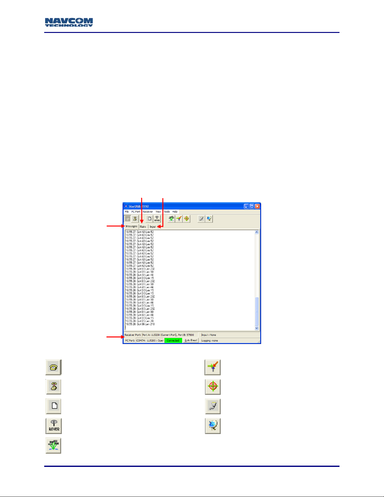
StarUtil-2110 GUI
Messages Tab
(NCT Binary
Messages)
Naks Tab Input Tab
Status Bar
Figure 1: StarUtil-2110 Window
Configure PC COM Port (see Figure 2) View B1 Solution (see Figure 28)
Close PC COM Port View B1 Solution Plot (see Figure 29)
Configure Data Logging (see Figure 38) Configure Receiver Ports (see Figure 4)
Configure Receiver Rover / Navigation &
Tracking Settings (see Figure 8)
View Satellite Status - Message 0x86
(see Figure 26)
Configure Vertical Antenna Bias
(see Figure 12)
1-11
Page 14

StarUtil-2110 User Guide – Rev. B
StarUtil-2110 Main Functions
Configure Rover
Configure the navigation mode, navigation rate and other operational options, such as elevation
mask and 2D/3D solution mode, for the rover. Refer to Chapter 3 Configure Rover
Setup Message Output Lists
StarUtil-2110 provides the user with two windows to schedule and configure messages for
output according to application requirements:
9 NCT Binary Messages Window (see Figure 18)
9 NMEA Messages Window (see Figure 33)
.
The SF-2110 Technical Reference Manual (TRM) details all NCT binary
messages that can be output from the receiver.
View Message Output
9 View Menu: provides access to output of common NCT Binary Messages (see Figure 24)
9 NMEA Viewer: view output of scheduled NMEA Messages (see Figure 39)
Log Message Output
9 Log Data to File Window: log the data from scheduled NCT Binary Messages continuously
in a single file or in 24-hour data file splits (see Figure 38)
9 NMEA Viewer: log the data from scheduled NMEA Messages (see Figure 40)
StarFire Operation
Load or cancel the license for the StarFire subscription service. StarUtil-2110 also provides
functions and data pertinent only to StarFire enabled receivers. Refer to Chapter 6 StarFire
Operation.
Load Software
Load purchased software options and/or free software updates to the SF-2110 receiver. Refer
to Chapter 7 Load Software
.
Configuration Reset
Select Receiver > Commands > Configuration Reset from the menu bar to reset the SF-2110
receiver to factory default settings. This command does not reset the position, time, almanac,
and ephemeris, but resets all other user settings to the factory default.
1-12
Page 15
StarUtil-2110 User Guide – Rev. B
Chapter 2 ............................................................Establish Communications
This chapter provides instructions to:
9 Establish communications between a PC running StarUtil-2110 and the SF-2110 GPS
receiver
9 Configure communications for data cable or Bluetooth.
9 Configure the baud rate of the receiver ports
9 Configure the number of antennas in use (depends on the SF-2110 model)
9 Configure Port B for an auxiliary device
Establish Communications
Initial configuration of Bluetooth does not require a data cable. Bluetooth
configuration instructions are in the section below, Establish Bluetooth
Communications.
1. Connect the PC and the SF-2110 GPS receiver. Use the supplied positronic 9-Pin to DB9S
data cable (P/N 94-310260-3006LF).
Refer to the SF-2110 User Guide for a list of the equipment supplied with the SF-2110
GPS receiver.
2. Run StarUtil-2110 on the PC.
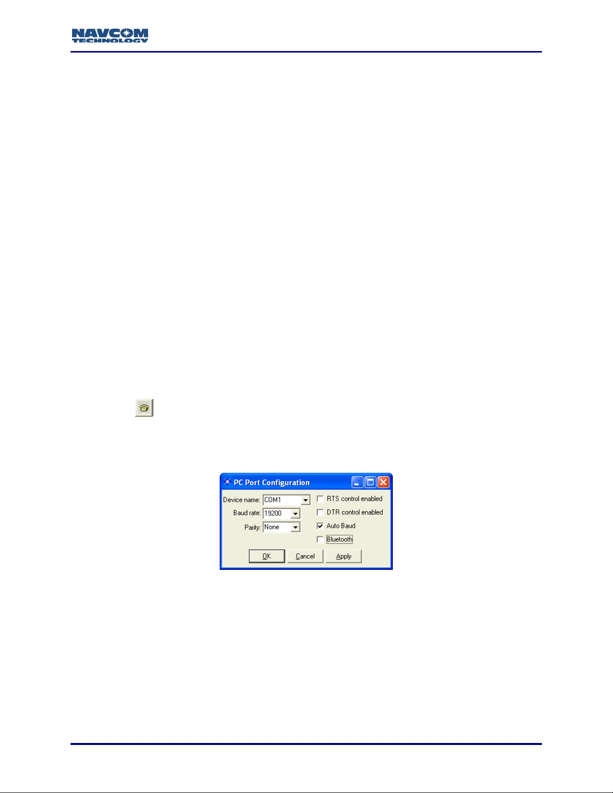
3. Click the
SF-2110 GPS receiver. The PC Port Configuration window opens (see Figure 2).
icon on the toolbar to establish communications between the PC and the
To open the window from the menu bar, select PC Port > Configure PC COM
Port.
Figure 2: PC Port Configuration Window
4. In the Device name drop-down list, select the PC COM port connected to the SF-2110 GPS
receiver.
5. Accept the default option, Auto Baud, or uncheck the Auto Baud box and select a baud rate
from the drop-down list if the current receiver settings are known.
Auto Baud automatically detects the baud rate. If the user manually selects a
baud rate that does not match the current receiver settings, the connection will
fail. To change the baud rate, refer to the section below, Configure Baud Rate of
Receiver Ports.
2-13
Page 16
StarUtil-2110 User Guide – Rev. B
6. Check both options together, RTS control enabled (Request To Send) and DTR control
enabled (Data Terminal Ready), as necessary, to configure the receiver and the computer to
acknowledge readiness before connection is established. This is optional and not required
by the SF-2110.
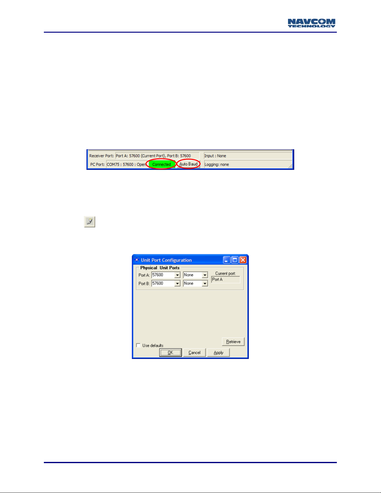
7. Click the OK button. If the connection is successful:
9 NCT Messages scroll down the Messages tab of the StarUtil window.
Refer to Figure 3 for a screen capture of the status bar.
9 The status bar at the bottom of the StarUtil window displays Connected in a green box. It
also provides connection information for both the receiver and PC ports.
9 The Auto Baud button in the status bar becomes active. If StarUtil becomes disconnected,
click the Auto Baud button to re-establish communications.
Figure 3: Status Bar
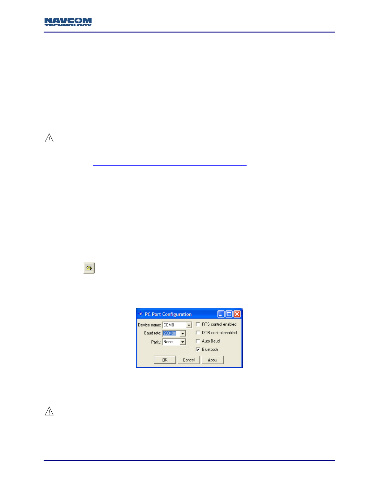
Configure Baud Rate of Receiver Ports
For the Bluetooth interface, go to the next section.
1. Click the
Port Configuration window opens (see Figure 4).
icon on the toolbar to configure the baud rate of the receiver ports. The Unit
To open the window from the menu bar, select Receiver > Setup > Ports.
Figure 4: Unit Port Configuration Window
2. Click the Port A and/or Port B drop-down lists to select a new baud rate, and if necessary,
select the parity.
3. Click the Apply button and then click the Retrieve button to confirm that the receiver accepts
the new setting(s).
• If the receiver does not accept the new baud rate, the baud rate reverts to the previous
value. Click the Naks tab in the StarUtil window to view the error code.
• If the receiver accepts the new baud rate, it is retained in the field.
2-14
Page 17
StarUtil-2110 User Guide – Rev. B
If Auto Baud is not selected in the PC Port Configuration window, the PC port
configuration must be changed to match this new setting (see Figure 2).
4. Click the OK button.
5. Go to the section below, Configure Number of Antenna and Port B for Auxiliary Device.
Establish Bluetooth Communications
1. Setup the software for an internal or external Bluetooth device on the PC. Follow the
instructions in the documentation provided by the manufacturer of the Bluetooth device.
Do not create a secure connection, which requires a password to establish
communications. Passwords are not supported.
Refer to Appendix C Examples of Bluetooth Software Setup for example
instructions.
2. Select a virtual PC COM port for Bluetooth. Remember the COM port number for use in
StarUtil-2110.
3. Place the Bluetooth enabled PC within a maximum of 10 meters (32 feet) from the SF-2110
receiver.
4. Bond (also known as “Pair”) the Bluetooth device on the PC with the SF-2110 receiver.
The GPS receiver is identified as SF2110-[serial number], for example
SF2110-45390. The serial number is on the bottom of the receiver.
5. Run StarUtil-2110 on the PC.
6. Click the
SF-2110 GPS receiver. The PC Port Configuration window opens (see Figure 5).
icon on the toolbar to establish communications between the PC and the
To open the window from the menu bar, select PC Port > Configure PC COM
Port.
Figure 5: PC Port Configuration Window – Bluetooth Settings
7. Click the Bluetooth check box.
8. Uncheck the default option, Auto Baud.
It is important to uncheck Auto Baud. Auto Baud is not supported for the Bluetooth port.
9. In the Device name drop-down list, select the virtual PC COM port for Bluetooth.
10. In the Baud rate drop-down list, select 230400 (the highest Baud rate).
2-15
Page 18
StarUtil-2110 User Guide – Rev. B
11. Do not select RTS control enabled (Request To Send) or DTR control enabled (Data
Terminal Ready).
12. Click the OK button. If the connection is successful:
9 NCT Messages scroll down the Messages tab of the StarUtil window.
9 The status bar at the bottom of the StarUtil window displays Connected in a green box (see
Figure 6). It also provides connection information for both the receiver and PC ports.
The Auto Baud button in the status bar is not supported for Bluetooth.
Figure 6: Status Bar
9 The LED beneath the Bluetooth icon on the front panel of the SF-2110 receiver illuminates
solid blue to indicate successful Bluetooth connectivity (red indicates no Bluetooth
communication).
13. Go to the section below to configure the number of antenna.
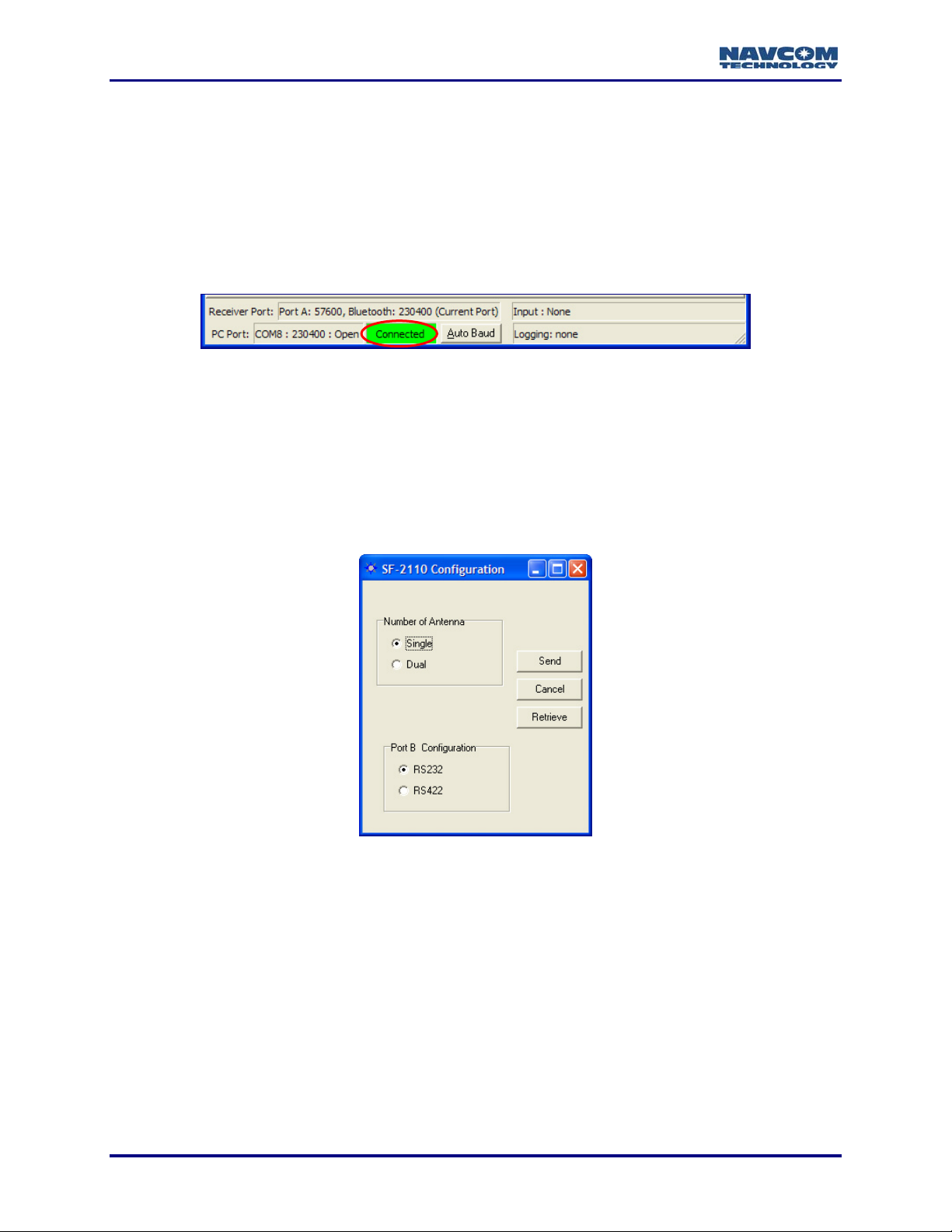
Configure Number of Antenna and Port B for Auxiliary Device
Figure 7: SF-2110 Configuration Window
Select Tools > SF-2110 Configuration from the menu bar. The SF-2110 Configuration window
opens (see Figure 7):
9 Number of Antenna:
• Set to Single (the default) for Model SF-2110M.
• Set to Dual for Model SF-2110R.
9 Port B Configuration: This setting selects the electrical interface option for this port.
2-16
Page 19
StarUtil-2110 User Guide – Rev. B
Chapter 3 ............................................................................Configure Rover
This chapter describes the navigation mode and operational options to configure the rover on
the Rover / Navigation & Tracking Setup window. The options apply to message 0x49 (Solution
Control).
The available navigation modes are:
9 RTCM-104
9 SBAS (WAAS/EGNOS/MSAS/GAGAN)
9 RTG (Access to this mode is available only by purchase of a license for the StarFire
subscription service. Refer to Chapter 6 StarFire Operation
9 Non-differential mode (the default if all the navigation modes above are set to Ignore)
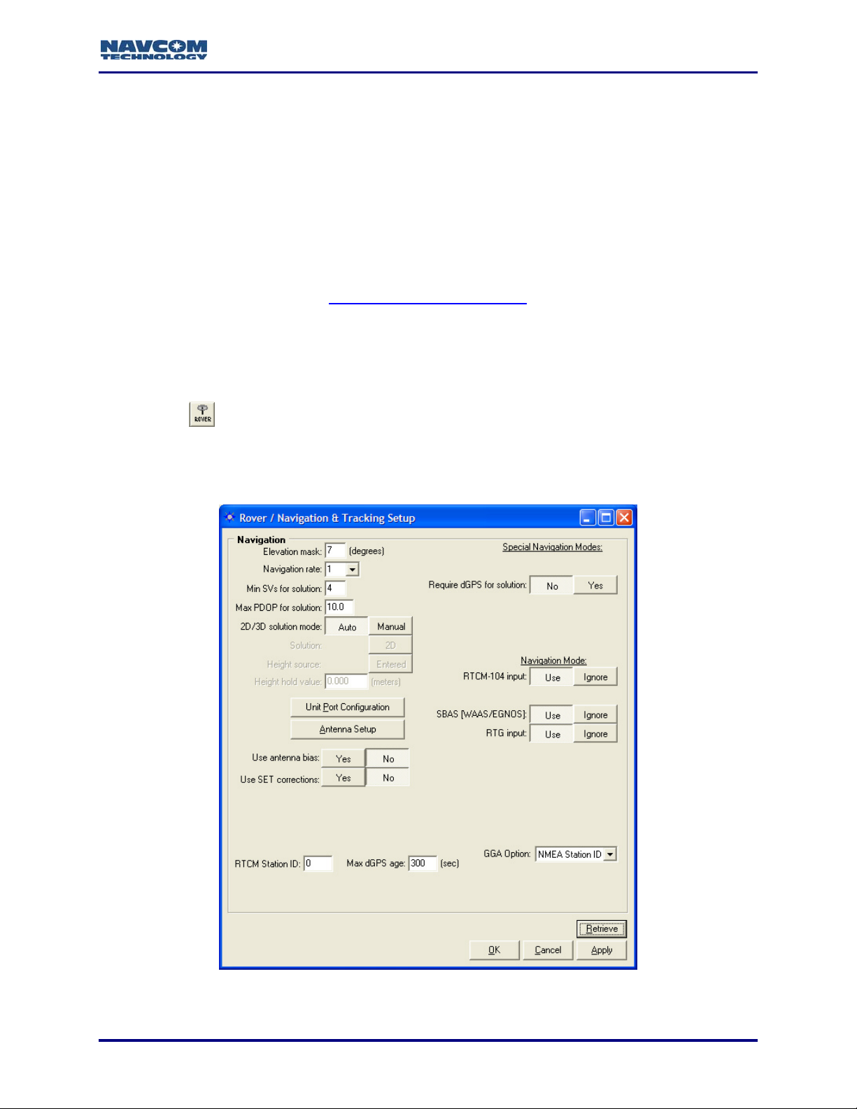
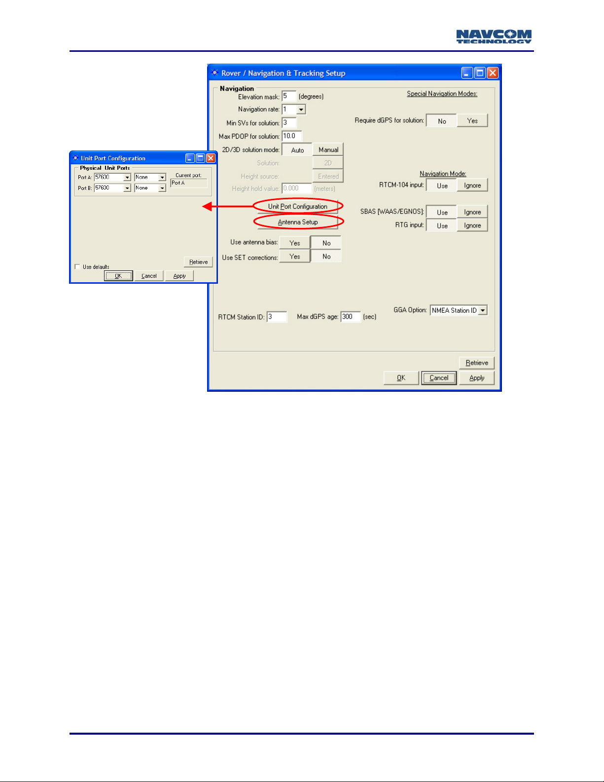
Rover / Navigation & Tracking Setup Window
9 Click the icon on the toolbar to configure the rover. The Rover / Navigation & Tracking
Setup window opens (see Figure 8).
.)
To open the window from the menu bar, select Receiver > Setup > Rover /
Tracking and Navigation.
Figure 8: Rover / Navigation & Tracking Setup Window
3-17
Page 20
StarUtil-2110 User Guide – Rev. B
Refer to Figure 8 for the options in the sections below:
Click the Apply button and then click the Retrieve button to confirm that the
receiver accepts new settings.
Navigation Rate and Other Options
9 Elevation Mask: Enter a value between 0 and 90 degrees to set the elevation angle at which
the receiver will start processing GPS data from satellites.
The default elevation mask is 7 degrees to prevent position jumps due to
frequent satellite re-acquisitions at lower elevation mask angle limits.
9 Navigation Rate: The number of navigation solutions per second. The available rates are:
1Hz (default), 5Hz, and 10Hz. The 5Hz and 10Hz navigation rates are purchased software
options. The upload of a purchased navigation rate changes the setting in the Navigation
rate field automatically to the purchased rate. Refer to Chapter 7 Load Software for
information about the purchase and upload of software options.
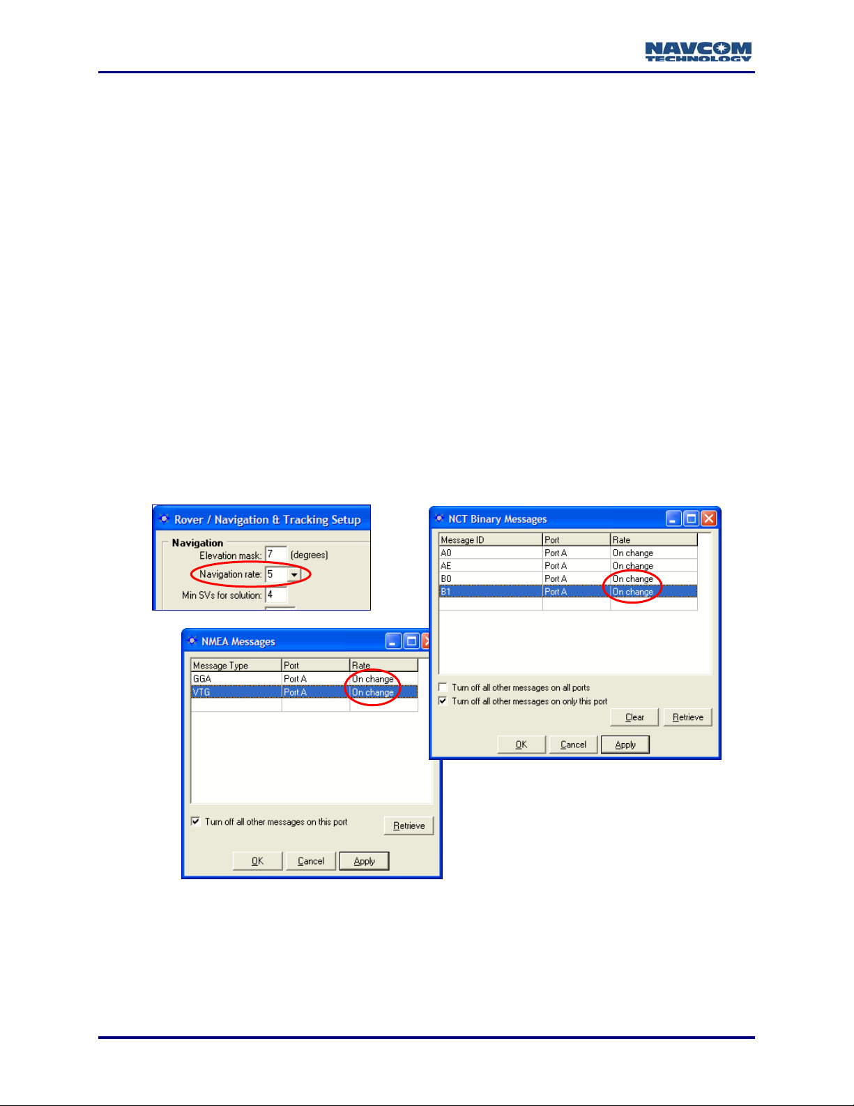
The Navigation Rate setting in the Rover / Navigation & Tracking Setup window
sets the output of the NCT Binary messages B0 and B1 and the NMEA messages
GGA, RMC and VTG provided that those messages are set to On Change in the
NCT Binary Messages window and the NMEA Messages window, respectively
(see Figure 9).
Figure 9: Navigation Rate
When a message is set to On Change, the data is output each time new data is
available as determined by the Navigation Rate setting. For example, if a position
is steadfast at N 33
the Navigation Rate is 5Hz, a 0xb1 solution is output 1 time because the position
3-18
º
50’20.18592” W 118º 20’35.21218” for three seconds and
Page 21
StarUtil-2110 User Guide – Rev. B
didn’t change. If any element of the position changes continuously during the
three second period then a 0xb1 solution is output 15 times.
9 Min SVs for Solution: Accept the default of 4 satellites, or enter a higher number. Four
satellites are the minimum SVs required for a 3D navigation solution, plus an acceptable
PDOP.
9 Max PDOP for Solution: The maximum PDOP value at which the receiver will compute
positions is 25.5. Enter the highest PDOP value according to application requirements. An
applied value above 25.5 reverts to the default of 10.0.
The default setting for Max PDOP is 10. The quality of GPS data is dependent on
the geometry between the receiver and satellites; this includes the number of
satellites that can be "seen" by the receiver and the angle between the receiver
and satellites as a constellation seen by the receiver. A satellite near the horizon
usually provides a lower quality signal because of greater atmospheric
interference and the increased likelihood of the signal reflecting from surface
features; this is known as "multipath" error. The effect of geometry on GPS
quality is measured by PDOP (position dilution of precision). PDOP is the overall
measure of the precision obtainable with a given satellite geometry. For example,
a PDOP of 4 or less yields excellent precision, a PDOP between 5 and 7 is
acceptable and a PDOP of 7 or more is considered poor.
9 2D/3D Solution Mode: Click the Auto or Manual button to determine how height will be
applied to a 2D navigation solution.
• Auto: Sets the receiver to automatically transition between 3D (4 satellite) and 2D (3
satellite) navigation. This can also be determined by DOP values, even if 5 satellites are
available. In 2D navigation, the last valid computed height measurement is used.
• Manual: Enter the Height hold
value to set the receiver to 2D (3
satellite) navigation with the
Height hold value used for the
height measurement. The
receiver must compute an initial
3D navigation solution before it
transitions to 2D navigation. After
2D navigation is established, the
receiver will not transition back to
3D navigation.
Click the icon in the toolbar
to view the current navigation
solution and other parameters of
message 0xB1. The 3D nav field
indicates if 3D navigation is
computed (see Figure 10).
Figure 10: B1 – Solution, 3D nav Field
3-19
Page 22
StarUtil-2110 User Guide – Rev. B
Figure 11: Rover / Navigation & Tracking Setup Window
9 Unit Port Configuration Button: Click this button to configure the baud rate of the receiver
ports. The Unit Port Configuration window opens (see Figure 11). Refer to the section
above, Configure Baud Rate of Receiver Ports, for more information.
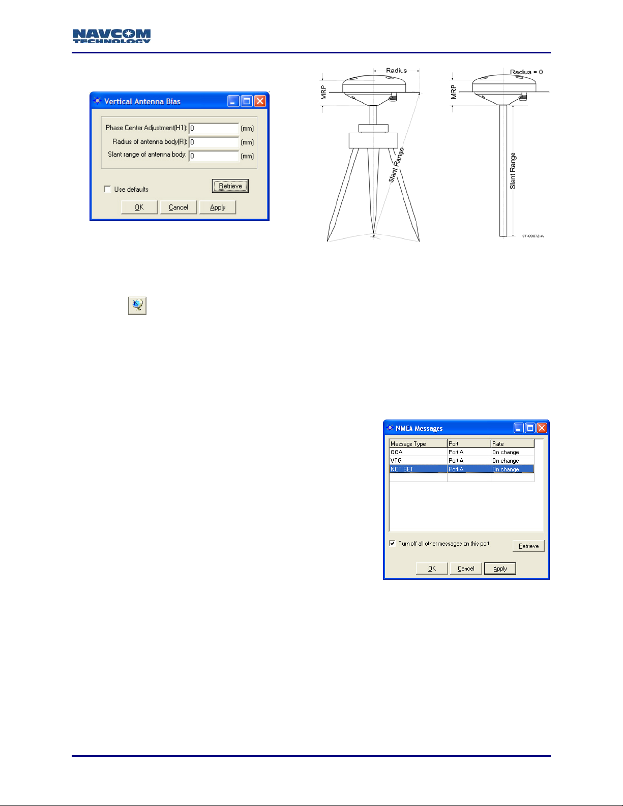
9 Antenna Setup Button: Click this button to set the appropriate bias adjustment values for the
antenna model in use (optional). The Vertical Antenna Bias window opens (see Figure 12):
• Phase Center Adjustment (H1): The offset in millimeters from the physical center of the
antenna (the element) to the Mechanical Reference Plane (MRP). The MRP is at the
bottom of the BSW antenna mount. The range limits are -128 to 127.
• Radius of Antenna Body (R): The measurement in millimeters from the physical center of
the antenna to the edge of the antenna. For a pole, enter 0. For a tripod, the range limits
are -32768 to 32767.
• Slant Range of Antenna Body: For a pole, the vertical measurement in millimeters from
the Mechanical Reference Plane (MRP) to the control point. For a tripod, the
measurement in millimeters from the edge of the antenna to the control point. The range
limits are -32768 to 32767.
3-20
Page 23
StarUtil-2110 User Guide – Rev. B
Figure 12: Vertical Antenna Bias
To access the Vertical Antenna Bias window from the main StarUtil window, click
the
Refer to Figure 11 for the options below.
icon or select Receiver > Setup > Vertical Antenna Bias.
9 Use Antenna Bias: Click the Yes or No button to apply the values set in the Vertical Antenna
Bias window to measurements.
9 Use SET Corrections: Click the Yes or No button to apply Solid Earth Tide (SET) corrections
to measurements.
Requirements for output of SET corrections:
• Message 0x49, W6 B6 set to Apply Correction
• NCT SET scheduled for output in the NMEA
Messages window (see Figure 13)
• A license for the StarFire subscription service. The
option, RTG input, must be set to Use on the Rover /
Tracking & Navigation Setup window.
• Valid Navigation
• Valid SET correctors (A minimum of 1 run of the SET
algorithm. These are an integral part of StarFire
corrections.)
Figure 13: NCT SET
If the criteria above are met, the receiver applies the SET corrections to the position
solution. The B1 Solution tab displays SET North, East, and Up corrections in millimeters
(see Figure 10).
SET refers to Solid Earth Tides. Positions with SET provide better vertical
(primarily) and horizontal positioning accuracy, to account for gravitational effects
placed on terrain from celestial bodies (i.e. the Sun, Moon, etc.).
The SET message output via the NMEA port is a NavCom proprietary NMEA type
message. It conforms to the header, checksum, and electrical characteristics of a
standard NMEA string, but is not recognized by the NMEA governing body as an
3-21
Page 24
StarUtil-2110 User Guide – Rev. B
officially sanctioned message. Refer to Appendix A, Table 4 for a detailed description of
the NMEA Type message structure.
9 RTCM Station ID: The default 0
configures the receiver to accept
corrections from any RTCM Station.
Enter a specific RTCM Station ID to
accept corrections only from that RTCM
Station.
9 Max dGPS Age: Enter the maximum
amount of time in seconds the received
correction will be used in case of an
outage or drop in the reception of
corrections. The time must be within the
max dGPS age limit, which is 1200
seconds. The default is 300 seconds.
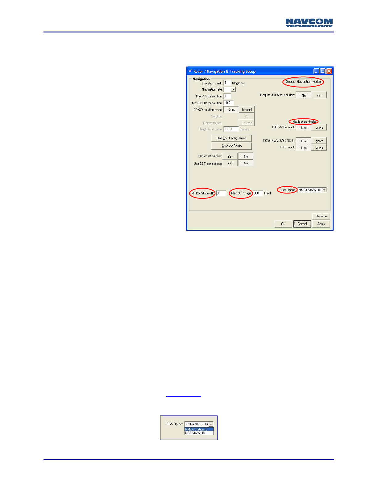
Special Navigation Modes
9 Require dGPS for Solution: The default is
No which indicates that all computed
position solutions are output whether
differentially corrected or not. Click the
Yes button to require only dGPS for
solution.
Figure 14: Rover / Navigation & Tracking Setup Window
Navigation Modes
9 RTCM-104 Input, SBAS [WAAS/EGNOS/MSAS/GAGAN], and RTG Input: The default for all
the navigation modes is Use.
• Access to RTG input is available only by purchase of a license for the StarFire
subscription service. Refer to Chapter 6 StarFire Operation.
• Click the Ignore button to disable a navigation mode.
• Click the Ignore button for all the navigation modes to operate in non-differential mode.
GGA Option
9 GGA Option: Determine how a GGA message is output:
• NMEA Station ID: Accept this default option to output a GGA message that strictly
conforms to the NMEA Standard v3.01.
• NCT Station ID: Select this option to populate the Differential Reference Station ID field
with values that indicate which StarFire satellite is being tracked (1st digit) and the
navigation mode (2nd digit). See Appendix B
for the NCT Station ID matrix.
The differential reference station is field 14 in the NMEA GGA message.
3-22
Figure 15: GGA Option
Page 25

StarUtil-2110 User Guide – Rev. B
WAAS Prn Selection
The WAAS Prn Selection window enables the user to manually configure the receiver to receive
corrections from one or two L1 SBAS satellites.
The WAAS Prn Selection window is functional for all SBAS systems that comply
with the RTCA/DO-229D standard: WAAS, EGNOS, MSAS, and GAGAN. Refer
to Related Standards in the fore-matter.
Figure 16: WAAS Prn Selection Window
9 Select Receiver > Setup > Select WAAS Prns. The WAAS Prn Selection window opens (see
Figure 16).
9 Enter one or two L1 SBAS satellite Prns.
9 Determine the mode of the Prns:
• Manual Mode: Always use the entered prns.
• Auto Mode: Use the prns if the receiver doesn’t have a valid position fix. The receiver will
update the SBAS prns to use after it has a valid position.
3-23
Page 26

StarUtil-2110 User Guide – Rev. B
This page is left blank intentionally
3-24
Page 27

StarUtil-2110 User Guide – Rev. B
Chapter 4 .........................................................Setup Message Output Lists
This chapter provides guidance to schedule and configure messages for output in the:
9 NCT Binary Messages Window
9 NMEA Messages Window
In addition, this chapter describes the use of the View menu to access the output data of
common NCT Binary Messages, and provides details on the output for messages 86-Channel
Status, A0-Alerts, B0-Raw Measurements, B1-Solution Plot, B1-Solution, and EC-5C Delta
Time.
Refer to the SF-2110 Technical Reference Manual for details of the control and
output data message formats utilized by the SF-2110 receiver.
Refer to Chapter 5 Log Output Data for instructions to log NCT Binary and NMEA
Messages.
NCT Binary Messages
NCT Binary Message Output List: Add, Configure, or Delete Messages
Open Message Output List
Figure 17: Messages Menu
9 Select Receiver > Messages > NCT output from the menu bar (see Figure 17). The NCT
Binary Messages window opens with the current message output list (see Figure 18).
Figure 18: NCT Binary Message Output List
4-25
Page 28

StarUtil-2110 User Guide – Rev. B
After making any settings in the sections below, click the Apply button and then
click the Retrieve button to confirm that the receiver accepts the settings.
Add Messages
9 Right-click in a blank Message ID cell. A menu opens with a list of commonly used
messages (see Figure 19).
9 Click on a message in the menu to add it to the list or click Other to type in the hex ID of a
message. Other message IDs are defined in the SF-2110 Technical Reference Manual
(TRM).
The default port of a new message is Port A, and the default rate is On Change.
Refer to the next section to configure the port and/or rate if necessary.
Figure 19: Message ID Menu
Configure Messages
9 Port: Right-click on the Port cell to select Port A, Port B, or Bluetooth based on where the
message is needed (see Figure 20).
Figure 20: Port Menu
4-26
Page 29

StarUtil-2110 User Guide – Rev. B
To facilitate a possible change in port connection, messages may be configured
for both ports, as shown in the example in Figure 21.
Figure 21: Messages Configured for Both Ports A and B
9 Rate: Use of the default rate value (On Change) is recommended for messages with a
consistent periodic rate. The term On Change indicates that the receiver will output the
specified message each time new data is available. Refer to the description of the
Navigation Rate option
information.
on the Rover / Navigation & Tracking Setup window for more
For a message that is not frequently updated, schedule a rate other than On
Change. For example, message AE, scheduled at On Change, outputs only
when new software is uploaded to the receiver. In the example in Figure 22, the
rate is Every 600 seconds (the default).
Figure 22: Example of a Specific Period
Right-click on the Rate cell to open the menu to schedule the frequency of output for a
message (see Figure 23).
4-27
Page 30

StarUtil-2110 User Guide – Rev. B
Figure 23: Rate Menu
• Specific Rate: Select 1Hz, 5Hz, or 10Hz. NCT binary messages do not output at 5Hz or
10Hz unless the user purchases a license for those navigation rates.
• Specific Period: Enter a value in seconds in the Rate cell.
• Other:
o All SVs: Not Applicable
o *On Trigger: Select this option to schedule the SF-2110 to accept an event input
pulse to synchronize external incidents requiring precise GPS time tagging, such as
aerial photography. For example, the action of a camera’s aperture creates an input
pulse to the Event port. The SF-2110 outputs position and time information relative to
each photograph taken. Refer to Chapter 8, 1PPS/Events
o Special Value: Not Applicable
Delete Messages
To delete one or more messages:
9 Right-click on a message. A menu opens. Select Delete at the bottom of the menu to delete
the message.
Or
9 Click on a message to highlight it. Press the Delete key on the keyboard.
9 Press the Clear button to clear all messages from the list so that new messages may be
easily added.
for more information.
This action is not complete until the Apply button or OK button is clicked. Failure
to send the deleted list causes the previous list to be retained.
View NCT Binary Message Output Data
The View menu provides access to the output data of common NCT Binary Messages (see
Figure 24).
Refer to the sections below for details on the output data for messages
86-Channel Status, A0-Alerts, B0-Raw Measurements, B1-Solution Plot,
B1-Solution, and EC-5C Delta Time. Refer to Figure 57 for details on message
30-Software Options. Refer to the section, View Menu – StarFire Information, for
details on messages pertaining to the StarFire subscription service.
* Consult Release Notes on the NavCom web site for availability.
4-28
Page 31

StarUtil-2110 User Guide – Rev. B
The A1 – System Profile window is for factory use only.
9 Select View from the menu bar to open a menu of message outputs to view.
Figure 24: View Menu
9 Click a message on the View menu. A tab for the message opens (see Figure 25).
Drag the tab to the desktop to view the message output in a window. Drag the
window back to StarUtil to view again as a tab.
Some messages, such as 86, B0, and B1, must be scheduled for output to view
data. For other messages, such as 30 and AE, click the Retrieve button on the
tab to view data.
4-29
Page 32

StarUtil-2110 User Guide – Rev. B
Message Tabs
Figure 25: Message Tabs
9 In addition to the View menu, click the icons to view:
Channel (Satellite) Status
B1 Solution
B1 Solution Plot
4-30
Page 33

StarUtil-2110 User Guide – Rev. B
86 Channel Status – E1 Satellite Failure
The 86-Channel Status tab is a powerful tool that provides instantaneous diagnosis of signal
quality and performance (see Figure 26). The SF-2110 receiver has 16 channels.
This message must be scheduled for output to view data. If not scheduled, select
Receiver > Messages > NCT output from the menu bar. The NCT Binary
Messages window opens. Add this message to the output list (see Figure 19).
7-16
17
Figure 26: 86 – Channel Status
1. Week: GPS Week number (Refer to the SF-2110 Technical Reference Manual)
2. Time: GPS Seconds into the week (Refer to the SF-2110 Technical Reference Manual)
3. SVs Visible: Satellite Vehicles Visible. The number of GPS satellites visible according to the
current almanac stored in NVRam based on the user-defined elevation mask and current
position.
4. PDOP: Position Dilution of Precision. During periods of optimal performance, PDOP is
typically between 2 and 5, based on the satellites used.
5. Tracked: The number of GPS satellites currently tracked by the receiver.
6. Used: Of the number being tracked, the actual number of GPS satellites currently being used
in the navigation filters to determine position, velocity, and time.
7. Ch: The channel number of the receiver.
4-31
Page 34

StarUtil-2110 User Guide – Rev. B
8. SV: The GPS or WAAS satellite number assigned to that particular channel. The valid GPS
PRN range is 1-32. The valid WAAS PRN range is 120-138.
9. State: The NCT proprietary satellite tracking value assigned to each satellite tracked that
indicates the type of tracking mode the satellite is in. This value ranges between 0 and 7, with
7 being optimal for GPS performance. Lower values indicate that the satellite is not available
for use. This may be due to lack of dGPS corrections, cycle slips, acquisition process, etc.
10. Elevation: The vertical angle of the satellite off the horizon ranging from 0 degrees to a
zenith of 90 degrees.
11. Azimuth: The horizontal angle of the satellite relative to the receiver position in reference to
North ranging from 0 (360) to 359 degrees.
12. CA: The L1 signal-to-noise value, which will vary depending on satellite elevation and any
obstructions between the satellites and the receiver. Optimal performance range for L1 C/N0
is 46dB to 52dB, although higher and lower values can be noted. A value > 50 is typical of a
satellite with 50º elevation or higher and a clear view of the sky.
13. P2: Not applicable to the SF-2110.
14. IODC: Issue of Data Clock. Indicates the issue number of the data as provided from the
GPS satellite in accordance with ICD-200C.
15. dGPS Age: The age of the current aided navigation correction. This value changes
depending on the correction source, and the correction interval.
16. Status: Not applicable to SF-2110
17. Last: Shows the MM:DD:YYYY and HH:MM:SS of the last 0x86 message update.
A0 – Alerts
The A0-Alerts tab displays alerts in real time only. No alerts are archived.
4-32
Page 35

StarUtil-2110 User Guide – Rev. B
3
0
B0 – Raw Measurements
This message must be scheduled for output to view data. If not scheduled, select
Receiver > Messages > NCT output from the menu bar. The NCT Binary
Messages window opens. Add this message to the output list (see Figure 19).
4 - 9
1
Figure 27: B0 – Raw Measurements
1. Week: GPS Week number (Refer to the SF-2110 Technical Reference Manual)
2. Time: GPS Seconds into the week (Refer to the SF-2110 Technical Reference Manual)
3. SV Count: The number of GPS satellites currently tracked by the receiver.
4. Ch: The channel number of the receiver.
5. SV: The GPS or WAAS satellite number assigned to that particular channel. The valid GPS
PRN range is 1-32. The valid WAAS PRN range is 120-138.
6. C/NO: Carrier-to-noise ratio. The signal strength indictor.
7. CA: Coarse Acquisition code. The number of meters (range measurement) to the satellite.
8. L1: The number of carrier cycles between the satellite and the receiver.
9. Doppler: The fractional equivalent of the Doppler frequency. (Refer to the SF-2110 Technical
Reference Manual. The Doppler values are calculated from Wn4 in the 0xB0 message.)
10. Last: Shows the MM:DD:YYYY and HH:MM:SS of the last 0xB0 message update.
4-33
Page 36

StarUtil-2110 User Guide – Rev. B
6
8
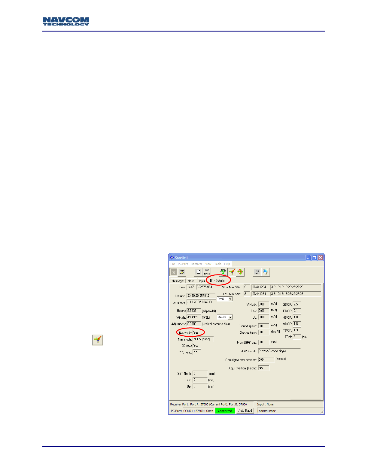
B1 – Solution
This message must be scheduled for output to view data. If not scheduled, select
Receiver > Messages > NCT output from the menu bar. The NCT Binary
Messages window opens. Add this message to the output list (see Figure 19).
2
14
12
10
11
12
13
Figure 28: B1 – Solution
1. Time: GPS Week number and GPS Seconds into the week (Refer to the SF-2110 Technical
Reference Manual)
2. Latitude/Longitude: Select DMS, Deg, DM, or Rad from the drop-down list.
3. Height/Altitude: Select Meters or Feet. The unit of measurement applies to Height, Altitude,
and Vertical Antenna Bias.
4. Vertical Antenna Bias Adjustment: Bias adjustment value for the antenna model in use.
Click the
icon to set the bias in the Vertical Antenna Bias window (see Figure 12).
5. Nav: Various indications of navigation. If disconnected from the receiver, Nav mode toggles
to Failure code. If the value for 3D nav is No, the receiver is in 2D navigation. *PPS valid
indicates whether or not 1PPS (One Pulse Per Second) output is valid. Refer to Chapter 8
1PPS/Events for more information.
6. SET: Solid Earth Tides. Positions with SET provide better vertical (primarily) and horizontal
positioning accuracy, to account for gravitational effects placed on terrain from celestial
bodies (i.e. the Sun, Moon, etc.). Refer to the description of the Use SET Corrections option
on the Rover / Navigation & Tracking Setup window.
* Consult Release Notes on the NavCom web site for availability.
4-34
Page 37

StarUtil-2110 User Guide – Rev. B
7. Slow and Fast Nav SVs:
Number of SVs Tracked
Hex of SV IDs IDs of SVs Tracked
Hex Binary IDs of SVs Tracked
0D441284 00001101010001000001001010000100 00001101010001000001001010000100
1
271023001900001301080000300
2802523001900001301080000300
8. Velocity: The vectors for satellite velocity.
9. Ground Speed and Track: The speed over ground and direction of travel (true, not
magnetic).
10. Max dGPS age: The maximum amount of time in seconds for all received corrections in the
current position record. Click the
icon on the toolbar to set the Max dGPS age on the
Rover / Navigation & Tracking Setup window (see Figure 8). The displayed time must be
within the max dGPS age limit, which is 1200 seconds. The default max dGPS age limit is
300 seconds.
11. dGPS mode: The current dGPS navigation mode. The possible modes are:
0: Non-differential
1: RTCM type 1 and 9 code
2: WAAS code single
6: RTG single
12. FOM: The DOP Figure Of Merit is the estimated uncertainty in the navigation solution. FOM
is the same as the One sigma error estimate. (Refer to the SF-2110 Technical Reference
Manual)
13. Adjust vertical (height): Indicates whether or not there is a bias adjustment value for the
antenna model in use (see Item 4
above).
14. DOP: Dilution of Precision. A class of measures of the magnitude of error in GPS position
fixes due to the orientation of the GPS satellites with respect to the GPS receiver. There are
several DOPs to measure different components of the error: GDOP (Position and Time),
PDOP (Dimensional Position), HDOP (Horizontal Position), VDOP (Vertical Position), and
TDOP. The maximum PDOP value is 25.5.
4-35
Page 38

StarUtil-2110 User Guide – Rev. B
6
B1 – Solution Plot
The B1 message must be scheduled for output for the solution plot to be active. If
the B1 message is not scheduled, select Receiver > Messages > NCT output
from the menu bar. The NCT Binary Messages window opens. Add message B1
to the output list (see Figure 19).
Figure 29: B1 – Solution Plot
1. Merit: The Figure Of Merit is the estimated uncertainty in the navigation solution.
2. SVs: The current number of satellite vehicles being tracked.
3. Nav Mode: The current navigation mode (see B1 – Solution, Item 11
4. Zoom in/ Zoom Out
5. Set scale: Enter a scale value in meters and click the Set scale button
plot is scaled, previously displayed plot points are erased.
6. Set origin: Click to set the origin source. The B1 – Plot Origin window opens (refer to the
instructions below).
7. Erase: Clear the plot.
8. Snapshot to paste buffer
9. Last: Shows the MM:DD:YYYY and HH:MM:SS of the last update of the plot.
above).
. Each time the
4-36
Page 39

Set the Origin Source
StarUtil-2110 User Guide – Rev. B
9 Click the
icon to open the B1 – Plot Origin window (see Figure 30).
Figure 30: B1 – Plot Origin Window
9 Set the origin source from the:
• First Point Received: (default) Select DMS, Deg, DM, or Rad from the drop-down list for
Latitude and Longitude. Select Meters or Feet from the drop-down list for Altitude. Click
the Apply button. The first point received is plotted in the center of the crosshairs.
• Known Latitude and Longitude: Click the Entered values button. Type in the known
Latitude and Longitude. Select DMS, Deg, DM, or Rad from the drop-down list for
Latitude and Longitude. Select Meters or Feet from the drop-down list for Ellipsoidal
Height. Click the Apply button. The origin is plotted from the entered values.
4-37
Page 40

StarUtil-2110 User Guide – Rev. B
EC – 5C Delta Time
The EC-5C Delta Time tab provides the last received dGPS corrections on the data port
receiving port corrections (not StarFire corrections).
This message must be scheduled for output to view data. If not scheduled, select
Receiver > Messages > NCT output from the menu bar. The NCT Binary
Messages window opens. Add this message to the output list (see Figure 19).
1
Figure 31: EC – 5C Delta Time
1. Site ID: The Reference Station ID.
2. l1 Prns: The number of satellites from which corrections are available.
3. RTCM1,9_dt: The Delta Time in seconds for RCTM correction types 1 and 9.
4. RTCM3_dt: The Delta Time in seconds for RCTM correction type 3.
5. Last: Shows the MM:DD:YYYY and HH:MM:SS of the last EC-5C Delta Time message
update.
4-38
Page 41

StarUtil-2110 User Guide – Rev. B
NMEA Messages
This section provides steps to add NMEA messages to an output list, and to configure and
delete messages from the list. The receiver has the ability to output industry standard
NMEA-0183 data strings, and one NCT Proprietary NMEA-0183 type string.
Refer to the section, View and Log Data – NMEA Messages, in Chapter 5 for
instructions to view and log NMEA message output data.
NMEA Message Output List: Add, Configure, or Delete Messages
Open Message Output List
Figure 32: Messages Menu
9 Select Receiver > Messages > NMEA output from the menu bar (see Figure 32). The NMEA
Messages window opens with the current message output list (see Figure 33).
Figure 33: NMEA Message Output List
Click the Apply button and then click the Retrieve button to confirm that the
receiver accepts new settings.
Add Messages
9 Right-click in a blank Message Type cell. A menu opens with a list of messages (see
Figure 34).
9 Click on a message in the menu to add it to the list.
The default port of a new message is Port A, and the default rate is On Change.
Refer to the next section to configure the port and/or rate if necessary.
4-39
Page 42

StarUtil-2110 User Guide – Rev. B
Figure 34: Message Type Menu
Configure Messages
9 Port: Right-click on the Port cell to select Port A, Port B, or Bluetooth, depending on the
current port connection (see Figure 35).
Figure 35: Port Menu
9 Rate: Use of the default rate value (On Change) is recommended for all NMEA messages.
The term On Change indicates that the receiver will output the specified message each time
new data is available.
The NMEA messages GGA, RMC, and VTG match the output of the navigation
rate when scheduled as “On Change”. These messages may be output at rates
higher than 1Hz. The 5Hz and 10Hz navigation rates are purchased software
options. Refer to the description of the Navigation Rate option
Navigation & Tracking Setup window for more information.
If desired, right-click on the Rate cell to open the menu to schedule the frequency of output
for a message (see Figure 36).
• Specific Period: Enter a value in seconds in the Rate cell.
• Other:
o All SVs: Not Applicable
4-40
on the Rover /
Page 43

StarUtil-2110 User Guide – Rev. B
o *On Trigger: Select this option to schedule the SF-2110 to accept an event input
pulse to synchronize external incidents requiring precise GPS time tagging, such as
aerial photography. For example, the action of a camera’s aperture creates an input
pulse to the Event port. The SF-2110 outputs position and time information relative to
each photograph taken. Refer to Chapter 8, 1PPS/Events
o Special Value: Not Applicable
Figure 36: Rate Menu
for more information.
Delete Messages
9 Right-click on a message. A menu opens. Select Delete at the bottom of the menu to delete
the message.
9 Click on a message to highlight it. Press the Delete key on the keyboard.
This action is not complete until the Apply button or OK button is clicked. Failure
to send the deleted list causes the previous list to be retained.
NMEA GGA Station ID Field 14
The GGA Option on the Rover / Navigation & Tracking Setup window determines how a GGA
message is output (see Figure 37):
• NMEA Station ID: Accept this default option to output a GGA message that strictly
conforms to the NMEA Standard v3.01.
• NCT Station ID: Select this option to populate the Differential Reference Station ID field
with values that indicate which StarFire satellite is being tracked (1st digit) and the
navigation mode (2nd digit). See Appendix B
for the NCT Station ID matrix.
The differential reference station is field 14 in the NMEA GGA message.
Click the icon on the toolbar to open the Rover / Navigation & Tracking Setup
window.
Figure 37: GGA Option
4-41
Page 44

StarUtil-2110 User Guide – Rev. B
This page is left blank intentionally
4-42
Page 45

StarUtil-2110 User Guide – Rev. B
Chapter 5 ............................................................................Log Output Data
This chapter provides instructions to log output data for NCT Binary Messages and NMEA
Messages. Log data from either of the physical ports. This data can be used in a number of
industry standard GPS data analysis programs either in NCT Binary format, after conversion to
RINEX format, or by using the NMEA output.
Log Data – NCT Binary Messages
The data from NCT Binary Messages scheduled for output may be:
9 Logged continuously in a single file
9 Logged in 24-hour data file splits
Almanac & Ephemeris data currently in the receiver’s NVRam is automatically
downloaded to the data file when logging is initiated, regardless of whether the
Almanac & Ephemeris messages are scheduled for output in the NCT Binary
Messages window.
9 Click the
Figure 38). The Current Status area of the window indicates: if logging is enabled, if the
scheduler [24-hour splits] is enabled, and the path to the log file.
icon on the toolbar to log data to a file. The data logging window opens (see
To open the data logging window from the menu bar, select File > Log Data to File.
Figure 38: NCT Binary Messages Data Logging Window
5-43
Page 46

StarUtil-2110 User Guide – Rev. B
Log Data in Single File
9 Rename the NCT.dat file, if desired.
9 Click the
button to select a directory in which to save the file.
StarUtil creates a folder under the selected directory, named in the yymmdd
format. For example, the directory path d:\NavComWorking\Data would become
d:\NavComWorking\Data\yymmdd.
9 Click the Start Log button to begin logging the output data. Click the Stop Log button to stop
logging.
Log Data in 24-hour File Splits
9 Click the button to select a directory in which to save the data files.
9 Click the Apply button in the Logging Schedule area of the window to start logging in 24-
hour data file splits. Click the Stop button to stop logging.
The file splits restart at 00:00:00 GMT, and create a new folder name at each 24-
hour period.
View and Log Data – NMEA Messages
View Data
9 Select Tools > NMEA Viewer from the menu bar. The viewer opens with data output from
the scheduled NMEA messages (see Figure 39).
Figure 39: NMEA Viewer
If needed, a second instance of StarUtil may be run to view simultaneously NCT
Binary Messages on one port and NMEA Messages on the other. If both NCT
Binary and NMEA data are present on the same port, the data may also be
viewed simultaneously in the NMEA viewer and from the View menu.
5-44
Page 47

Log Data
Refer to Figure 40 for the steps below:
StarUtil-2110 User Guide – Rev. B
9 Click the
button to create a log file. A window opens.
9 Rename the NMEA.log file, if desired, and save it in a folder. The NMEA Viewer window
displays the path.
9 Click the Start button to begin logging the output data. Click the Stop button to stop logging.
Figure 40: NMEA Logging
5-45
Page 48

StarUtil-2110 User Guide – Rev. B
This page is left blank intentionally
5-46
Page 49

StarUtil-2110 User Guide – Rev. B
Chapter 6 ........................................................................ StarFire Operation
This chapter provides:
9 Instructions to load and cancel the license for the StarFire subscription service.
Refer to Chapter 7 Load Software for information about the purchase of software
options for the SF-2110 GPS receiver.
9 Information about the menu options in StarUtil-2110 that are pertinent only to StarFire
enabled receivers:
• StarFire Menu (see Figure 43):
o Provides options to augment StarFire functionality.
• View Menu (see Figure 46):
o Provides access to the NavCom receiver serial number, StarFire license information,
the StarFire software version in use, and StarFire satellite data.
Description of the StarFire Network
The StarFire Network is a global system for the distribution of SBAS corrections giving the user
the ability to measure his position anywhere in the world with exceptional reliability and
unprecedented accuracy of better than 80cm (2.62 ft), (50cm, 1.64 ft in WAAS coverage areas).
Because the SBAS corrections are broadcast via INMARSAT geo-stationary satellites, the user
needs no local reference stations or post-processing to get this exceptional accuracy.
Furthermore, the same accuracy is available virtually anywhere on the earth's surface on land or
sea from 76°N to 76°S latitude, due to the worldwide coverage of these geo-stationary satellites.
How to Access the StarFire Service
StarFire is a subscription service. The user pays a subscription, which licenses the use of the
service for a predetermined period of time.
Subscriptions are available via a NavCom authorized representative, or by contacting NavCom
Sales Department (sales@navcomtech.com).
An authorized subscription provides an encrypted key, which is specific to the serial number of
the NavCom receiver to be authorized. Typically the initial license is preinstalled at the factory,
and the user installs subsequent licenses with StarUtil-2110. The user receives the StarFire
license file via email.
Please provide the NavCom receiver serial number and the serial number on the SF-2110
chassis when requesting a new StarFire license.
To view the NavCom receiver serial number, select View > AE-Version
Information (see Figure 47) or View > D1-LBD License Status (see Figure 49).
6-47
Page 50

StarUtil-2110 User Guide – Rev. B
Load StarFire License
The receiver must be navigating at the time of the license update for the receiver
to accept the license.
9 Save the StarFire license file received via email to the hard drive.
9 Select Tools > StarFire License Input to upload the StarFire license. The LBD License
window opens (see Figure 41).
Figure 41: StarFire License Upload Window
9 Click the
appears in the LBD License window.
9 Click the Update button. A window opens to indicate a successful upload.
9 Click the
Rover / Navigation & Tracking Setup window opens. The navigation mode, RTG input, must
be set to Use (the default) to enable StarFire navigation (see Figure 42).
button to browse to and select the StarFire license file. The path to the file
icon on the toolbar to confirm that the rover is configured for StarFire. The
Figure 42: Rover Configured for StarFire Navigation
To verify an active StarFire license, select View > D1 – LBD License Status. Click
the Retrieve button on the D1 tab. If no license is displayed on the tab, the
receiver will not decode the StarFire signal. If no license is displayed, select
View > D5 – LBD License Cancel History to display cancelled licenses.
6-48
Page 51

StarUtil-2110 User Guide – Rev. B
Cancel StarFire License
The receiver must be navigating at the time of this command for the receiver to
accept the license cancellation.
9 Select Receiver > Commands > Cancel StarFire License. A caution message opens.
9 Click OK on the first caution message and Yes on the second message to cancel the
StarFire license.
9 Refer to the sections below:
• D5 – LBD License Cancel History: the history of the last two StarFire license
cancellations
• DD –
LBD License Cancel Codes: cancel codes to affirm the cancellation of the last two
StarFire licenses before the expiration dates
StarFire Menu Options
The StarFire menu options (see Figure 43), which are described in more detail below, are:
9 Alternate Channel: Select this option to manually force the receiver to use a licensed
StarFire satellite or user-defined satellite in case of poor reception or during routine
maintenance of the StarFire Network.
9 Define Satellite: With direction from NavCom, select this option to add (or delete) one
licensed user-defined StarFire satellite to be available for automatic or manual selection.
The user-defined satellite is a new satellite in the StarFire network or a backup StarFire
satellite.
Figure 43: StarFire Menu
Alternate Channel
Select this option to manually force the receiver to use a licensed StarFire satellite or userdefined satellite in case of poor reception or during routine maintenance of the StarFire
Network. The receiver does not have to use the frequency table to search for the StarFire
signal.
The satellite selection is based on the license type and current GPS position.
6-49
Page 52

StarUtil-2110 User Guide – Rev. B
Figure 44: LBD Alternate Channel Window
9 Select Receiver > Setup > StarFire > Alternate Channel. The LBD Alternate Channel
window opens (see Figure 44).
9 Click the check box to the left of Use Alternate Satellite.
9 Type in a valid satellite ID in the Alternate Satellite ID field:
• An available licensed StarFire satellite. (Table 1 identifies StarFire Satellites by
Network.)
Or
• The user-defined StarFire satellite (if defined).
Table 1: StarFire Satellites
Network Satellite ID Longitude
402 98W PAC-E Laurentides
Net 1
Net 2
609 109E IND-E Perth
525 25E IND-W Burum
358 142W PAC-C Santa Paula
643.5 143.5E PAC-W Auckland
484.5 15.5W AOR-E Southbury
Satellite
Name
Uplink Site
The Satellite IDs may change after September 19, 2008, as replacement
satellites are brought into service for these aging satellites.
9 Click the Apply button and then the Retrieve button:
• If the satellite ID is accepted, it remains in the Alternate Satellite ID field, and the check
box remains checked.
• If the satellite ID is not accepted, the Alternate Satellite ID field displays “0”, and the
check box is blank.
9 Confirm the manual selection of the alternate satellite on either of these tabs:
• Select View > DB – StarFire Satellites. The DB-StarFire Satellites tab opens (see Figure
53). Click the Retrieve button. The Satellite Selection Mode is Manual.
The Satellite Selection Mode identifies the manual selection of the alternate
satellite. The alternate satellite is not highlighted in the list on the tab.
• Select View > D3 – LBD DSP Status. The D3-LBD DSP Status tab opens (see
Figure 51). Click the Retrieve button. Yes is the entry in the field to the left of Use
alternate channel.
6-50
Page 53

StarUtil-2110 User Guide – Rev. B
Define Satellite
With direction from NavCom, select this option to add (or delete) one licensed user-defined
StarFire satellite to be available for automatic or manual selection. The user-defined satellite is
a new satellite in the StarFire network or a backup StarFire satellite.
Only one satellite can be user-defined. A new user-defined satellite overwrites
the previous user-defined satellite.
Figure 45: Define Satellite Window
Enter User-Defined Satellite 9 Select Receiver > Setup > StarFire > Define Satellite. The Define Satellite window opens
(see Figure 45).
9 Click the check box to the left of Enter User-Defined Satellite.
9 With direction from NavCom, enter the Frequency(KHz) and the Satellite ID for the user-
defined satellite.
9 Click the OK button.
9 Confirm that the entry of the user-defined satellite is successful:
• Select View > DB - StarFire Satellites. The DB-StarFire Satellites tab opens (see
Figure 53).
• Click the Retrieve button.
• The new user-defined satellite is listed on row 7 of the tab.
Delete User-Defined Satellite 9 Select Receiver > Setup > StarFire > Define Satellite. The Define Satellite window opens
(see Figure 45).
9 Click the check box to the left of Delete User-Defined Satellite.
9 Click the OK button.
9 Confirm that the user-defined satellite is deleted:
• Select View > DB - StarFire Satellites. The DB-StarFire Satellites tab opens (see
Figure 53).
• Click the Retrieve button.
• Row 7 on the tab is blank if the user-defined satellite is deleted.
6-51
Page 54

StarUtil-2110 User Guide – Rev. B
View Menu – StarFire Information
Figure 46 shows all the messages checked on the View menu that pertain to the StarFire
subscription service. Refer below for descriptions of the message tabs.
Figure 46: View Menu – StarFire Information
StarFire Licensing Terminology
Table 2 lists the StarFire licensing terminology that is used on various tabs.
Table 2: StarFire Licensing Terminology
Terms Description
Precise Indicates that the license type is a StarFire license.
Indicates the license type in regards to valid areas of StarFire operation:
World Wide or Land Only
Calendar Time or
Run-Time (Elapsed Time)
Active or Inactive Indicates the current status of the StarFire license.
• World Wide: Valid globally.
• Land Only: Valid only on land (or near land as defined by NavCom).
Indicates the license type in regards to duration of StarFire operation:
• Calendar Time: The receiver is licensed for a specified duration.
• Run-Time: The receiver is licensed at a per day rate.
Canceled or Expired
6-52
Indicates how the StarFire license was terminated:
• Canceled: Terminated by the user.
• Expired: The end date for the license is reached or all the
run-time days are used.
Page 55

StarUtil-2110 User Guide – Rev. B
AE – Version Information
The AE-Version Information tab provides various version and serial numbers.
9 Click the Retrieve button to view the current output data:
• Digital Card Serial Number: Provide this serial number to NavCom when requesting a
new StarFire license. For further details on the StarFire Signal Network, its capabilities,
terms and conditions visit www.navcomtech.com
sales@navcomtech.com
.
or send an email inquiry to
The D1-LBD License Status tab also displays the serial number (see Figure 49).
Figure 47: AE – Version Information
6-53
Page 56

StarUtil-2110 User Guide – Rev. B
D0 – LBD Identification Block
The D0-LBD Identification Block tab provides the current LBD (StarFire) software version
number. The Serial Number and Hardware Configuration fields are not applicable to the
SF-2110 receiver.
9 Click the Retrieve button to view the current LBD software version number.
To load LBD software, use the Load Unit window (see Figure 58).
6-54
Figure 48: D0 – LBD Identification Block
Page 57

StarUtil-2110 User Guide – Rev. B
D1 – LBD License Status
The D1-LBD License Status tab provides information about the StarFire license in use and, if
purchased, the back up StarFire license.
9 Click the Retrieve button to view the current output data:
• Serial Number: Provide this serial number to NavCom when requesting a new StarFire
license. For further details on the StarFire Signal Network, its capabilities, terms and
conditions visit www.navcomtech.com
sales@navcomtech.com
.
• Net Authorization: The licensed StarFire Network in use: 1, 2, or All Nets. Table 3
identifies StarFire Satellites by Network.
• License Type / Range Selection: Refer to Table 2 for a description of the StarFire
licensing terminology.
or send an email inquiry to
Figure 49: D1 – LBD License Status
6-55
Page 58

StarUtil-2110 User Guide – Rev. B
D2 – Point Radius
This feature applies only to receivers with a Land Only StarFire license. The Point and Radius
license is separate from the StarFire license. It allows the use of StarFire if the user is outside
the boundary lines of a Land Only StarFire license, but on a land mass (i.e., an island).
The user must provide the coordinates to NavCom Customer Service for the Point and Radius
license. NavCom provides StarFire use at the coordinates and within a determined radius. The
Point and Radius license is only for one point and radius circle.
9 Click the Retrieve button to view the Latitude and Longitude of the point and the Radius in
kilometers.
6-56
Figure 50: D2 – Point Radius
Page 59

StarUtil-2110 User Guide – Rev. B
D3 – LBD DSP Status
The D3-LBD DSP Status tab provides information about the current performance of the StarFire
satellite in use.
9 Click the Retrieve button to view the current output data:
• SF Satellite ID: The ID for the currently used StarFire satellite.
Refer to Table 3 for a list of all the StarFire satellites.
• Eb/CNO: The StarFire signal strength:
< 0 Not Tracking
< 4 Weak
4-8 Good
> 8 Strong
• Use alternate channel: Indicates whether or not the satellite used is manually selected
(“Yes” or “No”). The manually selected satellite may be a licensed StarFire satellite or
the user-defined satellite (if defined). Refer to the section above, Alternate Channel, for
details.
Figure 51: D3 – LBD DSP Status
6-57
Page 60

StarUtil-2110 User Guide – Rev. B
D5 – LBD License Cancel History
The D5-LBD License Cancel History tab provides the history of the last two StarFire license
cancellations.
Refer to the DD-LBD License Cancel Codes tab for cancel codes to affirm the
cancellation of the last two StarFire licenses before the expiration dates (see
Figure 54).
9 Click the Retrieve button to view the current output data:
• License Type / Cancel Reason: Refer to Table 2 for a description of the StarFire
licensing terminology.
• Unused Time: The remaining time on the StarFire license at the time of cancellation.
6-58
Figure 52: D5 – LBD License Cancel History
Page 61

StarUtil-2110 User Guide – Rev. B
DB – StarFire Satellites
The DB-StarFire Satellites tab provides a list of the licensed StarFire Satellites in the StarFire
Network(s) purchased by the user. Table 3 identifies StarFire Satellites by Network.
In addition, the DB-StarFire Satellites tab lists the licensed user-defined satellite if it is defined. It
is the seventh satellite in the list.
Refer to the section, Define Satellite, in Chapter 6 for details on the user-defined
satellite.
Table 3: StarFire Satellites
Network Satellite ID Longitude
402 98W PAC-E Laurentides
Net 1
Net 2
609 109E IND-E Perth
525 25E IND-W Burum
358 142W PAC-C Santa Paula
643.5 143.5E PAC-W Auckland
484.5 15.5W AOR-E Southbury
Satellite
Name
Uplink Site
The Satellite IDs may change after September 19, 2008, as replacement
satellites are brought into service for these aging satellites.
9 Click the Retrieve button to view the current list of licensed StarFire satellites, and the user-
defined satellite (if defined).
• Satellite Selection Mode: Displays Automatic to indicate that the receiver is set to
automatically select the highest licensed available satellite from the list. Displays Manual
to indicate that the satellite in use is manually selected.
Figure 53: DB – StarFire Satellites
6-59
Page 62

StarUtil-2110 User Guide – Rev. B
DD – LBD License Cancel Codes
The DD-LBD License Cancel Codes tab provides cancel codes to affirm the cancellation of the
last two StarFire licenses before the expiration dates.
9 Click the Retrieve button to view the current output data:
• Cancel Code: Affirms the cancellation of the StarFire license before the expiration date.
• License Type: Refer to Table 2 for a description of the StarFire licensing terminology.
6-60
Figure 54: DD – LBD License Cancel Codes
Page 63

StarUtil-2110 User Guide – Rev. B
Chapter 7 ...............................................................................Load Software
This chapter provides instructions to:
9 Load purchased software options to the SF-2110 receiver:
• Fast Update Rates – Position (5Hz or 10Hz)
• Fast Update Rates – Raw Data (5Hz or 10Hz)
• Other features that may become available at future dates
9 Load free software updates to the SF-2110 receiver
Refer to Chapter 6 StarFire Operation for instructions to load the license for the
StarFire subscription service.
How to Purchase Software Options
Contact a NavCom authorized representative, or the NavCom Sales Department
(sales@navcomtech.com) to purchase software options. The user receives a software options
file via email to install purchased options. The file contains an options code to upload into the
receiver.
The options code is receiver dependant and cannot be uploaded into multiple
receivers. Archive the software options file in case a reload is necessary.
Load Purchased Software Options
9 Save the software options file to the hard drive.
9 Select Tools > Load Software Options in StarUtil. The Software Options window opens (see
Figure 55).
Figure 55: Software Options Window
7-61
Page 64

StarUtil-2110 User Guide – Rev. B
9 Open the software options file in any text file viewer, for example, Microsoft Notepad.
9 Copy the options code at the bottom of the file (see example in Figure 56).
Figure 56: Software Options Code
9 Paste the options code into the Software Options window.
9 Click the Update button.
9 Click the Done button to close the window.
9 Select View > 30 – Software Options to verify a successful update of the software options. A
tab opens.
9 Click the Retrieve button to view the current software options. Figure 57 shows an example
of a successful update. The options on the 30 – Software Options tab match the options in
the software options file.
7-62
Figure 57: Software Options
Page 65

StarUtil-2110 User Guide – Rev. B
Load Free Software Updates
Periodically check NavCom Release Notes for descriptions of software updates to SF-2110
receiver software. Current and archived Release Notes are available on the NavCom web site:
http://www.navcomtech.com/Support/DownloadCenter.cfm?category=releasenotes
NavCom Customer Support provides software updates described in the Release Notes. Submit
a request for software updates via the Request Support web page.
9 Save the software update file to the hard drive.
9 Select Tools > Load Software. The Load Unit window opens (see Figure 58).
.
Figure 58: Load Unit Window
9 Click the
appears in the Load Unit window.
9 Select the Baud Rate. It only applies to the upload of the software update file.
9 Do not change the default Target, SF-2110.
9 Click the Load button. A window opens to display the progress of the upload. Another
window opens to indicate a successful upload. Click the OK button.
button to browse to and select the software update file. The path to the file
To load LBD (StarFire) software, specify LBD as the target instead of SF-2110.
Do not use the Load Unit window to load the StarFire license. Refer to the
section, Load StarFire License, in Chapter 6.
7-63
Page 66

StarUtil-2110 User Guide – Rev. B
This page is left blank intentionally
7-64
Page 67

StarUtil-2110 User Guide – Rev. B
Chapter 8 ............................................................................... *1PPS/Events
This chapter provides guidance to configure the Events input and the 1PPS output pulse
according to application requirements:
9 *Event: The SF-2110 accepts an event input pulse to synchronize external incidents
requiring precise GPS time tagging, such as aerial photography. For example, the action of
a camera’s aperture creates an input pulse to the Event port. The SF-2110 outputs position
and time information relative to each photograph taken.
9 *1PPS: The 1PPS pulse output from the receiver is synchronized with GPS time. This pulse
is used for a variety of Time/Mark applications where relative timing is required.
Refer to the SF-2110 Technical Reference Manual (TRM) for message details.
9 Select Receiver > Setup > PPS and Event Latch from the menu bar. The PPS and Event
Latch window opens (see Figure 59).
Figure 59: *PPS and Event Latch Window
*Event Latch
9 The Events Input can be triggered on the Falling or Rising edge of the input pulse.
9 Add message B4 to the NCT Binary Messages window and set the Rate to On Trigger (see
Figure 60). The Event Latch Message 0xB4 is output only when the chosen pulse edge of
the incoming event is sensed by the receiver.
* Consult Release Notes on the NavCom web site for availability. 8-65
Page 68

StarUtil-2110 User Guide – Rev. B
Figure 60: Event Latch Message 0xB4 On Trigger Configuration
9 Select View > B4 – Event Latch Data to view:
• Time: The time the event took place.
• Time FOM: 10x TDOP.
• Last: Shows the MM:DD:YYYY and HH:MM:SS of the last received event.
Figure 61: B4 – Event Latch Data
*PPS
9 The 1PPS output can be triggered on the Falling or Rising edge of the output pulse. Set the
characteristics of the 1PPS pulse according to application requirements (see Figure 59).
9 Add message 16 to the NCT Binary Messages window and set the Rate to On Trigger. The
1PPS Message 0x16 is input only when the chosen pulse edge of the outgoing pulse is
sensed by the receiver.
8-66
* Consult Release Notes on the NavCom web site for availability.
Page 69

StarUtil-2110 User Guide – Rev. B
Chapter 9 .................................................. Ack/Naks & General Commands
This chapter provides instructions to select the Ack/Nak response ports and access general
commands.
Ack/Nak means Acknowledged/Not Acknowledged. ACK indicates a successful
operation. NAK indicates a failure in executing a command.
Select Ack/Nak Response Ports
9 Select Receiver > Setup > Select Ack/Nak Response Ports to configure Port A and/or Port B
for Ack/Nak response. The Select Physical Ports window opens (see Figure 62).
Figure 62: Select Ack/Nak Ports
Key Command
9 Select Receiver > Commands > Key from the menu bar to open the Key Command window
(see Figure 63).
Use the Key Command window only in consultation with NavCom Customer
Support to input special receiver operating functions, generally to troubleshoot a
problem.
Figure 63: Key Command Window
Get Ephemeris
9 Select Receiver > Commands > Get Ephemeris from the menu bar to retrieve the current
ephemeris in the receiver and output it via the connected port.
9-67
Page 70

StarUtil-2110 User Guide – Rev. B
Configuration Reset
9 Select Receiver > Commands > Configuration Reset from the menu bar to reset the SF-
2110 receiver to factory default settings. This command does not reset the position, time,
almanac, and ephemeris, but resets all other user settings to the factory default.
External Device Configuration Window (Pass-Through)
The External Device Configuration window is a Pass-Through tool used to send/receive text
data from one serial port on the receiver to the other serial port. This is useful when configuring
an external device. It is also useful to transmit ASCII text to a remote radio.
9 Select Receiver > Setup > External Radio. The External Device Configuration window opens
(see Figure 64).
9-68
Figure 64: External Device Configuration Window
Page 71

StarUtil-2110 User Guide – Rev. B
A ............................................NCT Solid Earth Tide (SET) Message Format
The SET message output via the NMEA port is a NavCom proprietary NMEA type message. It
conforms to the header, checksum, and electrical characteristics of a standard NMEA string, but
is not recognized by the NMEA governing body as an officially sanctioned message.
Table 4 details the information contained in this example NCT SET output message:
$PNCTSET,214040.00,-0.060,-0.018,0.110,,,,,,*47
Table 4: NCT Solid Earth Tide (SET) NMEA message
$PNCTSET hhmmss.ss xxxx.xxx xxxx.xxx xxxx.xxx xxxx.xxx xxxx.xxx xxxx.xxx xxxx.xxx xxxx.xxx xxxx.xxx *hh
Label UTC SET dN
(meters)
SET dE
(meters)
SET dU
(meters)
PT dN
(meters)
PT dE
(meters)
PT dU
(meters)
Ocean
Loading
dN
(meters)
Ocean
Loading
dE
(meters)
Ocean
Loading
dU
(meters)
CK
SUM
A-69
Page 72

StarUtil-2110 User Guide – Rev. B
This page is left blank intentionally
A-70
Page 73

StarUtil-2110 User Guide – Rev. B
B ........................................NCT Station ID NMEA GGA Field 14 Definitions
Tables 5 and 6 detail the information contained in field 14 of the NMEA GGA message when the
GGA Option on the Rover / Navigation & Tracking Setup window is set to NCT STATION ID
(see Figure 8). The format of field 14 is a 3 digit integer value as denoted below as XYY, where
X is the StarFire satellite beam in use and YY is the GPS correction signal type being used.
The navigation mode in field 14 of the GGA NMEA message is the same as the
navigation mode of the 0xb1 NCT Binary message.
Table 5: Beam Selection; ID X
ID (X) DOWNLINK BEAM
0 None selected, or error
1 PAC-E (98W)
2 IND-E (109E)
3 IND-W (25E)
4 PAC-C (142W)
5 PAC-W (143.5E)
6 AOR-E (15.5W)
7 - reserved 8 - reserved 9 Forced to unknown frequency (Manual selection)
Table 6: Navigation Mode; ID YY
ID (YY) GPS CORRECTION SIGNAL
00 Non dGPS
01 dGPS, RTCM type 1, 3, or 9, Single Freq
02 WAAS/EGNOS/MSAS/GAGAN, Single Freq., (See GSA for SBAS ID in use)
03 Reserved
04 Reserved
05 Reserved
06 StarFire RTG, Single Freq. (no ‘Tide’ Adjustment)
B-71
Page 74

StarUtil-2110 User Guide – Rev. B
This page is left blank intentionally
B-72
Page 75

StarUtil-2110 User Guide – Rev. B
C ..................................................... Examples of Bluetooth Software Setup
Internal Bluetooth Device Software Setup
Configure a Virtual Com Port for Bluetooth
This example procedure uses Windows® XP.
1. Turn on the SF-2110 receiver.
2. In Windows XP on the PC, click Start > All Programs > Bluetooth > Bluetooth Settings. The
Add New Connection Wizard opens (see Figure 65).
Figure 65: Add New Connection Wizard
3. Select Custom Mode and click Next. The Select a device window opens (see Figure 66).
Figure 66: Select A Bluetooth Device
4. Select the Bluetooth device (the name of the device is SF2210-[serial number]) and click
Next. The Select a service window opens (see Figure 67).
C-73
Page 76

StarUtil-2110 User Guide – Rev. B
Figure 67: Select A Service
5. Select the Bluetooth Serial Port and click Next. The Select a COM port window opens (see
Figure 68).
Figure 68: Select A COM Port
6. Click Next. The COM Port setting window opens (see Figure 69).
Figure 69: Com Port Setting
7. Click Next. The window opens to Enter a name and select an icon (see Figure 70).
C-74
Page 77

StarUtil-2110 User Guide – Rev. B
Figure 70: Enter A Name And Select An Icon
8. Click Next. The window to complete the setup opens (see Figure 71).
9. Click Finish.
Figure 71: Setup Complete
C-75
Page 78

StarUtil-2110 User Guide – Rev. B
External Bluetooth Device Software Setup
Configure a Virtual Com Port for Bluetooth
This example procedure is for an external Bluetooth Device connected to a PC with Windows
XP.
1. Turn on the SF-2110 receiver.
2. Insert the CD provided by the Bluetooth device manufacturer in the PC.
3. Click Start > My Computer. Click on the Bluetooth icon. The installation program window
opens (see Figure 72).
Figure 72: Bluetooth USB Dongle Installation Program
4. Click the Windows XP button. A pop-up window opens (see Figure 73).
Figure 73: Operating System
5. Click Yes. The installation wizard opens (see Figure 74).
Figure 74: Installation Wizard
6. Click Next. The License Agreement window opens (see Figure 75).
C-76
Page 79

StarUtil-2110 User Guide – Rev. B
Figure 75: License Agreement
7. Click I accept the terms in the license agreement, and click Next. The window to select a
destination folder opens (see Figure 76).
Figure 76: Select A Destination Folder
8. Click Next to accept the default folder. The window below opens (see Figure 77). The wizard
is ready to install the program
Figure 77: Install Program
9. Click Install. A warning opens: Bluetooth device not found (see Figure 78).
C-77
Page 80

StarUtil-2110 User Guide – Rev. B
Figure 78: Bluetooth Device Not Found
10. Insert the Bluetooth USB Adapter into the USB port. Click OK. The window below opens
(see Figure 79).
Figure 79: Install Software Automatically
11. Accept the default to install the software automatically. Click Next.
Figure 80: Successful Installation of Bluetooth Software
12. Click Finish. The Initial Bluetooth Configuration Wizard opens after a few minutes (see
Figure 81).
C-78
Page 81

StarUtil-2110 User Guide – Rev. B
Figure 81: Initial Bluetooth Configuration Wizard
13. Click Next. A window opens to name the computer and indicate the computer type (see
Figure 82).
Figure 82: Enter Computer Name and Type
14. Enter the computer name and type. Click Next. The window below opens (see Figure 83).
Figure 83: Configure Bluetooth Services
15. Click Next. The Bluetooth Service Selection window opens (see Figure 84).
C-79
Page 82

StarUtil-2110 User Guide – Rev. B
Figure 84: Bluetooth Service Selection
16. Accept the default Bluetooth service selections. Click Next. The window below opens (see
Figure 85).
Figure 85: Connection Setup
17. Click Next. The window below opens (see Figure 86).
Figure 86: Select Remote Device
18. Select the SF-2110 receiver. Click Next. The Bluetooth Security Setup window opens (see
Figure 87).
C-80
Page 83

StarUtil-2110 User Guide – Rev. B
Figure 87: Bluetooth Security Setup
Do not create a secure connection, which requires a password to establish
communications. Passwords are not supported.
19. Click Skip. The Bluetooth Service Selection window opens (see Figure 88).
Figure 88: Bluetooth Service Selection
20. Check the box next to Bluetooth Serial Port.
21. Click Configure. The Bluetooth Properties window opens (see Figure 89).
22. Uncheck Secure Connection.
Do not create a secure connection, which requires
a password to establish communications.
Passwords are not supported.
23. Select a COM Port. Remember the COM port number
for use in StarUtil-2110.
24. Click OK. The My Bluetooth Places window opens
(see Figure 90).
Figure 89: Bluetooth Properties
C-81
Page 84

StarUtil-2110 User Guide – Rev. B
Figure 90: My Bluetooth Places
25. Click OK. The window opens to complete the Bluetooth setup (see Figure 91).
Figure 91: Complete Setup
26. Click Finish. The window below opens (see Figure 92). The green on the Bluetooth Serial
Port icon indicates that a connection is established.
Figure 92: Bluetooth Connection
27. Close the installation program window (see Figure 93).
C-82
Figure 93: Installation Program
Page 85

StarUtil-2110 User Guide – Rev. B
This page is left blank intentionally
C-83
 Loading...