

Page 1
Stt
S
arr
a
Uttiill
U
UUsseerr GGuuiidde
e
NavCom Technology, Inc.
20780 Madrona Avenue
Torrance, California 90503 USA
Tel: +1 310.381.2000
Fax: +1 310.381.2001
sales@navcomtech.com
www.navcomtech.com
P/N: 96-310008-3001
Page 2

StarUtil User Guide – Rev. G
This page is left blank intentionally
Page 3

StarUtil User Guide – Rev. G
Table of Contents
List of Figures.............................................................................................................................v
List of Tables.............................................................................................................................vii
Notices......................................................................................................................................viii
Copyright............................................................................................................................................viii
Trademarks ........................................................................................................................................viii
User Notice.........................................................................................................................................viii
Limited Warranty ................................................................................................................................viii
StarFire™ Licensing.............................................................................................................................ix
USG FAR..............................................................................................................................................ix
Global Positioning System....................................................................................................................ix
Revision History..........................................................................................................................x
Use of this Document................................................................................................................xi
Related Documents .................................................................................................................................xi
Technical Reference Manual................................................................................................................xi
RINEXUtil User Guide..........................................................................................................................xi
Integrators Toolkit.................................................................................................................................xi
NavCom Release Notes.......................................................................................................................xi
Install Utility User Guide.......................................................................................................................xi
Related Standards..................................................................................................................................xii
ICD-GPS-200 ......................................................................................................................................xii
RTCM-SC-104.....................................................................................................................................xii
CMR, CMR+........................................................................................................................................xii
NMEA-0183.........................................................................................................................................xii
Publicly-Operated SBAS Signals ........................................................................................................xii
RTCA/DO-229D..............................................................................................................................xii
WAAS (Wide Area Augmentation System).....................................................................................xii
EGNOS (European Geostationary Navigation Overlay Service)....................................................xii
MSAS (MTSAT Satellite-based Augmentation System).................................................................xii
GAGAN (GPS Aided Geo Augmented Navigation) ........................................................................xii
Chapter 1 Introduction .......................................................................................................13
StarUtil Overview...................................................................................................................................13
Determine StarUtil Version & Run StarUtil.........................................................................................13
StarUtil GUI ........................................................................................................................................15
StarUtil Main Functions ......................................................................................................................16
Configuration Reset............................................................................................................................ 17
How Changes to Settings are Applied & Output Data Is Polled.........................................................17
Chapter 2 Establish Communications ..............................................................................19
Establish Communications.....................................................................................................................19
Configure Unit Ports...............................................................................................................................20
Physical Unit Ports .............................................................................................................................20
Logical Unit Ports ...............................................................................................................................21
Chapter 3 Base Configuration Window Options..............................................................23
Various Controls That Affect Base Station Operation ...........................................................................23
Base Configuration Window ..................................................................................................................24
Define Correction Type.......................................................................................................................25
Additional Controls For CMR+.......................................................................................................26
RTK Base Control, Unit Port Configuration, And Antenna Setup.......................................................26
Set Up Base Location.........................................................................................................................28
Chapter 4 Rover / Navigation & Tracking Setup Window Options.................................29
Rover / Navigation & Tracking Setup Window.......................................................................................29
Navigation Rate and Other Options ...................................................................................................30
Tracking..............................................................................................................................................34
Special Navigation Modes..................................................................................................................35
Navigation Mode.................................................................................................................................35
i
Page 4

StarUtil User Guide – Rev. G
RTK Correction Format: .....................................................................................................................35
GGA Option........................................................................................................................................36
RTK Setting Control Button (StarUtil-2100 only)................................................................................36
Verify Reception of RTK Corrections.....................................................................................................37
WAAS Prn Selection.............................................................................................................................. 38
Chapter 5 RTK Configuration.............................................................................................39
Ambiguity Resolution.............................................................................................................................39
Hardware Setup.....................................................................................................................................39
External Radio Setup..........................................................................................................................40
NCT RTK Configuration......................................................................................................................... 41
Base Port Configuration .....................................................................................................................41
Base Configuration............................................................................................................................. 42
Define Correction Type..................................................................................................................42
RTK Base Control, Unit Port Configuration, And Antenna Setup..................................................43
Set Up Base Location ....................................................................................................................43
Verify Base Configuration................................................................................................................... 45
Rover Port Configuration.................................................................................................................... 47
Rover Configuration............................................................................................................................47
Verify Reception of NCT RTK Corrections......................................................................................... 54
RTCM Configuration..............................................................................................................................57
Base RTCM Port Configuration..........................................................................................................57
Base RTCM Configuration..................................................................................................................58
Rover RTCM Port Configuration ........................................................................................................59
Rover RTCM Configuration................................................................................................................60
Verify Reception of RTCM RTK Corrections......................................................................................61
CMR Configuration ................................................................................................................................63
Base CMR.out Port Configuration......................................................................................................63
Base CMR Configuration.................................................................................................................... 63
Rover CMR.in Port Configuration.......................................................................................................64
Rover CMR Configuration.................................................................................................................. 65
Verify Reception of CMR RTK Corrections........................................................................................66
Configure Internal Radio........................................................................................................................67
Chapter 6 StarFire™ Operation .........................................................................................71
Description of the StarFire™ Network...................................................................................................71
RTK Extend™........................................................................................................................................71
Load RTK Extend™............................................................................................................................71
How to Access the StarFire™ Service...................................................................................................72
Load StarFire™ License........................................................................................................................72
Cancel StarFire™ License.....................................................................................................................73
StarFire™ Menu Options.......................................................................................................................74
QuickStart...........................................................................................................................................74
Alternate StarFire™ Satellite...............................................................................................................77
Failed Search .....................................................................................................................................78
Configure Message Output.................................................................................................................78
Define Satellite ...................................................................................................................................79
Enter User-Defined Satellite ..........................................................................................................79
Delete User-Defined Satellite.........................................................................................................79
View Menu – StarFire™ Information......................................................................................................80
StarFire™ Licensing Terminology .........................................................................................................80
AE – Version Information....................................................................................................................81
D0 – LBM Identification Block ............................................................................................................82
D1 – LBM License Status...................................................................................................................83
D2 – Point Radius...............................................................................................................................84
D3 – LBM DSP Status........................................................................................................................ 85
D5 – LBM License Cancel History......................................................................................................86
DB – StarFire™ Satellites...................................................................................................................87
DD – LBM License Cancel Codes...................................................................................................... 88
ii
Page 5

StarUtil User Guide – Rev. G
Chapter 7 Setup Message Output Lists............................................................................89
Factory Default Output Messages......................................................................................................... 89
Factory Default NCT Binary Messages.............................................................................................. 89
Message Descriptions....................................................................................................................89
Factory Default NMEA Messages...................................................................................................... 90
Message Descriptions....................................................................................................................90
NCT Binary Messages........................................................................................................................... 91
NCT Binary Message Output List: Add, Configure, or Delete Messages ..........................................91
View NCT Binary Message Output Data............................................................................................ 94
86 Channel Status – E1 Satellite Failure............................................................................................96
A0 – Alerts..........................................................................................................................................97
B0 – Raw Measurements...................................................................................................................98
B1 – Solution......................................................................................................................................99
B1 – Solution Plot.............................................................................................................................101
B2 – Satellite Selection.....................................................................................................................103
B2 – Satellite Selection Plot .............................................................................................................104
NMEA Messages.................................................................................................................................105
NMEA Message Output List: Add, Configure, or Delete Messages.................................................105
NMEA GGA Station ID Field 14 .......................................................................................................107
Chapter 8 Log Output Data ..............................................................................................109
Log NCT Binary Data Externally..........................................................................................................109
Log Data in Single File .....................................................................................................................110
Log Data in 24-hour File Splits.........................................................................................................110
Log NCT Binary Data Internally Via Memory Module Card (MMC).....................................................110
Schedule Messages to Log..............................................................................................................111
Format the MMC...............................................................................................................................112
Log Data Internally ...........................................................................................................................112
Download, Sort, Delete Files............................................................................................................114
Download Data File from MMC Directory ....................................................................................114
Sort Data Files in MMC Directory ................................................................................................114
Delete Data Files from MMC Directory........................................................................................114
View and Log NMEA Data...................................................................................................................115
NMEA Viewer Setup.........................................................................................................................115
View NMEA Data..............................................................................................................................115
Log NMEA Data................................................................................................................................115
Chapter 9 Load Software..................................................................................................117
How to Purchase Software Options.....................................................................................................117
Load Purchased Software Options......................................................................................................117
RTK Extend™...................................................................................................................................120
Verify Successful Upload.............................................................................................................120
Enable RTK Extend......................................................................................................................120
Verify RTK Extend Is Active.........................................................................................................121
Load Module Software Updates ..........................................................................................................121
Chapter 10 1PPS/Events ....................................................................................................123
Event Latch..........................................................................................................................................123
PPS......................................................................................................................................................124
Chapter 11 Ack/Naks & General Commands....................................................................125
Select Ack/Nak Response Ports..........................................................................................................125
Key Command.....................................................................................................................................125
Get Ephemeris.....................................................................................................................................125
Almanac Commands and Almanac Health..........................................................................................126
Get Almanac.....................................................................................................................................126
Get Almanac Into File.......................................................................................................................126
Send Almanac From File..................................................................................................................126
44 – Almanac Health........................................................................................................................126
Configuration Reset.............................................................................................................................126
External Device Configuration Window (Pass-Through).....................................................................127
iii
Page 6

StarUtil User Guide – Rev. G
Initial Position.......................................................................................................................................127
Save System Configuration .................................................................................................................128
Power Management.............................................................................................................................128
A NCT Solid Earth Tide (SET) Message Format...............................................................129
B NCT Station ID NMEA GGA Field 14 Definitions ..........................................................131
iv
Page 7

StarUtil User Guide – Rev. G
List of Figures
Figure 1: Unit & Digital Card Serial Numbers .............................................................................13
Figure 2: StarUtil Window...........................................................................................................15
Figure 3: Apply and Retrieve Buttons.........................................................................................17
Figure 4: Examples of Output Data.............................................................................................17
Figure 5: PC Port Configuration Window....................................................................................19
Figure 6: Status Bar....................................................................................................................20
Figure 7: Unit Port Configuration Window...................................................................................20
Figure 8: Elevation Mask Controls..............................................................................................23
Figure 9: Base Configuration Window ........................................................................................24
Figure 10: Base Configuration – Define Correction Type...........................................................25
Figure 11: CMR Ref Description.................................................................................................26
Figure 12: RTK Base Control......................................................................................................26
Figure 13: Vertical Antenna Bias ................................................................................................27
Figure 14: Base Location – User Input .......................................................................................28
Figure 15: Base Location –Self Survey.......................................................................................28
Figure 16: StarUtil-2100 -- Rover / Navigation & Tracking Setup Window .................................29
Figure 17: Elevation Mask & Nav Rate.......................................................................................30
Figure 18: Navigation Rate.........................................................................................................30
Figure 19: B1 – Solution, 3D nav Field.......................................................................................31
Figure 20: Rover / Navigation & Tracking Setup Window...........................................................32
Figure 21: Vertical Antenna Bias ................................................................................................33
Figure 22: NCT SET ...................................................................................................................33
Figure 23: Rover / Navigation & Tracking Setup Window...........................................................34
Figure 24: Navigation Modes......................................................................................................35
Figure 25: GGA Option...............................................................................................................36
Figure 26: RTK Setting Control Button .......................................................................................36
Figure 27: 53 – RTK Settings Window........................................................................................36
Figure 28: WAAS Prn Selection Window....................................................................................38
Figure 29: Traditional Radio Modem Hardware Interface...........................................................39
Figure 30: Example of a TruBlu & Bluetooth Controller Interface...............................................40
Figure 31: Base – NCT RTK Port Configuration.........................................................................41
Figure 32: Base Configuration Window ......................................................................................42
Figure 33: RTK Base Control......................................................................................................43
Figure 34: Base Location – User Input .......................................................................................43
Figure 35: Base Location –Self Survey.......................................................................................44
Figure 36: NCT RTK Scheduled Messages................................................................................45
Figure 37: Naks Tab – Unsuccessful Base Configuration ..........................................................45
Figure 38: Message 30 – Software Options Tab: RTK License Active.......................................46
Figure 39: Second Instances of Messages.................................................................................46
Figure 40: Rover – NCT RTK Port Configuration........................................................................47
Figure 41: StarUtil-2100 -- Rover / Navigation & Tracking Setup Window .................................48
Figure 42: Navigation Rate.........................................................................................................49
Figure 43: 2D/3D Solution Mode.................................................................................................50
Figure 44: B1 – Solution, 3D nav Field.......................................................................................50
Figure 45: Rover / Navigation & Tracking Setup Window...........................................................51
Figure 46: NCT SET ...................................................................................................................51
Figure 47: Rover / Navigation & Tracking Setup Window...........................................................52
Figure 48: Rover Configuration Options .....................................................................................53
Figure 49: Scheduled Rover Messages......................................................................................54
Figure 50: 5B – RTK Corrections................................................................................................55
v
Page 8

StarUtil User Guide – Rev. G
Figure 51: 5C – Base Station......................................................................................................55
Figure 52: NCT RTK – EC – 5C Delta Time...............................................................................56
Figure 53: 5D – RTG RTK Offset Vector ....................................................................................57
Figure 54: RTCM Port Configuration ..........................................................................................57
Figure 55: Base Configuration – RTCM Message Format..........................................................58
Figure 56: RTCM Port Configuration ..........................................................................................59
Figure 57: Rover RTCM Configuration .......................................................................................60
Figure 58: Message EC Scheduled............................................................................................61
Figure 59: RTCM – EC – 5C Delta Time ....................................................................................62
Figure 60: CMR.out Port Configuration.......................................................................................63
Figure 61: Base Configuration – CMR & CMR+ Message Format .............................................64
Figure 62: CRM.in Port Configuration.........................................................................................64
Figure 63: Rover CMR Configuration..........................................................................................65
Figure 64: Message EC Scheduled............................................................................................66
Figure 65: CMR – EC – 5C Delta Time.......................................................................................67
Figure 66: Port Radio Setting......................................................................................................68
Figure 67: Radio Configuration – Operation Mode.....................................................................68
Figure 68: Radio Configuration – Power Level...........................................................................69
Figure 69: 30 – Software Options – Max Radio Power...............................................................69
Figure 70: Network ID.................................................................................................................69
Figure 71: StarFire™ License Upload Window...........................................................................72
Figure 72: Rover Configured for StarFire™ Navigation..............................................................73
Figure 73: StarFire™ Menu ........................................................................................................74
Figure 74: RTG Quick Start Window...........................................................................................75
Figure 75: StarFire Satellite ID Window......................................................................................77
Figure 76: LBM Messages Window............................................................................................78
Figure 77: Define Satellite Window.............................................................................................79
Figure 78: AE – Version Information...........................................................................................81
Figure 79: D0 – LBM Identification Block....................................................................................82
Figure 80: D1 – LBM License Status..........................................................................................83
Figure 81: D2 – Point Radius......................................................................................................84
Figure 82: D3 – LBM DSP Status...............................................................................................85
Figure 83: D5 – LBM License Cancel History.............................................................................86
Figure 84: DB – StarFire Satellites .............................................................................................87
Figure 85: DD – LBM License Cancel Codes.............................................................................88
Figure 86: NCT Binary Message Output List..............................................................................91
Figure 87: NCT Binary Message ID Menu..................................................................................91
Figure 88: NCT Binary Messages Port Menu.............................................................................92
Figure 89: Example of a Specific Period.....................................................................................92
Figure 90: NCT Binary Messages Rate Menu............................................................................93
Figure 91: View Menu.................................................................................................................94
Figure 92: Message Tabs...........................................................................................................95
Figure 93: 86 – Channel Status..................................................................................................96
Figure 94: B0 – Raw Measurements ..........................................................................................98
Figure 95: B1 – Solution .............................................................................................................99
Figure 96: B1 – Solution Plot....................................................................................................101
Figure 97: B1 – Plot Origin Window..........................................................................................102
Figure 98: B2 – Satellite Selection............................................................................................103
Figure 99: B2 – Satellite Selection Plot.....................................................................................104
Figure 100: NMEA Message Output List ..................................................................................105
Figure 101: NMEA Message Type Menu..................................................................................106
Figure 102: NMEA Rate Menu..................................................................................................106
vi
Page 9

StarUtil User Guide – Rev. G
Figure 103: GGA Option...........................................................................................................107
Figure 104: NCT Binary Messages Data Logging Window.......................................................109
Figure 105: Log Messages Internally........................................................................................111
Figure 106: Schedule Default Messages Button.......................................................................111
Figure 107: MMC Directory – More Button...............................................................................112
Figure 108: MMC Format Label................................................................................................112
Figure 109: Start Internal Logging Button.................................................................................112
Figure 110: Enter File Name For Logging.................................................................................113
Figure 111: MC Directory Internal Logging...............................................................................113
Figure 112: Download File From MMC Directory......................................................................114
Figure 113: Download Details Window.....................................................................................114
Figure 114: NMEA Set To Data Port.........................................................................................115
Figure 115: NMEA Viewer ........................................................................................................115
Figure 116: NMEA Logging.......................................................................................................115
Figure 117: Software Options Code..........................................................................................118
Figure 118: Software Options Window .....................................................................................118
Figure 119: Unit & Digital Card Serial Numbers .......................................................................118
Figure 120: Software Options Type..........................................................................................119
Figure 121: Software Options...................................................................................................119
Figure 122: RTK Extend True...................................................................................................120
Figure 123: Rover Configured for RTK Extend.........................................................................120
Figure 124: B1 – Solution: RTK Extend Active.........................................................................121
Figure 125: Load Unit Window..................................................................................................122
Figure 126: PPS and Event Latch Window...............................................................................123
Figure 127: Event Latch Message 0xB4 On Trigger Configuration ..........................................124
Figure 128: B4 – Event Latch Data...........................................................................................124
Figure 129: Select Ack/Nak Ports.............................................................................................125
Figure 130: Key Command Window.........................................................................................125
Figure 131: 44 – Almanac Health .............................................................................................126
Figure 132: External Device Configuration Window .................................................................127
Figure 133: Initial Position.........................................................................................................127
Figure 134: Save System Configuration...................................................................................128
Figure 135: Power Management...............................................................................................128
List of Tables
Table 1: Serial Numbers To Determine StarUtil Version ............................................................14
Table 2: Typical Radio Modem Interface....................................................................................40
Table 3: StarFire™ Satellites – Software v4.2.26 and Earlier.....................................................77
Table 4: StarFire™ Satellites – Software v5.1.6 and Later.........................................................77
Table 5: StarFire™ Licensing Terminology .................................................................................80
Table 6: StarFire™ Satellites – Software v4.2.26 and Earlier.....................................................87
Table 7: StarFire™ Satellites – Software v5.1.6 and Later.........................................................87
Table 8: Factory Setup Proprietary Messages COM 2...............................................................89
Table 9: Factory Setup NMEA Messages COM 1 ......................................................................90
Table 10: Software Options Type .............................................................................................119
Table 11: GPS Model Configuration.........................................................................................121
Table 12: NCT Solid Earth Tide (SET) NMEA message...........................................................129
Table 13: Beam Selection; ID X ................................................................................................131
Table 14: Navigation Mode; ID YY............................................................................................131
vii
Page 10

StarUtil User Guide – Rev. G
Notices
StarUtil User Guide
96-310008-3001
Revision G
April 2009
Copyright
© 2009 by NavCom Technology, Inc.
All rights reserved. No part of this work or the computer program(s) described herein may be
reproduced, stored, or transmitted by any means, without the expressed written consent of the
copyright holders. Translation in any language is prohibited without the expressed written
consent of the copyright holders.
Trademarks
‘find your way’, ‘NavCom Globe’ and ‘NAVCOM TECHNOLOGY’ logos are trademarks of
NavCom Technology, Inc. StarFire™ is a registered trademark of Deere & Company. All other
product and brand names are trademarks or registered trademarks of their respective holders.
User Notice
NavCom Technology, Inc. shall not be responsible for any inaccuracies, errors, or omissions in
information contained herein, including, but not limited to, information obtained from third party
sources, such as publications of other companies, the press, or competitive data organizations.
This publication is made available on an “as is” basis and NavCom Technology, Inc. specifically
disclaims all associated warranties, whether express or implied. In no event will NavCom
Technology, Inc. be liable for direct, indirect, special, incidental, or consequential damages in
connection with the use of or reliance on the material contained in this publication, even if
advised of the possibility of such damages. NavCom Technology, Inc. reserves the right to
make improvements or changes to this publication and the products and services herein
described at any time, without notice or obligation.
Limited Warranty
NavCom Technology, Inc., warrants that its products will be free from defects in workmanship at
the time of delivery. Under this limited warranty, parts found to be defective or defects in
workmanship will be repaired or replaced at the discretion of NavCom Technology, Inc., at no
cost to the Buyer, provided that the Buyer returns the defective product to NavCom Technology,
Inc. in the original supplied packaging and pays all transportation charges, duties, and taxes
associated with the return of the product. Parts replaced during the warranty period do not
extend the period of the basic limited warranty.
This provision does not extend to any NavCom Technology, Inc. products, which have been
subjected to misuse, accident or improper installation, maintenance or application, nor does it
extend to products repaired or altered outside the NavCom Technology, Inc. production facility
unless authorized in writing by NavCom Technology, Inc.
This provision is expressly accepted by the buyer in lieu of any or all other agreements,
statements or representations, expressed or implied, in fact or in law, including the implied
warranties of merchantability and fitness for a particular purpose and of all duties or liabilities of
NavCom Technology, Inc. To the buyer arising out of the use of the goods, and no agreement
viii
Page 11

StarUtil User Guide – Rev. G
or understanding varying or extending the same will be binding upon NavCom Technology, Inc.
unless in writing, signed by a duly-authorized officer of NavCom Technology, Inc.
This limited warranty period is one (1) year from date of purchase.
StarFire™ Licensing
The StarFire™ signal requires a subscription that must be purchased in order to access the
service. Licenses are non-transferable, and are subject to the terms of the StarFire™ Signal
License agreement. For further details on the StarFire™ Signal Network, its capabilities, terms
and conditions visit www.navcomtech.com
or send an email inquiry to sales@navcomtech.com.
USG FAR
Technical Data Declaration (Jan 1997)
The Contractor, NavCom Technology, Inc., hereby declares that, to the best of its knowledge
and belief, the technical data delivered herewith under Government contract (and subcontracts,
if appropriate) are complete, accurate, and comply with the requirements of the contract
concerning such technical data
Global Positioning System
Selective availability (S/A code) was disabled on 02 May 2000 at 04:05 UTC. The United States
government has stated that present GPS users use the available signals at their own risk. The
US Government may at any time end or change operation of these satellites without warning.
The U.S. Department of Commerce Limits Requirements state that all exportable GPS products
contain performance limitations so that they cannot be used to threaten the security of the
United States.
Access to satellite measurements and navigation results will be limited from display and
recordable output when predetermined values of velocity and altitude are exceeded. These
threshold values are far in excess of the normal and expected operational parameters of the
NCT-2000D and NCT-2100D family of products.
ix
Page 12

StarUtil User Guide – Rev. G
Revision History
Added a Note regarding message B0. (B0 at the default rate of On
Change is 1Hz regardless of the nav rate setting. To set the output of B0
at a higher rate to match the output of B1, use the NCT Binary Messages
window.)
Updated Figures 18 and 42 to show B0 set at 5Hz instead of On Change
in the NCT Binary Messages window, as an example of scheduling B0 to
Rev G (Apr 2009)
Rev F (May 2008)
a higher rate to match B1.
Added an updated StarFire Satellite table for Software v5.1.6 and later.
Indentified the original StarFire Satellite table as pertaining to Software
v4.2.26 and earlier.
Corrected the valid range for a Base site ID. The corrected range is
“1 to 1023”. The incorrect range was “0 to 1023”.
Added “Failed Search” section describing receiver functionality after a 5
minute failed search for a StarFire satellite.
Updated guide to describe StarUtil-2000 & StarUtil-2100
Format change
Added Revision History
x
Page 13

StarUtil User Guide – Rev. G
Use of this Document
This User Guide is intended to be used by someone familiar with the concepts of GPS and
satellite surveying equipment.
Note indicates additional information to make better use of the product.
This symbol means Reader Be Careful. Indicates a caution, care, and/or safety
situation. The user might do something that could result in equipment damage or
loss of data.
This symbol means Danger. You are in a situation that could cause bodily injury.
Before you work on any equipment, be aware of the hazards involved with
electrical and RF circuitry and be familiar with standard practices for preventing
accidents.
Revisions to this User Guide can be obtained in a digital format from
http://www.navcomtech.com/Support/DownloadCenter.cfm?category=manuals
Related Documents
Technical Reference Manual P/N 96-3120001-3001
Describes the control and output data message formats utilized by this instrument (for customer
programming purposes; included on CD).
RINEXUtil User Guide
P/N 96-310021-2101
Describes the conversion program used on NavCom proprietary output data message formats
to RINEX ver 2.10 observation and navigation files (for customer programming purposes;
included on CD).
Integrators Toolkit P/N 97-310020-3001
Provides additional instruction and tools for developing control programs for this instrument (not
included in the packaging material; contact http://www.navcomtech.com/Support/
for a copy).
NavCom Release Notes
Describes software updates for NavCom products. Current and archived Release Notes are
available on the NavCom web site:
http://www.navcomtech.com/Support/DownloadCenter.cfm?category=releasenotes
.
NavCom Customer Support provides software updates described in the Release Notes. Submit
a request for software updates via the Request Support web page.
Install Utility User Guide P/N 96-310012-3001
Provides instruction for the upload of software updates, software options, and the StarFire™
license (included with software ensemble files).
xi
Page 14

StarUtil User Guide – Rev. G
Related Standards
ICD-GPS-200
NAVSTAR GPS Space Segment / Navigation User Interfaces Standard. ARINC Research
Corporation; 2250 E. Imperial Highway; El Segundo, California 90245
RTCM-SC-104
Recommended Standards For Differential GNSS Service. Radio Technical Commission For
Maritime Services; 1800 N. Kent St, Suite 1060; Arlington, Virginia 22209
CMR, CMR+
Compact Measurement Record; Trimble Navigation Limited; 935 Stewart Drive; Sunnyvale, CA
94085
NMEA-0183
National Marine Electronics Association Standard For Interfacing Marine Electronic Devices.
NMEA National Office; 7 Riggs Avenue; Severna Park, Maryland 21146
Publicly-Operated SBAS Signals
RTCA/DO-229D
The Radio Technical Commission for Aeronautics (RTCA) develops consensus-based
recommendations regarding communications, navigation, surveillance, and air traffic
management (CNS/ATM) system issues.
RTCA. 1828 L Street, NW, Suite 805, Washington, DC 20036.
These organizations implement the RTCA/DO-229D standard set by RTCA:
WAAS (Wide Area Augmentation System)
U.S. Department of Transportation. Federal Aviation Administration. 800 Independence Ave,
SW, Washington, DC 20591
EGNOS (European Geostationary Navigation Overlay Service)
European Space Agency. 8, 10 rue Mario-Nikis, F-75738 Paris Cedex 15, France.
MSAS (MTSAT Satellite-based Augmentation System)
Japan Civil Aviation Bureau. Ministry of Transport. Kasumigaseki 2-1-3, Chiyoda-ku, Tokyo 100,
Japan.
GAGAN (GPS Aided Geo Augmented Navigation)
Indian Space Research Organization. Antariksh Bhavan, New Bel Road, Bangalore - 560 094,
India.
xii
Page 15
StarUtil User Guide – Rev. G
Chapter 1 ...................................................................................Introduction
StarUtil Overview
StarUtil is a NavCom developed utility designed to configure and view many (but not all) of the
GPS receiver functions. In addition to its setup capabilities, StarUtil can capture and log data,
upload new software and licenses to the internal processors, and query and display various
receiver performance functions. Though it is primarily an Engineering tool, it has its own place in
the commercial market as well.
This user guide provides information for two versions of StarUtil. Any differences between the
versions is noted.
9 StarUtil-2100 (NCT-2100D family of products)
9 StarUtil-2000 (NCT-2000D family of products)
StarUtil is provided on a CD-ROM (P/N 96-310006-3001) included with the GPS
receiver. It runs on PCs only. No special drivers are required.
UltraRTK™ is only available for and compatible with the NCT-2100D family of products.
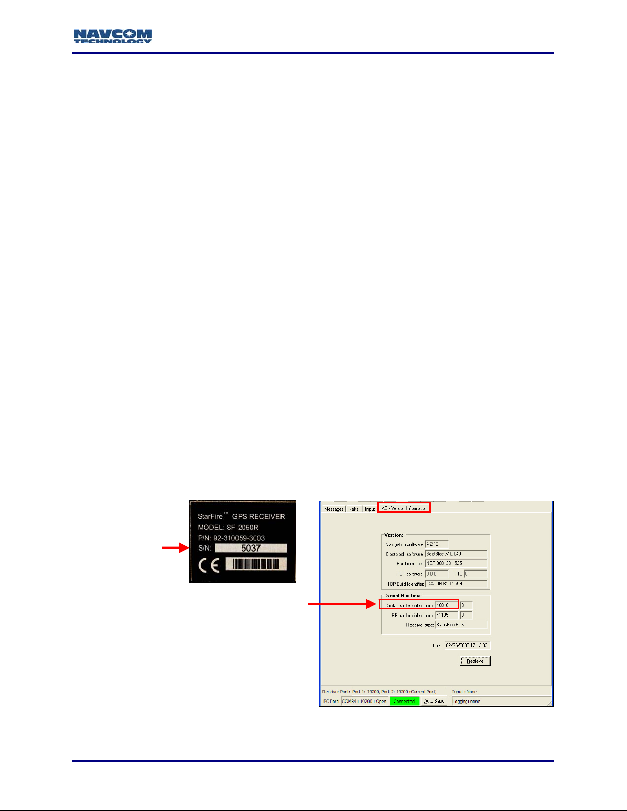
Determine StarUtil Version & Run StarUtil
The GPS unit serial number or the GPS digital card serial number is used to determine the
StarUtil version to install.
9 Refer to Figure 1 to locate:
• The GPS unit serial number on the rear of the receiver
Or
• The digital card serial number if an old version of StarUtil is installed on the computer.
Open StarUtil and select View > AE - Version Information. A tab opens that includes the
digital card serial number.
Serial Number on
Rear of Unit
Digital Ca
Serial Number
rd
Figure 1: Unit & Digital Card Serial Numbers
1-13
Page 16

StarUtil User Guide – Rev. G
9 Refer to Table 1 to determine the correct StarUtil executable file for the GPS unit.
Table 1: Serial Numbers To Determine StarUtil Version
StarUtil Version
StarUtil-2000.exe < 40,000 < 5000 Version 1
StarUtil-2100.exe > 40,000 > 5000 Version 2
9 Insert the supplied CD-ROM into the CD-ROM drive. Locate the executable file,
StarUtil-2100.exe or StarUtil-2000.exe, and save it to a folder on the PC. Double-click the
appropriate executable file to run StarUtil.
Digital Card
Serial Number
Unit
Serial Number
Software Options Type
Both versions of StarUtil share most of the same features, but are not
interchangeable. StarUtil will not function properly if the incorrect version is
installed.
9 Uninstall any old version of StarUtil if resident on the computer.
To load GPS software options, such as faster navigation rates (10Hz >), the user
must know the Software Options Type shown in Table 1. Refer to the section,
Load Purchased Software Options, in Chapter 9 for details.
1-14
Page 17
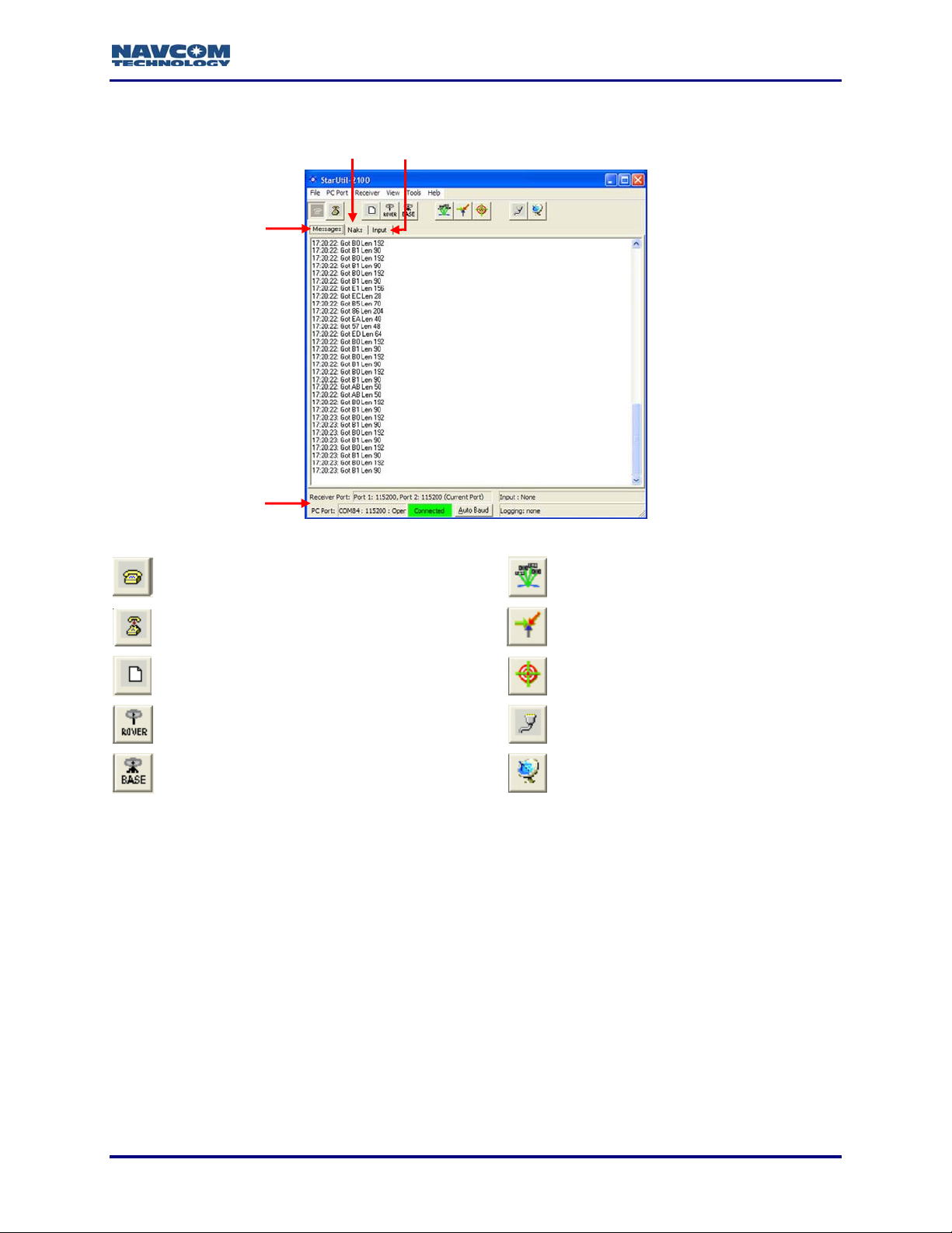
StarUtil GUI
StarUtil User Guide – Rev. G
Messages Tab
(NCT Binary
Messages)
Naks Tab Input Tab
Status Bar
Figure 2: StarUtil Window
Configure PC COM Port (see Figure 5)
View Satellite Status - Message 0x86
(see Figure 93)
Close PC COM Port View B1 Solution (see Figure 95)
Configure Data Logging (see Figure 104) View B1 Solution Plot (see Figure 96)
Configure Receiver Rover / Navigation &
Tracking Settings (see Figure 16)
Configure Receiver Base Settings (see
Figure 9)
Configure Receiver Ports (see Figure 7)
Configure Vertical Antenna Bias
(see Figure 21)
1-15
Page 18

StarUtil User Guide – Rev. G
StarUtil Main Functions
Configure Base Station And Rover
This user guide provides information in two ways to configure the base station and rover:
9 Reference Chapters:
• Chapter 3
contains most (but not all) of the controls that enable the receiver to operate as a base
station.
• Chapter 4
window. The window contains most (but not all) of the controls that enable the receiver
to operate as a rover.
9 Step-by-Step RTK Configuration:
• Chapter 5
station and the rover via internal or external radios, plus steps to verify the successful
communication of corrections. RTK Configuration involves the use of multiple windows:
Base Configuration, Rover / Navigation & Tracking Setup, Unit Port Configuration, etc.
This chapter highlights NCT RTK configuration, but also includes setup information for
RTCM, CMR and CMR+ corrections. Basic hardware setup is described.
Setup Message Output Lists
StarUtil provides the user with two windows to schedule and configure messages for output
according to application requirements:
9 NCT Binary Messages Window (see Figure 86)
9 NMEA Messages Window (see Figure 100)
: A reference of all the options on the Base Configuration window. The window
: A reference of all the options on the Rover / Navigation & Tracking Setup
: Step-by-step procedures to set up RTK communications between the base
The factory default for the GPS receiver is to output 7 NCT binary messages via
the Control Port 2, and 2 NMEA messages via the Data Port 1. The user has full
control over the utilized message types and their associated rates. Refer to
Chapter 7 Setup Message Output Lists
for details.
The Technical Reference Manual (TRM) details all NCT binary messages that
can be output from the receiver (see Related Documents in the fore-matter).
View Message Output
9 View Menu: Provides access to output of common NCT Binary Messages (see Figure 91)
9 NMEA Viewer: View output of scheduled NMEA Messages (see Figure 115)
Log Message Output
9 External Data Logging: Log the data from scheduled NCT Binary Messages continuously in
a single file or in 24-hour data file splits (see Figure 104)
9 MMC Internal Data Logging: Refer to the section, Log NCT Binary Data Internally Via
Memory Module Card (MMC), in Chapter 8.
9 NMEA Viewer: Log the data from scheduled NMEA Messages (see Figure 116)
1-16
Page 19

StarUtil User Guide – Rev. G
StarFire™ Operation
Load or cancel the license for the StarFire™ subscription service. StarUtil also provides
functions and data pertinent only to StarFire™ enabled receivers. Refer to Chapter 6 StarFire™
Operation.
Load Software
Load purchased software options and/or free software updates to the GPS receiver. Refer to
Chapter 9 Load Software
.
Configuration Reset
Select Receiver > Commands > Configuration Reset from the menu bar to reset the GPS
receiver to factory default settings. This command does not reset the position, time, almanac,
and ephemeris, but resets all other user settings to the factory default.
How Changes to Settings are Applied & Output Data Is Polled
The Apply and Retrieve buttons are at the bottom of most windows in StarUtil (see Figure 3).
StarUtil resides on the PC and allows the user to make changes which are not activated on the
receiver until after the Apply button is clicked.
The user clicks the Apply button to apply one or more new settings, and then clicks the Retrieve
button to confirm that the receiver accepts the setting(s).
Figure 3: Apply and Retrieve Buttons
StarUtil displays output data in two ways (see Figure 4):
9 Data is continuously updated for some scheduled messages, for example, B0-Raw
Measurements. StarUtil does not automatically poll the receiver for content. The user must
schedule the proper message(s) for output to view the data.
9 Some screens allow the user to poll for data to populate the screen. The user clicks the
Retrieve button, as on the 30-Software Options screen.
Figure 4: Examples of Output Data
1-17
Page 20

StarUtil User Guide – Rev. G
This page is left blank intentionally
1-18
Page 21
StarUtil User Guide – Rev. G
Chapter 2 ............................................................Establish Communications
This chapter provides instructions to:
9 Establish communications between a PC running StarUtil and the GPS receiver
9 Configure unit ports
Establish Communications
1. Connect the PC and the GPS receiver. Use the supplied data cable.
Refer to the Product User Guide for the appropriate model purchased for a list of the
equipment supplied with the GPS receiver.
2. Run the appropriate version of StarUtil on the PC. Refer to the section, Determine StarUtil
Version & Run StarUtil in Chapter 1.
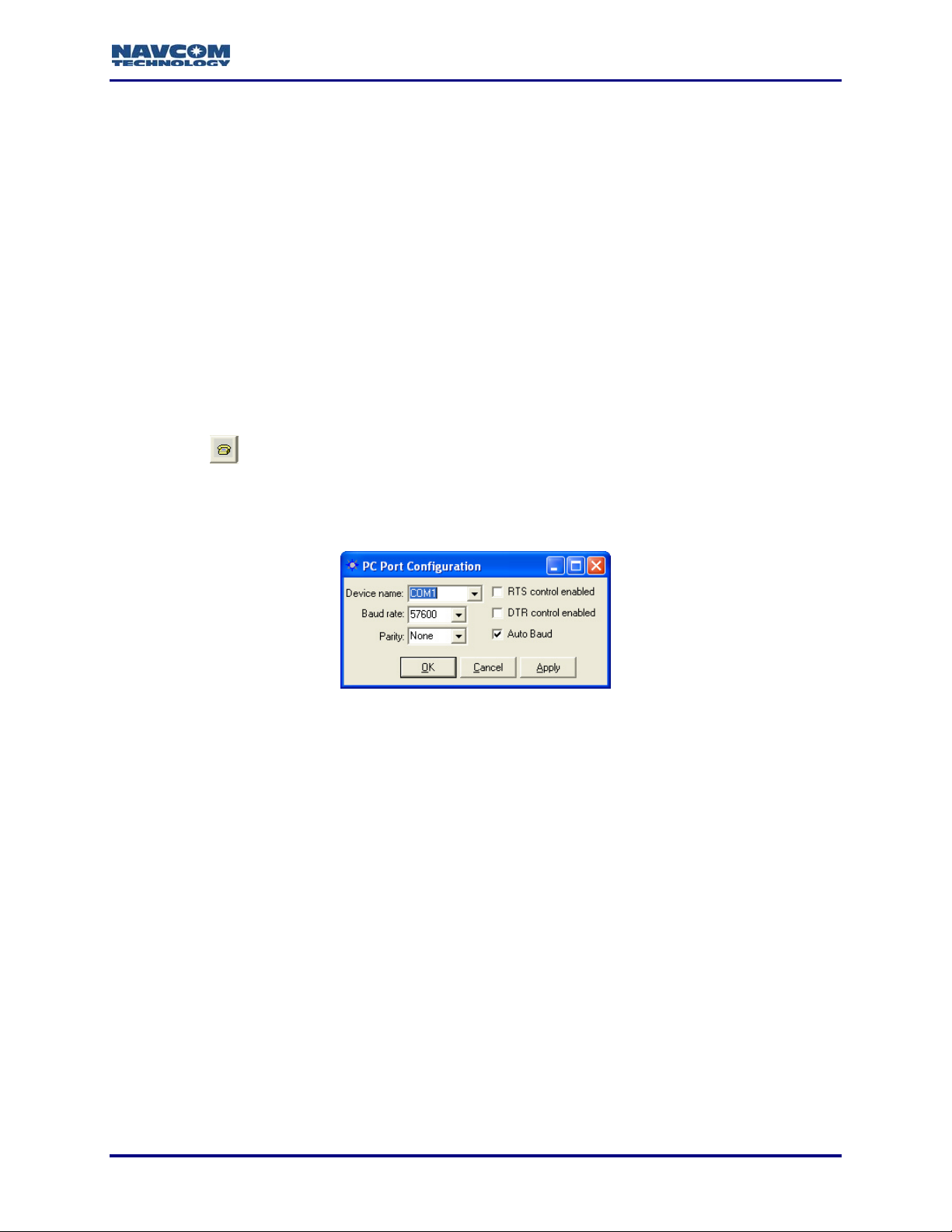
3. Click the
GPS receiver. The PC Port Configuration window opens (see Figure 5).
icon on the toolbar to establish communications between the PC and the
To open the window from the menu bar, select PC Port > Configure PC COM
Port.
Figure 5: PC Port Configuration Window
4. In the Device name drop-down list, select the PC COM port connected to the GPS receiver.
5. Accept the default option, Auto Baud, or uncheck the Auto Baud box and select a baud rate
from the drop-down list if the current receiver settings are known.
Auto Baud automatically detects the baud rate. If the user manually selects a baud
rate that does not match the current receiver settings, the connection will fail. To
change the receiver baud rate, refer to the section below, Configure Unit Ports.
6. Check both options together, RTS control enabled (Request To Send) and DTR control
enabled (Data Terminal Ready), as necessary, to configure the receiver and the computer to
acknowledge readiness before connection is established. This is optional and not required
by the GPS receiver.
2-19
Page 22
StarUtil User Guide – Rev. G
7. Click the OK button. If the connection is successful:
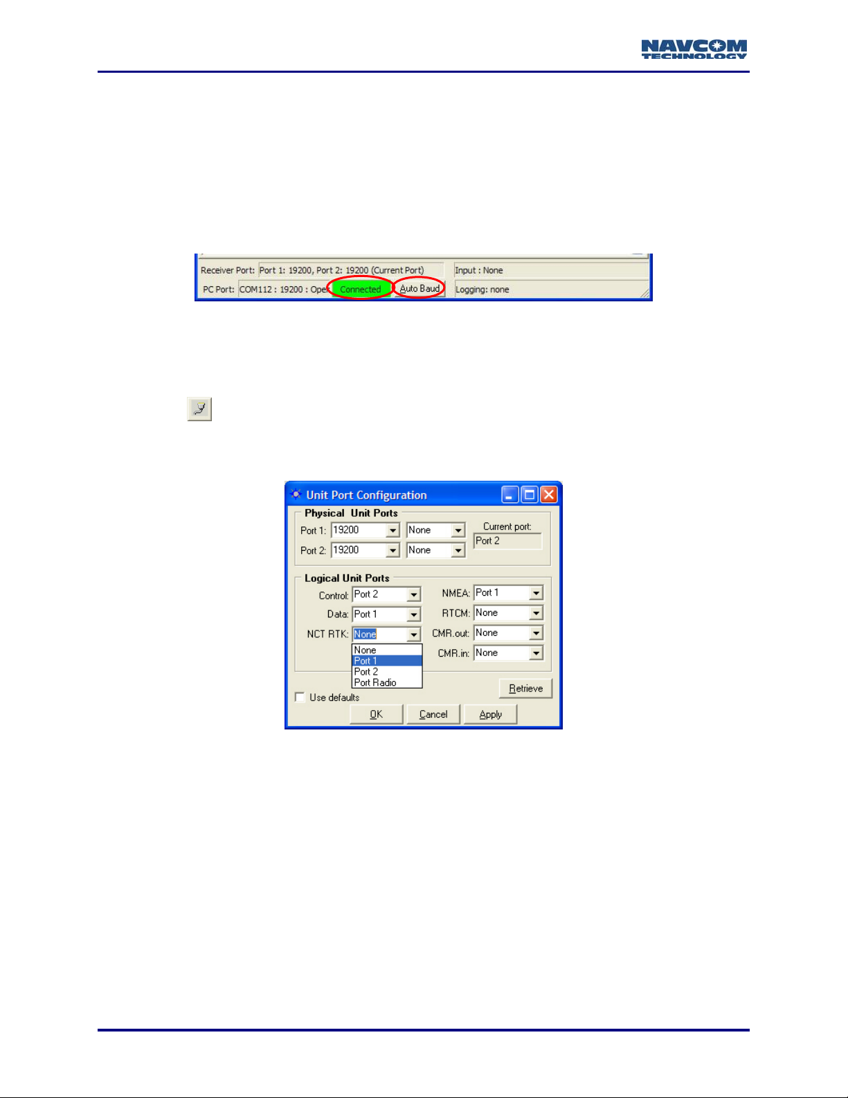
9 NCT Messages scroll down the Messages tab of the StarUtil window.
Refer to Figure 6 for a screen capture of the status bar.
9 The status bar at the bottom of the StarUtil window displays Connected in a green box. It
also provides connection information for both the receiver and PC ports.
9 The Auto Baud button in the status bar becomes active. If StarUtil becomes disconnected,
click the Auto Baud button to re-establish communications.
Figure 6: Status Bar
Configure Unit Ports
9 Click the icon on the toolbar to configure the physical and logical unit ports for specific
application requirements. The Unit Port Configuration window opens (see Figure 7).
To open the window from the menu bar, select Receiver > Setup > Ports.
Figure 7: Unit Port Configuration Window
Physical Unit Ports
9 Click the Port 1 and/or Port 2 drop-down lists to select a baud rate, and if necessary, select
the parity.
9 Click the Apply button and then click the Retrieve button to confirm that the receiver accepts
the new setting(s).
• If the receiver does not accept the new baud rate, the baud rate reverts to the previous
value. Click the Naks tab in the StarUtil window to view the error code.
• If the receiver accepts the new baud rate, it is retained in the field.
• If the Current Port baud rate is changed, Auto Baud attempts to reconnect at the newly
defined rate. Alternatively, the PC Port may require manual setting to the newly defined
2-20
Page 23

StarUtil User Guide – Rev. G
baud rate, or press the Auto Baud button in the Status Bar of the main window to
reconnect.
Logical Unit Ports
Refer to Figure 7 for the options below:
There are seven logical ports. The available port assignments are Port 1, Port 2, Port Radio, or
None. Port 1 is the equivalent of COM1. Port 2 is the equivalent of COM2. Port Radio must be
assigned to the internal radio models RT-3010 & RT-3020 only.
Logical Port Defaults:
9 Control: The default is Port 2.
9 Data: The default is Port 1.
9 NMEA: The default is Port 1.
NMEA messages must be output from the Data port. They cannot be output on
the same port that is used for Control. Refer to Chapter 8 Log Output Data/View
and Log NMEA Data for details.
The default for the RTK logical ports is None. Depending on configuration, these logical ports
are generally set to Port 1, except for models RT-3010 & RT-3020, which must be set to Port
Radio:
9 NCT RTK: Proprietary RTK and UltraRTK™
9 RTCM
9 CMR.out: Enables the output of CMR or CMR+ corrections
9 CMR.in: Enables the input of CMR or CMR+ corrections
Corrections can be simultaneously sent from the base station to any of the logical
ports, and also the internal MMC Memory Module for logging.
The factory default for the GPS receiver is to output 7 NCT binary messages via
the Control Port 2, and 2 NMEA messages via the Data Port 1. The user has full
control over the utilized message types and their associated rates. Refer to
Chapter 7 Setup Message Output Lists
for details.
2-21
Page 24

StarUtil User Guide – Rev. G
This page is left blank intentionally
2-22
Page 25
StarUtil User Guide – Rev. G
Chapter 3 ............................................ Base Configuration Window Options
This chapter is a reference of all the options on the Base Configuration window. This window
contains most (but not all) of the controls that enable the receiver to operate as a base station.
Refer to Chapter 5 RTK Configuration for step-by-step procedures to set up a
base station to transmit and a rover to receive RTK corrections via internal or
external radios.
Refer to the Technical Reference Manual for details of the control and output
messages that apply to RTK corrections (see Related Documents in the forematter).
Various Controls That Affect Base Station Operation
Depending on configuration, controls on these windows may affect base station operation:
9 Rover / Navigation & Tracking Setup Window:
• Min SV’s For Solution
• Max PDOP For Solution
• Max RTK Age
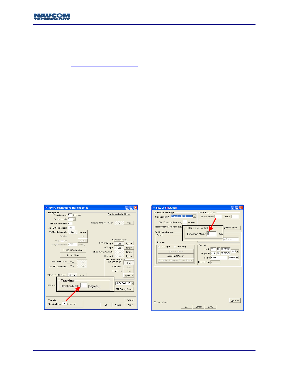
• Tracking Elevation Mask: if the rover Tracking Elevation Mask exceeds the RTK Base
Control Elevation Mask, tracking will not begin until the Tracking Elevation Mask is
reached. For example, if the Tracking Elevation Mask is 10 and the RTK Base Control
Elevation Mask is 5, RTK corrections won’t be computed until the satellite elevation
reaches 10 (see Figure 8).
Rover Tracking Elevation Mask
Figure 8: Elevation Mask Controls
3-23
RTK Base Control Elevation Mask
Page 26
StarUtil User Guide – Rev. G
9 53 – RTK Settings Window (see Figure 27): This window is available in StarUtil-2100 only.
If re-configuring a base station as a rover, check this window for settings that may need to
be changed. On the Rover / Navigation & Tracking Setup window, click the RTK Setting
Control button to access the 53 – RTK Settings window.
Models RT-3010 & RT-3020 Only (with internal radio):
9 Radio Configurations Window (see Figure 67): Operation Mode must be set to 1= Master,
Point to Multipoint to enable the receiver to operate as a base station.
9 Unit Port Configuration Window (see Figure 66): Depending on configuration, the NCT RTK
logical port, RTCM logical port, or CMR.out logical port must be set to Port Radio to enable
the base station to communicate with the rover via the internal radio.
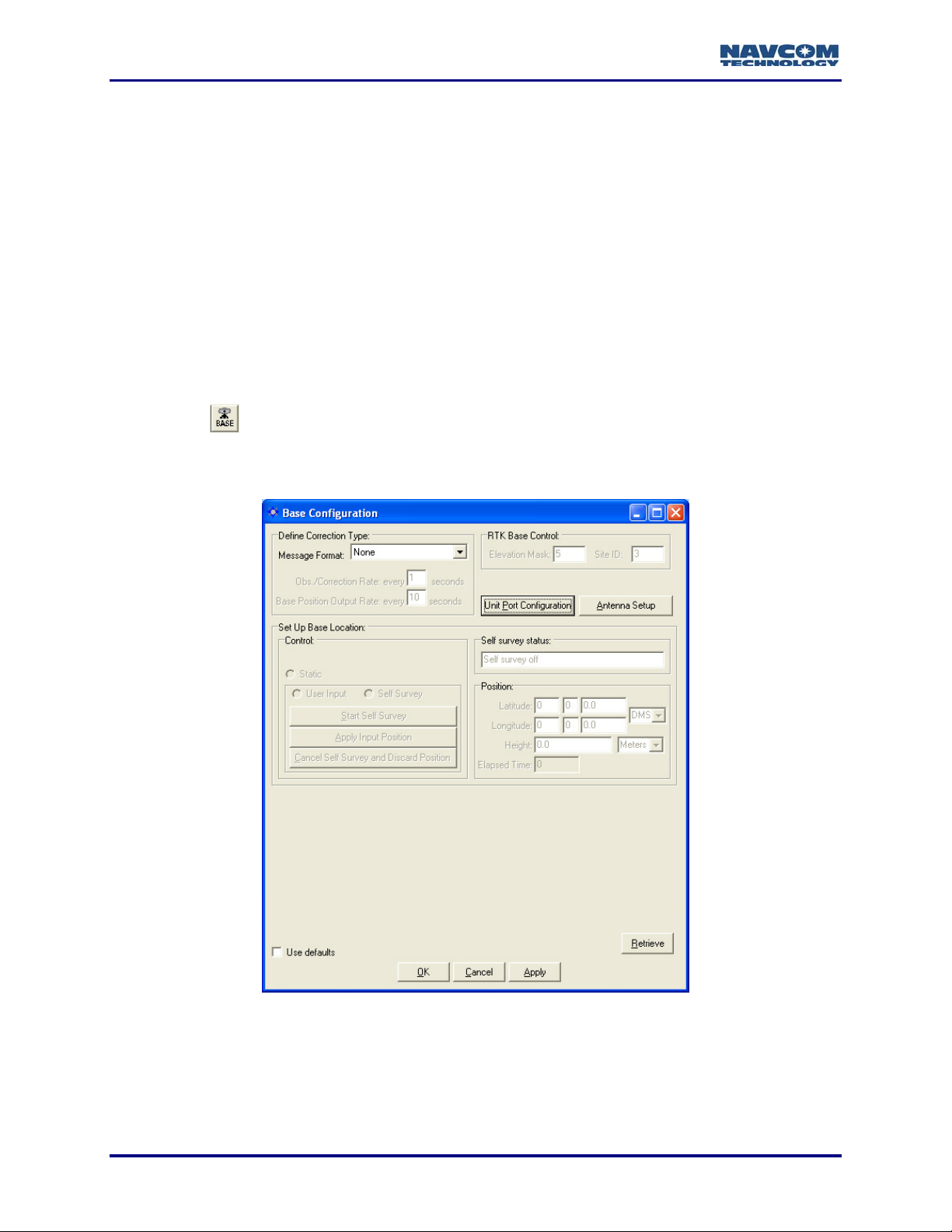
Base Configuration Window
9 Click the icon on the toolbar to configure the base station. The Base Configuration
window opens (see Figure 9).
To open the window from the menu bar, select Receiver > Setup > Base.
Figure 9: Base Configuration Window
After making settings in the sections below, click the Apply button and then click
the Retrieve button to confirm that the receiver accepts the settings.
3-24
Page 27

StarUtil User Guide – Rev. G
Define Correction Type
Figure 10: Base Configuration – Define Correction Type
Refer to Figure 10 for the options below:
9 Message Format: The available RTK correction types.
Proprietary (RTK) is for surveys under 10 km. Proprietary Long Baseline
(UltraRTK™), is for surveys from 10 km to 40 km.
9 Obs./Correction Rate: Do not change the default, every 1 second. It is the optimum rate.
CMR+ (RTK) is set at a pre-determined rate that can not be changed.
9 Base Position Output Rate: Do not change the default, which is the optimum rate. The
default for Proprietary (RTK) and Proprietary Long Baseline (UltraRTK™) is every 10
seconds. The default for all RTCM message formats and CMR (RTK) is every 10
corrections. CMR+ (RTK) is set at a pre-determined rate that can not be changed.
Proprietary (RTK) and Proprietary Long Baseline (UltraRTK™) only:
• The option, Obs./Correction Rate, applies to:
• Message 0x5B for Proprietary (RTK)
• Message 0x5E for Proprietary Long Baseline (UltraRTK™)
• In either configuration, the option, Base Position Output Rate, applies to message
0x5C.
When the base is configured for Proprietary RTK, messages 0x5B and 0x5C are
automatically scheduled for output in the NCT Binary Messages window. When
the base is configured for Proprietary Long Baseline (UltraRTK™), messages
0x5E and 0x5C are automatically scheduled for output in the NCT Binary
Messages window. In either configuration, message 0x5D is also scheduled for
StarFire™ enabled receivers. For details, refer to Chapter 5 RTK
Configuration/Verify Base Configuration.
Refer to the Technical Reference Manual for message details (see Related
Documents in the fore-matter).
UltraRTK™ is only available for and compatible with the NCT-2100D family of products.
3-25
Page 28
StarUtil User Guide – Rev. G
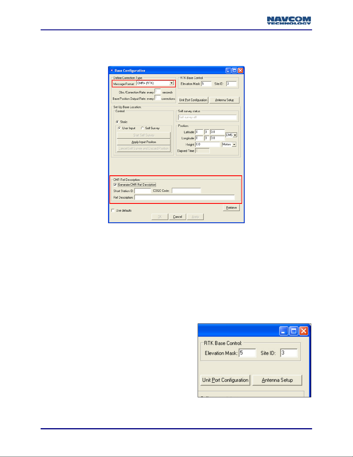
Additional Controls For CMR+
When the message format CMR+ (RTK) is selected, the Base Configuration window displays
additional controls (see Figure 11). The same controls for CMR (RTK) are not active.
Figure 11: CMR Ref Description
Refer to Figure 11 for the options below:
9 Generate CMR Ref Description: Click the check box to activate the fields.
9 Short Station ID: Enter the Short Station ID / Name.
9 COGO Code: Enter the reference station point feature code to be transmitted.
9 Ref Description: The reference station description.
RTK Base Control, Unit Port Configuration, And Antenna Setup
9 Elevation Mask: Enter the cutoff vertical angle
above the horizon. For any satellites below this
angle, no data will be transmitted to the rover for
use in calculating positions.
The default recommended setting for the base
receiver is 5 degrees; however, the height of
on-site obstructions will dictate this setting.
Collecting poor data (i.e. through trees) at the
base will degrade the performance of the
rover.
3-26
Figure 12: RTK Base Control
Page 29
StarUtil User Guide – Rev. G
Refer to Figure 12 for the options below:
9 Site ID: Accept the default base Site ID (3) or enter an ID to isolate the base and rover
radios, if desired. The rover radio must be set to the identical ID. This avoids cross talk
between the rover radio and any other base radio in the area that may be set to the same
frequency. For multiple base stations, use a different site ID for each one. The valid range
for a Base site ID is 1 to 1023. The valid range for a Rover site ID is 0 to 1023. If the rover
Site ID is 0 (the default), the rover accepts RTK corrections from any base station (see
Figure 23).
Models RT-3010 & RT-3020 only (with internal radio): StarUtil provides a
Network ID option (see Figure 70).
9 Unit Port Configuration Button: Click this button to configure the physical and logical unit
ports. The Unit Port Configuration window opens. Refer to the section above, Configure Unit
Ports, for more information.
9 Antenna Setup Button: Click this button to set the appropriate bias adjustment values for the
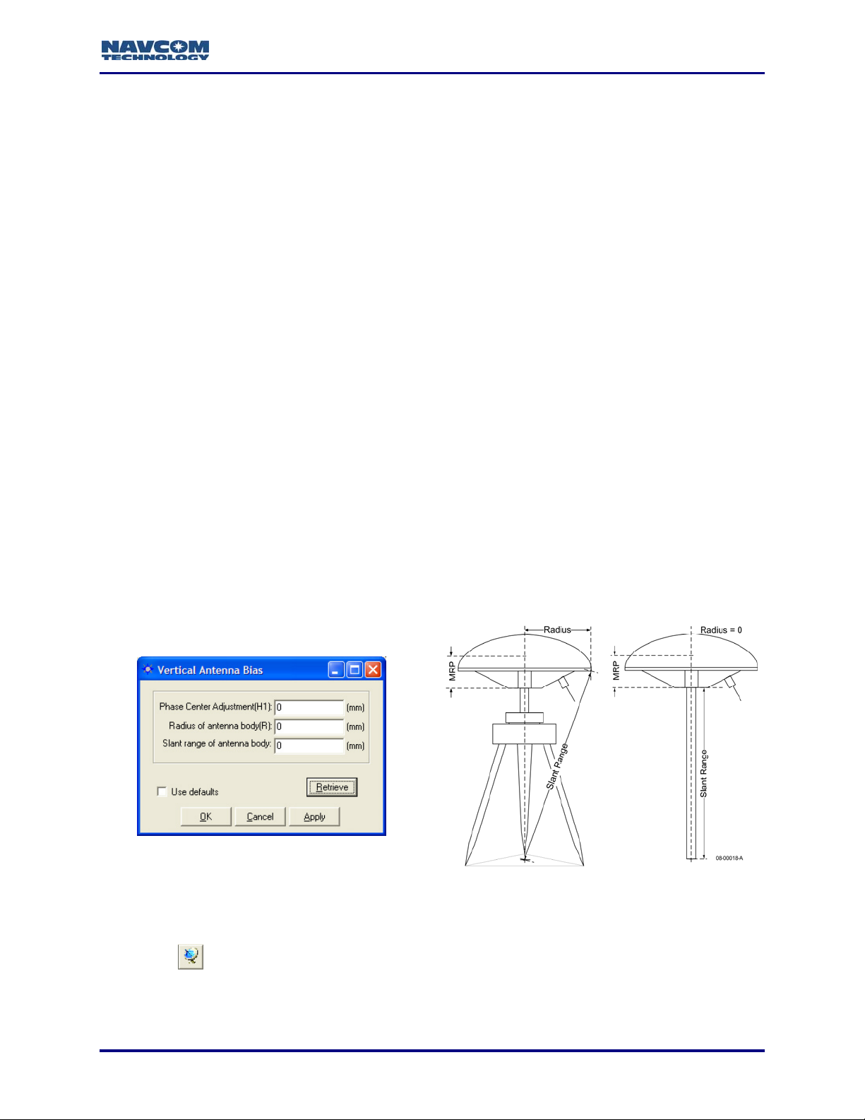
antenna model in use (optional). The Vertical Antenna Bias window opens (see Figure 13):
• Phase Center Adjustment (H1): The offset in millimeters from the physical center of the
antenna (the element) to the Mechanical Reference Plane (MRP). The MRP is at the
bottom of the BSW antenna mount. The range limits are -128 to 127mm.
• Radius of Antenna Body (R): The measurement in millimeters from the physical center of
the antenna to the edge of the antenna. For a pole, enter 0. For a tripod, the range limits
are -32768 to 32767mm.
• Slant Range of Antenna Body: For a pole, the vertical measurement in millimeters from
the Mechanical Reference Plane (MRP) to the control point. For a tripod, the
measurement in millimeters from the edge of the antenna to the control point. The range
limits are -32768 to 32767mm.
Figure 13: Vertical Antenna Bias
To access the Vertical Antenna Bias window from the main StarUtil window, click
the
3-27
icon or select Receiver > Setup > Vertical Antenna Bias.
Page 30
StarUtil User Guide – Rev. G
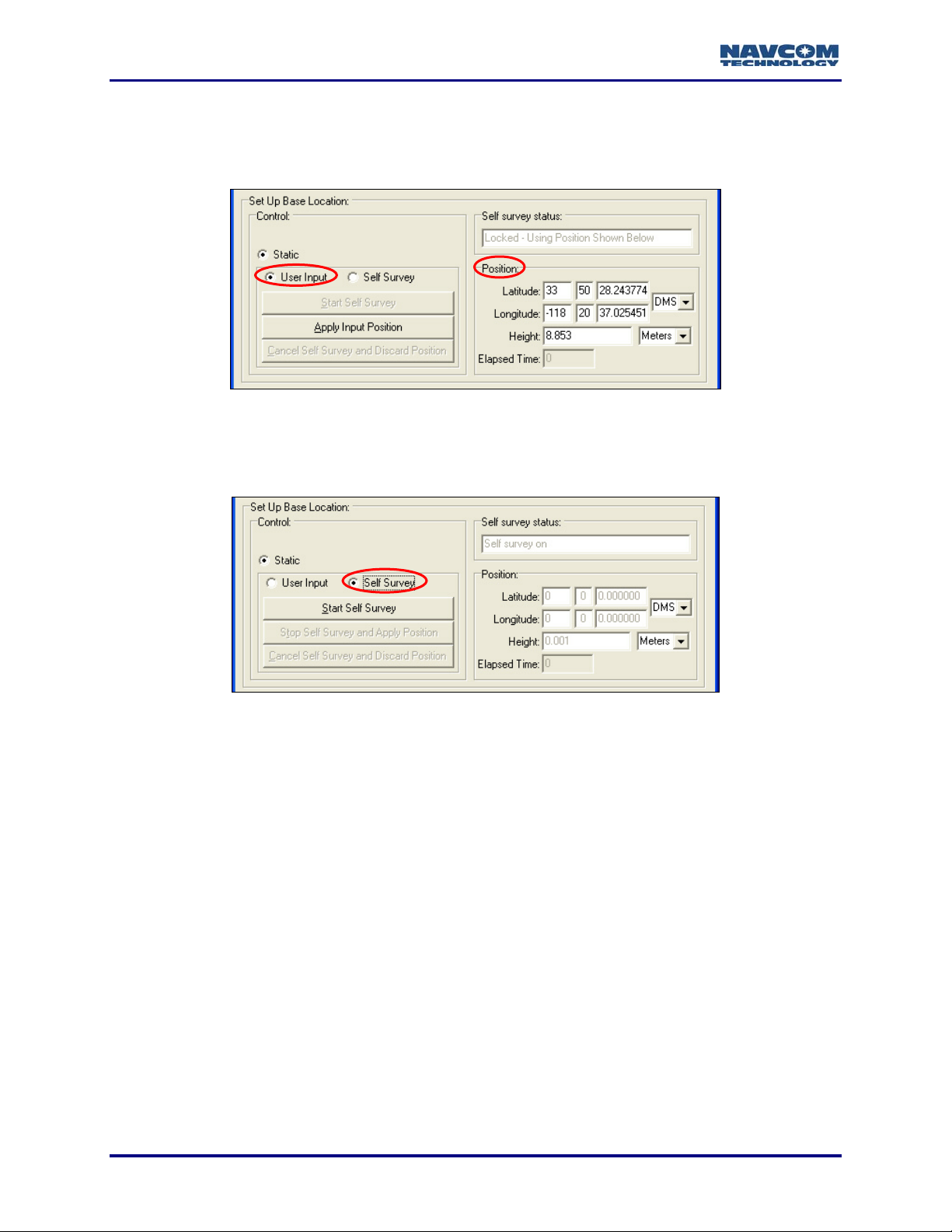
Set Up Base Location
Enter the position of the base station, manually via User Input (the default) or automatically via
Self Survey.
Figure 14: Base Location – User Input
9 User Input (the default): Manually enter the known surveyed truth position in the Position
section of the window (see Figure 14). Click the Apply Input Position button to save the
position in NVRAM.
Figure 15: Base Location –Self Survey
Refer to Figure 15 for the option below:
9 Self Survey:
• Click the radio button next to Self Survey.
• Click the Start Self Survey button to obtain a position from the received GPS signals.
The time of survey varies and average position is used. For best results, allow
the receiver to run several hours (minimum of 10 minutes). Errors in the base
position will apply an equal bias error in the rover position
• Click the Stop Self Survey and Apply Position button to save the position in NVRAM.
This sends the 0x51 message to the receiver, which contains only the averaged
base antenna location parameters.
• Click the Apply button at the bottom of the window.
This sends the 0x50 message, and as appropriate, messages 0x56, 0x5A, and/or
0x5C. The base is configured to send RTK corrections to the rover.
3-28
Page 31

StarUtil User Guide – Rev. G
Chapter 4 .................Rover / Navigation & Tracking Setup Window Options
This chapter is a reference of all the options on the Rover / Navigation & Tracking Setup
window. This window contains the navigation mode and operational controls to configure the
rover. The options apply to messages 0x47 (SV Tracking Control) and 0x49 (Solution Control).
Refer to Chapter 5 RTK Configuration for step-by-step procedures to set up a base
station to transmit and a rover to receive RTK corrections via internal or external radios.
The available navigation modes on the Rover / Navigation & Tracking Setup window are:
9 RTCM-104 (code)
9 WCT: Not applicable as of January 2008
9 SBAS (WAAS/EGNOS/MSAS/GAGAN): RTCA/DO-229D compliant. Refer to Related
Standards in the fore-matter.
9 RTG: Access to this mode is available only by purchase of a license for the StarFire™
subscription service. Refer to Chapter 6 StarFire™ Operation
9 RTK: RTK/UltraRTK™-NCT Proprietary, CMR, RTCM – Access to this mode is available
only by purchase of a license.
.
9 Non-differential mode: The default if all the navigation modes above are set to Ignore.
Rover / Navigation & Tracking Setup Window
9 Click the icon on the toolbar to configure the rover. The Rover / Navigation & Tracking
Setup window opens (see Figure 16).
To open the window from the menu bar, select Receiver > Setup > Rover /
Tracking and Navigation.
Figure 16: StarUtil-2100 -- Rover / Navigation & Tracking Setup Window
4-29
Page 32

StarUtil User Guide – Rev. G
The options on the Rover / Navigation & Tracking Setup window are identical in
StarUtil-2000 and StarUtil-2100, except for the RTK Setting Control button, which
is included only in StarUtil-2100 (see Figure 16).
After making any settings in the sections below, click the Apply button and then
click the Retrieve button to confirm that the receiver accepts the settings.
Navigation Rate and Other Options
9 Elevation Mask: Enter a value between 0 and 90 degrees
to set the elevation angle at which the receiver will start
processing GPS data from satellites.
The default elevation mask is 7 degrees to prevent
position jumps due to frequent satellite re-acquisitions
at lower elevation mask angle limits.
Figure 17: Elevation Mask & Nav Rate
9 Navigation Rate: The number of navigation solutions per second. The standard rates are
1Hz (default), 2Hz, and 5Hz. Purchased software options are 10Hz and above, with the
exception of the VueStar system for which all available rates are standard. The upload of a
purchased navigation rate changes the setting in the Navigation rate field automatically to
the purchased rate. Refer to Chapter 9 Load Software
and upload of software options.
for information about the purchase
The Navigation Rate setting in the Rover / Navigation & Tracking Setup window
sets the output of the NCT Binary message B1 and the NMEA messages GGA,
RMC and VTG, provided that those messages are set to On Change in the NCT
Binary Messages window and the NMEA Messages window, respectively (see
Figure 18).
For the NCT Binary message B0 only, the rate of On Change (the default) is 1Hz
regardless of the navigation rate setting. To set the output of B0 at a higher rate to
match the output of B1, use the NCT Binary Messages window. The rate must be
a purchased navigation and raw data rate (refer to message 0x30 in the Technical
Reference Manual).
4-30
Figure 18: Navigation Rate
Page 33

StarUtil User Guide – Rev. G
When a message is set to On Change, the data is output each time new data is
available as determined by the Navigation Rate setting (see Figure 18). For
example, if a position is steadfast at N 33
three seconds and the Navigation Rate is 5Hz, a 0xb1 solution is output 1 time
because the position didn’t change. If any element of the position changes
continuously during the three second period then a 0xb1 solution is output 15 times.
The NMEA messages GGA, RMC, and VTG match the
output of the navigation rate up to 10 Hz max when
scheduled as On Change.
Min SVs for Solution: The default setting is three satellites.
9
Four satellites are the minimum SVs required for a 3D
navigation solution, plus an ac
ax PDOP for Solution: The maximum PDOP value at
9 M
which the receiver will compute positions is 25.5. Enter the
highest PDOP value according to application requirements.
An applied value above 25.5 reverts to the default of 10.0.
ceptable PDOP.
º
50’20.18592” W 118º 20’35.21218” for
The default setting for Max PDOP is 10. The quality of GPS data is depende
the geometry between the receiver and satellites; this includes the number of
satellites that can be "seen" by the receiver and the angle between the receiver
and satellites as a constellation seen by the receiver. A s
usually provides a lower quality signal because of gr
interference and the increas
features; this is known as "multipath" error. The effect of
quality is measured by PDOP (position dilution of precis
measure of the precision obtainable with a given sa
a PDOP of 4 or less yields excellent precision,
acceptable and a PDOP of 7 or more is considered p
9 2D/3D Solution Mode: Click the Auto or Manual button to det
applied to a 2D navigation solution.
• Auto: Sets the receiver to automatically transition between 3D (4 satellite) and 2D (3
satellite) navigation. This can also be determined by DOP values, even if 5 satellite
available. In 2D navigation, the last valid computed height measurement is used
• Manual: Enter the Height hold value to set
the receiver to 2D (3 satellite) navigation
with the Height hold value used for the
height measurement. The receiver must
compute an initial 3D navigation solution
before it transitions to 2D navigation. After
2D navigation is established, the receiver
will not transition back to 3D navigation.
likelihood of the signal reflecting from surface
ed
a PDOP between 5 and 7 is
atellite near the
eater atmospheric
geometry on GPS
ion). PDOP is the overall
tellite geometry. For ex
oor.
ermine how height will be
horizon
ample,
nt on
s are
.
Click the icon in the toolbar to view the
current navigation solution and other
parameters of message 0xB1. The 3D nav
field indicates if 3D navigation is computed
(see Figure 19).
Figure 19: B1 – Solution, 3D nav Field
4-31
Page 34

StarUtil User Guide – Rev. G
Figure 20: Rover / Navigation & Tracking Setup Window
9 Unit Port Configuration Button:
ports. The Unit Port Configuration
above, Configure Unit Ports
9 Antenna Setup Button: Click th
antenna model in use (o
• Phase Center Adjustment (H1): The offset in millimeters from the physical center of the
antenna (the element) to the Mechanical Reference Plane (MRP). The MRP is at the
bottom of the BSW antenna mount. The range limits are -128 to 127mm.
• Radius of Antenna Body (R): The measurement in millimeters from the physical center of
the antenna to the edge of the antenna. For a pole, enter 0. For a tripod, the range limits
are -32768 to 32767mm.
• Body: For a pole, the vertical measurement in millimeters from
Slant Range of Antenna
the Mechani d, the
measureme l point. The range
limits are -32768 to 32767mm.
cal Reference Plane (MRP) to the control point. For a tripo
nt in millimeters from the edge of the antenna to the contro
ptional). The Vertical Antenna Bias window opens (see Figure 21):
A label on the bottom of NavCom supplied ante
measurements for the antenna in use.
Click this button to configure the physical and logical unit
window opens (see Figure 20). Refer to the section
, for more information.
is button to set the appropriate bias adjustment values for the
nna’s provides the appropriate
4-32
Page 35

Figure 21: Vertical Antenna Bias
StarUtil User Guide – Rev. G
he Vertical Antenna Bias window from the main StarUtil window, click
9 Use Antenna Bias: Click the Yes or No button to determine if the values set in the Vertical
9 Use SET Corrections: Click the Yes or No button to determine if Solid Earth Tide (SET)
To access t
the
Antenna Bias window are applied to measurements.
corrections are applied to measurements.
Requirements for output of SET corrections:
• Message 0x49, W6 B6 set to Apply Correction
• NCT SET scheduled for output in the NMEA
Messages window (see Figure 22)
A license for the StarFire™ subscription service.
•
The option, RTG input, must be set to Use on
the Rover / Tracking & Navigation Setup
window.
• Valid Navigation
• Valid SET correctors (A minimum of 1 run of the
SET algorithm. These are an integral part of
StarFire™ corrections.)
icon or select Receiver > Setup > Vertical Antenna Bias.
Figure 22: NCT SET
If the criteria above are met, the receiver applies the
solution. The B1 Solution tab displays SET North
(see Figure 19, lower left corner).
SET refers to Solid Earth Tides. Positions with SE
(primarily) and horizontal positioning accuracy,
placed on terrain from celestial bodies (i.e
The SET message
message. It conform
standard NMEA string, but is not recognized by the NMEA governing body as an
4-33
output via the NMEA port is a NavCom proprietary NMEA type
s to the header, checksum, and electrical characteristics of a
. the Sun, Moon, etc.).
SET corrections to the position
, East, and Up corrections in millimeters
T provide better vertical
to account for gravitational effects
Page 36

StarUtil User Guide – Rev. G
officially sanctioned message. Refer to Appendix A, Table 12 for a detailed description of
the NMEA Type message structure.
Navigation
Elevation Mask
Tracking
Elevation Mask
Figure 23: Rover / Navigation & Tracking Setup Window
Refer to Figure 23 for the options below:
9 CMR/RTCM 18 Phase: The default is Normal. In a small number of instances, there is a
requirement to receive the RTCM phase corrections in an “inverted” state. Click the Invert
button. StarUtil will correct the sign of the corrections automatically so they may be applied
without prejudice.
9 Site ID: The default 0 co rover to accept RTK corrections from any base station.
Enter a specific Site only from the base station with the same
Site ID. The default Site I ation window is 3 (see Figure 12).
9 RTCM Station ID: ver to accept corrections from any RTCM
The default 0 configures the ro
Station. Enter a specif ns only from that RTCM
nfigures the
ID to accept RTK corrections
D on the Base Configur
ic RTCM Station ID to accept correctio
Station.
9 Max RTK Age: E d correction will be
used in case of an outage or drop in th
the max RTK age limit, which is 60 se
nter the maximum amount of time in seconds the receive
e reception of corrections. The time must be within
conds. The default is 15 seconds. If the age is less
than the rate of corrections received, the rover will not enter RTK mode.
9 Max dGPS Age: Enter the maximum amount of time in seconds the received correction will
be used in case of an outage or drop in the reception of corrections. The time must be within
the max dGPS age limit, which is 1200 seconds. The default is 300 seconds.
Tracking
9 Elevation Mask: Enter a value to set the elevation angle at which the receiver will start
tracking satellites. The default is 0. The valid range is between 0 and 90 degrees, but a
value higher than 10 is not recommended. The GPS data from the tracked satellites is not
added to the navigation solution. In contrast, the Navigation/Elevation Mask
4-34
setting sets the
Page 37

StarUtil User Guide – Rev. G
elevation angle at which the receiver will start processing GPS data to be added to the
navigation solution.
Special Navigation Modes
9 Require dGPS for Solution: The default is No which
indicates that all computed position solutions are output
whether differentially corrected or not. Click the Yes button
to require only dGPS for solution.
Navigation Mode
9 RTCM-104 Input, WCT Input, SBAS
[WAAS/EGNOS/MSAS/GAGAN], and RTG Input: The
default for all the navigation modes is Use.
• Access to RTG input is available only by purchase of a
license for the StarFire™ subscription service. Refer to
Chapter 6 StarFire™ Operation
• WCT input is not applicable as of January 2008.
• Click the Ignore button to disable a navigation mode.
.
• Click the Ignore button for all the navigation modes to
operate in non-differential mode.
Figure 24: Navigation Modes
StarUtil provides the option to manually enter two L1 SBAS satellite Prns from
which to receive c
details.
RTK Correction Format:
9 RTK (5B, 5C, 5E), CMR Input, and RTCM RTK: The defa
• Click the Use button to apply a RTK correction format to the navigation solution.
RTK (5B, 5C
formats. Refer to the Technical Reference Manual
5C, and 5E (see Related Docume
CMR Input enables the input of CMR or C
orrections. Refer to the section below, WAAS Prn Selection, for
is Ignore All.
ult
, 5E) is the setting for the NavCom propriety RT
for details on messages 5B,
nts in the fore-matter).
MR+ corrections.
K and UltraRTK™
4-35
Page 38

StarUtil User Guide – Rev. G
GGA Option
9 GGA Option: Determine how a GGA message is output:
• NMEA Station ID: Ac
conforms to the NME
• NCT Station ID: Select this option to populate the Differential Referenc
with values that indicate which StarFire™ satellite is being tracked (1st digit) and
navigation mode (2nd digit). See Appendix B
cept this default option to output a GGA message that strictly
A Standard v3.01.
e Station ID field
for the NCT Station ID matrix.
The differential reference station is field 14 in the NMEA GGA message.
Figure 25: GGA Option
RTK Setting Control Button (StarUtil-2100 only)
9 Click the RTK Setting Control button to apply a variety of
RTK settings to message 0x53. The 53 – RTK Settings
window opens (see Figure 27). Message 0x53 is described
in detail in the Technical Reference Manual.
Figure 26: RTK Setting Control Button
the
To open the Setup > RTK > RTK Settings.
When re-configuring the window for
settings that may need t
window from the menu bar, select Receiver >
receiver, check the 53 – RTK Settings
o be changed.
Figure 27: 53 – RTK Settings Window
After making one or more settings, click the Apply button and then click the
Retrieve button to confirm that the receiver accepts the setting(s).
4-36
Page 39

Refer to Figure 27 for the options below:
StarUtil User Guide – Rev. G
9 RTK Estimation Type: Select the type of position smoothi
• Static: Not moving
• Stationary: Very low velocity; e.g., walking
• Low Velocity: Slow moving vehicle; e.g., agriculture or road construction vehicle
• High Velocity: Faster moving vehicle; e.g., car or aircraft
ultipath Environment: Select the tolerance for tracking and acquisition.
9 M
9 RTK Time Synchronization:
• Low Latency: Data is output as quickly as it is calculated.
• Time Synchronized: Data is output at periodic intervals.
9 RTK Ambiguity Solution:
• Fixed: Phase and code RTK
• Float: Code RTK Ambiguity Solution only
9 Cutoff Angle (deg.): The cutoff angle in degrees for measurements. The default 7 degrees is
recommended. Never enter a cutoff angle higher than 15 d
9 Ambiguity Resolution Cutoff Angle (deg.): The cutoff angle in
The default 10 degrees is recommended.
Ambiguity Solution
speed
ng for the required application:
egrees.
degrees for ambiguity search.
9 Max Base Data Age (s): The RTK maximum age to use b
nge is 0 – 1200 seconds. The default is 300 seconds.
ra
9 Ambiguity Resolution Max Base Data Age (s): The maximum base station data age for
biguity resolution search or for fixed ambiguities. The valid range is 0 – 120 seconds. The
am
default is 15 seconds.
9 Use Defaults: Click the check box to use the
default settings.
ase station correction. The valid
Verify Reception of RTK Corrections
Refer to these sections in Chapter 5 RTK Configuration for instructions to verify that the rover is
receiving RTK corrections from the base station:
9 Verify Reception of NCT RTK Corrections
9 Verify Reception of RTCM RTK Corrections
9 Verify Reception of CMR RTK Corrections
4-37
Page 40

StarUtil User Guide – Rev. G
WAAS Prn Selection
The WAAS Prn Selection window enables the user to manually configure the receiver to receive
corrections from one or two L1 SBAS satellites.
The WAAS Prn Selection window is functional for
with the RTCA/DO-229D standard: WAAS, EGNOS, MSAS, and GAGAN. Refer
to Related Standards in the fore-matter.
Figure 28: WAAS Prn Selection Window
9 Select Receiver > Setup > Select WAAS Prns. The WAAS Prn Selection window opens (see
Figure 28).
9 Enter one or two L1 SBAS satellite Prns.
all SBAS systems that comply
9 Determine the use of th
• Manual Mode: Always use the entered prns.
• Auto Mode: Use the prns if the receiver doesn’t have a valid position fix. The receiver will
update the SBAS prns to use after it h
e Prns:
as a valid position.
4-38
Page 41

StarUtil User Guide – Rev. G
Chapter 5 ......................................................................... RTK Configuration
This chapter provides step-by-step procedures to set up a base station to transmit and a rover
to receive RTK corrections via internal or externa
9 NCT RTK or UltraRTK™
9 RTCM
9 CMR / CMR+
l radios:
Refer to Chapter 3 Base Configuration Window Options
station controls. Refer to Chapter 4 Rover / Navigation & Tracking Setup Window
Options for a reference of rover controls.
for a reference of base
Ambiguity Resolution
Ambiguity resolution, or the ability to enter RTK navigation mode, requires:
9 Four or more satellites, with good geometry, above the Navigation Elevation Mask
• Good satellite geometry means the satellites should fall, one each, in each of four quadrants.
• Satellite geometry is characterized by the PDOP value. The closer the value is to 0, the
better the satellite geometry. The default maximum PDOP value is 10.
Hardwar
The hardware can be setup ver systems which d
incorporate an internal radio modem, the setup within the receiver is the same regardless of the
DGPS correction physical interface (external radio modem, packet data cell phone/modem,
Iridium satellite modem, Bluetooth, o
on the RT-3010 & RT-3020 models only.
e Setup
in any number of combinations. For recei
r null-modem cable). The internal radio option is available
o not
Figure 29: Traditional Radio Modem Hardware Interface
5-39
Page 42

StarUtil User Guide – Rev. G
Table 2: Typical Radio Modem Interface
Manufacturer Baud Band (MHz) Bits Stop Bits Parity
Satel 9600 450 / 900 8 1 None
Microhard 9600 2,400 8 1 None
Freewave 9600 900 / 2,400 8 1 None
Pacific Crest 38400 450 / 900 8 1 None
External Radio Setup
Connect and setup the radio modem or other DGPS correction medium per the manufacturer’s
instructions.
9 Set the RTK correction data link at both ends to the same data rates (i.e. 9600 bps default,
or 38400bps; 4800 bps minimum, slow data rates may increase correction latency), 8 bit, 1
stop bit, no parity.
9 Set the radio modems to the same frequency or frequency pair (depending on type of radio
modem)
9 Verify addressing (if used) and error correction modes are properly set in the radio modem
9 Verify Maste is set to Master)
9
Verify frequency hopping plan (if used) is set correctly on both radios.
9 ection
Verify the transmit power (base), receive sensitivity (if adjustable), and antenna conn
r / Slave settings (if used) are set correctly (the base station
are correct
9
Connect the radio modem to Com1 (Port 1 or Port A) on the GPS receiver
5-40
Figure 30: Example of a TruBlu & Bluetooth Controller Interface
Page 43

StarUtil User Guide – Rev. G
NCT RTK Configuration
This section provides steps to configure a base station and rover to use NCT RTK or
UltraRTK™ corrections:
9 Establish communications between the radio modem and the base GPS receiver via the
Unit Port
Configuration window
9 Set up Proprieta
position via the Base Configuration
9 Establish communications between the radio modem and the rover GPS receiver via
Unit Port Configuration window
9 Set up various navigation and RTK settings fo
Tracking Setup window
If an internal radio is used, perform the procedures below and also in
Configure Internal Radio. The Internal radio option is available on the RT-3010 &
RT-3020 models only.
ry RTK or UltraRTK™, RTK Base Controls, and establish the base station
window.
r the rover via the Rover / Navigation &
.
the section,
Base Port Configuration
Refer to Figure 31 for the steps below:
1. Click the
the GPS receiver. The Unit Port Configuration window opens.
icon on the een the radio modem and toolbar to set the communications betw
To open the window from the menu bar, select Receiver > Setup > Ports.
the
Figure 31: Base – NCT RTK Port Configuration
2. Set the baud rate, as appropriate, for Port 1 (19200 default). Do not change the default
parity (None).
3. Set the NCT RTK logical port to Port 1 (equivalent to Com1).
Models RT-3010 & RT-3020 only (with internal radio): Set the NCT RTK logical
port to Port Radio.
4. Click the Apply button and then click the Retrieve button to confirm that the receiver accepts
the settings.
5. Click the OK button to exit the window.
5-41
Page 44

StarUtil User Guide – Rev. G
Base Configuration
6. Click the icon on the toolbar to conf ase tion. T Base Configuration
window open ure 3
To open B
s (see Fig 2).
the window from enu t Receiver > S up > the m bar, selec et ase.
igure the b sta he
Figure 32: Base Configuration Window
Define Correction Type
Refer to Figure 32 for the steps below:
7. Depending on application requirements, select from the Message Format drop-down list:
• Proprietary (RTK): for surveys under 10km
or
• Proprietary Long Baseline (UltraRTK™): for surveys from 10km to 40km
UltraRTK™ is only available for and compatible with the NCT-2100D family of products.
8. Do not change the defaults for:
• Obs./Correction Rate: every 1 second (the optimum rate)
• Base Position Output Rate: every 10 seconds (the optimum rate)
The option, Obs./Correction Rate, applies to message 0x5B for Proprietary (RTK)
or messa
configuratio
Refer to the Technical Reference Manual for message details (see Related
Documents in the fore-matter).
ge 0x5E for Proprietary Long Baseline (UltraRTK™). In either
n, the option, Base Position Output Rate, applies to message 0x5C.
5-42
Page 45

StarUtil User Guide – Rev. G
RTK Base Control, Unit Port Configuration, And Antenna Setup
Figure 33: RTK Base Control
Refer to Figure 33 for the steps below:
9. Set the options if desired:
• Elevation Mask: Enter the cutoff vertical angle above the horizon. For any satellites
below this angle, no dat
a will be transmitted to the rover for use in calculating positions.
The default recommended setting for the base receiver is 5 degrees; however,
the height of on-site obstructions will dictate this setting. Collecting poor data (i.e.
through trees) at the base will degra
de the performance of the rover.
• Site ID: Accept the defa
radios, if desired. The rover radio
between the rover radio and any other base radio in the area
same frequency. For multiple base stations, use a different site ID for each one. The
valid range for a site ID is 0 to 1023. If the rover Site ID is 0
accepts RTK corrections from any base station (see Figure 47).
ult base Site ID (3) or enter an ID to isolate the base and rover
must be set to the identical ID. This avoids cross talk
that may be set to the
(the default), the rover
Models RT-3010 & RT-3020 only (with internal radio): StarUtil provides a
Network ID
provides a second method of differentiating multiple available networks.
Depending on configura Tracking
Setup window ma PDOP
For Solution,
Various Controls That Af ails.
10. Click the An
the antenna Figure 13)
Set Up Base Location
11. Enter the position of the base station, manually via User Input (the default) or automatically
via Self Survey:
• User Input (the d
Manually enter the known
surveyed tr
the Position section of the
window (see Figure 34).
Click the Apply Input
Position button to save the
position in NVRAM.
option (see Figure 70). In addition to the RTK Site ID above, this
tion, these options on the Rover / Navigation &
y affect base station operation: Min SV’s For Solution, Max
Max RTK Age, and Tracking\Elevation Mask. Refer to the section,
fect Base Station Operation, in Chapter 3 for det
tenna Setup button, if desired, to set the appropriate bias adjustment values for
model in use (optional). The Vertical Antenna Bias window opens (see
efault):
uth position in
Figure 34: Base Location – User Input
5-43
Page 46

StarUtil User Guide – Rev. G
Figure 35: Base Location –Self Survey
Refer to Figure 35 for the options below:
• Self Survey:
• Click the radio button next to Self Survey.
• Click the Start Self Survey button to obtain a position from the received GPS signals.
The time of survey varies and average position is used. For best results, allow
the receiver to run several hours (minimum of 10 minutes). Errors in the base
position will apply an equal bias error in the rover position.
• Click the Stop Self Survey and Apply Position button to save the position in NVRAM.
This sends the 0x51 message to the receiver, which contains only the averaged
base antenna location parameters.
12. Click the Apply button at the bottom of the window. Then click the OK button to exit.
This sends the 0x50 message, and as appropriate, messages 0x56, 0x5A, and/or
0x5C to the base. The base is configured to send RTK corrections to the rover.
13. Go to the next section to verify that t he base is correctly configured.
5-44
Page 47

Verify Base Configuration
StarUtil User Guide – Rev. G
14. Select Receiver > Messages > NCT output
from the menu bar. The NCT Binary Messages
window opens (see Figure 36).
Proprietary RTK
Proprietary Long Baseline (UltraRTK™)
Figure 36: NCT RTK Scheduled Messages
Refer to Figure 36 for the steps below:
15. Verify that these messages are scheduled (the default configuration):
Proprietary RTK: 5B At 1 Hz, 5C Every 10 seconds, and for StarFire™ enabled receivers
•
only, 5D At 1 Hz
• Proprietary Long Baseline (UltraRTK™): 5C Every 10 seconds, 5E At 1 Hz, an
StarFire™ enabled receivers only, 5D At 1 Hz
16. Perform one of these steps:
• If the appropriate RTK messages are scheduled in the NCT Binary Messages window,
base configuration is successful. Go to the next step.
• If the appropriate RTK messages are not scheduled in the NCT Binary Messages
window, click the Apply button and then the Retrieve button. If the window still does not
base configuration is unsuccessful: display the messages,
• Check the Naks tab to see if the receiver rejected the configuration (see Figure 37).
Figure 37: Na
• Verify that the RTK licen
message tab opens. Clic
RTK license is ac
ks Tab – Unsuccessful Base Configuration
se is active. Select View > 30 – Software Options. The
k the Retrieve button to view the current output data. The
tive if the value for both RTK Base and RTK Rover is True (see
Figure 38).
d for
5-45
Page 48

StarUtil User Guide – Rev. G
Figure 38: Message 30 – Software Options Tab: RTK License Active
17. To view the output data of messages 5B, 5C, and 5D to verify the reception of correct
schedule a second instance of the messages output to the Control port (see Figure 3
• Click on an empty line in the NCT Binary
Messages window.
• Right click in the Message ID column on the
empty line. A pop-up menu opens.
• Select message 5B, 5C, or 5D from the
menu. The message is scheduled by default
to the Control Port at the rate of On Change.
• Repeat the steps above to schedule a
second instance of each message.
• Click the Apply button and then the Retrieve
button to confirm the settings.
Figure 39: Second Instances of Messages
• To view message output data, click View from the menu bar and select:
• 5B – RTK Corrections (see Figure 50)
ions,
9):
• 5C – Base Station (see Figure 51)
• 5D – RTG RTK Offset Vector (Figure 53)
The View menu does not include message 5E. Schedule a second instance of
5E output to the Control port. To view output data for message 5E to verify the
reception of corrections, use an external tool.
Refer to Chapter 8 Log Output Data
5-46
for instructions to log the output data of 5E
Page 49

to a file for use in a GPS data analysis program. Refer to the Technical
Reference Manual for details on message 5E (see Related Documents in the
fore-matter).
Rover Port Configuration
StarUtil User Guide – Rev. G
Refer to for the steps below:
18. Click the
To open the Setup > Ports.
19. Set the baud rate, as appropriate, for Port 1 (19200 default). Do not change the default
Figure 40
icon on the toolbar to set the communications between the radio modem and
the GPS receiver. The
window from the menu bar, select Receiver >
Figure 40: Rover – NCT RTK Port Configuration
parity (None).
Unit Port Configuration window opens.
20. Set the NCT RTK logical port to Port 1 (equivalent to Com1).
Models RT-3010 & RT-3020 only (with internal radio): Set the NCT RTK logical
port to Port Radio.
21. Click the Apply button and then click the Retrieve button to confirm that the receiver ac
the settings.
22. Click the OK button to exit the window.
Rover Configuration
23. Click the
Setup window opens (see Figure 41).
icon on the toolbar to configure the rover. The Rover / Navigation & Tracking
To open the window from the menu bar, select Receiver > Setup > Rover /
Tracking and Navigation.
cepts
5-47
Page 50

StarUtil User Guide – Rev. G
Figure 41: StarUtil-2100 -- Rover / Na
The options on the Rover / Navigatio
StarUtil-2000 and StarUtil-2100, except for th
is included only in StarUtil-2100.
24. Set the options, as desired (see Figure 41):
• Navigation/Elevation Mask: Enter a value betw
angle at which the receiver will start processin
The default elevation mask is 7 degrees
frequent satellite re-acquisitions at lo
necessary for the rover to connect to more sa
set as low as the base station.
noise and less accurate positioning. Be aware
signal, and foliage will attenuate a signal resul
• Navigation Rate: The number of navigation solutions per second. The standard rates are
1Hz (default), 2Hz, and 5Hz. Purchased so
exception of the VueStar system for wh
a purchased navigation rate changes th
to the purchased rate. Refer to Chapter 9 Loa
purchase and upload of software options.
However, the lower setting may result in more
vigation & Tracking Setup Window
n & Tracking Setup window are identical in
e RTK Setting Control button, which
een 0 and 90 degrees to set the elevation
g GPS data from satellites.
to prevent position jumps due to
wer elevation mask angle limits. If it is
tellites, its elevation mask can be
that solid obstructions will block a
ting in degraded position quality.
ftware options are 10Hz and above, with the
ich all available rates are standard. The upload of
e setting in the Navigation rate field automatically
d Software
for information about the
The Navigation Rate setting in the Rover / Navigation & Tracking Setup window
sets the output of the NCT Binary message B1
RMC and VTG, provided that those messages are set to On Change in the NCT
5-48
and the NMEA messages GGA,
Page 51

StarUtil User Guide – Rev. G
Binary Messages window and the NMEA Messages window, respectivel
Figure 42).
For the NCT Binary m
regardless of the nav
match the output of B1, use the NCT Binary Messages
a purchased navigation and raw
Reference Manual).
y (see
essage B0 only, the rate of On Change (the default) is 1Hz
igation rate setting. To set the output of B0 at a higher rate to
window. The rate must be
data rate (refer to message 0x30 in the Technical
Figure 42: Navigation Rate
When a message is set to On Change, the data is output each time new data is
available as determined by the Navigation Rate setting. For example, if a position
is steadfast
the Navigation Rate is 5Hz, a 0xb1 solution is output 1 tim
didn’t change. If any element of the position changes continuously during the
three second period then a 0xb1 solution is output 15 times.
at N 33
º
50’20.18592” W 118º 20’35.21218” for three seconds and
e because the position
The NMEA messages GGA, RMC, and VTG match the output of the navigation
rate up to 10 Hz max when scheduled as On Change.
Refer to Figure 41 for these two options:
• Min SVs for Sol
minimum SVs re
• Max PDOP for solution: Enter the highest PDOP value according to application
requirements. The maximum PDOP value at which the receiver will compute positions is
25.5. An applied value above 25.5 reverts to the default of 1
ution: The default setting is three satellites. Four satellites are the
quired for a 3D navigation solution, plus an acceptable PDOP.
0.0.
The quality of GPS data is dependent on the geometry between the receiver and
satellites; this includes the number of satellite
and the angle between the receiver and satellites as a constellation seen by the
receiver. A satellite near the horizon usually provides a lower quality signal
because of greater atmospheric interference and the increased likelihood of the
signal reflecting from surface features; this is known as "multipath" error. The
effect of geometry on GPS quality is measured by PDOP (position dilution of
precision). PDOP is the overall measure of the precision obtainable with a given
s that can be "seen" by the receiver
5-49
Page 52

StarUtil User Guide – Rev. G
satellite geometry. For example, a PDOP of 4 or less yields excellent precision, a
PDOP between 5 and 7 is acceptable and a PDOP of 7 or more is considered
poor.
Figure 43: 2D/3D Solution Mode
• 2D/3D Solution Mode: Click the Auto or Manual button to determine how height will be
applied to a 2D navigation solution (see Figure 43).
• Auto: Sets the receiver to automatically transition between 3D (4 satellite) and 2D (3
satellite) navigation. This can also be determined by DOP values, even if 5 satellites
are available. In 2D navigation, the last valid computed height measurement is used.
• Manual: Enter the Height hold value to set the receiver to 2D (3 satellite) navigation
with the Height hold value used for the height measurement. The receiver must
compute an initial 3D na
2 igation.
D navigation is established, the receiver will not transition back to 3D nav
vigation solution before it transitions to 2D navigation. After
Click the icon in the toolbar to view the current navigation solution and other
parameters of message 0xB1. The 3D nav field indicates if 3D navigation is
computed (see Figure 44).
5-50
Figure 44: B1 – Solution, 3D nav Field
Page 53

Figure 45: Rover / Navigation & Tracking Setup Window
efer to Figure 45 for the options below:
R
StarUtil User Guide – Rev. G
• Unit Port Configuration Button: This button opens the Unit Port Configuration window
(see Figure 40).
• Antenna Setup Button: Click this button to set the appropriate bias adjustment values for
the antenna model in use ( na Bias window opens (see
optional). The Vertical Anten
Figure 21):
• Use Antenna Bias: Click the Yes or No button to determine if the values set in the
Vertical Antenna Bias window are applied to measurements.
• Use SET Corrections: Click the Yes or No button to determine if Solid Earth Tide (
SET)
corrections are applied to measurements.
quirements for output of SET corrections: Re
• Message 0x49, W6 B6 set to Apply Correction
• NCT SET scheduled for output in the
Messages window (see
Figure 46)
NMEA
• A license for the StarFire™ subscription service.
The option, RTG input, must be set to Use on
the Rover / Tracking & Navigation Setup
window.
• Valid Navigation
• Valid SET correctors (A minimum of 1 run of the
SET algorithm. These are an integral part of
StarFire™ corrections.)
Figure 46: NCT SET
If the criteria above are met, the receiver applies the SET corrections to the positio
solution. The B1 Solution tab displays SET North, East, and Up corrections in mill
n
imeters
(see Figure 44).
5-51
Page 54

StarUtil User Guide – Rev. G
SET refers to Solid Earth Tides. Positions with SET provide better vertical
(primarily) and horizontal positioning accuracy, to account for gravitational effec
placed
The SET message output via the NMEA port is a NavCom proprietary NMEA type
message. It conforms to the header, checksum, and electrical characteristics of a
standard NMEA string, but is not recognized by the NMEA governing body as an
officially sanctioned message. Refer to Appendix A, Table 12 for a detailed description of
the NMEA Type message structure.
on terrain from celestial bodies (i.e. the Sun, Moon, etc.).
Navigation
Elevation Mask
ts
Tracking
Elevation Mask
Figure 47: Rover / Navigation & Tracking Setup Window
Refer to Figure 47 for the options below:
• Site ID: The default 0 configures the rover to accept RTK corrections from any base
station. Enter a specific Site ID to accept RTK corrections only from the base station with
the same Site ID. The default Site ID on the Base Configuration window is 3 (see
Figure 33).
• Max RTK Age: Enter the maximum amount of time in seconds the received correction
will be used in case of an outage or drop in the reception of corrections. The time must
be within the max RTK age limit, which is 60 seconds. The default is 15 seconds. If the
age is less than the rate of corrections received, the rover will not enter RTK mode.
• Max dGPS Age: Enter the maximum amount of time in seconds the received correction
will be used in case of an outage or drop in the reception of corrections. The time must
be within the max dGPS age limit, which is 1200 seconds. The default is 300 seconds.
• Tracking/Elevation Mask: Enter a value to set the elevation angle at which the receiver
will start tracking satellites. The default is 0. The valid range is between 0 and 90
degrees, but a value higher than 10 is not recommended. The GPS data from the
tracked satellites is not added to the navigation solution. In contrast, the
Navigation/Elevation Mask setting sets the elevation angle at which the
processing GPS data to
be added to the navigation solution.
receiver will start
5-52
Page 55

Figure 48: Rover Configuration Options
StarUtil User Guide – Rev. G
Click Use
RTK (5B, 5C, 5E)
Refer to Figure 48 for the
• Require dGPS for Solution: The default is No which indicates that all computed position
solutions are output whether differentially corrected or not. Click the Yes button to
require only
• Navigation Mode: Use or ignore RTCM-104 Input (code), SBAS [WAAS/EGNOS], a
RTG Input. The default for all these navigation modes is Use. T
(RTCA/DO-229D compliant) also applies to MSAS and GAGAN. WCT input is not
applicable as of January 2008.
urchase of a license for the StarFire™
Access to RTG input is available only by p
subscription service. Refer to Chapter 6 StarFire
25. Click the Use button to apply RTK (5B, 5C, 5E) to
Correction Format.
RTK (5B, 5C, 5E) is the setting for the NavCom p
formats. Refer to the Technical Reference Man
5C, and 5E (see Related Documents in th
26. Click the App
the settings. If the radio
into RTK mode in a few seconds. The rover needs to receiv
5B (RTK) or 5E (UltraRTK™) messages to enter RTK
ly button and then click the Retrieve button to confirm that the receiver accepts
options below:
dGPS for solution, if desired.
modems are turned on and the link is functional, the rover enters
he SBAS setting
™ Operation
the navigation solution as the RTK
ropriety RTK and UltraRTK™
ual for details on messages 5B,
e fore-matter).
mode.
.
e one 5C and a minimum of five
nd
27. Go to the next section, Verify Reception of NCT R
receiving RTK corrections.
Models RT-3010 & RT-3020 only (with internal radio): Go to the section below,
Configure Internal Radio, for instructions to setup the communications between
the internal ra
next section, Verify Reception of NCT RTK
5-53
dio modem and the GPS receiver. Then perform the steps in the
TK Corrections, to confirm that the rover is
Corrections.
Page 56

StarUtil User Guide – Rev. G
1
Verify Reception of NCT RTK Corrections
To verify that the rover is receiving RTK corrections from the base station, this section pro
steps to schedule copies of messages 5B, 5C, EC, 5E, and 5D from the b
output
Depend
On Cha
Softwa
data.
ing on Software version, these messages are scheduled for output on the Control port at
nge rate:
re v3.2 and earlier:
ase, and then view the
vides
9 EC: displays the age of corrections
9 FB: a copy of the 5B message from the base
9 FC: a copy of the 5C message from the base
1
9 FD: a copy of the 5D message; for RTK Extend™
users only
9 FE: a copy of the 5E message from the base. For message 5E only, an external tool
is necessary to view the output data.
Software v4.2 and later:
9 EC: displays the age of corrections
9 FE: copies of the 5B and 5C messages from the base. For Software v4.2 and later, copies
of messages 5B and 5C cannot be individually scheduled.
1
9 FD: a copy of the 5D message; for
RTK Extend™ users only
Refer to Figure 49 for the steps below:
28. Select Receiver > Messages > NCT output. The NCT Binary Messages window opens.
29. Schedule the appropriate messages. For Software v3.2 and earlier, schedule EC, FB (NCT
RTK) or FE (UltraRTK™), FC, and FD (RTK Extend™
later, schedule E
• Click on an empty line in the NCT
C, FE, and FD if applicable.
Binary Messages window.
1
) if applicable. For Software v4.2 and
• Right click in the Message ID column on the empty line. A pop-up menu opens.
• Select Other from the menu. The cursor
displays in the Message ID column.
• Type in “EC
”.
• Press Enter on the keyboard. The message
is scheduled by default to the Control Port at
the rate of On Change.
• Repeat the steps above to schedule the
additional messages.
• Click the Apply button and then click the
Retrieve button to confirm that the receiver
accepts the settings.
Figure 49: Scheduled Rover Messages
Separate Software Option Required
5-54
Page 57

StarUtil User Guide – Rev. G
30. Select
31. ctly and is re
To verify that the rover is set up corre
View from the menu bar to op
en a menu of message outputs to view.
from the View menu:
• 0)
5B – RTK Corrections (see Figure 5
•
5C – Base Station (see Figure 51)
ceiving RTK corrections regularly, select
Figure 50: 5B – RTK Corrections
Figure 51: 5C – Base Station
5-55
Page 58

StarUtil User Guide – Rev. G
Rover Is Not Receiving NCT RTK Corrections
Figure 52: NC
T RTK – EC – 5C Delta Time
Rover Is Receiving NCT RTK Correctio s n
(Baseline < 10 km)
Refer to Figure 52 for the steps below:
32. Select View > EC – 5C Delta Time to view the RTK age of c
orrections.
33. Verify whether or not the rover is receiving RTK corrections fro
• Indications of the rover not recei
ving RTK corrections:
• Site ID: 0<
• 5E dt, 5C dt, 5B dt: -1
• Indications of the rover receiving RTK corrections:
• Site ID: the base station Site ID
• 5C dt, 5B dt: the counter increments based on the last received corrections
(baseline < 10 km)
• 5E dt: the counter increments based
on the last received corrections
(baseline < 40 km)
• l1 Prns, l2 Prns: the number of corrections from
satellites L1 & L2
m the base station:
5-56
Page 59

StarUtil User Guide – Rev. G
1
Figure 53: 5D – RTG RTK Offset Vector
Refer to Figure 53 for the steps below:
34. For
35. Verify that the RTG RTK offset vector is received from the base station.
1
RTK Extend™ users only, select View > 5D – RTG RTK Offset Vector.
RTCM Configuration
Except for the steps in this section, RTCM configuration is the same as NCT RTK configuration.
Perform the steps below to configure a base station to transmit and a rover to receive RTCM
corrections. Perform the additional steps in the section above, NCT RTK Configuration, to
complete the configuration.
Base RTCM Port Configuration
efer to Figure 54 for the steps below:
R
1. Click the
the GPS receiver. The
To open the Setup > Ports.
Set the baud rate, as appropriate, for Port 1 (19200 default). Do not change the default
2.
parity (None).
icon on the toolbar to set the communications between the radio modem and
Unit Port Configuration window opens.
window from the menu bar, select Receiver >
Figure 54: RTCM Port Configuration
. Set the RTCM logical port to Port 1 (equivalent to Com1).
3
Models RT-3010 & RT-3020 only (internal radio): Set RTCM logical port to Port Radio.
Separate Software Option Required
5-57
Page 60

StarUtil User Guide – Rev. G
4. Click the Apply button and then click the Retrieve button to confirm that the receiver accepts
the settings.
5. Click the OK button to exit the window.
Base RTCM Configuration
Refer to Figure 55 for the steps below:
6. Click the
The Base Configuration
To open the Setup > Base.
7. Depending on application requirements, select from the Me
• RTCM 18, 19, 22 (RTK)
or
• RTCM 20, 21, 22 (RTK)
icon on the to transmit RTCM corrections.
window from the menu bar, select Receiver >
Figure 55: Base Configuration – RTCM Message Form
olbar to configure the base station to
window opens.
at
ssage Format drop-down list:
8. Do not change the defaults for:
• Obs./Correction Rate: every 1 second (the optimum rate)
• Base Position Output Rate: every 10 corrections (the optimum rate)
9. T RTK Configuration, to perform the additional steps to
Go to the section above, NC
complete the base configuration. Then go to the section below, Rover RTCM Port
Configuration, to configure the rover.
5-58
Page 61

Rover RTCM Port Configuration
StarUtil User Guide – Rev. G
Refer to for the steps below:
10. Click the
To open the Setup > Ports.
11. Set the baud rate, as appropriate, fo
Figure 56
icon on the toolbar to set the communication between the radio modem and
the GPS receiver. The
window from the menu bar, select Receiver >
parity (None).
Unit Port Configuration window opens.
Figure 56: RTCM Port Configuration
r Port 1 (19200 default). Do not change the default
12. Set the RTCM logical port to Port 1 (
equivalent to Com1).
Models RT-3010 & RT-3020 only (with internal radio): Set the RTCM logical port
to Port Radio.
13. Click the Apply button and then click the Retrieve button to confirm that the receiver accepts
the settings.
14. Click the OK button to exit the window.
5-59
Page 62

StarUtil User Guide – Rev. G
Rover RTCM Configuration
Figure 57: Rover RTCM Configuration
Refer t g 7 for the steps below: o Fi ure 5
15. Click the
Setup window opens.
To open the window from the menu bar, select Receiver >
Tracking and Navigation.
16. Click the Use button to apply RTCM RTK to the navigation solution.
17. Enter a specific RTCM Station ID, if desired, to accept corrections only from the RT
Station with the same Site ID. The def
from any RTCM Station.
8. Go to the section above, NCT RTK Configuration/Rover Configuration, to perform the
1
additional steps to complete the rover configuration. Then go to the section below, Verify
Reception of RTCM RTK Corrections, to verify that the rover is receiving RTCM RTK
corrections.
icon on the toolbar to configure the rover. The Rover / Navigation & Tracking
Setup > Rover /
ault 0 configures the receiver to accept corrections
CM
5-60
Page 63

Verify Reception of RTCM RTK Corrections
1
StarUtil User Guide – Rev. G
To verify that the rover is receiving RTK
corrections from the base station, this section provides
steps to schedule and then view message EC. EC displays the RTK age of corrections. This
message is scheduled for output on the Control port at On Change rate.
To view additional parameters to verify the reception of RTCM RTK corrections,
use an external tool.
Figure 58: Message EC Scheduled
Refer to Figure 58
for the steps below:
19. lect Receiver > Messages > NCT output from the menu bar. The Se
NCT Binary Messages
window opens.
1
20. Schedule message EC, and for
RTK Extend™ users, FD:
• Click on an empty line in the NCT Binary Messages window.
• Right click in the Message ID colum
n on the empty line. A pop-up menu opens.
• Select Other from the menu. The cursor displays in the Message ID column.
• Type in “EC”.
• Press Enter on the keyboard. The message is scheduled by default to the Control Port at
the rate of On Change.
• Repeat the steps above to schedule message FD if necessary.
• Click the Apply button and then click the Retrieve button to confirm that the receiver
accepts the settings.
Separate Software Option Required
5-61
Page 64

StarUtil User Guide – Rev. G
Rover Is Receiving RTCM 18, 19, 22 Corrections
Rover Is Receiving RTCM 20, 21, 22 Corrections
Figure 59: RTCM – EC – 5C Delta Time
Refer to Figure 59 for the steps below:
21. Select View > EC – 5C Delta Time to view the RTK age of corrections.
22. Verify whether or not the rover is receiving RTK corrections from the base station:
• Indications of the rover not receiving RTK corrections:
• Site ID: 0<
• RTCM18 dt, RTC
• Indications of the rover receiving
M20 dt, and RTCM22 dt: -1
RTCM 18, 19, 22 corrections:
• Site ID: the base station Site ID
• RTCM18 dt: the
• RTCM22 dt: the counter increments based on the last received correctio
• l1 Prns, l2 Prns: the nu
counter increments based on the last received corrections
ns
mber of corrections from satellites L1 & L2
• Indications of the rover receiving RTCM 20, 21, 22 corrections:
5-62
• Site ID: the base station Site ID
• RTCM20 dt: the co
unter increments based on the last received corrections
• RTCM22 dt: the counter increments based on the last received corrections
• l1 Prns, l2 Prns: the number of corrections from satellites L1 & L2
Page 65

StarUtil User Guide – Rev. G
CMR Configuration
Except for the steps in this section, CMR configuration is the same as NCT RTK configuration.
Perform the steps below to configure a base station to transmit and a rover to receive CMR or
CMR+ corrections. Perform the additional steps in the section above, NC T RTK Configuration,
to com
Base CMR.out Port Configuration
Refer to Figure 60 for the steps below:
plete the configuration.
1. Click the
the GPS receiver. The
To open the Setup > Ports.
2. Set the baud rate, as appropriate, for Port 1 (19200 default). Do n
parity (None).
3. Set the CMR.out logical port to Port 1 (equivalent to Com1). This setting is for CMR
CMR+ corrections.
icon on the to een the radio modem and
window from the menu bar, select Receiver >
olbar to set the communication betw
Unit Port Configuration window opens.
Figure 60: CMR.out Port Configuration
ot change the default
or
Models RT-30
port to Port Radio.
4. Click the Apply button and th
the settings.
5. Click the OK button to exit the window.
10 & RT-3020 only (with internal radio): Set the CMR.out logical
en click the Retrieve button to confirm that the receiver accepts
Base CMR Configuration
Refer to
6
. Click the
5-63
Figure 61 for the steps below:
icon on the toolbar to configure the base station to transmit CMR corrections.
The Base Configuration window opens.
To open the window from the menu bar, select Receiver > Setup > Base.
Page 66

StarUtil User Guide – Rev. G
Figure 61: Base Configuration – CMR & CMR+ Message Format
7. Depending on application requirements, select from the Message Format drop-down list:
• CMR (RTK)
or
• CMR+ (RTK)
8. Do not change the defaults for:
• Obs./Correction Rate: every 1 second (the optimum rate)
• Base Position Output Rate: every 10 corrections (the optimum rate)
9. Go to the section above, NCT RTK Configuration, to perfor
complete the base
Configuration, to co
configuration. Then go to the section below, Rover CMR.in Port
nfigure the rover.
m the additional steps to
Rover CMR.in Port Configuration
Refer to Figure 62 for the steps below:
10. Click the
the GPS receiver. The Unit Port Configuration window opens.
icon on the toolbar to set the communication between the radio modem
To open the window from the menu bar, select Receiver > Setup > Por
and
ts.
5-64
Figure 62: CRM.in Port Configuration
Page 67

StarUtil User Guide – Rev. G
11. Set the baud rate, as appropriate, for Port 1 (19200 default). Do not change the default
parity (None).
12. Set the CMR.in logical port to Port 1 (equivalent to Com1).
Models RT-3010 & RT-3020 only (with internal radio): Set the CMR.in logical port
to Port Radio.
13. Click the Apply button and then clic
the settings.
14. Click the OK button to exit the window.
k the Retrieve button to confirm that the receiver accepts
Rover CMR Configuration
Figure 63: Rover CMR Configuration
Refer to Figure 57 for the steps below:
15. Click the
Setup window opens.
To open the window from the menu bar, select Receiver > Setup > Rover /
Tracking and Navigation.
ick the Use button to apply CMR input 16. Cl
CMR or CMR+ corrections.
icon on the toolbar to configure the rover. The Rover / Navigation & Tracking
to the navigation solution. This enables the input of
To disable the input of CMR or CMR+ corrections, the user may click the Ignore
All button or select Receiver > Commands > CMR (In) Off.
5-65
Page 68

StarUtil User Guide – Rev. G
1
17. Enter a specific Site ID, if desired, to accept corrections only from the base station with the
same Site ID. The default 0 configures the receiver to accept corrections from any base
station.
18. Go to the section above, NCT RTK Configuration/Rover Configuration, to perform the
additional steps to complete the rover configuration. Then go to the section below, Verify
Reception of CMR RTK Corrections, to verify that the rover is receiving CMR or CMR+ RTK
corrections.
Verify Reception of CMR RTK Corrections
To verify that the rover is receiving RTK corrections from the base station, this section provides
steps to schedule and then view message EC. EC displays the RTK age of corrections. This
message is scheduled for output on the Control port at On Change rate.
To view additional parameters to verify the reception of CRM or CRM+ RTK
corrections, use an external tool.
Figure 64: Message EC Scheduled
Refer to Figure 58 for the steps below:
19. Select Receiver > Messages > NCT output from the menu bar. The NCT Binar
y Messages
window opens.
1
20. Schedule message EC, and for
RTK Extend™ users, FD:
• Click on an empty line in the NCT Binary Messages window.
• Right click in the Message ID column on the empty line. A pop-up menu opens.
• Select Other from the menu. The cursor displays in the Message ID column.
• Type in “EC”.
• Press Enter on the keyboard. The message is scheduled by default to the Control Port at
the rate of On Change.
• Repeat the steps above to schedule message FD if necessary.
• Click the Apply button and then click the Retrieve button to confirm that the receiver
accepts the settings.
Separate Software Option Required
5-66
Page 69

StarUtil User Guide – Rev. G
Figure 65: CMR – EC – 5C Delta Time
Refer to Figure 59 for the steps below:
21. Select View > EC – 5C Delta Time to view the RTK age of corrections.
22. Verify whether or not the rover is receiving RTK corrections from the base station:
• Indications of the rover not receiving RTK corrections:
• Site ID: 0<
• CMR0 dt and CMR1 dt: -1
• Indications of the rover receiving CMR or CMR+ corrections:
• Site ID: the base station Site ID
• CMR0 dt: the counter increments based on the last received corrections
• the counter increments based on the last received corrections
CMR1 dt:
• l1 Prns, l2 Prns: the number of corrections from satellites L1 & L2
Configure Internal Radio
The internal radio option is av dels only. This section
applies only to those models.
Refer to Figure 66 for the steps below:
1. Click the
modem and the GPS receiver. The Unit Port Configuration window opens.
icon on the toolbar to set the communication between the internal radio
ailable on the RT-3010 & RT-3020 mo
To open the window from
5-67
the menu bar, select Receiver > Setup > Ports.
Page 70

StarUtil User Guide – Rev. G
Figure 66: Port Radio Setting
2. Set the baud rate, as appropriate for data logging or NMEA output, for Port 1 (19200
default). Do not change the default parity (None).
3. Depending on configuration, set the logical port NCT RTK, RTCM, CMR.out, or CMR.in to
Port Radio (equivalent to Com1).
4. Click the Apply button and then click the Retrieve button to confirm that the receiver accepts
the settings.
5. Select Receiver > Setup > Internal Radio > Settings. The Radio Configurations window
opens.
6. On the Operation Mode tab, select the mode
(see Figure 67):
• Base Station: 1 = Master, Point to
Multipoint
Or
• Rover: 3 = Slave (default)
Figure 67: Ra
7. Click the Power Level tab.
8. Select the Radio Power Level, typically 1000mW max (see Figure 68).
dio Configuration – Operation Mode
If the Radio Power Level is set to Off, the rover does not receive RTK
corrections. Ou
tput power is limited by the license.
Some countries limit the output power to 100mW. NavCom typically limits the
maximum power to the l
the maximum licensed power level.
5-68
evel permitted by the country the unit is sold to. Select
Page 71

StarUtil User Guide – Rev. G
Figure 68: Radio Configuration – Power Level
9. Click the Apply button and then click the Retrieve button to confirm that the receiver accepts
the settings. (The other settings in the Radio Configuration window typically remain at
default.)
10. Click the OK button to close the Radio Configurations window.
Select View > 30 – Software Options to confirm the radio power sett
Figure 69: 30 – Software Options – Max Radio Power
Refer Figure 70 for the steps below:
11. Select Receiver > Setup > nternal Radio > Network Configur
desired. The Network Configuration window opens.
StarUtil provides the N
I ation to set the Network ID, if
e
twork ID option for models RT-3010 & RT-3020 only.
(see Figure 69).
ing
Figure 70: Network ID
5-69
Page 72

StarUtil User Guide – Rev. G
12. Enter a Network ID. The valid range for a Network ID is 1 to 65535. The rover radio must be
set to the identical ID. The Local Radio/Unit ID is the serial number of the NCT2100 or
NCT-2000 Digital card serial number.
The user may create both a Network ID and a Site ID.
The Network ID may be assigned to one base station or several base stations. The rover
radio set to the identical ID communicates only with the base station(s) with the network
ID. The valid range for a Network ID is 1 to 65535.
The Site ID may be used when it is desirable to have multiple base stations on a single
network ID, but with a separate site ID for each base receiver. The valid range for a site
ID is 0 to 1023. The same Site ID must be set on the Base Configuration window (see
Figure 33) and the Rover / Navigation & Tracking Setup window (see Figure 47).
13. Click the Apply button and the onfirm that the receiver accepts
the setting.
14. Click the OK button to close the Network Configuration window.
n click the Retrieve button to c
5-70
Page 73

StarUtil User Guide – Rev. G
1
Chapter 6 .....................................................................StarFire™ Operation
This chapter provides:
9 Instructions to load and cancel the license for the StarFire™ subscription service.
Refer to Chapter 9 Load Software for information about the purchase of software
options for the GPS receiver.
9 Information about the menu options in StarUtil that are pertinent only to StarFire™ enabled
receivers:
• StarFire™ Menu (see Figure 73):
o Provides options to aug
• View Menu:
o Provides access to the NavCom receiver serial number, StarFire™ license
in
formation, the StarFire™ software version in use, and StarFire™ satellite data.
ment StarFire™ functionality.
LBM is the abbreviation for the StarFire™ L-Band Module.
Description of the StarFire™ Network
The StarFire™ Network is a global system for the distribution of SBAS corrections giving the
user the ability to measure his position anywhere in the world with exceptional reliability and
unprecedented accuracy of better than 10cm (3.9 inches). Because the SBAS corrections are
broadcast via INMARSAT geo-stationary satellites, the user needs no local reference stations or
post-processing to get this exceptional accuracy. Furthermore, the same accuracy is available
virtually anywhere on the earth's surface on land or sea from 76°N to 76°S latitude, due to the
worldwide coverage of these geo-stationary satellites.
RTK Extend™
1
RTK Extend™ is a software option only available in NavCo
StarFire™ capable and use the NCTlevel positioning accuracy during radio communication outages by utilizing NavCom’s global
StarFire™ corrections.
2100 GPS engine. It enables continuous real-RTK/RTK
m Technology receivers that are
Traditionally, when an RTK rover loses communication with the base station, it is unable to
continue to provide centimeter position updates for more than a few seconds, resulting
down-time and reduced productivity. With RTK Extend™, a NavCom StarFire™ receiver
operating in RTK mode, can transition to RTK Extend™ mode and maintain centimeter level
positioning during communication loss for up to 15 minutes. RTK Extend™ allows more efficient
and uninterrupted work, enabling focused concentration on the work rather than the tools.
in user
Load RTK Extend™
9 To upload RTK Extend™, perform the instructions in the section, Load Purchased Software
Options, in Chapter 9. The chapter also includes steps to verify that RTK Extend is enabled.
Separate Software Option Required
6-71
Page 74

StarUtil User Guide – Rev. G
1
How to Access the StarFire™ Service
StarFire™ is a subscription service. The user pays a subscription, which licenses the use of the
e for a predetermined period of time.
servic
Subscriptions are available via a NavCom authorized representative, or by contactin
Sales Department (sales@navcomtech.com).
An auth
the NavCo license is preinstalled at the factory,
and the
file via
Provide
requesting a new StarFire™ license.
To view
oad StarFire™ License
L
orized subscription provides an encrypted key, which is specific to the serial number of
m receiver to be authorized. Typically the initial
user installs subsequent licenses with StarUtil. The user receives the StarFire™ license
email.
the NavCom receiver serial number and the serial number on the GPS chassis when
the NavCom receiver serial number, select View > AE-Version
Information (see Figure 78) or View > D1-LBM License Status
(see Figure 80).
g NavCom
The receiver must be navigating at the time of the license update for the receiver
to accept the license.
9 Save the StarFire™ license file received via email to the hard drive.
9 Select Tools > StarFire™ License I . The LBM License
window opens (see Figure 71
nput to upload the StarFire™ license
).
Figure 71: StarFire™ License Upload Window
9 Click the
appears in the LBM License window.
9 Click the date button. A window opens to indicate a successful upload.
9 Click the
Rover / Navigation & Tracking Setup window opens. The navigation mode, RTG input, must
be set to Use (the default) to enable StarFire™ navigation (see Figure 72).
Separate Software Option Required
6-72
button to browse to and select the StarFire™ license file. The path to the file
Up
icon on the toolbar to confirm that the rover is configured for StarFire™. The
Page 75

StarUtil User Guide – Rev. G
Figure 72: Rover Configured for StarFire™ Navigation
To verify an active StarFire™ license, select View > D1 – LBM License Status.
Click the Retrieve button on the D1 tab. If no license is displayed on the tab, the
receiver will not decode the StarFire™ signal. If no license is displayed, select
View > D5 – LBM License Cancel History to display cancelled licenses.
Cancel StarFire™ License
The receive
accept the license cancellation.
9 Select Receiver > Commands > Cancel StarFire™ License. A caution message opens.
9 Click OK on the first caution message and Yes on the second message to cancel the
StarFire™ license.
9 Refer to the sections below:
• D5 – LBM License Cancel History: the history of the last two StarFire™ license
cancellations
• DD –
LBM License Cancel Codes: cancel codes to affirm the cancellation of the last two
StarFire™ licenses before the expiration dates
r must be navigating at the time of this command for the receiver to
6-73
Page 76

StarUtil User Guide – Rev. G
StarFire™ Menu Options
The StarFire™ menu options (see Figure 73), which are described in more detail below, are:
9 QuickStart: Select this option to initiate, reset, or turn off this startup mode that allows instant
<decimeter accuracy with received StarFire™ signals, allowing the convergence period to
be waived.
™
9 Alternate StarFire
licensed StarFire™ satellite or user-defined satellite in case of poor reception or during
routine maintenance of the StarFire™ Network.
Satellite: Select this option to manually force the receiver to use a
9 Configure Message Output:
messages for output that are pertinent to the StarFire™ L-Band Module (LBM).
9 Define Satellite: With direction from NavCom, select this option to add (o
licensed user-defined StarFire™ satellite to be available for automatic or ma
The user-defined satellite is a new satellite in the StarFire™ network or a backup St
satellite.
With direction from NavCom, select this option to schedule
r delete) one
Figure 73: StarFire™ Menu
QuickStart
nual selection.
arFire™
QuickStart is a feature that eliminates the convergence period for the StarFire™ Series
NavCom GPS receivers. This function allo
initialized to an accurately known ITRF05 (Apr. 08) position, and therefore elim
convergence times.
The QuickStart (user input) position must have a better than decimeter accuracy to achieve
maximum results. Any error in the user input position will bias the StarFire™ position error
accordingly, until convergence can correct the bias. In this case, convergence m
than the typical startup convergence period.
The receiver must be in a RTG dual mode before QuickStart can be initiated. This typically
occurs in about three minutes after start up.
9 Select Receiver > Setup > StarFire™ > QuickStart to initiate, reset, or turn off this startup
mode. The RTG QuickStart window opens (see Figure 74).
6-74
ws the StarFire™ RTG navigation solution to be
inate lengthy
ay take longer
Page 77

StarUtil User Guide – Rev. G
Figure 74: RTG Quick Start Window
Refer to Figure 74 for the options below:
9 Commanded QuickStart Mode: These commands are activated when the Apply button is
clicked.
• No QuickStart: Do not initiate or turn off QuickStart. This command is often used to store
a QuickStart position without initiating a QuickStart.
• Reset QuickS priori position
information, i.e. full pu
• Initiate QuickStart: Initiate the QuickStart operation.
9 Position: Use only a fully converged solution at 10cm. If known, the coordinates may
entered manually. Or, populate the coordinate fields via one of these methods:
• Use Current Solution Button: Click to retrieve the current navigation solution from the B1
message. Only use this option when the B1 solut
• Retrieve Button: Click to
tart: Restart the entire RTG navigation mode with no a-
ll-in duration.
ion is fully converged.
retrieve the last saved QuickStart Position from NVRAM.
Apply Button: Set the Co mmanded QuickStart Mode to No QuickStart. Then clic
Apply to save the current coordin
NVRAM. If the Apply button is not clicked, the coordinates are not saved. If the
Apply button is clicked when there are no coordinates (zeroes), the Retrieve
button will retrieve zeroes from NVRAM.
Example of QuickStart Use
The steps below present a typical use of QuickStart after extended use o
NavCom GPS receiver with a fully converged solution at 10cm.
9 At the end of a work day, when the equipment is
converged position.
9 In StarUtil, open the RTG QuickStart window (Receiver > S
ates in the Position section of the window to
f a StarFire™ Series
parked, use QuickStart to record the
etup > StarFire™ > QuickStart).
be
k
Select No QuickStart from the Commanded QuickStart Mode drop-down list, if not already
9
selected.
9 Click the Use Current Solution button to populate the Position section of the window with the
current fully converged solution.
9 Click the Apply button to save the position to NVRAM.
6-75
Page 78

StarUtil User Guide – Rev. G
9 Click the Retrieve button to confirm that the position is saved.
9 Close the PC COM Port. Exit StarUtil.
9 The next day, do not move the equipment from the parked position.
9 Open StarUtil and connect to the GPS receiver. Wait for the receiver to enter RTG dual
mode.
9 Open the RTG QuickStart window.
9 Click the Retrieve button to retrieve the position saved the day before from NVRAM.
9 Select Initiate QuickStart from the Commanded QuickStart
Mode drop-down list.
9 Click the OK button to initiate QuickStart. When the QuickStart operation completes
successfully, the StarFire™ RTG navigation solution is initialized to the accuratel
y known
position from the prior day, and therefore eliminates the lengthy convergence time.
QuickStart State
9 Current Qu
ickStart State: The QuickStart process goes through these modes:
• Idle: QuickStart is not initiated or in progress. Once QuickStart is initiated, Idle is
temporarily displayed if:
• Power is cycled on the unit.
• The command, Reset QuickStart, is applied. This causes a restart of the entire RTG
navigation mode with no a-priori position information, i.e. full pull-in duration.
• Initiated: QuickStart is initiated, but is not operating. QuickStart operation does not begin
until the start of RTG navigation. This requires at least five satellites each with full dual
frequency tracking and at least 10 seconds of code-carrier smoothing. If, for example, a
QuickStart initiation request is given shortly after power-on, it may be a few minutes
before these conditions are met. During this period, the reported QuickStart mode is
Initiated.
• In Progress: QuickStart is operating. QuickStart is In Progress until the operation
completes or fails, or until a kstart command is received.
No Quickstart or Reset Quic
• Comp
leted: A QuickStart operation completed successfully.
• Failed Proximity Limit: While a QuickStart operation is in progress, a check is perfor
at each 1Hz navigation epoch, which compares the 3D radial distance between the R
code solution and the ‘known’ position input with the QuickStart initiation request. If th
distance exceeds 25 meters on the first QuickStart epoch, or 15 meters on any of the
subsequent epochs in the In Progress period, the QuickStart is terminated, RTG
navigation is reset (full pull-in required), and the QuickStart mode is reported as Faile
Proximity Limit.
The RTG code solution is the weighted
least squares navigation solution performed with
smoothed code (could be single or dual frequency depending on prefilter status) and
RTG clock and orbit corrections. It is independent from the full RTG solution, which u
the phase biases, estimated by the RT
G extended Kalman filter. The full RTG solution is
initialized by a QuickStart operation.
6-76
med
TG
is
d
ses
Page 79

StarUtil User Guide – Rev. G
Alternate StarFire™ Satellite
Select this option to manually force the receiver to use a
licensed StarFire™ satellite or user-defined satellite in
case of poor reception or during routine maintenance of
the StarFire™ Network.
The automatic satellite selection is based on the
license type and current GPS position.
Figure 75: StarFire Satellite ID Window
9 Select Receiver > Setup > StarFire™ > Alternate StarFire™ Satellite. The StarFire™
Satellite ID window opens (see Figure
9 Click the check box to the left of Use Alternate Satellite.
75).
9 Type in a
valid satellite ID in the Alternate Satellite ID field:
• An available licensed StarFire™ satellite. (Table 4 identifies StarFire™ Satellites by
Network.)
Or
• The user-defined StarFire™ satellite
Table 3: StarFire™ Satellites – Software v
Network Satellite ID Longitude
402 98W PAC-E Laurentides
Net 1
Net 2
609 109E IND-E Perth
525 25E IND-W Burum
358 142W PAC-C Santa Paula
643 143.5E PAC-W Auckland
484 15.5W AOR-E Southbury
(if defined).
4.2.26 and Earlier
Satellite
Name
Uplink Site
Table 4: StarFire™ Satellites – Software v5.1.6 and Later
Network Satellite ID Longi
402 97.65W PAC-E Laurentides
Net 1
Net 2
609 109E IND-E Perth
525 25E IND-W Burum
358 142W PAC-C Santa Paula
678 178E POR Auckland
484 15.5W AOR-E Southbury
tude
Satellite
Name
Uplink Site
The Longitude 178E (POR) is tentatively set to change to 143.5E (PAC-W) on
May 13, 2009. The Satellite ID will also change from 678 to 643.
9 Click the check box for Ack/Nak to enable this response if desired.
6-77
Page 80

StarUtil User Guide – Rev. G
9 Click the Apply button and then the Retrieve button:
• If the satellite ID is accepted, it remains in the Alternate Satellite ID field, and the check
box remains checked.
• If the satellite ID is not accepted, the Alternate Satellite ID field displays “0”, and the
check box is blank.
9 Confirm the manual selection of the
• Select View > DB – StarFire™ Satellites. The DB-StarFire™ Satellites tab opens (
Figure 84). Click the Retrieve button. The Mode for the alternate StarFire™ satellite
Manual.
• Select View > D3 – LBM DSP Status. The D3-LBM DSP Status tab opens (see
Figure 82). Click the Retrieve button. Yes is the entry in the field to the left of Use
alternate satellite.
alternate satellite on either of these tabs:
see
is
Failed Search
Whether from loss of reception or lack of initial acquisition, after a 5 minute failed search for a
StarFire satellite, the receiver automatically searches for another available StarFire satell
This functionality only applies to:
9 Software later than v3.1.17
9 Receivers licensed for both StarFire Net 1 and Net 2
9 Receivers only licensed for StarFire Net 1 in areas where signals from 2 StarFire satellites
overlap and may be available.
ite.
Configure Message Output
Only with direction from NavCom, select this option to schedule messages for output that are
pertinent to the S and Module (LBM).
tarFire™ L-B
9 Select Receiver > Setup > StarFire™ > Configure Message Output. The LBM Messag
window opens (see Figure 76).
Figure 76: LBM Messages Window
es
6-78
Page 81

Define Satellite
StarUtil User Guide – Rev. G
With direction from NavCom, select this option to add (or
StarFire™ satellite to be available for automatic or man
user-defined satellite is a new satellite in the StarFire™ n
Enter User-Defined Satellite
9 Sel iver > Setup > StarFire™ > Define Satellite. The Define Satellite window opens
9 Click the chec
Only one satellite can b satellite overwrites e user-defined. A new user-defined
the previous user-defined satellite.
Figure 77: Define Satellite Window
ect Rece
(see Figure 77).
k box to the left of Enter User-Defined Satellite.
delete) one licensed user-defined
ual selection (see Figure 77). The
etwork or a backup StarFire™ satellite.
9 With direction fr om L n te e user-defined
satellite.
9 Click the OK butto
9 Confirm that the entry of the user-defined satellite is successfu
• Select View > tar Satel e DB-StarFire s tab opens (see
Figure 84).
• Click the Retrieve button.
• The new us
Delete User-Defined Satellite
9 Select Receiver > Setup > ire™ > ate e Define Satellite window opens
(see Figure 77).
9 Click the check box to the left of Delete User-Defined Satellite 9 Click the OK butto 9 Confirm that the user-defined satellite is deleted:
• Select View > DB - StarFire™ Satellites. The DB-StarFire
Figure 84).
• Click the Retrieve button.
om NavC , enter the ongitude a d the Sa llite ID for th
n.
l:
™
DB - S Fire™ lites. Th
er-defined satellite is listed on row 7 of the tab.
StarF Define S llite. Th
n.
Satellite
.
™
Sate
llites tab opens (see
• Row 7 on the tab is blank if the user-defined satellite is deleted.
6-79
Page 82

StarUtil User Guide – Rev. G
View Menu – StarFire™ Information
The messages on the View menu that pertain to the StarFire™ subscription service are:
9 AE – Version Information
9 D0 – LBM Identification Block
9 D1 – LBM License Status
9 D2 – Point Radius
9 D3 – LBM DSP Status
9 D5 – LBM License Cancel History
9 DB – StarFire Satellites
9 DD – LBM License Cancel Codes
The output for these messages is described in the sections below.
StarFire™ Licensing Terminology
Table 5 lists the StarFire™ licensing
Table 5: StarFire
Terms Description
Precise
World Wide or Land Only
Calendar Time or
Run-Time (Elapsed Time)
Active or Inactive
Canceled or Expired
Indicates that the license type is a StarFire™ license.
Indicates the license type in regard to valid areas of StarFire™ operation:
• World Wide: Valid globally.
Indicates th
• Calendar Time: The receiver is licensed for a specified duration.
• Run-Time: The receiver is licensed at a per day rate, within a
calendar period (i.e., 60 days use over 360 day period).
Indicates the current status of the StarFire™ license.
Indicates how the StarFire™ license was terminated:
• Canceled: Terminated by the user.
• Expired: The end date for the license is reached or all the
run-time days are used.
terminology that is used on various tabs.
™
Licensing Terminology
e license type in regard to duration of StarFire™ operation:
). • Land Only: Valid only on land (or near land as defined by NavCom
6-80
Page 83

StarUtil User Guide – Rev. G
AE – Version Information
The AE-Version Information tab provides various version and serial numbers.
9 Click the Retrieve button to view the current output data:
Digital Card Serial Number: Provide this serial number to NavCom when requesting a
•
new StarFire™ license. For further details on the StarFire™ Signal Network, its
capabilities, terms and conditions vi
sales@navcomtech.com
.
sit www.navcomtech.com
or send an email inquiry to
The cense
D0-LBM Identification Block tab (see Figure 79) and the D1-LBM Li
Status
tab (see Figure 80) display the serial number for the StarFire™ receiver.
re 78: AE – Version Information Figu
6-81
Page 84

StarUtil User Guide – Rev. G
D0 – LBM Identification Block
The D0-LBM Identification Block tab provides the current LBM (StarFire™) software version
number.
9 Click the Retrieve button to vie
w the current LBM software version number.
To load LBM software, use the Load Unit window (see Figure 125).
Figure 79: D0 – LBM Identificatio
n Block
6-82
Page 85

StarUtil User Guide – Rev. G
D1 – LBM License Status
The D1-LBM License Status tab provides information about the StarFire™ license in use and, if
purchased, the back up StarFire™ license.
9 Click the Retrieve button to view the current output data:
• Serial Number: Provide this serial number to NavCom when requesting a new S
tarFire™
license. For further details on the StarFire™ Signal Network, its capabilities, terms and
conditions visit www.navco
sales@navcomtech.com
• Net Authorization: The licensed StarFire™ Network in use: 1, 2, or All Nets. Table
mtech.com
.
or send an email inquiry to
3 and
Table 4 identify StarFire™ Satellites by Network.
• License T StarFire™
licensing ter
ype / Region Selection: Refer to Table 5 for a description of the
minology.
Figure 80: D1 – LBM License Status
6-83
Page 86

StarUtil User Guide – Rev. G
D2 – Point Radius
This feature applies only to receivers with a Land Only StarFire™ license. The Point Radius
definition is separate from the StarFire™ license. It allows the use of StarFire™ if the user is
outside the boundary lines of a Land Only StarFire™ license, but on a land mass
island).
(i.e., an
The user must provide the coordinates to NavCom Customer Service for the
Point Radius
definition. NavCom provides StarFire™ use at the coordinates and within a determined radius.
The Point Radius definition is only for one point and radius circle.
9 Click the Retrieve button to view the Latitude and Longitude of the point and the Radius in
kilometers.
Figure 81: D2 – Point Radius
6-84
Page 87

StarUtil User Guide – Rev. G
D3 – LBM DSP Status
The D3-LBM DSP Status tab provides information about the current performance of the
StarFire™ satellite in use.
9 Click the Retrieve button to view the current output data:
• SF Satellite ID: The ID for the currently used StarFire™ satellite.
Refer to Table 3 and Table 4 for StarFire™ satellites.
• Tracked baseband freq: For NavCom internal use only
• SF signal C/NO: The StarFire™ signal strength:
< 0 Not Tracking
< 4 Weak
4-8 Good
> 8 Strong
• Authorization status: For NavCom internal use only
• Use alternat ually selected
(“Yes” or “No”). The manually selected satellite may be a licensed StarFire
the user-defined satellite (if defined). Refer to the section above,
Satellite
e channel: Indicates whether or not the satellite used is man
, for details.
™ satellite or
Alternate StarFire
™
Figure 82: D3 – LBM DSP Status
6-85
Page 88

StarUtil User Guide – Rev. G
D5 – LBM License Cancel History
The D5-LBM License Cancel History tab provides the history of the last two StarFire™ licens
cancellations.
Refer to the DD-LBM License Cancel Codes codes to affirm the
cancellation of the last two StarFire™ licenses before the expiration dates (see
Figure 85).
9 Click the Retrieve button to view the current output data:
• License Type / Cancel Reason: Refer to Table 5 for a description of the StarFire™
licensing terminology.
• Unused Time: ion.
The remaining time on the StarFire™ license at the time of cancellat
tab for cancel
e
Figure 83: D5 – LBM License Cancel History
6-86
Page 89

DB – StarFire™ Satellites
StarUtil User Guide – Rev. G
The DB-StarFire™ Satellites tab provides a list of the licensed StarFire™ Satellites in the
StarFire™ Network(s) purc
hased by the user. The tables below identify StarFire™ Satellites by
Network.
In addition, the DB-StarFire
™
Satellites tab lists the licensed user-defined
satellite if it is
efined. It is the seventh satellite in the list. d
Refer to the section, Define Satellite, in Chapter 6 for
Table 6: StarFire™ Satellites – Software v4.2
Network Satellite ID Longitude
402 98W PAC-E Laurentides
Net
1
Net 2
609 109E IND-E Perth
525
358 142W PAC-C Santa Paula
643 143.5E PAC-W Auckland
484 15.5W AOR-E Southbury
25E IND-W Burum
details on the user-defined satellite.
.26 and Earlier
Satellite
Name
Uplink Site
Table 7: StarFire™ Satellites – Software v5.1.6 and Later
Network Satellite ID Longitude
402 97.65W PAC-E Laurentides
Net 1
Net 2
609 109E IND-E Perth
525 25E IND-W Burum
358 142W PAC-C Santa Paula
678 178E POR Auckland
484 15.5W AOR-E Southbury
Satellite
Name
Uplink Site
The Longitude 178E (POR) is tentatively set to change to 143.5E (PAC-W) on
May 13, 2009. The Satellite ID will also change from 678 to 643.
9 Click the Retrieve button to view the current list of licensed StarFire™ satellites, and the
user-defined satellite (if defined).
• Mode: Displays Automatic to indicate that the receiver is set to automatically select the
highest li to indicate that the
satellite
censed available satellite from the list. Displays Manual
in use is manually selected.
Figure 84: DB – StarFire Satellites
6-87
Page 90

StarUtil User Guide – Rev. G
DD – LBM License Cancel Codes
The DD-LBM License Cancel Codes tab provides cancel codes to affirm the cancellation of the
last two StarFire™ licenses before the expiration dates.
9 Click the Retrieve button to view the current output data:
• Cancel Code: Affirms the cancellation of the StarFire™ license before the expira
date.
• License Type: Refer to Table 5 for a description of the StarFire™ licensin
g terminology.
Figure 85: DD – LBM License Cancel Codes
tion
6-88
Page 91

StarUtil User Guide – Rev. G
Chapter 7 .........................................................Setup Message Output Lists
This chapter provides guidance to schedule and configure messages for output in the:
9 NCT Binary Messages Window
9 NMEA Messages Window
In addition, this chapter describes the use of t
comm
on NCT Binary Messages, and provides details on the output for messages 86-Channel
Status, A0-Alerts, B0-Raw Measurements, B1-Solution Plot, B1-Solution, B2-Satellite Selection,
and B2-Satellite S
Refer to the l R et e output
data message formats utilized by the S recei
Refer to Chapter 8 Log ut Data
Messages.
actory Default Output Messages
F
The factory default ia the Control
Port COM 2 (see Table 8 Table 9).
The user has full control over utilized message types and their associat
election Plot.
Technica eference Manual for d ails of th
Outp for instructi og nary and NMEA
for the GPS receiver is to output 7 NCT binary messages v
), and 2 NMEA messages via the Data Port COM 1 (see
he View menu to access the output data of
control and
GP v
er.
ons to l NCT Bi
ed rates.
Factory Default NCT Binary Messages
Table 8: F ry Setu rietar ge
Msg Rate De tion
44 On Change Almanac
acto p Prop y Messa s COM 2
scrip
81 On Change Ephemeris
86 On Change Channel Status
A0 On Change Alert Message
AE 600 Seconds Identification Block
B0 On Change Raw Measurement Data
B1 On Change PVT Solution
The term “On Change” indicates that the receiver will output the specified
message only when the information in the message changes. On occasion, there
may be an epoch without a message block output.
Message Descriptions 9 44 Packed Almanac:
Data corresponding to each satellite in the GPS constellation, including: GPS Week number
of collected almanac, GPS Time of week [in seconds] of collected almanac, almanac
reference week, almanac reference time, almanac source, almanac health, pages 1-25, and
sub-frames 4 and 5.
9 81 Packed Ephemeris:
Individual satellite tracking mber of collected ephemeris, information including: GPS Week nu
7-89
Page 92

StarUtil User Guide – Rev. G
GPS Time of week [in seconds] of collected ephemeris, IODC, and sub-frame 1, 2, and 3
data.
9 86 Channel Status:
Receiver channel status information containing: the G
2000 or NCT-2100 Engine status, number of satellites vie
satellite identity, satellite elevation and azimuth, C/No for the L1 and L2 signals, and
correction age for each satellite.
9 A0 Alert Text Message:
Details message receipt and processing.
9 AE Identification Block:
Details the receiver software versions (NCT-2000 or NCT-2100, and IOP) and digital serial
numbers.
9 B0 Raw Measurement Data:
Raw Measurement Data Block containing: the GPS Week, GPS Time of Week, Time Slew
Indicator, Status, Channel Status, CA Pseudorange, L1 Phase, P1-CA Pseudorange, P2-CA
Pseudorange, and L2 Phase. This data stream is repeated for each individual tracked
satellite.
9 B1 PVT (Position, Velocity, and Time):
Provides: GPS Week number, satellites used, latitude, longitude, navigation mode, and
DOP information.
PS week, GPS Time of Week, NCT-
wed/tracked, PDOP, tracked
Factory Default NMEA Messages
Table 9: Factory Setup NMEA Messages COM 1
Msg Rate Description
GGA Every One Second GPS Fix Data
VTG
Every One Second
Course Over Ground
Ground Speed
&
Though the output rate defaults to 1Hz, the data output rate can be changed to
On Change. Making this selection in the NMEA output list will better reflect the
navigation rate selected in the Rover / Navigation & Tracking Setup window (see
Figure 18).
essage Descriptions
M
9 GGA GPS Fix Data:
Time, position and fix related data.
9 VTG Course Over Ground & Ground Speed:
The actual course and speed relative to the ground.
7-90
Page 93

StarUtil User Guide – Rev. G
NCT Binary Messages
NCT Binary Message Output List: Add, Configure, or Delete Messages
Open Message Output List
9 Select Receiver > Messages > NCT output from the menu bar. The NCT Binary Messages
window opens with the current message output list (see Figure 86).
Figu NCT Binar utput List
re 86: y Message O
After making an tting ions ck the Apply button and then
click the Retriev tton at ccepts the settings.
Add Messages
9 Right-click in a blan ss me
opens with a list of c on g
Figure 87).
9 Click on a message in the m t to
or click Other to type in the hex ID of a message.
Message IDs are defined in the Technical
Reference Manual.
y se s in the sect below, cli
e bu to confirm th the receiver a
k Me age ID cell. A nu
omm ly used messa es (see
enu to add i the list
The default port of a new message is Control,
and the default r
next section to configure
necessary.
ate is On Change. Refer to the
the port and/or rate if
Figure 87: NCT Binary Message ID Menu
7-91
Page 94

StarUtil User Guide – Rev. G
Configure Messages
9 Port: Right-click on the Port cell to select a port, based on where the message is needed, for
example, the control
never assign any messages for this port without NavCom direction.
port or the data port (see Figure 88). LBM is the StarFire™ logical port;
To configure a message for more than one port, the user must schedule a
second instance of the messa
ge to the desired port.
Refer to the section, Schedule Messag
log message output data to the Memory Module Card (MMC).
ig M enu
F ure 88: NCT Binary essages Port M
9 Rate: Use of the default r g essages with a
consistent periodic rate. receiver will output the
specified message each time new data is available. Refer to the description of the
Navigation Rate option
information.
ate value (On Chan
The term On Change
on the Rover / Navigation & Tracking Setup window for more
es to Log, in Chapter 8 for instructions to
e) is recommended for m
indicates that the
For a messa
schedule a rate o
example, messag
Change, outputs o
uploaded to the receiver. Since t
infrequent, the rate is scheduled by defaul
Every 600 seconds (see Figure 89).
7-92
ge that is not frequently updated,
ther than On Change. For
e AE, scheduled at On
nly when new software is
hat may be
t to
Figure 89: Example of a Specific Period
Page 95

StarUtil User Guide – Rev. G
9 Right-click on the Rate cell to open the menu to schedule the frequency of output for a
message (see Figure 90).
• Specific Rate: Select 1Hz, 2Hz, 5Hz, 10Hz, 25Hz, or 50Hz. NCT binary
not output at 10Hz or above unless t
rates.
he user purchases a license for those navigation
Most applications utilizing ≥ 5Hz require higher port baud rate set
the data port buffer will overflow.
• Specific Period: Enter a value in seconds in the Rate cell.
• Other:
o All SVs: Not Applicable
o On Trigger: Select this option to
schedule the GPS receiver to accept an
event input pulse to synchronize
external incidents requiring precise GPS
time tagging, such as aerial
photography. For example, the action of
a camera’s aperture creates an input
pulse to the Event port. The GPS
receiver outputs position and time
information relative to each photograph
taken. Refer to Chapter 10 1PPS/Events
for more information.
messages do
tings, otherwise
o Special Value: Not Applicable
Figure 90: NCT Bin
ary Messages Rate Menu
This action is not complete until the Apply button or OK button is clicked. Failure
to send the newly scheduled rate(s) causes the previous rate(s) to be retained.
Delete Messages
To delete one or more messages:
9 Right-click on a message. A menu opens. Select De
the message.
Or
9 Click on a message to highlight it. Press the Delet
9 Press the Clear butto
ea
sily added.
This action is not complete until the Apply button
to send the deleted list causes the previous list
lete at the bottom of the menu to delete
e key on the keyboard.
n to clear all messages from the list so that new messages may be
or OK button is clicked. Failure
to be retained.
7-93
Page 96

StarUtil User Guide – Rev. G
View NCT Binary Message Output Data
The View menu provides access to the output data of common NCT Binary Messages (see
Figure 91).
Refer to the sections below for details on the output data for messages
86-Channel Status, A0-Alerts, B0-Raw Measurements, B1-Solution Plot,
B1-Solution, B2-Satellite Selection and B2-Satellite Se
Figure 38 to view the 30-Software Options tab. Refer to the section,
View Menu – StarFire™ Information, in Chapter 6 for details on messages
pertaining to the StarFire™ subscription service.
lection Plot. Refer to
The output data for E1-Meas Quality Bitmap, ED-RTK Watch, ED-Residuals, and
FE-Echo Base Msg is used only in consultation with NavCom Customer Support,
generally to troubleshoot
a problem. Those message tabs are
not shown in this guide.
Select View from the menu bar to op
9
en a menu of message outputs to view.
7-94
StarUtil-2000 View Menu
Figure 91: View Menu
StarUtil-2100 View Menu
Page 97

StarUtil User Guide – Rev. G
9 Click a message on the View menu. A tab for the message opens (see Figure 92).
Drag the tab to the desktop to view the message output in a window. Drag the
window back to StarUtil to view again as a tab.
Some messages, such as 86, B0, and B1, must be scheduled for output to view
data. For other messages, such as 30 and AE, click the Retrieve button on the
tab to view data.
Message Tabs
Figure 92: Message Tabs
9 In addition to the View menu, click the icons to view:
Channel (Satellite) Status
B1 Solution
B1 Solution Plot
7-95
Page 98

StarUtil User Guide – Rev. G
3
86 Channel Status – E1 Satellite Failure
The 86-Channel Status tab is a powerful tool that provides instantaneous diagnosis of signal
quality and p
This message must be scheduled for output to view data. If not schedule
erformance (see Figure 93).
d, select
Receiver > Messages > NCT output from the menu bar. The NCT Binary
Messages window opens. Add this message to the output list (see Figure 87
4
7-16
17
).
18
Figure 93: 86 – Channel Status
1. Week: GPS Week number (Refer to the Technical Reference Manual)
2. Time: GPS Seconds into the week (Refer to the Technical Reference Manual)
3. SVs Visible: Satellite Vehicles Visible. The number of GPS satellites visible according to the
current almanac stored in NVRam based on the user-defined elevation mask and current
position.
4. PDOP: Position Dilution of Precision. During periods of optimal performance, PDOP is
typically between 2 and 5, based on the satellites used.
5. Tracked: The number of GPS satellites currently tracked by the receiver.
6. Used: Of the number being tracked, the actual number of GPS satellites currently being used
in the navigation filters to determine position, velocity, and time.
7. Ch: The channel number of the receiver.
8. SV: The GPS or WAAS satellite number assigned to that particular channel. The valid GPS
PRN ran AS PRN range is 120-13
9. State: The NCT proprietary satellit ed to each satellite tracked that
indicates the type of tracking mod value ranges between 0 and 255,
ge is 1-32. The valid WA 8.
e tracking value assign
e the satellite is in. This
7-96
Page 99

StarUtil User Guide – Rev. G
with 255 being optimal for GPS performance, and 194 indicating decoding of SBAS
cor
rections. Lower values indicate that the satellite is not available for use. This may be due
to lack of dGPS corrections, cycle slips, acquisition process, etc.
0 levation: The vertical angle of the satellite off the
1 . E
horizon ranging from 0 degrees to a
zenith of 90 degrees. The typical value for PRN’s 120 to 138 is 0.
11. Azimuth: The horizontal angle of the satellite relative to the receiver position in refe
North ranging from 0 (360) to 359 de
grees. The typical value for PRN’s 120 to 138 is 0.
rence to
12. CA: The L1 signal-to-noise value, which will vary depending on satellite elevation and any
obstructions between the satellites and the receiver. Optimal performance range for L1 C/N0
is 46dB to 52dB, although higher and lower values can be noted. A value > 50 is typical of a
satellite with 50º elevation or higher and a clear view of the sky.
13. P2: The L2 signal-to-noise value, which will vary depending on satellite State. Op
timal
performance range for L2 C/N0 is 42dB to 48dB, although higher and lower values can be
noted. The typical value for PRN’s 120 to 138 is 0.
14. IODC: Issue of Data Clock. Indicates the issue number of the data as provided from the
GPS satellite in accordance with ICD-200C.
15. dGPS Age: The age of the current aided navigation correction. This value changes
depending on the correction source, and the correction interval. The typical value for PRN’s
120 to 138 is 0.
16. Status: The channel tracking status of each individual channel.
17. Reason for satellite failure: The reason for poor tracking or unreliable position information
for a selected channel/satellite.
18. Last: Shows the MM:DD:YYYY and HH:MM:SS of the last 0x86 message update.
A0 – Alerts
The A0-Alerts tab displays alerts in real time only. No alerts are archived.
7-97
Page 100

StarUtil User Guide – Rev. G
3
B0 – Raw Measurements
This message must be scheduled for output to view data. If not scheduled, select
Receiver > Messages > NCT output from the menu bar. The NCT Binary
Messages window opens. Add this message to the output list (see Figure 87).
4
6-13
14
Figure 94: B0 – Raw Measurements
1. Time: GPS Week number and GPS Seconds into the week (Refer to the Technical
Reference Manual)
2. Time Set: The values are Ye
3. Time slew LSB: The least significant bit for clock drift. The range is from 0 to 255.
4. Clock Stable: The values are Yes or No. The offset is less than 2 parts per millio
5. SV Count: The number of GPS satellites currently tracked by the receiver.
6. hannel number of the receiver.
Ch: The c
7. SV: The GPS satellite number assigned to that particular channel. The valid GPS PRN
is 1-32.
8. C/NO: Carrier-to-noise ratio. The signal strength indictor.
9. CA: Coarse Acquisition code. The number of meters (range measurement) to the satellite.
10 satellite and the receiver.
. L1: The L1 frequency. The number of carrier cycles between the
s or No.
n.
range
11. P1: The P1 pseudorange.
12. L2: The L2 frequency. The number of carrier cycles between the satellite and the receiver.
13. P2: The P2 pseudorange.
14
. Last: Shows the MM:DD:YYYY and HH:MM:SS of the last 0xB0 message update.
7-98
 Loading...