

Page 1
S
S
t
t
a
a
r
U
r
U
UUsseerr GGuuiidde
tiill
t
e
NavCom Technology, Inc.
20780 Madrona Avenue
Torrance, CA 90503
USA
Tel: +1 310.381.2000
Fax: +1 310.381.2001
sales@navcomtech.com
www.navcomtech.com
Page 2

Page 3

STARUTIL User Guide Rev. E
Table of Contents
Table of Contents.................................................................................................................ii
Table of Figures ..................................................................................................................iv
Notices .................................................................................................................................vi
Copyright................................................................................................................................................................. vi
Trademarks .............................................................................................................................................................. vi
User Notice .............................................................................................................................................................. vi
Use of this Document............................................................................................................................................... vi
Chapter 1 Introduction.....................................................................................................7
StarUtil Overview......................................................................................................................... 7
Program Initialization................................................................................................................... 7
Output Message Selection........................................................................................................... 7
Receiver Setup Parameters...........................................................................................................7
Receiver Initial Position ................................................................................................................ 8
Viewing Output Messages ...........................................................................................................8
Initiating Data Logging................................................................................................................ 8
Chapter 2 Establishing Communications & Control .....................................................9
Chapter 3 Navigation & Data Output Configuration ................................................11
Solid Earth Tide (SET) Implementation....................................................................................... 15
Receiver Initial Position Setup ....................................................................................................15
Rover / Navigation & Tracking Setup.........................................................................................16
NCT Operating Parameter Displays............................................................................................ 19
Chapter 4 Base Station Setup .......................................................................................21
RTK/dGPS Base Using Internal Radio .......................................................................................... 21
RTK Extend/RTK/dGPS Base Using External Radio....................................................................... 25
Chapter 5 RTK Extend / RTK / dGPS / SBAS Rover Setup .........................................27
RTK/dGPS Rover Internal Radio Setup ........................................................................................ 27
NCT RTK Extend Input............................................................................................................... 27
NCT RTK Input .......................................................................................................................... 28
RTCM RTK Input........................................................................................................................ 28
CMR+/CMR RTK Input............................................................................................................... 28
SBAS .........................................................................................................................................29
StarFire ................................................................................................................................................................. 29
WAAS/EGNOS ......................................................................................................................................................... 29
Chapter 6 NMEA Setup and Output ..............................................................................30
NMEA GGA Station ID Field 14..................................................................................................32
Chapter 7 Data Logging.................................................................................................33
External NCT Binary Logging.....................................................................................................33
Internal NCT Binary Logging ..................................................................................................... 34
Chapter 8 StarFire Specific Operation.......................................................................38
Configure LBM Message Output................................................................................................ 38
Alternate Channel & StarFire™ Frequencies ............................................................................... 41
QuickStart .................................................................................................................................42
StarFire License Installation Using StarUtil................................................................................ 42
Chapter 9 1PPS/Events..................................................................................................43
Chapter 10 Ack/Nacks & General Commands............................................................45
Ack/Nack................................................................................................................................... 45
General Duty Commands .......................................................................................................... 46
Key.......................................................................................................................................................................... 46
Get Almanac ...........................................................................................................................................................46
Get Almanac To File ................................................................................................................................................46
Send Almanac From File .......................................................................................................................................... 46
ii
Page 4

STARUTIL User Guide Rev. E
Get Ephemeris.........................................................................................................................................................46
CMR (In) Off ........................................................................................................................................................... 46
Chapter 11 Tools Menu ................................................................................................47
Power Management .................................................................................................................. 47
Save System Configuration ........................................................................................................ 48
Load Software Options .............................................................................................................. 49
Load Software ........................................................................................................................... 51
Appendix A NCT Solid Earth Tide (SET) Message Format .........................................53
Appendix B NCT Station ID NMEA GGA Field 14 Definitions.....................................54
iii
Page 5

STARUTIL User Guide Rev. E
Table of Figures
Figure 1: StarUtil Toolbar....................................................................................................................................................9
Figure 2: PC Port Configuration.......................................................................................................................................... 9
Figure 3: PC Port Status Bar ................................................................................................................................................ 9
Figure 4: Unit Port Configuration...................................................................................................................................... 10
Figure 5: StarUtil Main GUI Window ................................................................................................................................. 11
Table 1: NCT Binary Default Output Messages ................................................................................................................. 11
Figure 6: Message Output List Control.............................................................................................................................. 12
Figure 7: NCT-2100/NCT-2000 Message List....................................................................................................................12
Figure 8: NCT Message Choice Added to Output List .......................................................................................................13
Figure 9: NCT Message Logging Port Choice....................................................................................................................13
Figure 10: NCT Message Output Rate Choice ................................................................................................................... 14
Figure 11: NMEA Messages Scheduling Window .............................................................................................................. 14
Figure 12: NCT SET NMEA Sample ................................................................................................................................... 15
Figure 13: Initial Position Location .................................................................................................................................... 15
Figure 14: Set Receiver Position ........................................................................................................................................16
Figure 15: Rover Navigation & Tracking Parameters Setup................................................................................................ 17
Figure 16: Vertical Antenna Bias........................................................................................................................................ 18
Figure 17: View NCT in ASCII Choice................................................................................................................................19
Figure 18: View of Tabbed NCT Messages in ASCII ........................................................................................................... 20
Figure 19: View of Tabbed 0xB1 in ASCII; Independent Window ......................................................................................20
Figure 20: Network Configuration Location ...................................................................................................................... 21
Figure 21: Network Configuration .................................................................................................................................... 22
Figure 22: Base Configuration Window............................................................................................................................. 22
Figure 23: Output Correction Types ................................................................................................................................. 23
Figure 24: Setup Base Location; User Input ....................................................................................................................... 23
Figure 25: Setup Base Location; Self-Survey ...................................................................................................................... 23
Figure 26: Internal Radio Settings Location ....................................................................................................................... 24
Figure 27: Radio Configuration; Operation Mode ............................................................................................................. 24
Figure 28: Radio Configuration; Power Level..................................................................................................................... 25
Figure 29: Corrections Output to Internal Radio Port Configuration.................................................................................. 25
Figure 30: RTK Base Message Output List ......................................................................................................................... 26
Figure 31: L1 SBAS Selection Window............................................................................................................................... 29
Figure 32: NMEA Output Menu Location.......................................................................................................................... 30
Figure 33: NMEA Message Choices & Data Rate ............................................................................................................... 30
Figure 34: NMEA Viewer Menu Location........................................................................................................................... 31
Figure 35: NMEA Viewer & Data Logging......................................................................................................................... 31
Figure 36: NMEA GGA Field 14 Option............................................................................................................................. 32
Figure 37: NCT External Logging Menu Location.............................................................................................................. 33
Figure 38: External Logging Setup.................................................................................................................................... 33
Figure 39: MMC Internal Logging Port Selection ..............................................................................................................34
Figure 40: MMC Internal Logging Control Location.......................................................................................................... 35
Figure 41: MMC Internal Data Logging ............................................................................................................................ 35
Figure 42: More Button Choices ....................................................................................................................................... 36
Figure 43: MMC Format Label .......................................................................................................................................... 36
Figure 44: MMC Open File for Logging ............................................................................................................................36
Figure 45: MMC Download Dialog ................................................................................................................................... 37
Figure 46: MMC Download Progress Bar ..........................................................................................................................37
Figure 47: StarFire™ Specific Menus ................................................................................................................................. 38
Figure 48: LBM Output Message List ................................................................................................................................38
Figure 49: LBM Alternate Channel .................................................................................................................................... 41
Figure 50: LBM Frequency & Channel Status .................................................................................................................... 41
Table 2: StarFire™ Channel Numbers and Satellites .......................................................................................................... 42
Figure 51: RTG QuickStart Initialization............................................................................................................................. 42
Figure 52: StarFire License Upload Location ...................................................................................................................42
Figure 53: LBM License Upload.........................................................................................................................................42
Figure 54: 1 PPS & Events Location................................................................................................................................... 43
Figure 55: 1 PPS & Event Latch Configuration ..................................................................................................................43
Figure 56: Event Latch Output Rate Configuration............................................................................................................44
Figure 57: Select Ack/Nack Logical Ports Location............................................................................................................. 45
Figure 58: Select Ack/Nack Logical Ports........................................................................................................................... 45
Figure 59: General Receiver Commands ........................................................................................................................... 46
iv
Page 6

STARUTIL User Guide Rev. E
Figure 60: Tools Commands ............................................................................................................................................. 47
Figure 61: Power Management Control Window .............................................................................................................. 47
Figure 62: System Configuration Dump Window.............................................................................................................. 48
Table 3: Save System Settings Text File Contents .............................................................................................................. 49
Figure 63: Software Options Code Input........................................................................................................................... 49
Figure 64: Options File Opened In NotePad...................................................................................................................... 50
Figure 65: Software Options Sent .....................................................................................................................................50
Figure 66: View Installed Software Options ....................................................................................................................... 50
Figure 67: Load Software .................................................................................................................................................. 51
Figure 68: Software Upload Progress ................................................................................................................................51
Figure 69: Upload Completed Successfully........................................................................................................................ 52
Table A1: NCT Solid Earth Tide (SET) NMEA message ....................................................................................................... 53
Table B1: Beam Selection; ID X.........................................................................................................................................54
Table B2: Navigation Mode; ID YY .................................................................................................................................... 55
v
Page 7

STARUTIL User Guide Rev. E
Notices
StarUtil Engineering Program User Guide
P/N 96-310008-3001
Revision E July 2005
Copyright
2003 by NavCom Technology, Inc.
All rights reserved. No part of this work or the computer programs described herein may be
reproduced or stored or transmitted by any means, without the written permission of the copyright
holders. Translation in any language is prohibited without the permission of the copyright holders.
Trademarks
The ‘find your way’, ‘NavCom Globe’ and NAVCOM TECHNOLOGY logos are trademarks of
NavCom Technology, Inc.
product and brand names are trademarks or registered trademarks of their respective holders.
StarFire
is a registered trademark of Deere & Company. All other
User Notice
NAVCOM TECHNOLOGY, INC. SHALL NOT BE RESPONSIBLE FOR ANY INACCURACIES, ERRORS, OR
OMISSIONS IN INFORMATION CONTAINED HEREIN, INCLUDING, BUT NOT LIMITED TO,
INFORMATION OBTAINED FROM THIRD PARTY SOURCES, SUCH AS PUBLICATIONS OF OTHER
COMPANIES, THE PRESS, OR COMPETITIVE DATA ORGANIZATIONS.
THIS PUBLICATION IS MADE AVAILABLE ON AN “AS IS” BASIS AND NAVCOM TECHNOLOGY, INC.
SPECIFICALLY DISCLAIMS ALL ASSOCIATED WARRANTIES, WHETHER EXPRESS OR IMPLIED. IN NO
EVENT WILL NAVCOM TECHNOLOGY, INC. BE LIABLE FOR DIRECT, INDIRECT, SPECIAL,
INCIDENTAL, OR CONSEQUENTIAL DAMAGES IN CONNECTION WITH THE USE OF OR RELIANCE
ON THE MATERIAL CONTAINED IN THIS PUBLICATION, EVEN IF ADVISED OF THE POSSIBILITY OF
SUCH DAMAGES. NAVCOM TECHNOLOGY, INC. RESERVES THE RIGHT TO MAKE IMPROVEMENTS
OR CHANGES TO THIS PUBLICATION AND THE PRODUCTS AND SERVICES HEREIN DESCRIBED AT
ANY TIME, WITHOUT NOTICE OR OBLIGATION.
Use of this Document
This User Guide is intended to be used by someone familiar with the concepts of
surveying equipment.
GPS
and satellite
Note indicates additional information to make better use of the product.
a Indicates a caution, care, and/or safety situation.
vi
Page 8

STARUTIL User Guide Rev. E
Chapter 1 Introduction
StarUtil Overview
StarUtil is designed for use as an Engineering/OEM application. This utility is primarily used to assist
in the development of user controller solutions. It is a powerful utility that allows the user to view,
and or configure any of the NavCom Technology, Inc. GPS receivers to any Base or Rover
configuration. It also affords the user the luxury of viewing receiver operations such as Channel
Status, Position Information, Raw Measurements, and many other engineering level receiver
operations, which are not necessarily useful to a user.
StarUtil allows the user to log output data to a file on the computer’s hard drive or to the internal
Memory Module Card (MMC). This data can then be used for post processing or data analysis.
All examples and references in this User Guide are relative to the factory default setup, which is
Rover configuration. In the examples and references to Base setup, NavCom Technology, Inc.
proprietary binary RTK Base configuration is assumed.
Program Initialization
After clicking on the StarUtil Icon, the utility automatically reads the available serial ports (i.e. RS-232
ports) from the Windows
rate for the PC port you have chosen, or you may have the program automatically detect the baud
rate for you.
®
OS registry. You are then given the option to manually choose a baud
Output Message Selection
The NCT-2100/NCT-2000 GPS Engine receiver comes with a default list of messages enabled. In
the case of the NCT binary messages, you will see these messages scrolling upward on the Messages
screen of StarUtil. The Technical Reference Manual (TRM) provides a detailed accounting of all NCT
binary messages that can be output from the receiver, any of which can be included or excluded in
the NCT-2100/NCT-2000 Messages window. The user has the ability to choose the rate at which
the messages are output from the receiver at any of 6-present rates, or by manually entering a value.
The user has the additional option of choosing a message to be output “on change” indicating that
the receiver will not output a particular message until a minimum of 1 bit has changed in the
message. NMEA output messages can be viewed, and logged in their own display screen, while the
output rate is chosen in a similar fashion as the NCT binary.
The NMEA messages GGA, RMC, and VTG follow the outpu rate of the 0xB1 message up to a
rate of 10 HZ, when NMEA output rate for the e messages are set to “On Change”. Setting the
s
t
oxB1 message rate greater than 10 HZ will force the GGA, RMC, and VTG messages to a 1 Hz
output rate.
Receiver Setup Parameters
StarUtil has been designed to allow the user the flexibility of configuring the receiver as a Base or
Rover receiver. Tool bar icons are provided to simplify the process of configuring the receiver for
typical Base or Rover operation (i.e. single button setup). If the user has more specific requirements,
1 - 7
Page 9

STARUTIL User Guide Rev. E
they may access additional menu screens that allow setup of such items as the internal radio, or LBand Module.
Receiver Initial Position
After removing the receiver from the box and powering up, the position first seen may be the
location of the NavCom Technology, Inc. production center. It is recommended that this position
be changed to a position within 500km of your actual location in order to quickly acquire satellites
and receive a new almanac from the GPS system.
Viewing Output Messages
Only a limited number of the many NCT2000D output messages can be viewed within the utility.
These can be found under the "View" menu of the main StarUtil window. When a message is
checked on this menu, a screen with a selection tab will be created in the main workspace window
and displaying for the corresponding message. If you wish, you can remove the screen from the
main workspace window by dragging the tab and placing it anywhere on the Windows
This will make the display a freestanding window. If you wish to put it back, simply drag the
window frame back to the StarUtil main workspace window.
®
desktop.
Initiating Data Logging
You can create a log file of the messages from the receiver by selecting "File\Logging..." from the
main StarUtil window menu. Simply select a folder and enter a file name to begin logging. A folder
named in year, month, day [yymmdd] format will be created under the chosen folder, and the
logged data will be placed there. To stop logging, select "File\Close log" from the main StarUtil
window menu.
1 – 8
Page 10
STARUTIL User Guide Rev. E
Chapter 2 Establishing Communications & Control
In order to execute StarUtil double click on the icon. Once StarUtil is active, communications with
the GPS system must be established by pressing the Configure Com Port button on the main
StarUtil window toolbar, see Figure 1. This can also be accomplished via the Menu bar by clicking
PC Port\Configure PC COM Port.
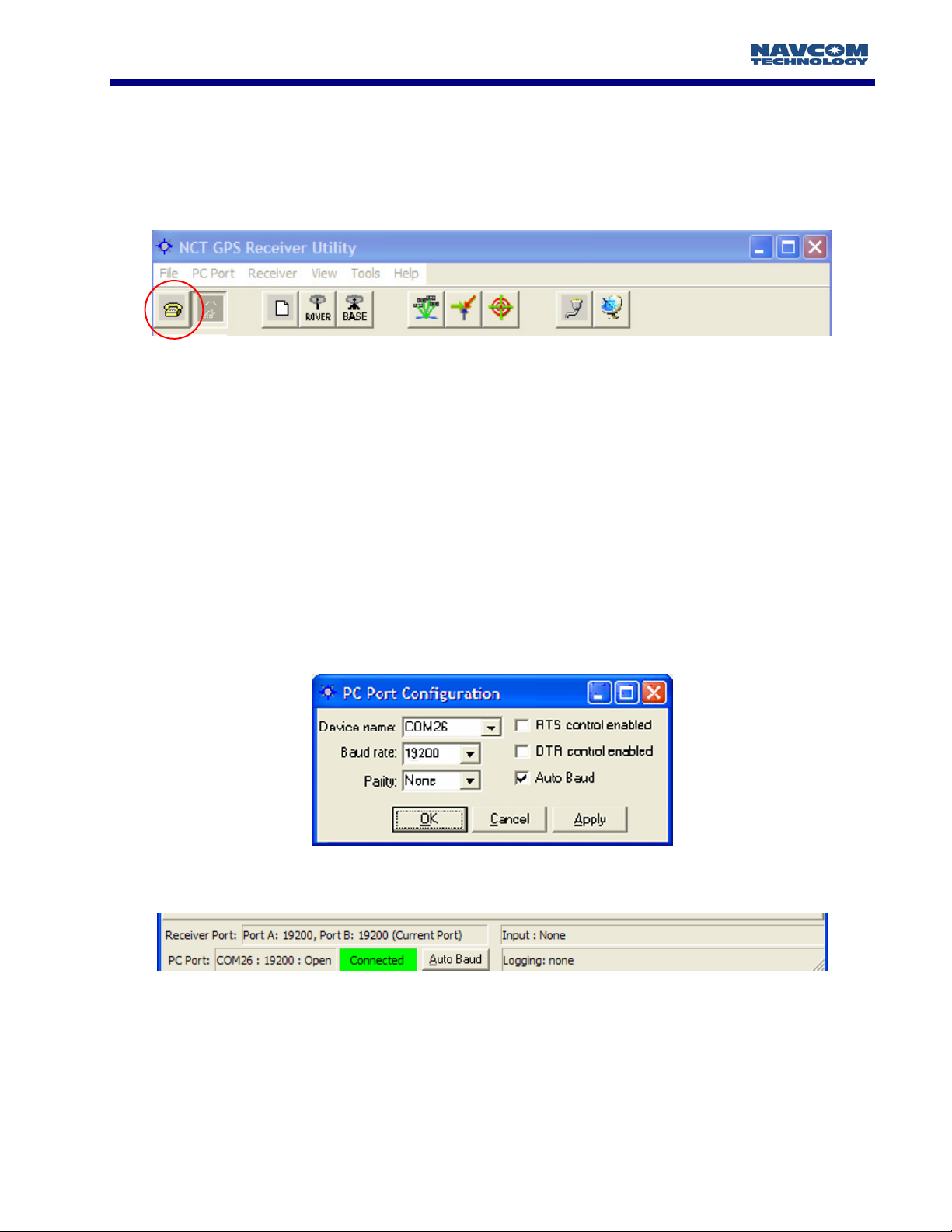
Figure 1: StarUtil Toolbar
A new window will appear as in Figure 2. StarUtil includes an Auto Baud Detect feature that will
allow for quick protocol connection between the PC, and the GPS receiver. You are also given an
opt-out if you choose to manually pick a baud rate. Check the Auto Baud box to initiate automatic
detection, uncheck the box to choose a baud rate from the pop-up window.
StarUtil automatically reads the available serial ports (i.e. RS-232 ports) from the Windows
®
registry,
and displays them in a pop-up window. Choose the Com Port that you will be using to control the
GPS receiver. Typically RTS/DTR and Parity options will remain in the default states unless your
system requires that these options be changed. Once the connection is established the PC COM
Port Status Bar at the bottom of the main StarUtil window will provide connection information as
shown in Figure 3. Information provided is PC COM port baud rate, GPS receiver port baud rate for
both Com Ports, Data Logging Status, and any Input activity. There is also an Auto Baud button,
which only becomes active after the initial connection has been established.
Figure 2: PC Port Configuration
Figure 3: PC Port Status Bar
2 - 9
Page 11
STARUTIL User Guide Rev. E
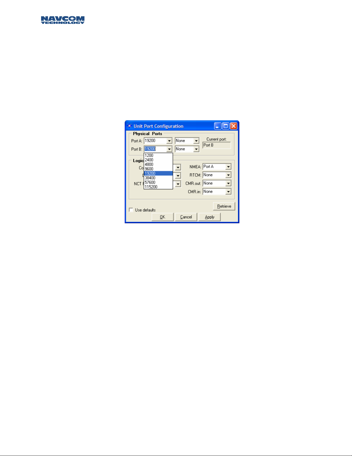
Now that PC Port Configuration has been established, the receiver must have its logical ports setup
to meet the specific requirements of the application. At this point you may choose to change the
Control Port to Com 1, elect an output port for NMEA, or an input port for the correction
information being received from an external source. The Unit Port Configuration screen can be
reached by pressing the Ports icon on the Toolbar, or from the Menu Bar pressing
RECEIVER\SETUP\PORTS. Figure 4 shows a typical Unit Port Configuration used for outputting
NMEA data via the Data Port [Port A/Com 1], controlling the receiver via Com 2 [Port B], and
receiving RTK corrections via the *internal radio. The Physical Ports area of Figure 4 displays the
baud rate, and parity at which the port communicates to the Controller Solution.
*
Internal radio option available on the RT-3010 & RT-3020 models only.
Figure 4: Unit Port Configuration
The Default Settings of the Physical Ports is set to 19200. The baud rate can be changed by simply
clicking on the pull-down menu for port A and B and selecting any of the predetermined baud rates
as shown in Figure 4.
The default logical physical mapping places the Control in the Current Port B, and Data, & NMEA,
in the Non-Current Port A. The logical physical mapping of ports can be changed by clicking on any
port and the pull-down menu shown in Figure 4. Logically, there are six ports and physically there
are two, Port A [Com1], and B [Com 2]. The six logical ports are Control, Data, NCT RTK, NMEA,
RTCM, and CMR as shown in Figure 4. Control and NCT RTK are very similar and work with
proprietary messages. The RTCM port receives differential corrections as a rover, and sends out
RTCM 104 corrections if the receiver has been set up as a base station; the CMR port operates in
similar fashion. The NMEA port communicates messages using a protocol for communications
between marine instrumentation. This interface permits flexibility in communication and control of
the various message streams.
The “Apply” button sends the changes to the receiver, and will store the values in NVRam for
recovery after a power cycle. The “Retrieve” button will send a request to the
information stored in NV-Ram pertinent to this particular display. These two buttons operate as
described for each window in which they appear. Checking the Use Defaults box will apply the
factory default configuration for both Physical and Logical Ports.
receiver for the
2 – 10
Page 12
STARUTIL User Guide Rev. E
Chapter 3 Navigation & Data Output Configuration
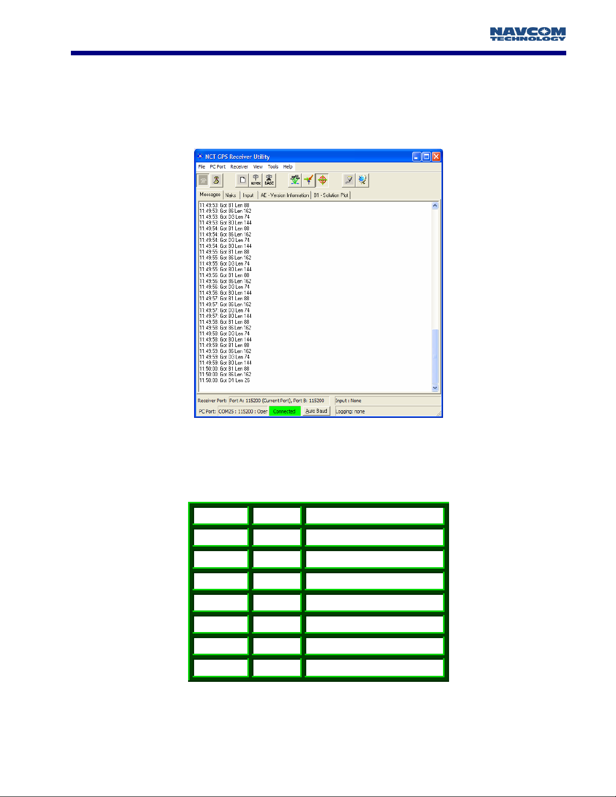
At this point the GPS receiver is ready to be configured for your specific application requirements.
The GPS receiver is factory defaulted to output 7 NCT binary messages via the factory default
control port Com 2. After successfully establishing communications with the receiver, you should
see NCT messages scrolling up in the Messages tab of StarUtil’s main window as seen in Figure 5.
Figure 5: StarUtil Main GUI Window
The messages chosen afford the user the ability to get started viewing, collecting, and analyzing
GPS receiver data immediately. The default messages output from the receiver are shown in Table 1.
Message Rate Description
44
81
86
B0
B1
On Change
On Change
On Change
On Change
On Change
Packed
Almanac
Packed
Ephemeris
Channel
Status
Raw Measurement Data
PVT
Block
A0
AE
On Change
600 Sec
Alerts
Software Versions
Table 1: NCT Binary Default Output Messages
3 - 11
Page 13
STARUTIL User Guide Rev. E
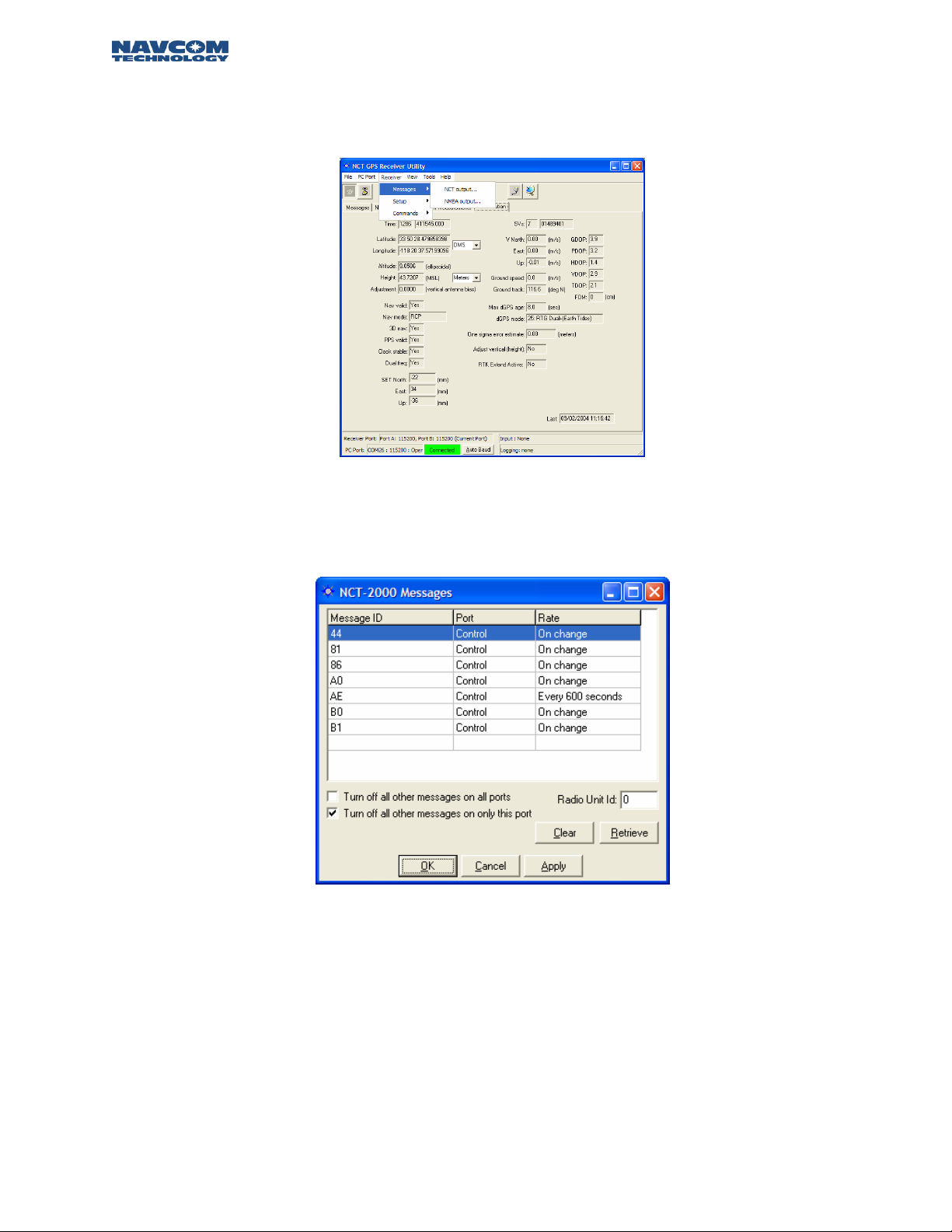
The user is allowed to add or delete NCT and/or NMEA message from each format’s output list. This
is established by clicking on RECEIVER\MESSAGES\NCT OUTPUT from the StarUtil Menu bar as
shown in Figure 6.
Figure 6: Message Output List Control
After choosing the message output type [in this case NCT Binary] the window shown in Figure 7 will
appear allowing you to add or delete any of the NCT Binary messages, and schedule the frequency
of their output.
Figure 7: NCT-2100/NCT-2000 Message List
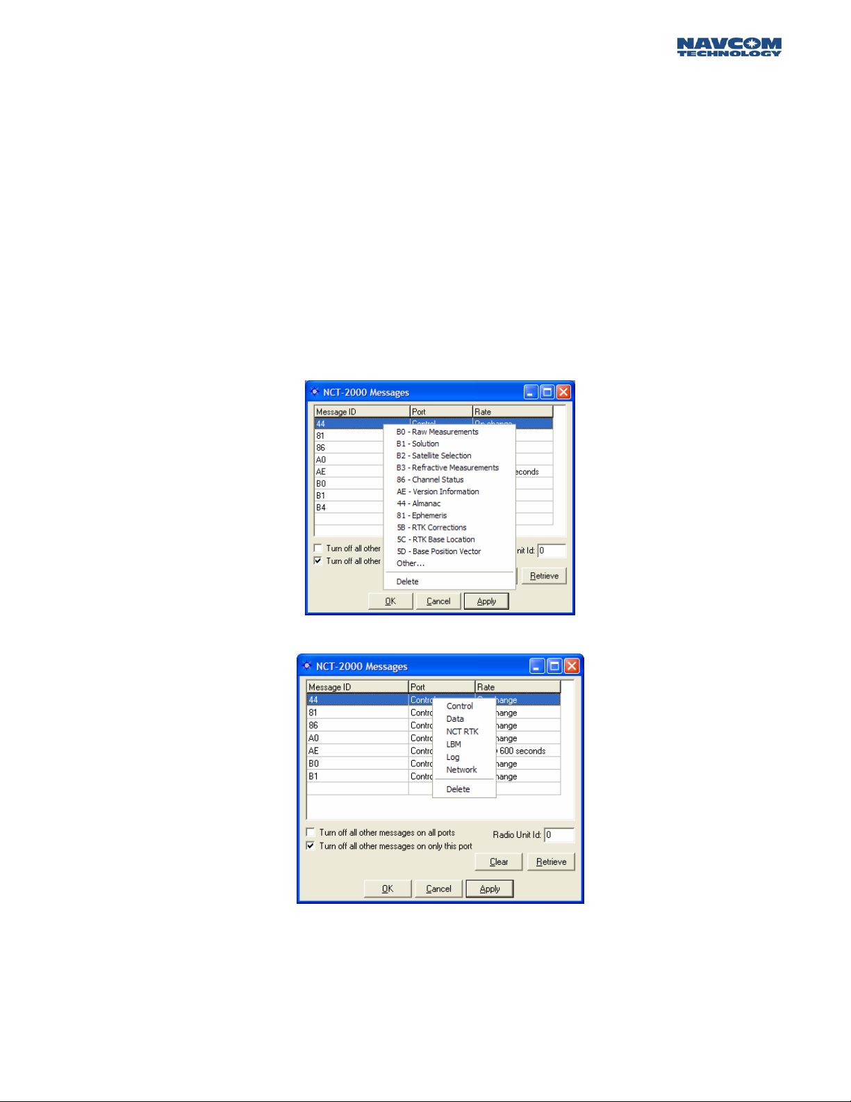
To add messages to the NCT Output List right click in the blank Message ID cell. A list of commonly
used messages will appear; see Figure 8. Click on the message of your choice and it will be added to
the list. Right click on the Port cell to choose where the message will be sent; see Figure 9. Right
click on the Rate cell and you will be given several options as to the frequency of the output for the
message; see Figure 10. Pressing the “Apply” button will send the new list, and scheduling
information to the receiver. If a message you wish to schedule is not in the preset list, choose
“Other” and you will be given the opportunity to manually enter the hex ID of the message you
need.
3 – 12
Page 14
STARUTIL User Guide Rev. E
There are two check boxes that allow the end user to quickly delete all messages in the NCT2100/NCT-2000 Message List. By checking the “Turn Off All Other Messages On All Ports” box, and
clicking Apply, all NCT-2100/NCT-2000 messages previously scheduled for output on Control, Data,
or NCT RTK will be deleted from the message list and data output will stop.
By checking the “Turn Off All Other Messages On Only This Port” box, and clicking Apply, all NCT2100/NCT-2000 messages previously scheduled for output on Control will be deleted from the
message list and data output on the Control Port will stop, leaving any data scheduled for output on
the Data or NCT RTK port to flow freely as scheduled.
Pressing the Clear button will clear the NCT-2100/NCT-2000 messages list on the screen, but will
not affect the output of the receiver.
Deleting a message can be accomplished in one of two ways, either click on the message and press
the Delete key on the keyboard, or Right click on the message, and choose Delete from the popup
menu; see Figure 8.
Figure 8: NCT Message Choice Added to Output List
Figure 9: NCT Message Logging Port Choice
3 - 13
Page 15
STARUTIL User Guide Rev. E
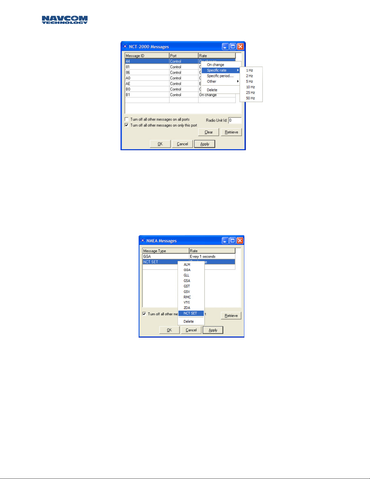
Figure 10: NCT Message Output Rate Choice
The NCT messages scheduled should appear scrolling up in the Messages tab of the main StarUtil
window as seen in Figure 5, StarUtil Main GUI Window.
NMEA messages and output rates are chosen in similar fashion via the RECEIVER\NMEA\MESSAGES
menu choice. Additionally, the end user can now have a NCT Proprietary NMEA Type string output
from the NMEA port by choosing NCT SET from the NMEA messages list as shown in Figure 11,
which will provide Solid Earth Tide (SET) correction information.
Figure 11: NMEA Messages Scheduling Window
3 – 14
Page 16
STARUTIL User Guide Rev. E
Solid Earth Tide (SET) Implementation
In order to have the SET correction information applied to the position solution there are several
caveats that must be engaged.
1. Navigation MUST be valid.
2. SET Software Option is Enabled.
3. Navigation Mode is set to RTG from the Rover / Tracking & Navigation Setup, Figure 15.
4. SET are applied (“USE”) from the Rover / Tracking & Navigation Setup, Figure 15.
5. SET correctors are valid (minimum of 1 run of the SET algorithm).
Once the criteria above have been met, the SET corrections will be applied to the position solution,
and displayed as North, East, and Up corrections in millimeters on the B1 Solution Window. It will
also be output on the NMEA port. A sample SET message appears in Figure 12, a detailed
description of the NMEA Type message structure can be found in Appendix A Table A1.
$PNCTSET,161625.00,-0.008,0.003,-0.099,,,,,,*47
Figure 12: NCT SET NMEA Sample
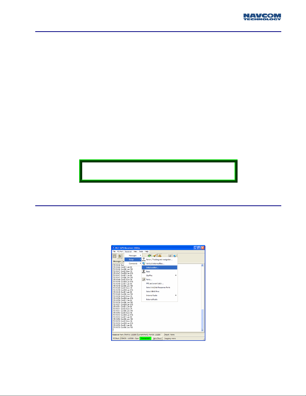
Receiver Initial Position Setup
Depending on your Latitude & Longitude, you may be required to enter an initial position in order
to start navigating in the shortest period of time. This is accomplished by clicking on the menu bar
RECEIVER\SETUP\INITIAL POSITION as shown in Figure 13.
Figure 13: Initial Position Location
3 - 15
Page 17
STARUTIL User Guide Rev. E
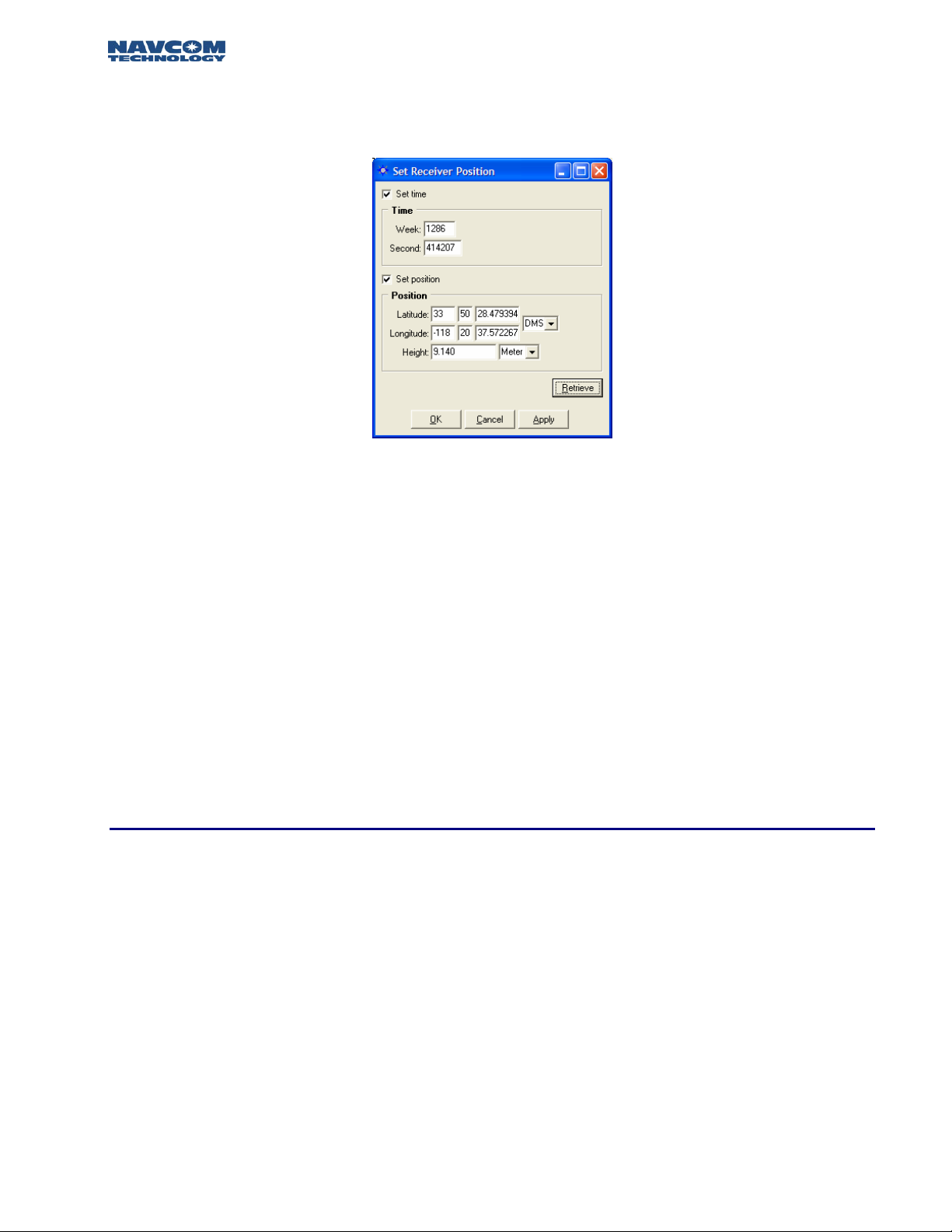
The Set Receiver Position screen will appear as shown in Figure 14. The Receiver Position Menu is
comprised of Message Block 0x46 Initial Time and Position.
Figure 14: Set Receiver Position
Click the Set Time box to change the elapsed time since the beginning of the week in seconds if
known. It is not mandatory to set this field since once a satellite is tracked GPS Week Number, and
GPS Week Seconds will automatically update. After the receiver starts tracking satellites, time cannot
be set since the time from the satellite is assumed to be more accurate.
Click the Set Position box in order to change the initial position the receiver will use to track
satellites. Typically a position within 500km will be close enough to pickup satellites and acquire
almanac and ephemeris information. The position can be entered in DDMMSS format, or by use of
the pull down window DDMM format. Similarly the ellipsoidal height can be entered in meters or
feet.
Once the position has been entered, press the “Apply” button and the receiver will use the newly
entered position to locate its first satellite and update almanac and ephemeris information.
Collection of a new almanac requires 12.5 uninterrupted minutes of continuous satellite tracking.
Rover / Navigation & Tracking Setup
Typically the receiver will come from the factory setup as a GPS autonomous rover. Depending on
the options purchased, you may set the receiver up to accept dGPS/RTK/RTG corrections from an
external source. Figure 15 shows the Navigation & Tracking Setup window and the various options
available to the user as a rover. This menu comprises message blocks 0x47 (SV Tracking Control),
and 0x49 (Solution Control). Access this window by clicking RECEIVER/SETUP/ROVER-TRACKING &
NAVIGATION, or click the Rover icon on the main StarUtil toolbar.
3 – 16
Page 18
STARUTIL User Guide Rev. E
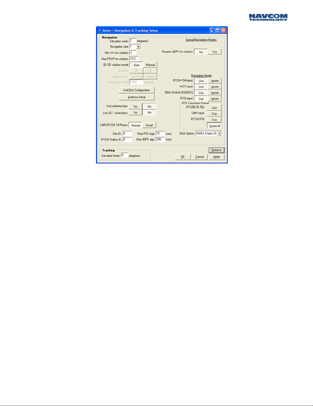
Figure 15: Rover Navigation & Tracking Parameters Setup
The Navigation Elevation Mask selects the elevation angle the receiver starts processing GPS data
from the satellites. The default is set to 7 degrees because GPS measurements of satellites at lower
elevation tend to deteriorate accuracy.
The Navigation Rate is the number of Navigation Solutions per second. The default rate is 1 Hz and
can be increased up to 25 hz as a purchased option.
The Navigation Rate of the 0xB1 message is changed here and NOT on the NCT Message
Output list. Attempting to change the Nav Rate in the NCT Message Output list will delete the
0xB1 message from the output list.
The minimum amount of satellites required for navigation is a user input value =>3. The default is 3
and denotes a 2 dimensional navigation solution. If height solution is needed, an additional satellite
must be manually entered bringing the total to 4. Obviously, the larger the number of satellites
required for navigation, yields a longer period of time before position output
The default setting for Max PDOP is 10. The quality of GPS data is dependent on the geometry
between the receiver and satellites; this includes the number of satellites that can be "seen" by the
receiver and the angle between the receiver and satellites. A satellite near the horizon usually
provides a lower quality signal because of greater atmospheric interference and the increased
likelihood of the signal reflecting from surface features, this is known as "multipath" error. The effect
of geometry on GPS quality is measured by PDOP (position dilution of precision). PDOP is the
overall measure of the precision obtainable with a given satellite geometry. For example, a PDOP of
4 or less yields excellent precision, a PDOP between 5 and 7 is acceptable and a PDOP of 7 or more
is considered poor.
A 2D solution is an altitude hold mode. This typically indicates that the receiver is navigating using
only 3 satellites, and the altitude component is a manually entered valued. This altitude value used
can either be the value entered or the last computed altitude. A 3D solution typically indicates that
the receiver is navigating using 4 or more satellites. When the 2D/3D button is in the Auto mode,
3 - 17
Page 19

STARUTIL User Guide Rev. E
the receiver will transition from a 2D [3 satellite] to a 3D [4 satellite] navigation mode automatically,
and use the user selected choice of a manually entered height or the last valid computed height
measurement recorded to achieve a 3D navigation state.
The Unit Port Configuration button will bring up the window displayed in Figure 4. The operation of
this window is described in detail in the Establishing Communications section of this manual.
The Antenna Setup button will bring up the window shown in Figure 16. This feature allows you to
enter antenna specific adjustments.
Figure 16: Vertical Antenna Bias
After entering the Antenna Bias information, you are given the option of whether or not to apply the
biases to the measurements by pressing the Yes/No button adjacent to “Use Antenna Bias”.
In a small number of instances, there may be a requirement where the RTCM phase corrections are
received in an “inverted” state. StarUtil will correct the sign of the corrections automatically so they
may be applied without prejudice. This will be accomplished if the Invert button (see Figure 15)
adjacent to RTCM 18 Phase is set to Inverted.
The Site ID field (see Figure 15) defaults to 0, which indicates that the receiver will accept RTK
corrections from any base receiver that is transmitting. In order to use the RTK corrections from a
specific base receiver, the Site ID field in the base and rover must be the same value. The RTCM Site
ID works in similar fashion for dGPS.
Max dGPS Age and Max RTK age is a user input integer that relates to the maximum amount of
time in seconds the received correction will be used in case of an outage or drop in the reception of
corrections from the base.
The “Require dGPS for Solution” button allows the user to determine whether or not a position
solution will be output using dGPS as a caveat. This feature is useful when only dGPS corrected
position solutions are desired. The default position is set to No which indicates that all computed
position solutions will be output whether differentially corrected or not.
The Navigation Mode section is where the user will Use/Ignore a specific type of dGPS correction
data if available, while the RTK Correction Format section is where the user will Use/Ignore the type
of RTK corrections that will be applied to the navigation solution.
3 – 18
Page 20

STARUTIL User Guide Rev. E
The Tracking Elevation Mask selects the elevation angle the receiver starts tracking satellites. The
default is set to 0 degrees and can be changed by the operator.
The GGA Option provides the end user the ability to output a GGA message that strictly conforms
to the NMEA Standard v3.01 by choosing NMEA Station ID, or by choosing the NCT Station ID the
end user can populate the Differential Reference Station ID field with values that will provide
information pertaining to the Navigation Mode, correction signal, and correction data stream that
has been applied to the position information in the GGA message. See Appendix B, Table B1 for the
NCT Station ID matrix.
NCT Operating Parameter Displays
The StarUtil program provides a list of 22 NCT binary messages can be viewed in ASCII format (see
Figure 17), two of which can also be viewed in a graphical plot format. By clicking on View from the
main StarUtil window, you can select a desired NCT binary message and have it displayed in a
tabbed inset window of the main StarUtil window, as shown in Figure 19. This tabbed inset window
can be dragged to another area of your Windows
StarUtil window as shown in Figure 19.
Any independently operating window may be closed withou affecting the main StarUtil
program, however if the main StarUtil program is closed, all open windows will be terminated.
®
OS desktop and act independently of the main
t
In order for the information in the View windows to update, the associated message must be
enabled in the NCT-2100/NCT-2000 Message List, see Figure 7. The rate at which the View window
data is updated will be at the output data rate chosen in the NCT-2100/NCT-2000 Message List,
with the exception of the 0xB1 message. The data rate for the 0xB1 message is controlled through
the Rover Navigation &Tracking window; see Figure 15.
Figure 17: View NCT in ASCII Choice
3 - 19
Page 21

STARUTIL User Guide Rev. E
Figure 18: View of Tabbed NCT Messages in ASCII
Figure 19: View of Tabbed 0xB1 in ASCII; Independent Window
3 – 20
Page 22

STARUTIL User Guide Rev. E
Once the receiver is setup and tracking satellites, the signal characteristics of the satellites being
tracked can be viewed by navigating to VIEW/86 Channel Status – E1 Satellite Failure Details. The
window as shown in Figure 20 will appear.
2
3
6-15
1
4
5
16
Figure 20: View of Receiver Channel Status
The Channel Status window provides the user with a powerful tool, which allows for instantaneous
diagnosis of signal quality, and performance. The number of channels displayed in the 0x86 window
is dependant on the model of GPS engine sensed by StarUtil. While the NCT-2100 will display 14
dual frequency channels as shown in Figure 20 (12 GPS + 2 WAAS/EGNOS), the NCT-2000 will
display 12 channels of dual frequency satellite information (10 GPS + 2 WAAS/EGNOS). Below is a
description of the various information found on this screen.
17
1. Time: Top field indicates the GPS Week number; bottom field indicates GPS Seconds into the
week.
2. SVs Visible: The number of GPS satellites that should be visible according to the current
almanac stored in NVRam.
3. PDOP: Position Dilution of Presicion value, which should typically be between 2 and 5 during
periods of optimal performance.
4. Tracked: The number of GPS satellites currently being tracked by the receiver.
5. ellites currently being used
Used: Of the number being tracked, the actual number of GPS sat
in the navigation filters to determine position, velocity, and time.
6.
Ch: The channel number of the receiver. The number of channels noted is dependant on the
type of GPS receiver. The NCT-2100 will display GPS satellites on channels 1 – 12, and
WAAS/EGNOS satellites on channels 13 and 14, while The NCT-2000 will
on channels 1 – 10, and WAAS/EGNOS satellites on channels 11 and 12.
3 - 19
display GPS satellites
Page 23

STARUTIL User Guide Rev. E
7. SV: The GPS satellite number assigned to that particular channel.
State: The NCT proprietary satellite tracking value assigned to each satellite tracked that
8.
indicates the type of tracking mode the satellite is in.
with 255 being optimal dual frequency performnance. Any value other than 255 is considered
to be less than optimal performance by the receiver.
This value ranges between 0 and 255,
9. Elevation: The vertical angle of the satellite off the horizon ranging from 0 degrees to a zen
of 90 degrees.
10. Azimuth: The horizontal angle of the satellite in reference to North ranging from 0 (3
degrees to 359 degrees.
60º)
11. CA: The L1 signal-to-noise value, which will vary depending on satellite State. Optimal
performance range for L1 C/N0 is 46dB to 52dB, although higher and lower values can
noted.
be
12. P2: The L2 signal-to-noise value, which will vary depending on satellite State. Optimal
performance range for L2 C/N0 is 42dB to 48dB, although higher and lower values can be
noted.
13. IODC: Issue of Data Clock, which indicates the issue number of the data as provided from
the GPS satellite in accordance with ICD-200C.
dGPS Age: The age of the current aided navigation correction. This value will change
14.
depending on the correction source, and the correction interval.
15. Status: This is the channel tracking status of each individual channel.
ith
16. Satellite Failure: Populated with information determining why a particular satellite is having
difficulty being tracked or providing reliable position information.
17. Last: Shows the MM:DD:YY and HH:MM:SS of the last 0x86 window update.
3 – 20
Page 24

STARUTIL User Guide Rev. E
Chapter 4 Base Station Setup
Throughout the first three chapters, your receiver has been navigating as an autonomous state
rover. Below are several examples of how to set the receiver up to transmit RTK Extend/RTK/dGPS
corrections via internal and external radios.
RTK Extend Base Station operation can only be accomplished with a StarFire™ equipped receiver
that has the software option enabled.
RTK/dGPS Base Using Internal Radio
Initially the user must decide several key factors:
¾ The Base Station Network ID; which is used as a unique Base Station identifier assuring
that only corrections from said base are used if there are multiple base stations setup in
radio range of the rover on the same frequency.
¾ The Site ID [0-1023]; which is used as a check for which Base Station site the receiver will
process corrections from. This can be used when it is desirable to have multiple Base
Station setups on a single Network ID, but with a separate Site ID for each base receiver.
This ID MUST match the Rover ID!
¾ Power level used.
¾ Enable Master (Base) mode.
The Base Station Network ID is a unique value, which is “pinged” from one radio to another. Once a
matching connection is established between the radio pairs, any data received will be processed and
passed on. The Base Station Network ID can be located from the main StarUtil window by clicking
RECEIVER\SETUP\INTERNAL RADIO\NETWORK CONFIGURATION, as seen in Figure 21.
Figure 21: Network Configuration Location
4 - 21
Page 25

STARUTIL User Guide Rev. E
Figure 22 shows the window that will appear. The Network ID can be set to any value as low as 1
and as high as 65535. The rover receiver must also be set to this value. The Local Radio/Unit ID is
the serial number of the NCT2100/NCT-2000 GPS Engine. Clicking “Apply” sends the changes to
the receiver, and “Retrieve” confirms those changes, thus ensuring a unique hardware identifier.
Figure 22: Network Configuration
Press the Base Icon on the StarUtil main window, and Base Configuration window shown in Figure
23 will appear. This window is where the majority of controls are that will enable the receiver to
operate as a Base Station.
Figure 23: Base Configuration Window
4 – 22
Page 26

STARUTIL User Guide Rev. E
In the Define Correction Type area of Figure 23, you will choose the corrections that are required for
output, the Correction Output Rate, and the Base Position Output Rate. In this instance you will
choose Proprietary RTK. Figure 24 shows the available correction types the receiver can transmit.
Figure 24: Output Correction Types
In the RTK Base Control area of this window you will choose an Elevation Mask, and a Base Station
Site ID. The Unit Port Configuration button in this screen brings up the window described in
Chapter 2 Figure 4 set to the default parameters, and the Antenna Setup button brings up the
window described in Chapter 3 Figure 16.
The Setup Base Location area of the Base Configuration window allows the user to manually enter a
Base position, for which corrections will be generated, or have the receiver automatically generate a
position relative to phase positions collected and averaged over a period of time. Figure 25 & 26
show what this area will look like when “User Input” or “Self Survey” is enabled.
Figure 25: Setup Base Location; User Input
Figure 26: Setup Base Location; Self-Survey
The user must enter a Base Location through one of the modes described before output of valid
corrections can commence.
4 - 23
Page 27

STARUTIL User Guide Rev. E
Since in this example we are taking advantage of the on board radio, we need to setup the power
output, and set up the receiver to the Master (Base) mode of operation. Clicking on
RECEIVER\SETUP\INTERNAL RADIO\SETTINGS accesses both of these commands, as shown in
Figure 27.
Figure 27: Internal Radio Settings Location
After choosing Settings, the window in Figure 28 will appear allowing the user to change a variety
of internal radio parameters. Typically it is unnecessary to change 99% of these options. There are
only two that are of major concern at this point, Operation Mode and Power Level.
Figure 28: Radio Configuration; Operation Mode
In order to change the Operation Mode from Slave (Rover Default) to Master (Base), select Master in
the Mode pull down menu as seen in Figure 28. Click on the Power Level Tab in this window, and
the display will resemble Figure 29. Choose the appropriate power level required to reach the Rover
receiver.
Please note that the maximum allowable power setting is controlled by NavCom Technology,
Inc. as per United States of America FCC regulations.
4 – 24
Page 28

STARUTIL User Guide Rev. E
Figure 29: Radio Configuration; Power Level
Now that the unit is configured to output the corrections, the output port for those corrections
must be chosen. In this example we are utilizing the internal radio, so we must choose the NCT RTK
port as Port Radio as shown in Figure 30. However, the corrections can be simultaneously sent to
any of the logical ports, and also the internal MMC Memory Module for logging.
Figure 30: Corrections Output to Internal Radio Port Configuration
RTCM, CMR+, and CMR Base Stations are setup in the same manner as the Proprietary RTK output.
After choosing your dGPS format, the appropriate areas of the Base Configuration window will
become active. As with the example above, provide the necessary information, and click “Apply” or
“OK” to have your changes preserved in the receiver. In the Unit Port Configuration window in
Figure 30, choose the port the dGPS corrections will be output to.
RTK Extend/RTK/dGPS Base Using External Radio
Setup the external radio in compliance with the documentation received with the radio. You should
know the baud rate of the radio, and the transmission protocols before connecting the GPS
receiver‘s data output to the radio.
4 - 25
Page 29

STARUTIL User Guide Rev. E
Press the Base Icon on the StarUtil main window, and Figure 23 will appear. This is the Base
Configuration window, where the majority of controls are that will enable the receiver to operate as
a Base Station.
In the Define Correction Type area of Figure 23, you will choose the corrections that are required for
output, the Correction Output Rate, and the Base Position Output Rate. In this instance you will
choose Proprietary RTK. Figure 24 shows the available correction types the receiver can output.
In the RTK Base Control area of this window you will choose an Elevation Mask, and a Base Station
Site ID. The Unit Port Configuration button brings up the window described in Chapter 2 Figure 4,
and Antenna Setup brings up the window described in Chapter 3 Figure 16. The Unit Port
Configuration window may open set to the default parameters. At this point you should direct the
NCT RTK corrections to an external port for output. If the NCT RTK port is not set to A or B [any
port other than the Control Port, Port Radio, or NONE], change the NCT RTK port to the opposite
of the Control Port, i.e. Control is B (default) then NCT RTK will be A, and press “Apply”. Connect
the output port cable to the external radio; you should now have corrections sent out over the
external radio link.
The Setup Base Location area of the Base Configuration window allows the user to manually enter a
Base position, for which corrections will be generated, or have the receiver automatically generate a
position relative to phase positions collected and averaged over a period of time. Figure 25 & 26
shows what this area will look like when User Input or Self Survey is enabled. The user must enter a
Base Location through one of the modes described so the output of valid corrections can
commence.
RTCM, CMR+, and CMR Base Stations are setup in the same manner as the Proprietary RTK output.
After choosing your dGPS format, the appropriate areas of the Base Configuration window will
become active. As with the example above, provide the necessary information, and click “Apply” or
“OK” to have your changes preserved in the receiver. An additional step is required to output these
formats; in the Unit Port Configuration window in Figure 30, the user must choose the port the
dGPS corrections will be output to.
RTK Extend Users:
An additional message must be transmitted over your external radio link in order to enable the RTK
Extend feature in the Rover. Follow the procedure in Chapter 3 Navigation & Data Output
Configuration, to enable the 0x5D message. The
5D message rate should be “On Change”, and the
Output port will be the same as is configured for the 0x5B and 0x5C messages. Figures 6 – 10 detail
just how to accomplish this. After completing all actions, your NCT Messages window will appear as
shown in Figure 31.
Figure 31: RTK Base Message Output List
4 – 26
Page 30

STARUTIL User Guide Rev. E
Chapter 5 RTK Extend / RTK / dGPS / SBAS Rover Setup
Depending on the options you have purchased, the receiver can use any one of the various
correction sources available as detailed in the Rover Operating Mode section of this manual. Below
are several examples of how to set the rover receiver up to accept RTK/dGPS corrections:
RTK/dGPS Rover Internal Radio Setup
The internal radios for the Rover are setup similarly to the Base setup, except for a few Rover specific
choices that are required. All of the same menu items used to configure the Base Radio will be used
to configure the Rover.
Initially the user must decide several key factors:
¾ The Base Station Network ID; which is used as a unique Base Station identifier assuring
that only corrections from said base are used if there are multiple base stations setup in
radio range of the rover on the same frequency.
¾ The Site ID [0-1023]; which is used as a check for which Base Station site the receiver will
process corrections from. This can be used when it is desirable to have multiple Base
Station setups on a single Network ID, but with a separate Site ID for each base receiver.
A “0” entered in this field denotes that any Base Station corrections received on the
Network ID chosen will be used.
This ID MUST match the Base ID!
¾ Power level used.
¾ Enable Slave (Rover) mode.
The Rover Network ID is a unique value, which is “pinged” from one radio to another. Once a
matching connection is established between the radio pairs, any data received will be processed.
The Rover Network ID can be located from the main StarUtil window by clicking
RECEIVER\SETUP\INTERNAL RADIO\NETWORK CONFIGURATION, as seen in Figure 21.
After choosing Settings, the window in Figure 28 will appear allowing the user to change a variety
of internal radio parameters. Typically it is unnecessary to change 99% of these options. There are
only two that are of major concern at this point, Operation Mode and Power Level.
Change the Operation Mode to “Slave” (Rover) as seen in Figure 28. Click on the Power Level Tab
in this window, and the display will resemble Figure 29. Choose the appropriate power level
required; typically this will match the Base power level.
NCT RTK Extend Input
This example assumes the receiver has been setup in compliance with Chapters 2 & 3, and a
correction source has been established in compliance with Chapter 4.
RTK Extend is a feature that allows your RTK-optioned StarFire™ receiver to coast on a StarFire™
solution maintaining centimeter level integrity. When the RTK link becomes unstable the mode
transitions smoothly to RTK Extend rather than dropping out of RTK and reverting to a multi-meter
level position fixes. This feature requires that the RTK option be purchased for the StarFire™ receiver
5 - 27
Page 31

STARUTIL User Guide Rev. E
Base & Rover pair for optimal performance, and also requires an external RTK link be established.
RTK Extend is only available in NavCom Technology receivers that are StarFire™ capable. To learn
more about RTK Extend follow this link:
To enable RTK Extend in the Rover receiver, go to the Rover Navigation & Tracking window shown
in Figure 15; in the RTK Corrections Format area click the “USE” button adjacent to RTK (5B, 5C,
5E). Then click the “USE” button adjacent to RTG Input. Click “Apply” and then “Retrieve” to ensure
your choices have been saved at the receiver.
Ensure that an input port for your RTK Extend corrections has been established in the Unit Ports
Configuration window as shown in Figure 30.
Once the corrections have been successfully received and applied, the resulting RTK Extend
Navigation indicators can be viewed in the dGPS Mode area of the B1 Solution display shown in
Figure 18.
http://www.navcomtech.com/products/rtkextend.cfm
NCT RTK Input
This example assumes the receiver has been setup in compliance with Chapters 2 & 3, and a
correction source has been established in compliance with Chapter 4.
Go to the Rover Navigation & Tracking window shown in Figure 15; in the RTK Corrections Format
area click the “USE” button adjacent to RTK (5B, 5C, 5E). Click “Apply” and then “Retrieve” to
ensure your choices have been saved at the receiver.
Ensure that an input port for your corrections has been established in the Unit Ports Configuration
window as shown in Figure 30.
Once the corrections have been successfully received and applied, the resulting RTK Navigation
indicators can be viewed in the dGPS Mode area of the B1 Solution display shown in Figure 18.
RTCM RTK Input
This example assumes the receiver has been setup in compliance with Chapters 2 & 3, and a
correction source has been established in compliance with Chapter 4.
Go to the Rover Navigation & Tracking window shown in Figure 15; in the RTK Corrections Format
area click the “USE” button adjacent to RTCM RTK. Click “Apply” and then “Retrieve” to ensure
your choices have been saved at the receiver.
Ensure that an input port for your corrections has been established in the Unit Ports Configuration
window as shown in Figure 30.
Once the corrections have been successfully received and applied, the resulting RTK Navigation
indicators can be viewed in the dGPS Mode area of the B1 Solution display shown in Figure 18.
CMR+/CMR RTK Input
This example assumes the receiver has been setup in compliance with Chapters 2 & 3, and a
correction source has been established in compliance with Chapter 4.
5 – 28
Page 32

STARUTIL User Guide Rev. E
Go to the Rover Navigation & Tracking window shown in Figure 15; in the dGPS Corrections area
click the “USE” button adjacent to CMR Input.
corrections to be applied
at the receiver.
Ensure that an input port for your corrections has been established in the Unit Ports Configuration
window as shown in Figure 30.
Once the corrections have been successfully received and applied, the resulting RTK Navigation
indicators can be viewed in the dGPS Mode area of the B1 Solution display shown in Figure 18.
In all of the above examples if an external radio is used, connect the data cable from the GPS
. Click “Apply” and then “Retrieve” to ensure your choices have been saved
receiver’s Data Port to the data port of the radio Depending on the radio’s output port
configu ation, a null modem may be required.
r
Enabling CMR input will allow CMR+ or CMR
.
SBAS
StarFire
The StarFire™ corrections are automatically applied to the position solution when the “USE” button
adjacent to RTG Input or WCT Input is chosen in the Rover Navigation & Tracking window, see
Figure 15.
WAAS/EGNOS
The WAAS/EGNOS corrections are automatically applied to the measurements when the “USE”
button adjacent to WAAS/EGNOS is chosen in the Rover Navigation & Tracking window see Figure
15.
A new feature has been added that will allow the user to choose the L1 SBAS satellite PRN that
corrections will be received from, or allow the receiver to choose for you. The window in Figure 32
can be accessed by clicking RECEIVER\SETUP\SELECT SBAS PRNS.
Figure 32: L1 SBAS Selection Window
5 - 29
Page 33

STARUTIL User Guide Rev. E
Chapter 6 NMEA Setup and Output
The receiver has the ability to output 9 industry standard NMEA data strings, and 1 NCT Proprietary
NMEA type string. To view the available NMEA messages, and enable them for output go to the
main StarUtil menu bar and click on RECEIVER\MESSAGES\NMEA OUTPUT as shown in Figure 33
below.
Figure 33: NMEA Output Menu Location
Clicking on NMEA Output will bring up the NMEA Messages window seen in Figure 34. The
operation of this window is similar to that of the NCT Messages screen as messages can be enabled
for output, and scheduled at a user variable rate. However, the output port for NMEA is chosen from
the Unit Port Configuration window seen in Figure 30.
The NMEA messages GGA, RMC, & VTG follow the output of the Navigation Rate up to 10 HZ
max, when NMEA outpu rate “On Change” is selected for these messages. Click on the Rover
icon, and then choose a Navigation Rate from the pop-up window.
t
Receiver must be optioned
for multi-hertz Navigation Rate to ach eve multi-hertz NMEA outputi .
Figure 34: NMEA Message Choices & Data Rate
NMEA messages cannot be outpu on the same port that is u ed for Control. t s
6 - 30
Page 34

STARUTIL User Guide Rev. E
NMEA can be logged and/or viewed using the NMEA Viewer window, although any ASCII RS232
port viewer will suffice. This allows the user a convenient place to monitor the NMEA output. To get
to the NMEA Viewer window, from the main StarUtil menu click on TOOLS\NMEA VIEWER as
shown in Figure 35.
Figure 35: NMEA Viewer Menu Location
Figure 36 shows what a typical NMEA data output would look like in the viewer. The NMEA Viewer
contains a Browse button so data can be logged to any media device that can communicate with
the data port.
Figure 36: NMEA Viewer & Data Logging
A second instance of StarUtil must be run, and connected to the Data Port in order for the
NMEA Viewer to display the NMEA data messages.
6 – 31
Page 35

STARUTIL User Guide Rev. E
NMEA GGA Station ID Field 14
The NMEA GGA message field 14 is now user configurable and can display information that strictly
conforms to the NMEA 3.01 Standard or the receiver’s Navigation Mode. The Navigation Mode
information will be the same as contained in Word 22 of the binary B1 output message. A break
down of field 14 contents as it relates to the Navigation Mode information can be found in
Appendix B of this user guide. Information on the NMEA Standard can be found in the official
NMEA 3.01 Standard Manual.
To choose the contents of field 14 of the GGA message, click on the ROVER icon on the StarUtil icon
bar. The window shown in Figure 15 will appear. In the lower right portion of the window you will
see GGA Option as shown in Figure 37. NMEA Station ID conforms to the NMEA 3.01 Standard,
while NCT Station ID conforms to Appendix B of this user guide. Choose your option from the pull
down menu, and press “OK” or “Apply” to save your choice to the receiver’s memory.
The default option for this feature is to comp y with the NMEA 3.01 Standard, which is NMEA
l
Station ID.
Figure 37: NMEA GGA Field 14 Option
6 - 32
Page 36

STARUTIL User Guide Rev. E
Chapter 7 Data Logging
Data can be logged from either of the physical ports, or to the on board 64 Megabyte Memory
Module Card (MMC). This data can be used in a number of industry standard GPS data analysis
programs either in NCT Binary format, after being converted to RINEX format, or by using the
NMEA output.
External NCT Binary Logging
Once the receiver is setup and navigating to your specifications, go to the main StarUtil menu and
click FILE\LOG DATA TO FILE as shown in Figure 38.
Figure 38: NCT External Logging Menu Location
Once you click on this item, the window in Figure 39 will appear. This window not only allows for
immediate data logging, but also allows for automatic 24-hour data file splits.
Figure 39: External Logging Setup
7 - 33
Page 37

STARUTIL User Guide Rev. E
The Current Status area lets the user know if logging is enabled, if the scheduler [24-hour splits] is
enabled, and the path to the logging data.
Clicking the “Apply” button the Logging Schedule area will enable the scheduling of the 24-hour
data file splits. These file splits restart at 00:00:00 GMT, and create a new folder name at each 24hour period.
A logging name must be provided before logging can commence, NCT.dat is a default name that
will appear whenever logging is initiated.
Logging cannot start without a Directory path being assigned. StarUtil will create a folder under the
Directory path chosen named in the yymmdd format; i.e. if your Directory path chosen is
d:\NavComWorking\Data, the true path to your data will be d:\NavComWorking\Data\yymmdd.
The activities area is to inform the user of what processes have taken place in the logging area.
Almanac & Ephemeris data currently in the receiver’s NVRam is automatically downloaded to
the data file when logging is initiated, regardless of whether the Almanac & Ephemeris messages
are scheduled in the NCT Output Messages list shown in Figure 7.
Internal NCT Binary Logging
Logging internally is accomplished through an onboard 64MB Memory Module Card (MMC).
Scheduling of NCT binary message to be logged is done through the NCT-2100/NCT-2000
Message window as shown in Figure 7. Since StarUtil’s GUI is driven from the NCT Messages list, it
is recommended that a separate instance of each message required for internal logging be enable.
Choose the messages for internal logging as shown in Figure 40. Alternately, pressing the “Schedule
Default Messages” button shown in Figure 42 will add a set of commonly used messages to the
NCT Output list directed to the LOG Port as shown in Figure 40. In order to log data internally, the
LOG port must be chosen in the Ports field for any given message as shown in Figure 40. A default
data rate of On Change or 1 Hz will be assigned.
Figure 40: MMC Internal Logging Port Selection
Although the Data Rate field for the LOG Port will indicate a choice o multi-hertz rates, the
f
internal MMC logging is limited to On Change & 1 Hz data rates.
7 – 34
Page 38

STARUTIL User Guide Rev. E
Once the messages have been scheduled to the Log Port, open up the MMC window by going to
the main StarUtil menu and clicking on TOOLS\MMC INTERNAL DATA LOGGING as shown in
Figure 41.
Figure 41: MMC Internal Logging Control Location
This will bring up the window in Figure 42. From here you will be able to initiate internal logging,
download, format the memory module, sort the files directory, delete files, and more. A status bar at
the bottom of this window allows the user to see how much space has been used and the total
memory size available. The number of files on the disk, and how much space they occupy, and the
date & clock information are also here.
Figure 42: MMC Internal Data Logging
If internal logging is enabled and power is turned off, internal logging will resume on power up
creating a new filename with an extension of .001. A new file will be generated and the extension
value incremented for each power off-on cycle, if logging has not manually been stopped by the
end user.
With this feature the user can initiate the logging parameters at the office, and start the logging
process. Then power off the receiver and move it to a remote location. As soon as power is applied
to the receiver and it initializes, internal data logging will begin. This allows the user to collect data
without having an external data collection device connected.
7 - 35
Page 39

STARUTIL User Guide Rev. E
If you have never used the internal logging feature, the MMC must be formatted. Click on the More
button shown in Figure 42, and then click the Format MMC menu item as shown in Figure 43.
Figure 43: More Button Choices
A Warning window will appear giving you the opportunity to opt-out of the formatting process.
Pressing Yes will bring up the Format MMC Label window shown in Figure 44 asking to label the
MMC; a suggestion would be to enter the serial number of your GPS receiver here although any
name or none would do.
Figure 44: MMC Format Label
To start logging click the Start Internal Logging button shown in Figure 39. This will bring up the
window shown in Figure 45.
Figure 45: MMC Open File for Logging
7 - 36
Page 40

STARUTIL User Guide Rev. E
Enter the logging filename in MS-DOS 8.3 format. Once logging has begun, the Start Internal
Logging button shown in Figure 42 transforms into the Close Internal Logging button. When
logging is complete click on the Close Internal Logging button, it will again become the Start
Internal Logging button.
The directory information in the MMC window does not auto-update. In order to see the current file
information you must click the Get Directory button.
To download the data file, click on the filename. If attempting to download a file from Com2 of the
receiver you will get the information dialog box shown in Figure 46. Typically this will occur only if
Com2 is chosen as the Control Port. Although operation and configuration of the MMC can be
accomplished through either Com1 or Com2, the download process can only be done via Com1. If
you receive this dialog, 1) ensure a connection to Com1 (via Control Port), 2) remove the Limo
connector from Com2 and place it in Com1, 3) repeat the download process.
Figure 46: MMC Download Dialog
The Delete and Download buttons will become accessible. Click the Download button and a Save As
window will appear allowing you to browse for a download location. Once the path has been
established, the download progress window will appear as in Figure 47.
Figure 47: MMC Download Progress Bar
7 - 37
Page 41

STARUTIL User Guide Rev. E
Chapter 8 StarFire Specific Operation
There are several StarUtil menu options that are specific only to StarFire™ enabled receivers. These
options provide the user with the ability to use an alternate frequency to receive StarFire™
corrections in the event the main channel is down for routine maintenance, or commence
centimeter level accuracy within a minute rather than 30 minutes. These features can be accessed
from the main StarUtil window by clicking RECEIVER\SETUP\STARFIRE as shown in Figure 48.
Figure 48: StarFire™ Specific Menus
Configure LBM Message Output
The window shown in Figure 49 allows the user the flexibility of outputting information pertinent to
the StarFire™ L-Band Module (LBM). Messages can be scheduled for output in similar fashion to the
NCT Message Output List as seen in Chapter 3 Navigation & Data Output Configuration Figure 7.
Figure 49: LBM Output Message List
8 - 38
Page 42

STARUTIL User Guide Rev. E
Alternate Channel & StarFire™ Frequencies
Figure 50 allows the end use to assign an alternate StarFire™ frequency for reception of StarFire™
corrections via the LBM. Its main use is to force a unit to start using a particular frequency so that it
does not have to go through the frequency table to search for the StarFire signal. This is useful
during periods of routine maintenance on the StarFire™ Network. Once the Alternate Channel value
has been entered, the user has the option whether or not to actually use the Alternate Channel.
Figure 50: LBM Alternate Channel
Figure 51 allows the end user to view information about the StarFire™ signal and channel being
used. The “Last” field contains date and time information pertaining to the most recent update of
the information in this window. The SF Channel Number is relevant to just which channel the
receiver is using for StarFire™ corrections. This channel number is uniquely associated with a
particular Inmarsat satellite; thus in the illustration of Figure 51 channel 41090 is being tracked by
the receiver. Table 2 details the frequency values you should see in the SF Channel Number field
and the Inmarsat satellite associated with that particular number.
Figure 51: LBM Frequency & Channel Status
8 - 41
Page 43

STARUTIL User Guide Rev. E
INMARSAT Americas 41090
INMARSAT EAME 41080
INMARSAT ASPAC 41090
Table 2: StarFire™ Channel Numbers and Satellites
The Tracked Baseband Frequency should be a value between -5000 and +5000 for optimal
performance. This frequency value should be relatively stable when locked on to the StarFire™
signal. The StarFire™ Signal C/N0 value should be ~10 for optimal performance, a value of 4 is
considered good while less than 4 is marginal to bad reception.
QuickStart
This function allows the StarFire™ RTG navigation solution to be initialized to an accurately known
ITRF00 position and therefore eliminate lengthy pull-in times. This is typically a position previously
surveyed and converted to ITRF00 prior to initialization. NCT Binary message 0x42 allows an
external controller to initiate a QuickStart based on a known position, and to monitor the progress
and status of the QuickStart operation. Figure 52 shows the QuickStart Initialization window.
Figure 52: RTG QuickStart Initialization
The QuickStart process goes through the following modes:
1. Idle: Following power-on and prior to any QuickStart having been requested, the QuickStart
mode is reported as ‘Idle’. Once a QuickStart has been initiated, the ‘Idle’ mode will not be
reported again until one of the following occurs.
a. Power is cycled on the unit.
b. A QuickStart ‘Idle’ has been requested. If a QuickStart has been initiated and is still in
progress, this will cancel it but not reset RTG navigation. This may result in only
partial completion of the operation. If the reported QuickStart mode indicates
8 – 42
Page 44

STARUTIL User Guide Rev. E
successful completion or proximity failure, this request will return the reported
QuickStart mode to ‘Idle’.
c. A QuickStart ‘reset’ request has been requested. This causes a restart of the entire
RTG navigation mode with no a-priori position information i.e. full pull-in duration.
2. Initiated: This mode is reported after a QuickStart initiation request has been received but
before the QuickStart operation has actually started. The QuickStart operation will not begin
until RTG navigation commences. This requires at least five satellites each with full dual
frequency tracking and at least 10 seconds of code-carrier smoothing. If, for example, a
QuickStart initiation request is given shortly after power-on, it may be a few minutes before
these conditions are met. During this period, the reported QuickStart mode would be
‘Initiated’.
3. In Progress: This mode is reported after a QuickStart has actually commenced up until the
time that either the operation completes or fails or until an ‘Idle’ or ‘Reset’ request are
received.
4. Completed: This mode is reported when a QuickStart operation has completed successfully.
It takes 50 seconds from the time the QuickStart first begins (In Progress reported) until
successful completion is reported.
5. Failed Proximity Limit: While a QuickStart operation is in progress, a check is performed at
each 1Hz navigation epoch, which compares the 3D radial distance between the RTG code
solution and the ‘known’ position input with the QuickStart initiation request. If this
distance exceeds 25 meters on the first QuickStart epoch, or 15 meters on any of the
subsequent epochs in the 50 second period, the QuickStart is terminated, RTG navigation is
reset (full pull-in required), and the QuickStart mode is reported as ‘Failed Proximity Limit’.
The RTG code solution is the weighted least squares navigation solution performed with
smoothed code (could be single or dual frequency depending on prefilter status) and RTG
clock and orbit corrections. It is independent from the full RTG solution, which uses the
phase biases, estimated by the RTG extended Kalman filter. It is the latter, which is initialized
by a QuickStart operation.
For example, vehicular installations can be initialized using the last position from when it was
parked and powered down.
8 – 43
Page 45

STARUTIL User Guide Rev. E
StarFire License Installation Using StarUtil
The StarFire Network is a subscriber service, and each StarFire equipped receiver must have a
license issued for a certain period of time. When this license expires, a new one must be purchased
and uploaded into the receiver. To upload a new StarFire license using StarUtil, from the main
StarUtil menu go to TOOLS\STARFIRE LICENSE INPUT as seen in Figure 53.
Figure 53: StarFire License Upload Location
After executing this menu item, the LBM License Upload window seen in Figure 54 will appear.
Figure 54: LBM License Upload
Using the browse button, path your way to the location of the new StarFire License file, then click
Update. You will be informed via a new window if the upload was successful.
8 - 42
Page 46

STARUTIL User Guide Rev. E
Chapter 9 1PPS/Events
The 1 PPS output pulse output from the receiver is synchronized with GPS time, and is shaped as
described in Words 1 through 6 of NCT Binary Message 0x16. To get to the control window, from
the main StarUtil window click RECEIVER\SETUP\PPS AND EVENT LATCH as shown in Figure 55.
Figure 55: 1 PPS & Events Location
Once here you can shape the characteristics of the 1 PPS pulse to suit your application
requirements, see Figure 56. The user allowable adjustment limits of the pulse are shown below and
detailed in the Technical Reference Manual (TRM).
Figure 56: 1 PPS & Event Latch Configuration
The Events Input can be triggered on the Falling, or Rising edge of the input pulse. The Event Latch
message (0xB4) must be enabled in the NCT Message Output list shown in Figure 7 of Chapter 3;
however the Message Rate for the 0xB4 must be set to “On Trigger”. The “On Trigger” message
rate can be located by Right- Clicking on the Rate area adjacent to the B4 Message ID, and
following the menus as seen in Figure 57. The Event Latch Message 0xB4 will only be output when
the chosen pulse edge of the incoming event is sensed by the receiver.
9 - 43
Page 47

STARUTIL User Guide Rev. E
Figure 57: Event Latch Output Rate Configuration
Please refer to the Product’s User Guide for hardware interfacing specifics, and wiring. The latest
versions can be downloaded in PDF format from our website at the following link
http://www.navcomtech.com/support/docs.cfm.
9 – 44
Page 48

STARUTIL User Guide Rev. E
Chapter 10 Ack/Nacks & General Commands
This section details fundamental response sent back from the unit whenever a request for
information is seen at the receiver. It also covers several “Get” actions that could prove useful in
setting up other systems.
Ack/Nack
To set the Ack/Nack Logical Port, go to the main StarUtil menu and click RECEIVER\SETUP\SELECT
ACK/NACK RESPONSE PORTS, as shown in Figure 58.
Figure 58: Select Ack/Nack Logical Ports Location
Once here the window in Figure 59 will appear allowing you to select which port the responses
from the receiver are heard on. This permits greater flexibility when determining if a message was
actually received by the receiver. The receiver response can be ported somewhere other than the
Control port.
Figure 59: Select Ack/Nack Logical Ports
10 - 45
Page 49

STARUTIL User Guide Rev. E
General Duty Commands
Here is where almanac is downloaded, and uploaded from/to the receiver. This is a great benefit
when several receivers are to be setup, and one has a current almanac, which can be uploaded into
numerous others. From the main StarUtil menu, go to RECEIVER\COMMANDS as shown in Figure
60.
Figure 60: General Receiver Commands
Key
Used as an input for special receiver operating functions, and troubleshooting.
These codes should only be u ed with NavCom’s Technical Support assistance.
s
Get Almanac
Retrieves the current almanac in the receiver and outputs it via the Control Port.
Get Almanac To File
Retrieves the current almanac in the receiver and outputs it via the Control Port to a user defined file
location. This file can then be uploaded into another receiver.
Send Almanac From File
Uploads the almanac file downloaded with the Get Almanac To File menu item to another receiver
via the Control Port.
Get Ephemeris
Retrieves the current Ephemeris in the receiver and outputs it via the Control Port.
CMR (In) Off
Disables the use of CMR differential corrections being input into the receiver.
10 – 46
Page 50

STARUTIL User Guide Rev. E
Chapter 11 Tools Menu
The Tools menu is an area of StarUtil where the user will upload new firmware, StarFire™ licenses,
and Receiver Options. This is also where the NMEA Viewer and MMC Internal Data logging menu
items discussed in previous chapters are located. In this chapter we will concentrate on those items
that have not been previously mentioned. Figure 61 shows the sub menus under the TOOLS menu
item.
Figure 61: Tools Commands
Power Management
This feature allows the user to configure the unit’s power up status. Clicking on Power Management
brings up the window shown in Figure 62. There are three choices available:
¾ I/O Switch: In this position the power On/Off status is controlled exclusively via the front
panel On/Off button.
¾ On With Power: With this radio button chosen, the unit will automatically power up when
DC voltage is sensed at the input circuitry.
¾ Sensor’s Last State: When enabled, this mode will remember the last MANUAL state of the
ON/OFF button when power is removed via the input source.
Figure 62: Power Management Control Window
11 - 47
Page 51

STARUTIL User Guide Rev. E
Save System Configuration
This feature allows the user’s system configuration information to be written to a text file. Clicking
on Save System Settings will bring up a Save dialog box as seen in Figure 63. After choosing a
filename and directory path, click on the Save File button. A list of NCT messages in ASCII format
will be saved to the specified file and location.
The contents of this file are not necessarily messages that have been scheduled for output from the
NCT Messages window shown in Figure 7, but are messages that have been queried for a single
instance from the receiver. This output file will assist in the troubleshooting of the receiver, and can
be e-mailed to a Support Engineer if the user has to call in to NCT Customer Support for help. Table
2 details which NCT Binary messages will be stored in the output file in their ASCII form.
Save System Configuration is not a file that contains user configured parameters, and cannot be
uploaded into the receiver. Saving and uploading user setup configurations capability will be
implemented in a future release.
Figure 63: System Configuration Dump Window
11 - 48
Page 52

STARUTIL User Guide Rev. E
MSG ID DISCRIPTION
1A Port Configuration Block
20 Data Request
30 Software Options
49 Solution Control
AE Identification Block
D0 LBM Identification Block
D1 LBM Authorization Status Block
D5 LBM Cancel History
Table 3: Save System Settings Text File Contents
Load Software Options
If you have purchased your receiver as a basic configuration, and would like to take advantage of
the multi-hertz measurement processing and output, or any of the other non-standard features, it is
not necessary to return the receiver to the factory for reconfiguration. The system can be
reconfigured without dismantling your existing hook-ups. Simply call or e-mail in to your NavCom
Technology, Inc. dealer, and purchase the necessary options. A file containing the reconfiguration
codes will be sent to you usually via e-mail. Save the file to your local hard drive in the folder you
have executed StarUtil from. To initiate an Options Upload go to the main StarUtil window and click
on TOOLS\LOAD SOFTWARE OPTIONS as seen in Figure 61.
I is recommended that you archive your software options as you may be required to reload
t
them at some point. Please note that the options file is receiver dependant and cannot be uploaded
into multiple receivers.
After clicking on Load Software Options the window in Figure 64 will appear. Open your options file
using any text file viewer, i.e. NotePad, WordPad, etc. as shown in Figure 65.
Figure 64: Software Options Code Input
11 – 49
Page 53

STARUTIL User Guide Rev. E
Figure 65: Options File Opened In NotePad
At the bottom of the file text there will be a 24 character Options Code, as shown in Figure 65. The
user can copy and paste this code into the Software Options Code window, seen in Figure 66 then
click the Update button in order to commence the Options Update.
Figure 66: Software Options Sent
To verify your options, go to the main StarUtil window and click VIEW\30 – SOFTWARE OPTIONS,
as seen in Figure 67, then click the “Retrieve” button. The options should coincide with the
information seen when the Options File was opened in NotePad, see Figure 65.
The 0x30 Options displayed will vary depending on the type of receiver sensed by StarUtil.
Figure 67: View Installed Software Options
11 - 50
Page 54

STARUTIL User Guide Rev. E
Load Software
Although there is a separate utility designed specifically to update the various software modules in
the NavCom Technology receivers in a single step, StarUtil will allow the user to upload software
into these hardware modules directly. However, it is recommended that you use the Install Utility
that you received with the new code builds to accomplish the upload.
Typically you will receive an update that is comprised of three files, a .BIN, and two .HEX files.
Create a folder on your local hard drive, and label it as the .BIN software version you will be
uploading. This will help differentiate between various software builds you may receive so you can
easily go back to a previous build if required.
It i recommended tha you a chive your previous software versions as you may be required to
s t r
reload them at some point.
From the main StarUtil menus go to TOOLS\LOAD SOFTWARE as seen in Figure 61.
After clicking on Load Software the window in Figure 68 will appear allowing the user to choose a
baud rate, and type of software to load. The baud rate chosen operates independently of the
StarUtil/PC connections, thus any available upload baud may be chosen. Pressing the browse button
allows the user to locate the folder where the new code is stored.
Figure 68: Load Software
Clicking on the Load button executes the software upload. A progress window as shown in Figure
69 will appear. This information window details what stage the upload progress is in. The upload
process can also be canceled from this window.
Figure 69: Software Upload Progress
11 – 51
Page 55

STARUTIL User Guide Rev. E
The next window you see will be Figure 70 stating that the software upload has been successful.
This process must be repeated for each of the three (if available) software module versions.
Figure 70: Upload Completed Successfully
11 - 52
Page 56

STARUTIL User Guide Rev. E
Appendix A NCT Solid Earth Tide (SET) Message Format
The SET message output via the NMEA port is a NavCom proprietary NMEA type message. This
means that it conforms to the header, checksum, and electrical characteristics of a standard NMEA
string, but is not recognized by the NMEA governing body as an officially sanctioned message.
Table A1 details the information contained in the following actual NCT SET output message.
$PNCTSET,214040.00,-0.060,-0.018,0.110,,,,,,*47
$PNCTSET hhmmss.ss xxxx.xxx xxxx.xxx xxxx.xxx xxxx.xxx xxxx.xxx xxxx.xxx xxxx.xxx xxxx.xxx xxxx.xxx *hh
Label UTC
SET dN
(meters)
SET dE
(meters)
SET dU
(meters)
PT dN
(meters)
PT dE
(meters)
PT dU
(meters)
Table A1: NCT Solid Earth Tide (SET) NMEA message
Ocean
Loading
dN
(meters)
Ocean
Loading
dE
(meters)
Ocean
Loading
dU
(meters)
CK
SUM
A - 53
Page 57

STARUTIL User Guide Rev. E
Appendix B NCT Station ID NMEA GGA Field 14 Definitions
Tables B1 & B2 detail the information contained in field 14 of the GGA message when NCT
STATION ID is chosen as seen in Figure 33. Note that the Navigation Mode in field 14 is the same as
that of the 0xB1 binary message.
The format of field 14 when NCT STATION ID is chosen is a 3 digit integer value as denoted below
as XYY, where X is the StarFire™ satellite beam in use and YY is the GPS correction signal type being
used.
ID (X) DOWNLINK BEAM
0 None selected, or error
1 INMARSAT Americas
2 INMARSAT EAME
3 INMARSAT ASPAC
4 - reserved - (Inmarsat AOR-E)
5 - reserved - (Inmarsat POR)
6 - reserved -
7 - reserved -
8 - reserved -
9 Forced to unknown frequency (Manual selection)
Table B1: Beam Selection; ID X
B - 54
Page 58

STARUTIL User Guide Rev. E
ID (YY) GPS CORRECTION SIGNAL
00 Non dGPS
01 dGPS, RTCM type 1 or 9, Single Freq
02 WAAS/EGNOS, Single Freq., (See GSA for SBAS Id in use)
03 WAAS/EGNOS Dual Freq., (See GSA for SBAS ID in use)
04 StarFire WCT, Single freq.
05 StarFire WCT, Dual freq.
06 StarFire RTG, single freq. (no ‘Tide’ Adjustment)
07 - reserved -
08 - reserved -
09 - reserved -
10 dGPS, RTCM type 1 or 9, Dual Freq.
11 StarFire RTG dual freq. (no ‘Tide’ Adjustment)
12 Code base Nav, Single Frequency, NCT Proprietary Format
13 Code base Nav, Single Frequency, RTCM 18/19
14 Code base Nav, Single Frequency, RTCM 20/21
15 Code base Nav, Single Frequency, CMR
16 Code base Nav, Dual Frequency, NCT Proprietary Format
17 Code base Nav, Dual Frequency, RTCM 18/19
18 Code base Nav, Dual Frequency, RTCM 20/21
19 Code base Nav, Dual Frequency, CMR
20 RTK Mode, NCT Proprietary Format (5e/5c or 5b/5c)
21 RTK Mode, RTCM 18/19
22 RTK Mode, RTCM 20/21
23 RTK Mode, CMR
24 StarFire RTG, single freq., Adjusted for “Tides”
25 StarFire RTG, dual freq., Adjusted for “Tides”
26 RTK Extend
Table B2: Navigation Mode; ID YY
B - 55
 Loading...