

Page 1
S
S
S
t
a
r
C
o
n
t
r
o
l
t
a
r
C
o
n
t
t
a
r
C
o
n
U
U
U
s
s
s
r
t
e
e
e
r
r
r
r
o
o
G
G
G
™
l
™
l
™
u
i
d
u
i
d
u
i
d
e
e
e
NavCom Technology, Inc.
20780 Madrona Avenue
Torrance, California 90503, USA
Tel: +1 310.381.2000
Fax: +1 310.381.2001
sales@navcomtech.com
www.navcomtech.com
P/N 96-310024-3001 Rev. C
Page 2

StarControl User Guide Rev. C
This page is left blank intentionally
Page 3

StarControl User Guide Rev. C
Notices
StarControl Engineering Program User Guide
P/N 96-310024-3001
Revision C
August 2008
Copyright
© 2008 by NavCom Technology, Inc.
All rights reserved. No part of this work or the computer programs described herein may
be reproduced or stored or transmitted by any means, without the written permission of
the copyright holders. Translation in any language is prohibited without the permission of
the copyright holders.
Trademarks
The ‘find your way’, ‘NavCom Globe’ and NAVCOM TECHNOLOGY logos are
trademarks of NavCom Technology, Inc. StarFire™ and StarControl™ are registered
trademarks of Deere & Company. All other product and brand names are trademarks or
registered trademarks of their respective holders.
User Notice
NavCom Technology, Inc. shall not be responsible for any inaccuracies, errors, or
omissions in information contained herein, including, but not limited to, information
obtained from third party sources, such as publications of other companies, the press, or
competitive data organizations.
This publication is made available on an “as is” basis and NavCom Technology, Inc.
specifically disclaims all associated warranties, whether expressed or implied. In no
event will NavCom Technology, Inc. Be liable for direct, indirect, special, incidental, or
consequential damages in connection with the use of or reliance on the material
contained in this publication, even if advised of the possibility of such damages. NavCom
Technology, Inc. reserves the right to make improvements or changes to this publication
and the products and services herein described at any time, without notice, or obligation.
i
Page 4

StarControl User Guide Rev. C
Revision History
Revision A (Jul 2007)
Revision B (Aug 2007)
Revision C (Aug 2008)
Initial release
Installation procedures were modified, and new screenshot
was added in pages 2-11 and 2-14
Added trademark symbol to StarControl™ in the Trademarks
section on page i, and to the first use of StarControl™ on the
front cover and on page 1-9 in the first paragraph.
ii
Page 5

StarControl User Guide Rev. C
Table of Contents
Notices..................................................................................................................i
Copyright...................................................................................................................................i
Trademarks...............................................................................................................................i
User Notice...............................................................................................................................i
Revision History..................................................................................................ii
Table of Contents...............................................................................................iii
List of Tables and Figures .................................................................................v
Use of this Document.......................................................................................vii
Chapter 1 Introduction .......................................................................................9
StarControl Overview..................................................................................................................9
Copying StarControl Program to Handheld Device.................................................................9
Program Initialization ...............................................................................................................9
Output Message Selection.......................................................................................................9
Chapter 2 StarControl Executable Transfer ...................................................11
StarControl Executable Transfer to Handheld Device..............................................................11
Chapter 3 Getting Connected ..........................................................................17
Setup Screen.............................................................................................................................17
Controller Port........................................................................................................................17
Baud Rate..............................................................................................................................17
Auto Baud ..............................................................................................................................18
Connection Sequence...............................................................................................................18
Chapter 4 Receiver Status................................................................................21
Status Screens..........................................................................................................................21
Diagnostics ............................................................................................................................21
Version Info............................................................................................................................22
Satellites.................................................................................................................................23
Solution..................................................................................................................................24
Solution Plot...........................................................................................................................25
Chapter 5 Profiles .............................................................................................27
Profile ........................................................................................................................................27
Selection Configuration..........................................................................................................28
New........................................................................................................................................28
Copy.......................................................................................................................................28
Save.......................................................................................................................................29
Delete.....................................................................................................................................29
Upload Profile ........................................................................................................................29
GPS...........................................................................................................................................29
Continued on next page.........................................................................................................30
NMEA.....................................................................................................................................31
SBAS......................................................................................................................................32
RTK........................................................................................................................................32
Radio......................................................................................................................................34
Antenna..................................................................................................................................35
Chapter 6 Tools.................................................................................................37
Data Logging.............................................................................................................................37
Start Logging..........................................................................................................................37
Stop Logging..........................................................................................................................38
Status.....................................................................................................................................38
Free Space ............................................................................................................................38
QuickStart..................................................................................................................................38
Latitude, Longitude, & Height ................................................................................................39
Base Position ............................................................................................................................39
iii
Page 6

StarControl User Guide Rev. C
Latitude, Longitude, & Height ................................................................................................40
Self Survey.............................................................................................................................40
External Device Configuration (Pass Through).........................................................................41
Upload Profile............................................................................................................................42
Chapter 7 Base Configuration .........................................................................43
Step 1: Creating the Base Profile Parameters.......................................................................45
Step 2: Uploading Profile Parameters ...................................................................................46
Step 3: Base Position Configuration......................................................................................47
Chapter 8 Rover Configuration........................................................................48
Step 1: Create the Required Rover Profile Parameters ........................................................49
Step 2: Uploading Profile Parameters ...................................................................................50
Glossary ............................................................................................................53
iv
Page 7

StarControl User Guide Rev. C
List of Tables and Figures
Figure 1: Active Sync™ Main Screen .............................................................................11
Figure 2: Active Sync™ Connections Settings Options..................................................12
Figure 3: Active Sync™ Get Connected .........................................................................12
Figure 4: Active Sync™ Device Detection......................................................................13
Figure 5: Active Sync™ Device Connection...................................................................13
Figure 6: Active Sync™ Device Connection Established................................................14
Figure 7: Active Sync™ Device Connected and Synchronized......................................14
Figure 8: Active Sync™ PDA Explorer............................................................................15
Figure 9: StarControl Executable....................................................................................15
Figure 10: StarControl Executable Installation................................................................15
Figure 11: StarControl License Agreement.....................................................................16
Figure 12: StarControl Installation Process ....................................................................16
Figure 13: StarControl Setup Dialog...............................................................................17
Figure 14: StarControl Setup Port & Baud Rate Options...............................................18
Figure 15: StarControl Attempting to Connect to Receiver.............................................18
Figure 16: StarControl Successfully Connected to Receiver..........................................19
Figure 17: StarControl Unsuccessfully Connection Attempt to Receiver........................19
Table 1: Diagnostic Tab Elements..................................................................................22
Figure 19: StarControl Status\Version Screen................................................................22
Figure 20: StarControl Status\Satellites Screen .............................................................23
Figure 21: StarControl Status\Solution Screen...............................................................24
Table 2: Solution Screen Navigation Modes...................................................................24
Figure 22: StarControl Status\Solution Plot Screen........................................................25
Figure 23: StarControl Status\Solution Plot Screen Tap & Hold Menu...........................25
Figure 24: StarControl Status\Solution Plot Screen Tap & Hold Extents........................26
Figure 25: StarControl Profile Tab..................................................................................27
Figure 26: StarControl Profile \ New Screen...................................................................28
Figure 27A: GPS Auto Height Options............................................................................29
Figure 27B: GPS Manual Height Options .......................................................................29
Table 3: GPS Tab Navigation Options............................................................................30
Figure 28: NMEA Tab Options........................................................................................31
Table 4: NMEA Output Messages & Data Rates............................................................31
Figure 29A: SBAS Auto Tab Options..............................................................................32
Figure 29B: SBAS Manual Tab Options .........................................................................32
Figure 30A: Base RTK Tab Options ..............................................................................33
Figure 30B: Rover RTK Tab Options..............................................................................33
Table 5: Base Correction Output Messages, Status, & Data Rates................................33
Table 6: Rover Correction Input Messages & Data Age Values.....................................33
Figure 31A: No Radio ....................................................................................................34
Figure 31B: Internal Radio..............................................................................................34
Figure 31C: External Radio Tab .....................................................................................34
Table 7: Internal Radio Mode & Power Settings.............................................................34
Figure 32: Antenna Tab..................................................................................................35
Table 8: Antenna Bias Adjustment Ranges....................................................................35
Figure 33: Tools Option Tab...........................................................................................37
Figure 34: Data Logging Tool .........................................................................................37
Table 9: Internal Logging Message List..........................................................................38
Figure 35: Quick Start Tool.............................................................................................39
Figure 36: Base Position Tool.........................................................................................40
v
Page 8

StarControl User Guide Rev. C
Figure 37A: Non Pass-Through Tool .............................................................................41
Figure 37B: Pass-Through Tool......................................................................................41
Figure 38: Upload Profile screen under Tools\Upload Profile menu...............................42
Figure 39A: Beginning of Upload Profile.........................................................................42
Figure 39B: Continuation of Upload Profile.....................................................................42
Figure 40: Base RTK Tab Options..................................................................................43
Table 10: Base Example Profile Settings........................................................................44
Figure 41: Profile Tab .....................................................................................................45
Figure 42: Profile Upload Progress Screen ....................................................................46
Figure 43A: Profile Upload Without Error .......................................................................47
Figure 43B: Profile Upload With Error.............................................................................47
Figure 44: Base Position Tool.........................................................................................47
Figure 45: Rover RTK Tab Options ................................................................................48
Table 11: Rover Example Profile Settings......................................................................49
Figure 46: Profile Tab .....................................................................................................50
Figure 47: Profile Upload Progress Screen ....................................................................50
Figure 48A: Profile Upload Without Error .......................................................................50
Figure 48B: Profile Upload With Error.............................................................................51
vi
Page 9

StarControl User Guide Rev. C
Use of this Document
This User Guide is intended to be used by someone familiar with the concepts of GPS
and satellite surveying equipment.
Note indicates additional information to make better use of the product.
This symbol means Reader Be Careful. Indicates a caution, care, and/or
safety situation. The user might do something that could result in
equipment damage or loss of data.
This symbol means Danger. A situation that could cause bodily injury.
Before start working on any equipment, be aware of the hazards involved
with electrical and RF circuitry and be familiar with standard practices for
preventing accidents.
vii
Page 10

StarControl User Guide Rev. C
This page is left blank intentionally
viii
Page 11

StarControl User Guide Rev. C
Chapter 1............................................................................Introduction
StarControl Overview
StarControl™ is a Windows CE™ application used to configure and check the status of
NavCom GPS receivers. StarControl is designed for use as an Engineering/OEM
application. It is a powerful utility that displays and/or configures any NavCom
Technology, Inc. GPS receiver to any supported Base or Rover configuration.
StarControl provides the ability to log output data to the GPS receiver’s internal Memory
Module Card (MMC). This data can then be used for post processing or data analysis.
StarControl consists of groups of tab screens to modify a GPS unit’s configuration and
view its current state. The four groups of tab screens are Setup, Profiles, Status, and
Tools. These features are accessible through a main menu at the bottom of the
StarControl application.
All examples and references in this User Guide are relative to the factory default setup,
which is the Rover configuration. NavCom Technology, Inc. proprietary binary RTK Base
configuration is assumed in the examples and references to Base setup.
Copying StarControl Program to Handheld Device
In order to transfer the StarControl executable to a handheld device, first copy the
executable to a PC. The PC must have Microsoft
executable to the handheld device. See the StarControl Executable Transfer chapter for
details.
®
Active Sync™ in order to transfer the
Program Initialization
StarControl runs on a handheld Windows CE.Net v4.2 device. StarControl connects to
the GPS receiver through the PDA COM 1 port. After clicking on the StarControl Icon,
the utility automatically reads the available serial ports. The baud rate may be set
manually or automatically.
Output Message Selection
The GPS engine comes with a default list of messages enabled; however, StarControl is
designed to setup a NavCom GPS receiver through preconfigured profiles. The receiver
can be configured in advance without being connected, then upload the profile at a more
convenient time. The output rates for the NCT Binary messages are preset to “On
Change”, with a navigation rate of 1Hz, the data will be output at 1Hz. If a faster
navigation rate is available, the output rate will also change based on the Navigation
selection. NMEA output message rates can be configured, and are described in the
Profile Configuration Chapter of this User Guide under NMEA Options.
1 - 9
Page 12

StarControl User Guide Rev. C
This page is left blank intentionally
1 - 10
Page 13
StarControl User Guide Rev. C
Chapter 2...........................................StarControl Executable Transfer
StarControl operates on most WinCE.Net v4.2 or greater and Windows Mobile 5
handheld devices. The handheld versions of StarControl software require the use of
Microsoft
Microsoft
the PC is not currently connected to any other device. If the PC does not have
ActiveSync, the latest version may be downloaded at the following link:
®
Active Sync™ for installation. The following procedures assume that
®
Active Sync™ [version 3.8.0; Build 5004 or higher] is loaded on the PC, and
www.microsoft.com/windowsmobile/activesync/default.mspx
Please note that Active Sync™ is not required to run the PC Desktop version of
StarControl.
As WinCE.Net is an embedded operating system, some WinCE.Net equipped
devices may not contain the modules required by StarControl to execute
properly. Consult the local NavCom Technology, Inc. dealer or contact NavCom
Customer Support at navcomtech.com/Contact/ContactSupport.cfm
StarControl Executable Transfer to Handheld Device
9 Open Active Sync™.
Figure 1: Active Sync™ Main Screen
.
9 Click File\Connection Settings from the menu bar.
2 - 11
Page 14
StarControl User Guide Rev. C
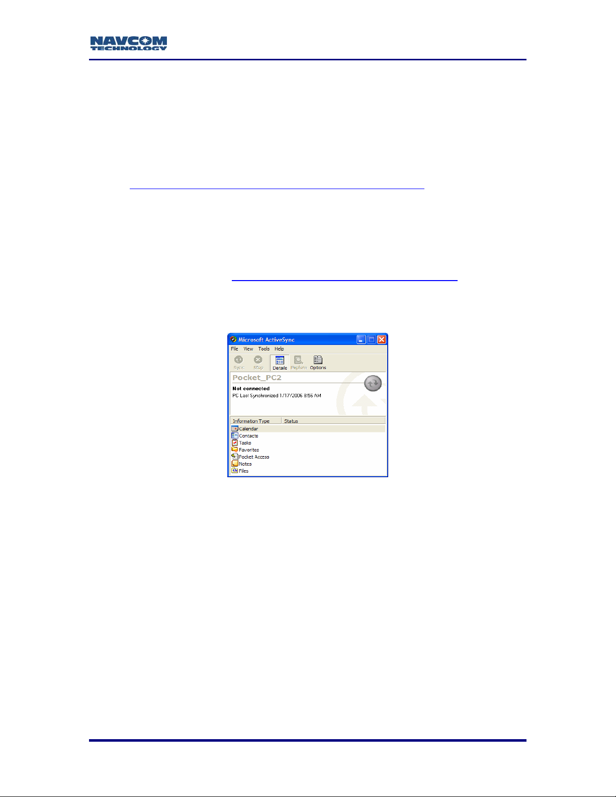
Figure 2: Active Sync™ Connections Settings Options
9 Check the appropriate box that best suits the PC-to-handheld link.
9 Click on the Get Connected button.
Figure 3: Active Sync™ Get Connected
9 Follow the displayed instructions.
9 Press Next, and Active Sync™ will attempt to find the connected device.
2 - 12
Page 15
StarControl User Guide Rev. C
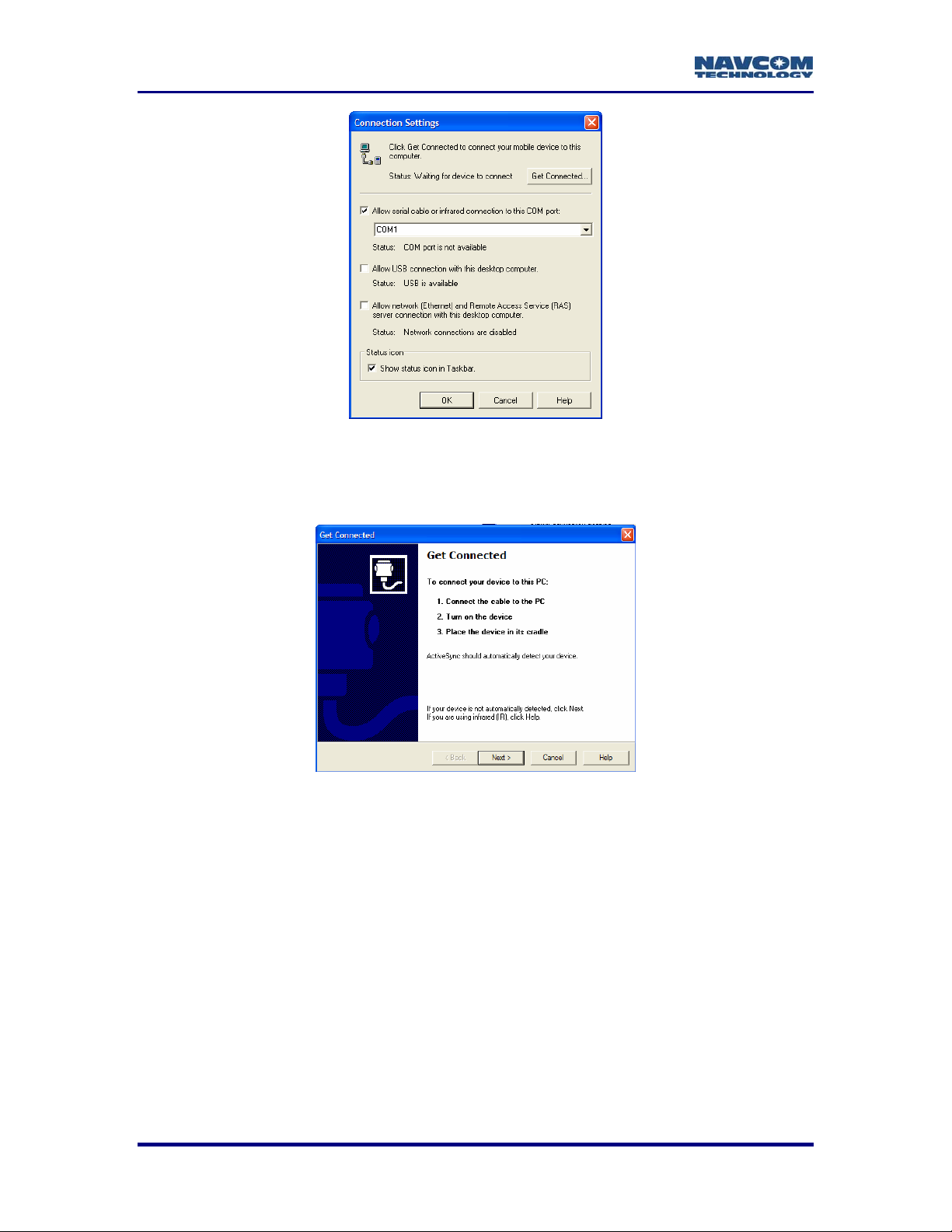
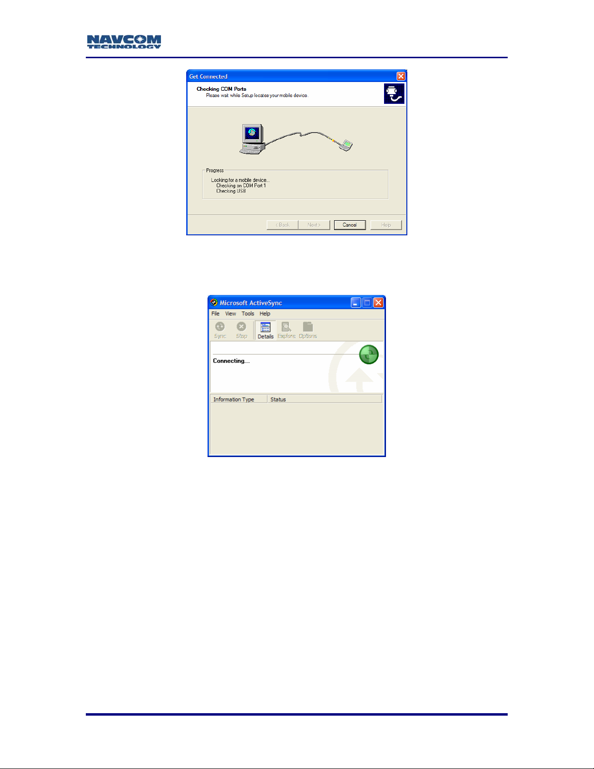
Figure 4: Active Sync™ Device Detection
Once a successful connection is made, Figure 5 will appear indicating that the handheld
was found and communication parameters are being setup.
Figure 5: Active Sync™ Device Connection
2 - 13
Page 16
StarControl User Guide Rev. C
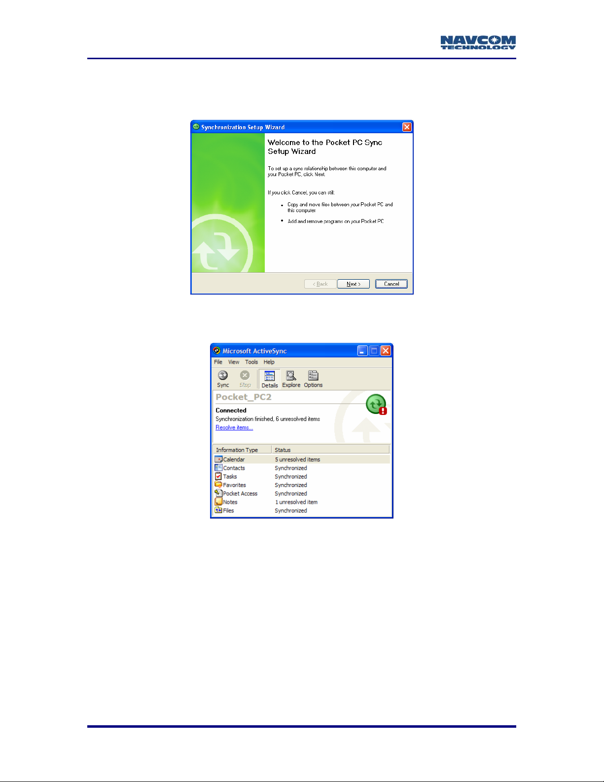
Figure 6 shows a Synchronization Setup Wizard.
9 Click the Cancel button when this window appears as it is not required for the
installation of StarControl.
Figure 6: Active Sync™ Device Connection Established
Figure 7 shows the final Active Sync™ screen after synchronization is complete.
Figure 7: Active Sync™ Device Connected and Synchronized
Now that a connection from the PC to the handheld is established, the StarControl
executable can be transferred to the handheld device.
9 Click on the Explore button on the Active Sync™ Tool Bar.
2 - 14
Page 17
StarControl User Guide Rev. C
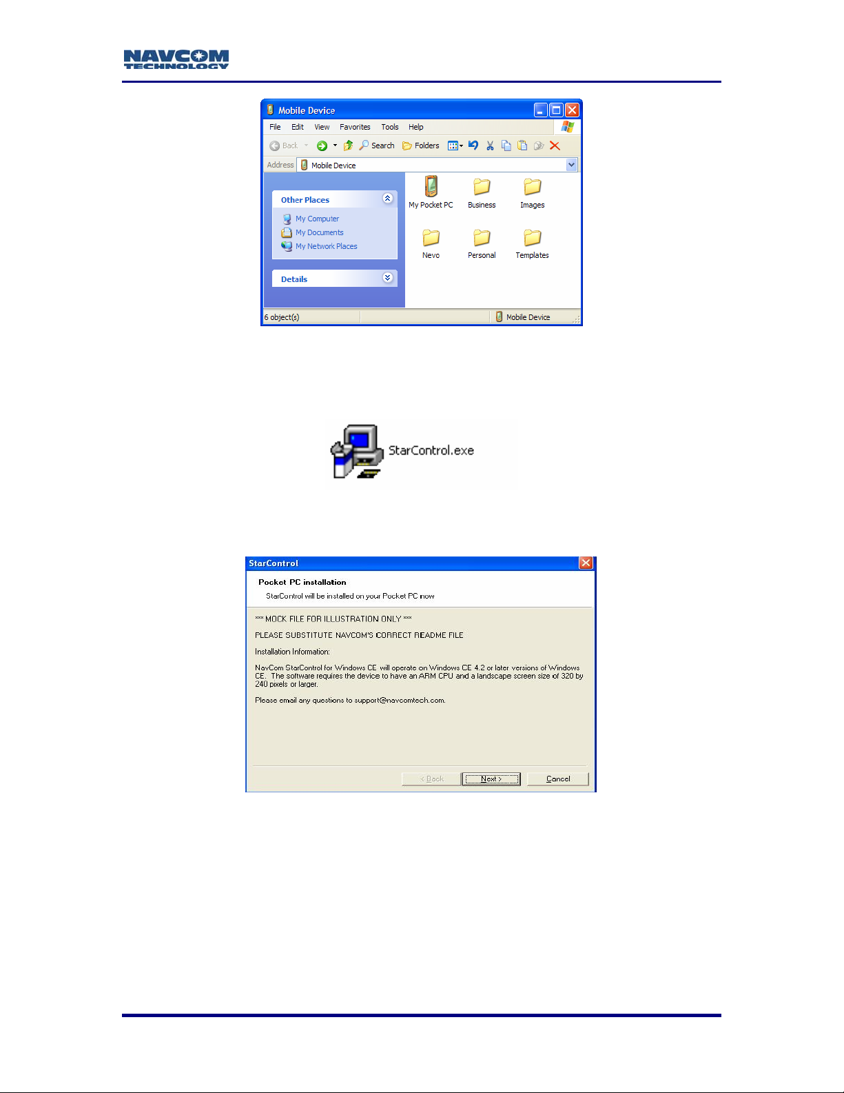
Figure 8: Active Sync™ PDA Explorer
9 Open the folder or drive on the PC where the StarControl executable resides.
9 Double Click on StarControl.exe
Figure 9: StarControl Executable
9 Click Next.
Figure 10: StarControl Executable Installation
9 Read through License Agreement.
9 Accept the license agreement to proceed with installation.
9 Click Finish.
2 - 15
Page 18

StarControl User Guide Rev. C
Figure 11: StarControl License Agreement
StarControl Installation process begins.
Figure 12: StarControl Installation Process
9 Follow instructions displayed on the PDA.
StarControl is copied to the desired location on the PDA.
Some handheld devices do not contain a backup battery. If the handheld
device does not contain a backup battery, save the executable to the
memory card.
2 - 16
Page 19

StarControl User Guide Rev. C
Chapter 3................................................................ Getting Connected
With StarControl executable located on the handheld device, connect serial port 1 of the
handheld to Com 2 of the GPS receiver.
Com 2 of the NavCom GPS receiver is defaulted to the Control Port. This
procedure assumes Com 2 to be Control.
Setup Screen
Execute the StarControl program on the handheld device. The Setup screen is the initial
screen displayed when StarControl starts up. The Setup screen contains all of the
elements required to connect to the GPS unit with the handheld device. StarControl is
not connected to the receiver yet.
Figure 13: StarControl Setup Dialog
Controller Port
The Controller Port is the physical port on the PDA used to connect to the GPS unit.
Once a connection between StarControl and the receiver is established, StarControl will
configure the receiver port as control; the other port will be assigned as Data & NMEA
output.
Baud Rate
The Baud Rate specifies the PDA connection rate to the GPS unit. A list of available
baud rates is displayed by clicking on the down arrow. If a specific baud rate is chosen
from the menu, StarControl will attempt to connect to the unit until a successful
connection is established or a timeout occurs.
3 - 17
Page 20

StarControl User Guide Rev. C
Auto Baud
The Auto option cycles through the available baud rates (Figure 14) and attempts a
connection at each rate. This continues until the unit connects successfully or a timeout
occurs.
Figure 14: StarControl Setup Port & Baud Rate Options
Connection Sequence
The Connect button initiates the communication between the controller and the GPS
receiver.
9 Press the Connect button.
A green animated arrow indicates that StarControl is attempting to connect to the
receiver at the chosen baud rate. If Auto baud is chosen the text field at the bottom will
display the current baud rate for each attempt. A cancel button is available to halt the
process and open the Setup screen.
Figure 15: StarControl Attempting to Connect to Receiver
Cancel may be pressed at anytime during the connection sequence.
3 - 18
Page 21

StarControl User Guide Rev. C
A successful connection is indicated by the green Check image
Figure 16: StarControl Successfully Connected to Receiver
9 Press the Continue button to return to the Setup screen. In the event of an
unsuccessful connection, the green arrow will not be displayed. Instead a red X
is displayed. Press the Close button to return to the Setup screen.
Figure 17: StarControl Unsuccessfully Connection Attempt to Receiver
3 - 19
Page 22

StarControl User Guide Rev. C
This page is left blank intentionally
3 - 20
Page 23

StarControl User Guide Rev. C
Chapter 4.....................................................................Receiver Status
Status screens provide an area where the receiver operating parameters are viewed. To
access Status, go to the View menu and choose Status from the drop-down list.
Status Screens
Diagnostics
The Diagnostics screen displays a snapshot of the GPS unit’s current operating state.
The green checks indicate that the receiver is operating correctly or that particular mode
is active. A Red X indicates that the receiver is either not operating in a particular mode,
or the information has not been retrieved from the receiver. This screen updates at a 2second interval. Table 1 describes how a green check or red X is determined on the
Diagnostics screen.
If all Diagnostic icons are red X’s, StarControl is: 1) not receiving the
information to update the screen from the receiver; or 2) StarControl has
lost connection with the receiver.
Figure 18: StarControl Status\Diagnostics Screen
4 - 21
Page 24

StarControl User Guide Rev. C
Table 1: Diagnostic Tab Elements
Property Green Check If Red X If
Receiver
Detected
No. of
Satellites
Single
Frequency
Dual
Frequency
PDOP
SBAS The receiver is in WAAS/EGNOS navigation
StarFire™ The receiver is in StarFire navigation
RTK
(fixed)
A Navigation or Solution Control read message
received
The number of satellites used in navigation is
greater than the minimum required
The receiver is in Single frequency navigation
(Stays Green if Dual is achieved)
The receiver is operating in Dual frequency
navigation
The DOP value is less than the maximum
acceptable PDOP set in Solution Control
The receiver is in RTK FIXED navigation
Satellites are not used
Not navigating
True single or no
navigation achieved
The DOP value is more
than the maximum
acceptable PDOP set in
Solution Control
No SBAS service is
available
StarFire signal is
unavailable
The receiver is operating
in RTK FLOAT mode, or
non RTK navigation
Version Info
The Version Info dialog details the receiver’s options capabilities, and its software
versions for all internal modules.
Figure 19: StarControl Status\Version Screen
The Version Info tab is a single tab, which can be scrolled through to
view all of the version and option information. The graphic above is used
only to display all available information.
4 - 22
Page 25

StarControl User Guide Rev. C
Satellites
The Satellites screen displays a snapshot of the satellite tracking status.
Figure 20: StarControl Status\Satellites Screen
Satellites Visible is the total number of GPS satellites available at the moment,
based on current almanac information.
Satellites Tracked L1 is the total number of GPS satellites under track at the
moment on the L1 signal only.
Satellites Tracked L2 is the total number of GPS satellites under track at the
moment on the L2 signal only.
Satellites Used is the total number of GPS satellites actually in use to compute a
position solution.
PDOP is the Position Delusion of Precision value of the current epoch, given the
geometry of the satellites currently in use.
4 - 23
Page 26

StarControl User Guide Rev. C
Solution
The Solution screen displays the receiver’s calculated position. Latitude and longitude
can be displayed in D, DM, or DMS. Height is displayed in Ellipsoidal meters or feet.
This screen also displays: Mean Sea Level (MSL) Altitude in meters or feet, Speed Over
Ground (SOG) in meters per second or feet per second, and Course Over Ground
(COG) in degrees North.
Figure 21: StarControl Status\Solution Screen
Table 2: Solution Screen Navigation Modes
Navigation Mode Description
Non Differential Receiver is navigating in Non Differential Mode
Receiver is navigating in WAAS Code Single Mode
dGPS (Code)
RCP
RTK
Receiver is navigating in WAAS Code Dual Mode
Receiver is navigating in RTCM+(CodeBase) Mode
Receiver is navigating in RTG Single Mode
Receiver is navigating in RTG Dual Mode
NCT RTK - navigating with NavCom RTK corrections
RTCM RTK - navigating with RTCM RTK corrections
CMR RTK - navigating with CMR RTK corrections
CMR+ RTK - navigating with CMR+ RTK corrections
4 - 24
Page 27

StarControl User Guide Rev. C
Solution Plot
The Solution Plot displays a graphical 2D representation of the receiver’s current
position relativity. Points are added to the plot screen indicating each epoch processed.
The default radial distance between the origin and the outermost ring is 2 meters. The
plot screen consists of 5 rings of equal distance. The Solution Plot screen range is from
0.5 meters to 20 meters.
Figure 22: StarControl Status\Solution Plot Screen
To interact with the 2D position plot, “Tap and Hold” on right side of the solution plot over
the grey area to activate a pop up menu (shown in Figure 23).
Figure 23: StarControl Status\Solution Plot Screen Tap & Hold Menu
4 - 25
Page 28

StarControl User Guide Rev. C
9 Extents - Select a new radial distance for the solution plot. The current distance
is displayed when opened. Distance may be set from 0.5 to 20.0 meters in 0.5
meter increments. Press OK to apply the entered radius and update the plot.
Previously displayed points are lost.
9 Cancel returns to the plot screen without applying changes.
Figure 24: StarControl Status\Solution Plot Screen Tap & Hold Extents
9 Origin - Resets the center point of the Solution Plot screen to the next received
point.
9 Zoom In - Will zoom in the Solution Plot screen by a factor of 2. Points previously
displayed are lost.
9 Zoom Out - Will zoom out the Solution Plot screen by a factor of 2. Points
previously displayed are lost.
9 Clear - Will clear all Solution Plot updates from the screen.
4 - 26
Page 29

StarControl User Guide Rev. C
Chapter 5.................................................................................. Profiles
Profiles are preconfigured XML files that are uploaded to the GPS receiver to setup the
receiver’s operational characteristics; e.g.: a Base RTK receiver or a Rover RTK
receiver, etc. StarControl provides the ability to create profiles and save them in a list to
be used at a later time. These files can be used, reused, and shared from one handheld
device to another.
Profiles are stored as XML files in the NCTProfiles directory with a .NCP (NavCom
Profile) extension. The NCTProfiles folder is created on the handheld device, if it does
not already exist. The folder or files can be beamed from one handheld device to
another using IR, Bluetooth, or transferred from the PC to the handheld using Microsoft
Active Sync™. The NCTProfiles folder is created in the same location as the StarControl
executable.
The Profile options are accessed by clicking on View / Profile on the StarControl menu
bar. The Profile tabs are used to create, modify, upload, and save profiles. There are 7
tabs that configure a given profile. All profile configuration screens are to the right of the
main Profile tab, as shown in Figure 25. StarControl initializes with a default profile that
is uploaded and written to the NCTProfiles folder as default.ncp each time the profile tab
screens are activated. It does not upload this default profile until the Upload Profile
button is clicked.
®
The default profile .NCP file is write-protected so no changes made will
be saved to the default file.
The Profile options chosen must not exceed the option limits of the receiver;
e.g.: if the receiver is optioned for 5Hz nav maximum, do not send a profile that
requests >5Hz nav. This will cause a failure in the profile uploading sequence.
Profile
Figure 25: StarControl Profile Tab
5 - 27
Page 30

StarControl User Guide Rev. C
Selection Configuration
This pull down menu list displays the default profile and all saved profiles. All profiles
with the .NCP extension in the NCTProfiles folder are displayed in the list. Profile fields
are not maintained in memory, so any changes made will be lost if the profile is not
saved.
New
Click this button to enter a name for a new profile.
Figure 26: StarControl Profile \ New Screen
Lose Changes warning appears when a newly created profile in the list is modified, or
when attempts to view another Profile from the list are made. Continuing without saving
changes to the current profile will be lost if it is not saved before switching to the next
profile. When a new profile is created, StarControl populates the profile tab fields with
values from the default.ncp profile and the new profile is made active.
The new file is not saved in the NCTProfiles folder until the Save button
on the Profile tab is clicked.
Copy
Clicking Copy duplicates the selected profile in the Select Configuration drop down list.
Enter a name for the copied profile in the Enter New Profile Name screen. Lose
Changes warning appears, when the copied profile in the list is modified or attempts are
made to view another profile from the list. Continuing without saving changes to the
current profile will be lost if it is not saved before switching to the next profile. The copied
profile created in StarControl populates the profile tab fields with values from the source
profile and the new profile is made active.
The new file is not saved in the NCTProfiles folder until the Save button
on the Profile tab is clicked.
5 - 28
Page 31

StarControl User Guide Rev. C
Save
The Save function updates the current profile by writing the field values out to an XML
file with the .NCP extension.
Changes cannot be saved to default.ncp since the file is written each
time the profile dialogs are opened. An error box directs to copy or create
a new file.
Delete
Delete will remove the current profile from the Select Configuration drop down list.
The default file cannot be deleted since StarControl requires it for
operation. An error dialog displays if an attempt is made to delete this file.
Upload Profile
This button is active only if a connection with the GPS receiver is active. Uploading a
Profile sets all of the necessary controls of the GPS receiver. This function is described
in more detail in Chapter 6 Tools.
GPS
Figure 27A: GPS Auto Height Options Figure 27B: GPS Manual Height Options
The GPS tab controls the Tracking and Navigation settings in the receiver. Setting the
modes here is also reflected in the Status\Diagnostic screen. If the RTK field is checked
in the Desired Operating Modes area of the GPS tab, the Correction Format, Max RTK
Age, Reference Station ID must also be selected on the RTK tab. Figure 27A shows the
GPS tab format when a 3D or Auto navigation solution is desired. Figure 27B shows the
GPS tab format when a 2D navigation solution is preferred. When the solution is
changed to 2D and the Height field changed to “Manual”, a Manual Height field displays
to enter the ellipsoidal height value. The receiver uses this constant for every epoch. If
the Solution is changed to 3D, the Manual Height field is removed.
5 - 29
Page 32

StarControl User Guide Rev. C
The View\Status\Diagnostic tab shows a green check for the active
navigation mode. If all Nav Modes are checked on the GPS tab, only the
Nav Mode currently in use will have a green check mark.
The GPS tab sets the controls for navigation position update rate, and measurement
usage limitations. The available choices for Navigation Rate and Parameters are
detailed in Table 3.
Table 3: GPS Tab Navigation Options
Property Possible Values
Navigation Rate 1, 2, 5, 10, 25 Hz
Navigation Elev Mask 0 - 89 degrees
Maximum PDOP 5, 10, 15, 20, 25.5
Min SVs for Solution 3 – 10 (inclusive)
Solution
Height
Continued on next page
2D = Constrain Height
3D = Compute Height
Manual = No auto transition,
use constrained Height
Auto = Compute Height
5 - 30
Page 33

StarControl User Guide Rev. C
NMEA
The NMEA screen enables or disables up to 11 NMEA messages for output from the
receiver to the StarControl port.
Figure 28: NMEA Tab Options
Table 4: NMEA Output Messages & Data Rates
NMEA Message Rate (seconds)
GGA Disabled, 1, 5, 10
GSA Disabled, 2, 5, 10
GSV Disabled, 2, 5, 10
VTG Disabled, 1, 5, 10
GLL Disabled, 2, 5, 10
GST Disabled, 2, 5, 10
RMC Disabled, 2, 5, 10
ZDA Disabled, 2, 5, 10
ALM Disabled, On Change
SET Disabled, 2, 5, 10
GBS Disabled, 2, 5, 10
5 - 31
Page 34

StarControl User Guide Rev. C
SBAS
The SBAS screen sets the WAAS/EGNOS mode to automatic or manual. If these
corrections are available, they will be used in navigation. The receiver will not use these
corrections if a more precise differential correction source is checked and available in
the GPS screen. In this scenario, the SBAS corrections will be used as a “fallback”
source when the more precise source of corrections is no longer available. If the SBAS
corrections are the sole source of aided navigation, remove the check marks from all the
other Operating Modes on the GPS tab (Refer to Figure 27). Choosing Auto from the
drop down menu in the SBAS screen sets the receiver to choose the best PRNs
available.
In manual mode, the Preferred and Alternate PRNs cannot be the same
value.
Figure 29A: SBAS Auto Tab Options Figure 29B: SBAS Manual Tab Options
RTK
This screen is used to configure the receiver as either a Base or Rover. Base/Rover
configuration is obtained through the Mode drop-down list. The Correction Rate, and
Base Position Rate option fields become available when Base is chosen from the list.
When configuring a base station the initial position is obtained from either the
Tools\Base Position option or the Tools\QuickStart option; both of which will be
discussed in detail later in Chapter 6 Tools.
Configuring the unit as a base station requires setting the output corrections to a port
and scheduling the correction messages. Port Configuration is based on the correction
type, and whether or not an external or internal communication link will be used. Table 5
details the available options for the RTK Base configuration, while Table 6 details the
available configurations for the RTK Rover.
5 - 32
Page 35

StarControl User Guide Rev. C
Figure 30A: Base RTK Tab Options Figure 30B: Rover RTK Tab Options
Table 5: Base Correction Output Messages, Status, & Data Rates
Field Options
Mode Base (Rover)
Correction Output Format
Reference Station ID
Correction Rate 1Hz – 10Hz
Base Position Rate 10 Sec, 20 Sec, 30 Sec
RTCM RTK, CMR, NavCom, RTCM Code,
CMR+
0 – 99 for CMR, CMR+ and 0 – 1023 for
NavCom, RTCM RTK
If Internal Radio is selected, StarControl will assign correction output to
the Radio port. If External is selected, StarControl will assign corrections
output to the receiver port that is not currently connected to the hand-held
device.
Table 6: Rover Correction Input Messages & Data Age Values
Field Options
Mode Rover (Base)
Correction Format RTCM RTK, CMR, NavCom, RTCM dGPS,
CMR+
Reference Station ID 0 – 99 for CMR, 0 – 1023 for NavCom, RTCM
(0 = use any Base Station ID received)
Maximum RTK Age 3 Sec, 10 Sec, 15 Sec, 30 Sec, 60 Sec
Maximum dGPS Age 60 Sec, 120 Sec, 180 Sec, 240 Sec, 300 Sec
StarControl will direct the receiver to collect corrections from the Radio port. If
External is selected, StarControl will direct the receiver to collect corrections from
the receiver port that is not currently connected to the hand-held device.
5 - 33
Page 36

StarControl User Guide Rev. C
Radio
Correction Port selection determines the dGPS correction input/output port.
Figure 31A: No Radio Figure 31B: Internal Radio Figure 31C: External Radio Tab
Selecting No Radio for the Correction Port causes the remaining choices to disappear.
dGPS corrections are transmitted or received via the Data Port which is the receiver’s
Com1 by default.
The Internal Radio field on the Radio tab is dependent on Base (master)/ Rover (slave)
settings on the RTK tab. The default Power Level is 1000 mW, and the default Network
ID is 1. Internal Radio directs the corrections to be output or received by the internal
radio for a base and rover.
External Port configures the data port baud rate of the external device and defines which
receiver com port is used for control. If Port 2 is control, then Port 1 is external (for dGPS
corrections).
Table 7: Internal Radio Mode & Power Settings
Field Options
Correction Port No Radio, Internal Radio, or External Port
Internal Radio Mode
Slave = Used if configuration is a rover
Master = Used if configuration is a base
10, 50, 100, 250, 500, 750, 1000 mW, or OFF. The rover
Power Level
internal radio must be set to a power level other than “OFF”
to receive dGPS corrections. Selecting “OFF” removes DC
power to the receiver.
Network 1 (Factory Default) – 99
5 - 34
Page 37

StarControl User Guide Rev. C
Antenna
This screen allows entry of the antenna offset to adjust vertical height for a tripod or pole
mount, use the Slant Height for this entry. The available range is 0 to +32767mm. The
Phase Center values for the NavCom recommended antennas, and the self contained
pole mount receivers can be obtained from the NavCom Website by selecting Antenna
Calibration Values at http://www.navcomtech.com/Support
http://www.navcomtech.com/Support/DownloadCenter.cfm?category=antenna
click on the appropriate product line to obtain the phase center values for that specific
product. The Phase Center values are also on a sticker located on the bottom of
NavCom antennas.
The negative or positive sign for the Phase Center Adjustment is chosen via the dropdown list just left of the value input field.
The Radius information of the antenna is given in the product User Guide. The Pole
Mount versions of NavCom GPS receivers have two radius values; one to the outermost
edge of the antenna bumper, and the second to the outermost edge of the battery
compartment.
(following this link:
). Then
Figure 32: Antenna Tab
Table 8: Antenna Bias Adjustment Ranges
Field Options Max Range
Use Antenna Bias Checked = Use Bias N/A
Sign + or – Phase Center Value N/A
Phase Center
Adjust
Radius Of Antenna Value in mm, antenna radius 0 to +32766
Slant Height Value in mm, slant height 0 to +32766
Value in mm, combines with the sign value -127 to +127
Setting the Antenna Bias DOES NOT change NMEA GGA height.
5 - 35
Page 38

StarControl User Guide Rev. C
This page is left blank intentionally
5 - 36
Page 39

StarControl User Guide Rev. C
Chapter 6......................................................................................Tools
There are 5 sub-items under Tools of the StarControl menu bar.
9 Data Logging Setup
9 QuickStart Starfire
9 Base Position Input
9 Upload Profiles
9 External Device Configuration
Data Logging
Start Logging
Figure 33: Tools Option Tab
Figure 34: Data Logging Tool
The Start Logging button is enabled when the unit is not logging, and disabled when the
unit is logging data. GPS data is logged internally to the on-board 64 MB memory
module. When the logging tool starts up, the controller poles the GPS unit to obtain the
6 - 37
Page 40

StarControl User Guide Rev. C
receiver’s logging status. The screen updates with the amount of Free Space available
on the internal memory module.
The internal memory filename format is DOS 8.3 on the memory module. StarControl will
use YYYYMMDD.000 as the mask for internal data logging file names. As more files are
created on the memory module for a single day, the numbered extension will increment
by one each time a new file is generated; e.g. 000, 001, 002, 003, etc. The maximum
number of extensions for a single day is 999. Once the End-of-GPS-Day is reached, and
a new logging file is initiated, the extension counter resets to 000. More files can be
logged as available memory will allow.
The receiver will schedule the messages shown in Table 8 to the Log Port when the
Start Logging Button is initialized. These messages are added to any messages already
scheduled in the existing receiver output list and will not reset the list.
Table 9: Internal Logging Message List
Msg. ID Messages Port Rate
0x44 Satellite Almanac Log On Change
0x81 Satellite Ephemeris Log On Change
0x86 Channel Status Log On Change
0xB0 Raw Pseudorange Log On Change
0xB1 Position, Velocity and Time Log On Change
0xB4 Event/Marker Log On Change
Stop Logging
The Stop Logging button is disabled when the unit is not logging, and enabled when the
unit is logging.
Status
The Status field indicates whether or not logging is active.
Free Space
The Free Space box shows the percentage of Megabytes currently free on the internal
memory card.
Progress Bar - The progress bar graphically shows the amount of memory currently
being used.
Close - The Close button returns to the previous dialog, but does not disable logging.
QuickStart
QuickStart is a feature that eliminates the convergence period for the StarFire Series
NavCom GPS receivers. This function allows the StarFire RTG navigation solution to be
initialized to an accurately known ITRF00 position and therefore eliminate lengthy
convergence times. Any error or bias in the QuickStart position entered is immediately
and continually applied to the calculated position and may require more than the normal
6 - 38
Page 41

StarControl User Guide Rev. C
convergence period to eliminate. Therefore, always try to use the most accurate position
possible.
Figure 35: Quick Start Tool
Latitude, Longitude, & Height
Enter the known ITRF2000 position in these fields, ensuring that the proper hemisphere
and height indicators are chosen.
There are three coordinate format choices; Degrees, Degrees & Minutes, and Degrees
Minutes & Seconds.
The choices for height format are U.S. Feet, and Meters.
After entering the appropriate information, click the Apply button and this will initiate the
QuickStart.
While a QuickStart operation is in progress, a check is performed at each
1Hz navigation epoch, which compares the 3D radial distance between
the RTG code solution and the ‘known’ ITRF2000 position input with the
QuickStart initiation request. If this distance exceeds 25 meters on the
first QuickStart epoch, or 15 meters on any of the subsequent epochs in
the 50 second period that QuickStart is being initiated, QuickStart is
terminated, and RTG navigation is reset (full convergence required).
Base Position
Used in conjunction with a Base Profile, the base station position must be entered or, if
the base station position is unknown the receiver can perform a self survey.
6 - 39
Page 42

StarControl User Guide Rev. C
Figure 36: Base Position Tool
Latitude, Longitude, & Height
Enter the known position in these fields, ensuring that the proper hemisphere and height
indicators are chosen.
There are three coordinate format choices; Degrees, Degrees & Minutes, and Degrees
Minutes & Seconds.
The choices for height format are U.S. Feet, and Meters.
Self Survey
If the base station antenna position is unknown, click Start button to initiate a Self
Survey. While the Self Survey is active, this button is disabled.
The longer the Self Survey, the more accurate the base position will be.
The Self Survey is an average of the total position fixes obtained over
time. For the sake of accuracy in transmitted corrections, a Self Survey
must be longer than 15 minutes.
The Stop button will end the Self Survey period. When the Self Survey is inactive, this
button is disabled.
The Apply Position button submits the Self Surveyed position to the receiver.
The Close button closes the Base Position screen and returns to the previous
StarControl screen. This button is disabled when the Apply Position button is clicked,
until the receiver acknowledges the base position.
6 - 40
Page 43

StarControl User Guide Rev. C
External Device Configuration (Passthrough)
The Passthrough tool allows StarControl to send/receive text data from one serial port
on the receiver to the other serial port. This feature proves useful when configuring a
device connected on the receiver port that is not configured as the Controller port or
hand-held device port. It can also serve as a way to transmit ASCII text to a remote
radio.
The current version of StarControl contains the following list of modem AT commands:
ATZ, ATH0, ATH1, ATD
Each of these commands can be selected from the list and modified with text extensions
if required, or a message can be typed in the External Mode Configuration field and sent
out of the opposite port.
Figure 37A: Non Passthrough Tool Figure 37B: Passthrough Tool
The Enable button turns on the Passthrough mode feature. When Passthrough is
enabled, all other communication on the receiving port is temporarily disabled to allow
unobstructed communication through the port. When Passthrough is initiated, the Enable
button changes to Disable as shown in Figure 37B.
The Disable button turns the Passthrough mode feature off. When Passthrough is
disabled, all other communication on the receiving port is restored to pre-Passthrough
conditions.
The Send button transmits the command or data through to the Passthrough port.
The Communications Log area echoes any command sent via Passthrough, and
displays any information received from the PassThrough port.
The Mode field indicates the receiver’s Passthrough state, it also indicates which
receiver port is acting as the Passthrough port.
The Close button closes the Passthrough tool. The receiver will remain in the last
configured mode when the Passthrough tool is closed.
6 - 41
Page 44

StarControl User Guide Rev. C
Upload Profile
Upload Profile is active only when a connection is established with the GPS receiver.
Selecting Upload Profile opens the screen shown in Figure 38, to send a file of
preconfigured setup instructions to the receiver. Configuring a Profile is described in
Chapter 5 Profiles. Uploading a Profile sets all of the necessary controls for the receiver
to perform as desired.
Figure 38: Upload Profile screen under Tools\Upload Profile menu
Choose the required profile from the Profile pull-down list, and click the Upload button.
During the upload process, a screen similar to Figure 39A will appear. After the upload is
complete, a screen similar to Figure 39B is displayed. Scroll to the end of the status
window to ensure that the Profile Upload is complete or view any errors. If errors are
present, scroll through the status window to see where the errors occurred. Chapters 7 &
8 provide detailed examples of rover and base configurations.
Do not cancel an upload while in progress. This causes a partial profile
upload, and leaves the receiver in an unknown state.
Figure 39A: Beginning of Upload Profile Figure 39B: Continuation of Upload Profile
6 - 42
Page 45

StarControl User Guide Rev. C
Chapter 7................................................................Base Configuration
This chapter provides step-by-step procedures to configure a base receiver. Rover is the
default configuration for a NavCom receiver, between uses the receiver state, Base or
Rover, may be unknown. StarControl sets the receiver, regardless of the actual current
state. The following example assumes a successful connection between StarControl and
the GPS receiver is established.
Create a profile to configure the receiver as a base, as outlined in Chapter 5
Profiles\Profile tab.
Figure 40: Base RTK Tab Options
Continued on next page
7 - 43
Page 46

StarControl User Guide Rev. C
The following example is an NCT RTK Base using the internal radio with the navigation
and data parameters set:
Table 10: Base Example Profile Settings
Profile Tab Function Options
Nav Rate 1Hz
Nav Elev Mask 7 degrees
GPS NCT RTK
NMEA NMEA Output
SBAS SBAS MODE
RTK (Base) Mode Base
Radio Internal Radio
Antenna Bias
Max PDOP 10
Min SVS for Nav Output 4
Solution 3D
Height Auto
ALM Disable
GGA Disable s
GLL Disable s
GSA Disable s
GST Disable s
GSV Disabled
RMC Disabled
VTG Disable s
ZDA Disable s
SET Disable s
GBS Disable s
Auto
Preferred PRN 120
Alternate PRN 121
Correction Format NavCom
Ref STN ID 3
Correction Rate 1 s
Base Position Rate 10 s
Correction Port Internal
Radio
Mode Master
Power Level 1000 mW
Network ID 10
Use Antenna Bias
Phase Center Sign Phase Center 85 mm
Antenna Radius 100 mm
Slant Height 90 mm
Unlike the procedure for setting up a Rover, setting the Base
configuration will require accessing several different StarControl screens
other than Profile.
7 - 44
Page 47

StarControl User Guide Rev. C
Step 1: Creating the Base Profile Parameters
Click View\Profile from the StarControl menu to display Figure 41.
Create a new uniquely named profile by clicking New, and typing in a name for the
profile.
Name the profile in a manner that reflects what the profile is configured to
do; in this case Base NCT RTK makes it easier to distinguish from other
profiles later on.
Figure 41: Profile Tab
Enter the navigation and data parameters from the aforementioned list by clicking the
appropriate tab. After all changes are made, return to the Profile tab and click Save. The
new profile is saved to the NCT Profiles folder, and will appear in the Select
Configuration drop-down list.
7 - 45
Page 48

StarControl User Guide Rev. C
Step 2: Uploading Profile Parameters
Select the newly created profile if it is not already visible in the Select Configuration area
of the Profile tab screen.
Click the Upload Profile button. During the upload process the StarControl screen will
update to that of Figure 42. This screen displays the upload progress. Notice that the
Upload button changes to Cancel while the upload is in progress.
Figure 42: Profile Upload Progress Screen
Do not cancel a profile upload.
After the upload is completed the Cancel button will revert back to Upload, and the
progress bar will be at 100% completion. If the upload is successful Figure 43A appears
and no errors are noted in the Status information.
However, if the upload is unsuccessful, Figure 43B will appear noting errors during the
upload and the area of the error found.
Note that an unsuccessful upload has the same affect and consequences
as if the upload is canceled causing a partial profile upload.
The receiver is in an unknown state. If a profile upload fails, upload the
Default profile before attempting to upload another profile. This forces the
receiver back to a known safe configuration.
7 - 46
Page 49

StarControl User Guide Rev. C
Figure 43A: Profile Upload Without Error Figure 43B: Profile Upload With Error
Step 3: Base Position Configuration
The Base Position can be entered in three different ways: Degrees; Degrees & Minutes
and Degrees Minutes & Seconds.
Figure 44: Base Position Tool
9 Manually enter the known position, in the Base Position screen, per the
procedure in Chapter 6 Tools\Base Position.
9 Click the Self Survey button and follow the procedure detailed in Chapter 6
Tools\Base Position\Self Survey. After the appropriate time, click the Apply
Position button.
The longer the Self Survey, the more accurate the Base Position as the
Self Survey is an average of the total position fixes obtained over time.
Self Survey must be longer than 15 minutes.
7 - 47
Page 50

StarControl User Guide Rev. C
Chapter 8.............................................................. Rover Configuration
This chapter provides a step-by-step procedure to configure a Rover receiver. Rover is
the default configuration for a NavCom receiver. Between uses the receiver state, Base
or Rover, may be unknown. StarControl sets the receiver, regardless of the actual
current state. The following example assumes a successful connection between
StarControl and the GPS receiver is established.
Create a profile to configure the receiver as a rover, as outlined in Chapter 5
Profiles\Profile tab.
Figure 45: Rover RTK Tab Options
Continued on next page
8 - 48
Page 51

StarControl User Guide Rev. C
The following example is a NCT RTK Rover using the internal radio with the navigation
and data parameters set:
Table 11: Rover Example Profile Settings
Profile Tab Function Options
Nav Rate 5Hz
Nav Elev Mask 7 degrees
GPS NCT RTK
Max PDOP 10
Min SVS for Nav Output 3
Solution 3D
Height Auto
ALM On Change
GGA 1 s
GLL 2 s
GSA 5 s
GST 10 s
NMEA NMEA Output
GSV Disabled
RMC Disabled
VTG 1 s
ZDA 2 s
SET 2 s
GBS 2 s
Auto
SBAS SBAS MODE
Preferred PRN 120
Alternate PRN 121
Correction Format NavCom
RTK (Rover) Mode Rover
Ref STN ID 0 (any)
Max RTK AGE 15 s
Max DGPS AGE 300 s
Correction Port Internal Radio
Radio Internal Radio
Mode Slave
Power Level 1000 mW
Network ID 10
Use Antenna Bias
Phase Center Sign -
Antenna Bias
Phase Center 85 mm
Antenna Radius 100 mm
Slant Height 90 mm
Step 1: Create the Required Rover Profile Parameters
Click View\Profile from the StarControl menu.
Create a new uniquely named profile by clicking New, and typing in a name for profile.
8 - 49
Page 52

StarControl User Guide Rev. C
Name the profile in a manner that reflects what the profile is actually
configured to do; in this case NCT RTK rover makes it easier to
distinguish from other profiles later on.
Figure 46: Profile Tab
Enter the navigation and data parameters from the aforementioned list by clicking the
appropriate tab. After all changes have been made, return to the Profile tab and click
Save. The new profile is saved to the NCT Profiles folder and will appear in the Select
Configuration drop-down list.
Step 2: Uploading Profile Parameters
Select the newly created profile if it is not already visible in the Select Configuration area
of the Profile tab screen.
Click the Upload Profile button. During the upload process, the StarControl screen will
update to that of Figure 47. This screen displays upload progress. Notice that the Upload
button changes to Cancel while the upload is in progress.
Figure 47: Profile Upload Progress Screen
Do not cancel a profile upload.
8 - 50
Page 53

StarControl User Guide Rev. C
After the upload is complete the Cancel button will revert back to Upload, and the
progress bar will be at 100% completion. If the upload is successful, Figure 48A appears
and no errors are noted in the Status information.
However, if the upload is unsuccessful, Figure 48B will appear noting errors during the
upload and the area of the error found.
Note that an unsuccessful upload has the same affect and consequences
as if the upload is canceled causing a partial profile upload. The receiver
is in an unknown state. If a profile upload fails, upload the Default profile
before attempting to upload another profile. This forces the receiver back
to a known safe configuration.
Figure 48A: Profile Upload Without Error Figure 48B: Profile Upload With Error
8 - 51
Page 54

StarControl User Guide Rev. C
This page is left blank intentionally
8 - 52
Page 55

StarControl User Guide Rev. C
Glossary
WAAS (Wide Area Augmentation System) a set of corrections for the GPS satellites,
which are valid for the Americas region. They incorporate satellite orbit and clock
corrections.
RCP a NavCom Technology, Inc. proprietary processing technique in which carrier
phase measurements, free of Ionospheric and Troposphere effects are used for
navigation.
RTG Real Time GIPSY, a processing technique developed by NASA’s Jet Propulsion
Laboratory to provide a single set of real time global corrections for the GPS satellites.
RTCM (Radio Technical Commission for Maritime Services) a standard format for
Differential GPS corrections used to transmit corrections from a base station to rovers.
RTCM allows both real-time kinematic (RTK) data collection and post-processed
differential data collection. RTCM SC-104 (RTCM Special Committee 104) is the most
commonly used version of RTCM message.
Compact Measurement Record (CMR) a standard format for DGPS corrections used
to transmit corrections from a reference station to rover sensors.
Glossary - 53
Page 56

StarControl User Guide Rev. C
This page is left blank intentionally
Glossary - 54
 Loading...