

Page 1
S
S
F
F--
3
3
0
0
5
5
0
0
GGNNSSSS PPrroodduucctt
UUsseerr GGuuiiddee
NavCom Technology, Inc.
20780 Madrona Avenue
Torrance, California 90503 USA
Tel: +1 310.381.2000
Fax: +1 310.381.2001
sales@navcomtech.com
www.navcomtech.com
Page 2

SF-3050 GNSS Product User Guide – Rev I
This page is left blank intentionally.
Page 3

SF-3050 GNSS Product User Guide – Rev I
Table of Contents
Table of Contents....................................................................................................................... i
List of Figures ................................ .......................................................................................... iv
List of Tables ........................................................................................................................... vii
Notices .................................................................................................................................... viii
Copyright ............................................................................................................................................ viii
Trademarks ........................................................................................................................................ viii
FCC Notice ......................................................................................................................................... viii
User Notice......................................................................................................................................... viii
Limited Warranty .................................................................................................................................. ix
StarFire™ Licensing ............................................................................................................................. ix
Software License Agreement ............................................................................................................... ix
USG FAR .............................................................................................................................................. x
Global Navigation Satellite System ....................................................................................................... x
Revision History ...................................................................................................................... xi
Use of This Document ............................................................................................................ xv
Related Documents ................................................................................................................................. xv
SF-3050 Quick Start Guide P/N 96-310033-3001 .............................................................................. xv
StarUtil 3000 User Guide P/N 96-310029-3001.................................................................................. xv
Sapphire Technical Reference Manual P/N 96-3120001-3001 .......................................................... xv
RINEXUtil User Guide P/N 96-310021-2101 ..................................................................................... xv
NavCom Release Notes ..................................................................................................................... xvi
Related Standards .................................................................................................................................. xvi
ICD-GPS-200 ..................................................................................................................................... xvi
IEC 60945, IEC 61108-1, IEC 61162-1, IEC 61162-2 ...................................................................... xvi
GLONASS ICD, Version 5.0, 2002 .................................................................................................... xvi
RTCM-SC-104 ................................................................................................................................... xvi
NTRIP ................................................................................................................................................. xvi
CMR, CMR+ ....................................................................................................................................... xvi
RINEX ................................................................................................................................................ xvi
QZSS ................................................................................................................................................. xvii
NMEA-0183 ....................................................................................................................................... xvii
Publicly Operated SBAS Signals ...................................................................................................... xvii
Chapter 1 Getting Started ................................................................................................... 1
Product Configuration Files ...................................................................................................................... 1
Connect Equipment .................................................................................................................................. 2
Save Folder/Files to PC............................................................................................................................ 3
Establish Communications ....................................................................................................................... 4
Determine Current Firmware Versions ..................................................................................................... 7
Determine Firmware Version via the Input Terminal ........................................................................... 9
Upload Software Options ....................................................................................................................... 10
Upload Software Options via the Input Terminal .................................................................................... 12
Upload Firmware .................................................................................................................................... 12
Upload a Unified Firmware File .............................................................................................................. 12
Upload a Single Firmware File ........................................................................................................... 14
Upload StarFire License ......................................................................................................................... 17
Confirm StarFire Navigation ............................................................................................................... 20
How to Cancel a StarFire License ..................................................................................................... 20
Factory Default User Profile ................................................................................................................... 21
Upload User Profile (optional) ................................................................................................................ 21
Enable or Disable Receiver Tracking and/or Use of Select Signals and Frequencies .......................... 21
Enable or Disable Receiver Use of Signals and Frequencies for Navigation ........................................ 21
Upload WebPages .................................................................................................................................. 22
i
Page 4

SF-3050 GNSS Product User Guide – Rev I
Chapter 2 Introduction ...................................................................................................... 25
System Overview .................................................................................................................................... 25
GNSS Sensor System ........................................................................................................................ 25
Performance Upgrade Path ............................................................................................................... 26
Accuracy............................................................................................................................................. 28
Features (for All Software Bundles) ................................................................................................... 28
SF-3050G ........................................................................................................................................... 30
SF-3050S ........................................................................................................................................... 31
SF-3050M........................................................................................................................................... 31
Bluetooth ............................................................................................................................................ 32
Ethernet Connection ............................................................................................................................... 32
Antennae ................................................................................................................................................ 33
Rover .................................................................................................................................................. 33
Base ................................................................................................................................................... 33
Airborne .............................................................................................................................................. 34
Controller ................................................................................................................................................ 34
Applications ........................................................................................................................................ 37
Unique Features ..................................................................................................................................... 37
Chapter 3 Web Server ....................................................................................................... 42
Accessing the WebServer .................................................................................................................. 42
Welcome Page ................................................................................................................................... 43
Receiver Location Bar ........................................................................................................................ 43
Main Menu.......................................................................................................................................... 44
Messages ........................................................................................................................................... 45
Configuration ...................................................................................................................................... 53
Utility ................................................................................................................................................... 59
Input Terminal .................................................................................................................................... 63
Help .................................................................................................................................................... 64
Chapter 4 Interfacing ........................................................................................................ 66
Electrical Power ...................................................................................................................................... 66
Proper Shutdown of SF-3050 ............................................................................................................ 69
Communication Ports ............................................................................................................................. 71
Supplied USB Device Cable .............................................................................................................. 74
Bluetooth Communications Setup ...................................................................................................... 76
Accessories ............................................................................................................................................ 81
Optional Data Cables ......................................................................................................................... 81
Logging to USB Flash Drive via USB Host Cable .............................................................................. 85
Direct Ethernet Connection via Static IP Address ............................................................................. 87
Event....................................................................................................................................................... 90
1 PPS...................................................................................................................................................... 91
Indicator Panel ........................................................................................................................................ 91
Chapter 5 Installation ........................................................................................................ 93
Antennae ............................................................................................................................................ 93
GNSS Sensor ..................................................................................................................................... 94
Communication Port Connectivity ...................................................................................................... 95
GNSS Antenna Connector ................................................................................................................. 96
Basics of RTK Surveying ........................................................................................................................ 98
Chapter 6 Configuration ................................................................................................. 101
Factory Default Output Messages ........................................................................................................ 102
Message Descriptions ...................................................................................................................... 103
User Profiles ......................................................................................................................................... 104
Profile NONE .................................................................................................................................... 105
Avoiding User Profile Loading Errors ............................................................................................... 105
Third-Party Controller Configuration Settings....................................................................................... 105
Over the Air StarFire Licensing ............................................................................................................ 105
ii
Page 5

SF-3050 GNSS Product User Guide – Rev I
Over the Air Broadcast ..................................................................................................................... 106
Verify License Is Saved .................................................................................................................... 106
Setting Up a StarFire Priority Network ................................................................................................. 107
RapidRecovery ................................................................................................................................. 107
Failed Search ................................................................................................................................... 108
Reassignment of StarFire Network List ........................................................................................... 108
Chapter 7 Safety Instructions ........................................................................................ 111
Transport .......................................................................................................................................... 111
Maintenance ..................................................................................................................................... 111
External Power Source .................................................................................................................... 111
Safety First ....................................................................................................................................... 111
A GNSS Module Specifications ......................................................................................... 113
Features ............................................................................................................................................... 113
Performance ......................................................................................................................................... 114
Tracking Characteristics ....................................................................................................................... 114
Signals Tracked ............................................................................................................................... 114
Receiver Noise Figure ...................................................................................................................... 115
Time-to-First-Fix ............................................................................................................................... 115
Signal Reacquisition ......................................................................................................................... 115
Dynamics.......................................................................................................................................... 115
Measurement Performance.............................................................................................................. 116
Pull-in Times .................................................................................................................................... 117
User-Programmable Output Rates .................................................................................................. 118
Data Latency and Memory ............................................................................................................... 118
1PPS ................................................................................................................................................ 118
Connector Assignments ................................................................................................................... 119
Input/Output Data Messages ........................................................................................................... 119
Satellite-Based Augmentation System Signals ................................................................................ 120
StarFire Rapid Recovery .................................................................................................................. 120
Physical and Environmental ............................................................................................................. 120
LED Display Functions ..................................................................................................................... 121
B Antenna Specifications................................................................................................... 123
Rover/Airborne Antennae Radiation Pattern ........................................................................................ 126
Base Antenna Radiation Pattern .......................................................................................................... 127
C StarFire ............................................................................................................................ 129
Description ............................................................................................................................................ 129
Infrastructure ........................................................................................................................................ 129
Reliability .............................................................................................................................................. 130
StarFire Satellites ................................................................................................................................. 131
How to Access the StarFire Service ..................................................................................................... 132
D Event Input Configuration .............................................................................................. 135
E Networked Transport of RTCM Internet Protocol (NTRIP) Setup ................................. 137
Configure the SF-3050 for Wireless Connection .................................................................................. 137
Configure the NTRIP Server ............................................................................................................ 137
Configure the NTRIP Client.............................................................................................................. 137
F Software License Agreement ......................................................................................... 141
Software License Agreement for NavCom Technology, Inc. GNSS StarFire™ Receiver ................... 141
Open Source Software License Appendix ....................................................................................... 146
G RoHS Certification .......................................................................................................... 155
Description ....................................................................................................................................... 155
RoHS 认证........................................................................................................................................ 162
Glossary ................................................................................................................................ 169
iii
Page 6

SF-3050 GNSS Product User Guide – Rev I
List of Figures
Figure 1: SF-3050 Rear View .............................................................................................................................2
Figure 2: NavCom Sub-Folders on PC ...............................................................................................................3
Figure 3: StarUtil 3000 – Main Window ..............................................................................................................4
Figure 4: Port Configuration ................................................................................................................................5
Figure 5: StarUtil 3000 Communication Window ................................................................................................6
Figure 6: Connection at Incorrect Baud Rate .....................................................................................................7
Figure 7: Access to Receiver Options Tab .........................................................................................................7
Figure 8: Example of Installed Firmware ............................................................................................................8
Figure 9: Firmware Folder ..................................................................................................................................8
Figure 10: Comparing Current and Installed Firmware ......................................................................................9
Figure 11: Input Terminal – Firmware Versions .................................................................................................9
Figure 12: Input Terminal ....................................................................................................................................9
Figure 13: Version Command .......................................................................................................................... 10
Figure 14: Software Options ............................................................................................................................ 10
Figure 15: Software Options Upload................................................................................................................ 11
Figure 16: Successful Software Options Upload ............................................................................................. 11
Figure 17: Software Options Window .............................................................................................................. 11
Figure 18: Receiver Options Tab ..................................................................................................................... 13
Figure 19: File Upload – Unified File Loader Option ....................................................................................... 13
Figure 20: Firmware Folder ............................................................................................................................. 13
Figure 21: Ready to Downline Load File ......................................................................................................... 14
Figure 22: Finished with All Downline Loads ................................................................................................... 14
Figure 23: File Upload Window ........................................................................................................................ 15
Figure 24: Receiver Firmware Option .............................................................................................................. 15
Figure 25: Load Receiver Firmware ................................................................................................................ 15
Figure 26: Firmware Folder ............................................................................................................................. 15
Figure 27: Settings for GNSS Firmware .......................................................................................................... 16
Figure 28: Settings for PWRIO Firmware ........................................................................................................ 16
Figure 29: Progress Dialog Box ....................................................................................................................... 17
Figure 30: Position, Velocity, Time Menu Item ................................................................................................ 17
Figure 31: PVT Tab/Navigation Status Window .............................................................................................. 18
Figure 32: Navigation Modes Menu Item ......................................................................................................... 18
Figure 33: Set Navigation Modes/StarFire ON ................................................................................................ 18
Figure 34: StarFire License ............................................................................................................................. 19
Figure 35: Successful StarFire License Upload .............................................................................................. 19
Figure 36: StarFire Menu Item ......................................................................................................................... 20
Figure 37: Nav Mode: StarFire Dual GNSS ..................................................................................................... 20
Figure 38: Input Terminal – Cancel StarFire License ...................................................................................... 20
Figure 39: Input Terminal – [ETHCONFIG] ..................................................................................................... 22
Figure 40: Input Terminal – Save Profile ......................................................................................................... 22
Figure 41: Input Terminal – Format Memory Card .......................................................................................... 23
Figure 42: File Upload – Webpage Loader ...................................................................................................... 23
Figure 43: Webpage NCT Directory ................................................................................................................ 23
Figure 44: Load Webpages NCT file ............................................................................................................... 24
Figure 45: Input Terminal – Webcontrol .......................................................................................................... 24
Figure 46: SF-3050 Supplied Equipment ........................................................................................................ 35
Figure 47: Rover, Base, and Airborne Antennae ............................................................................................. 36
Figure 48: Windows Security Screen............................................................................................................... 42
Figure 49: Welcome Page ............................................................................................................................... 43
Figure 50: Location Bar ................................................................................................................................... 43
Figure 51: Welcome Page with Expanded Menu Bar ...................................................................................... 44
Figure 52: PVT Screen .................................................................................................................................... 45
Figure 53: Channel Status Screen ................................................................................................................... 47
iv
Page 7

SF-3050 GNSS Product User Guide – Rev I
Figure 54: Measurements Screen ................................................................................................................... 48
Figure 55: StarFire Status Screen ................................................................................................................... 50
Figure 56: StarFire Almanac screen ................................................................................................................ 51
Figure 57: NMEA View Screen ........................................................................................................................ 52
Figure 58: Skyplot Screen ............................................................................................................................... 53
Figure 59: Skyplot Rollover Info ....................................................................................................................... 53
Figure 60: Schedule Messages Screen ........................................................................................................... 54
Figure 61: NTRIP Config Screen ..................................................................................................................... 55
Figure 62: NTRIP Config Screen with StarFire Settings enabled .................................................................... 56
Figure 63: Navigation Modes Screen .............................................................................................................. 57
Figure 64: RTK Mode Screen .......................................................................................................................... 57
Figure 65: Self Survey Screen ......................................................................................................................... 58
Figure 66: Antenna Height Adjustment Screen ............................................................................................... 58
Figure 67: View/Load Profile Screen ............................................................................................................... 59
Figure 68: View/Load Profile Screen ............................................................................................................... 60
Figure 69: Firmware Update Screen................................................................................................................ 60
Figure 70: Data Logging Screen ...................................................................................................................... 60
Figure 71: Almanac Loader Screen ................................................................................................................. 61
Figure 72: Options and License Screen .......................................................................................................... 62
Figure 73: Change Password Screen .............................................................................................................. 62
Figure 74: Manage Accounts Screen .............................................................................................................. 63
Figure 75: Input Terminal Screen .................................................................................................................... 64
Figure 76: Help Screen .................................................................................................................................... 64
Figure 77: Universal Power Adapter ................................................................................................................ 67
Figure 78: AC Power Cord ............................................................................................................................... 67
Figure 79: Unterminated Power Cable without Filter ....................................................................................... 67
Figure 80: Power Cable Pin Assignment ......................................................................................................... 68
Figure 81: Proper External Power Source Setup ............................................................................................ 69
Figure 82: SF-3050 Front View ........................................................................................................................ 70
Figure 83: SF-3050 Rear View ........................................................................................................................ 70
Figure 84: Supplied Data Cables ..................................................................................................................... 72
Figure 85: COM1 Serial Cable Pin Assignment .............................................................................................. 74
Figure 86: COM2 Serial Cable Pin Assignment .............................................................................................. 74
Figure 87: USB Device Cable Pin Assignment ................................................................................................ 75
Figure 88: Search for devices in range ............................................................................................................ 76
Figure 89: Bluetooth Devices in Range ........................................................................................................... 76
Figure 90: Bluetooth Serial Port Icon ............................................................................................................... 77
Figure 91: Bluetooth Serial Port Connection ................................................................................................... 77
Figure 92: Bluetooth Serial Port ....................................................................................................................... 78
Figure 93: Bluetooth Properties ....................................................................................................................... 78
Figure 94: Port Configuration – Bluetooth ....................................................................................................... 79
Figure 95: Input Terminal – PING Command and Response .......................................................................... 80
Figure 96: SF-3050 Optional Data Cables ...................................................................................................... 81
Figure 97: Optional USB Host Cable Pin Assignment ..................................................................................... 82
Figure 98: Optional Ethernet Cable Pin Assignment ....................................................................................... 83
Figure 99: Optional USB Device/RS-232/RS-422 Y-Cable Pin Assignment .................................................. 84
Figure 100: Optional Ethernet/RS-232/1PPS Y-Cable Pin Assignment .......................................................... 85
Figure 101: Input Terminal – USBMODE ........................................................................................................ 86
Figure 102: Local Area Connection Window ................................................................................................... 88
Figure 103: Internet Protocol Window ............................................................................................................. 89
Figure 104: Ethernet Port Configuration .......................................................................................................... 90
Figure 105: SF-3050 Indicator Panel ............................................................................................................... 91
Figure 106: Rover, Base, Airborne GNSS Antennae ...................................................................................... 93
Figure 107: SF-3050 Base Plate Dimensions Without Mounting Brackets ..................................................... 95
Figure 108: SF-3050 Base Plate Dimensions with Mounting Brackets ........................................................... 95
Figure 109: Communication Port Connections ................................................................................................ 96
v
Page 8

SF-3050 GNSS Product User Guide – Rev I
Figure 110: RTK Setup – Good Line of Sight .................................................................................................. 99
Figure 111: RTK Setup – Poor Line of Sight ................................................................................................... 99
Figure 112: Rover GNSS Antenna Offset ...................................................................................................... 124
Figure 113: Rover (P/N 82-001020-3001) Antenna Dimensions ................................................................... 124
Figure 114: Airborne (P/N 82-001022-3001LF) Antenna Dimensions .......................................................... 125
Figure 115: Rover/Airborne GNSS Antenna Radiation Pattern ..................................................................... 126
Figure 116: Base (P/N 82-001021-3001LF) Antenna Dimensions ................................................................ 126
Figure 117: Base GNSS Antenna Radiation Pattern ..................................................................................... 127
Figure 118: StarFire Network ......................................................................................................................... 133
Figure 119: Event Cable Wiring Diagram ...................................................................................................... 135
Figure 120: DTE to DCE RS-232 Pin Assignments ....................................................................................... 170
vi
Page 9

SF-3050 GNSS Product User Guide – Rev I
List of Tables
Table 1: Performance Upgrade Path – Position & Data Rates ....................................................................... 26
Table 2: Performance Upgrade Path – Signals ............................................................................................... 27
Table 3: Performance Upgrade Path – RTK .................................................................................................... 27
Table 4: Performance Upgrade Path – 1PPS/Event ....................................................................................... 28
Table 5: Supplied Equipment ........................................................................................................................... 35
Table 6: SF-3050 Antennae ............................................................................................................................. 36
Table 7: External Power Cable Pin-Out ........................................................................................................... 66
Table 8: DC Power Cable Pin Assignments .................................................................................................... 68
Table 9: COM1 Serial Cable Pin-Outs (P/N 94-310260-3006LF) ................................................................... 73
Table 10: COM2 Serial Cable Pin-Outs (P/N 94-310260-3006LF) ................................................................ 73
Table 11: USB Device Cable Pin Assignment (P/N 94-310266-3006LF) ....................................................... 75
Table 12: Bluetooth Connectivity LED Indication ............................................................................................ 80
Table 13: Optional Data Cables ....................................................................................................................... 81
Table 14: Optional USB Host Cable Pin Assignment ...................................................................................... 82
Table 15: Optional Ethernet Cable Pin Assignment ........................................................................................ 82
Table 16: Optional USB Device/RS-232/RS-422 Y-Cable Pin Assignment ................................................... 83
Table 17: Optional Ethernet (LAN)/RS-232/1PPS Y-Cable Pin Assignment.................................................. 84
Table 18: GNSS LED Indication ...................................................................................................................... 91
Table 19: StarFire Link LED Indication ............................................................................................................ 92
Table 20: Data I/O Active LED Indication ........................................................................................................ 92
Table 21: Acceptable Cable Lengths ............................................................................................................... 97
Table 22: Factory Default NCT Messages/Responses ................................................................................. 102
Table 23: StarFire Satellites v.1.0.1.5 and Earlier ......................................................................................... 108
Table 24: StarFire Satellites v.2.0.15.0 and Later ......................................................................................... 109
Table 25: StarFire Satellites v.3.0.12.0 and Later ......................................................................................... 109
Table 26: Rover, Base, and Airborne GNSS Antenna................................................................................... 123
Table 27: StarFire Satellites v. 1.0.1.5 and Earlier ........................................................................................ 131
Table 28: StarFire Satellites v. 2.0.15.0 and Later ........................................................................................ 131
Table 29: StarFire Satellites v.3.0.12.0 and Later ......................................................................................... 131
Table 30: Event Wiring Connections ............................................................................................................. 135
Table 31: Toxic or Hazardous Substances or Elements Disclosure by Part Number ................................... 155
表32: 按部件号列出的有毒或危险物质或原件 ............................................................................................. 162
vii
Page 10

Notices
SF-3050 GNSS Product User Guide
P/N 96-310034-3001
Rev I
August, 2014
Serial Number:
Date Delivered:
Purchased From:
Copyright
2014 by NavCom Technology, Inc.
SF-3050 GNSS Product User Guide – Rev I
All rights reserved. No part of this work or the computer program(s) described herein may
be reproduced, stored, or transmitted by any means, without the expressed written
consent of the copyright holders. Translation in any language is prohibited without the
expressed written consent of the copyright holders.
Trademarks
‘find your way’, ‘NavCom Globe’ and ‘NAVCOM TECHNOLOGY’ logos are trademarks of
NavCom Technology, Inc. StarFire™ is a registered trademark of Deere & Company. All
other product and brand names are trademarks or registered trademarks of their
respective holders.
FCC Notice
This device complies with Part 15 Subpart B Class B of the FCC Rules. Operation is
subject to the following two conditions:
This device may not cause harmful interference, and
This device must accept any interference received, including interference that may cause
undesired operation.
The GNSS sensor has been tested in accordance with FCC regulations for
electromagnetic interference. This does not guarantee non-interference with other
equipment. Additionally, the GNSS sensor may be adversely affected by nearby sources of
electromagnetic radiation.
User Notice
NavCom Technology, Inc. shall not be responsible for any inaccuracies, errors, or
omissions in information contained herein, including, but not limited to, information
viii
Page 11

SF-3050 GNSS Product User Guide – Rev I
obtained from third party sources, such as publications of other companies, the press, or
competitive data organizations.
This publication is made available on an “as is” basis and NavCom Technology, Inc.
specifically disclaims all associated warranties, whether express or implied. In no event will
NavCom Technology, Inc. be liable for direct, indirect, special, incidental, or consequential
damages in connection with the use of or reliance on the material contained in this
publication, even if advised of the possibility of such damages. NavCom Technology, Inc.
reserves the right to make improvements or changes to this publication and the products
and services herein described at any time, without notice or obligation.
Limited Warranty
NavCom warrants that its Products will be free from defects in material and workmanship
at the time of delivery. The warranty period is one (1) year from the date of purchase of the
Product(s). Under this warranty, Products found to be defective in material or in
workmanship will be repaired or replaced at the discretion of NavCom at no cost to the
Customer, provided that the Customer returns the defective Product to NavCom and pays
all transportation charges, duties, and taxes associated with the return of the Product.
Parts replaced during the warranty period do not extend the period of the basic warranty.
This provision does not extend to any NavCom Products which have been subjected to
misuse, accident or improper installation, maintenance or application, nor does it extend to
Products repaired or altered outside the NavCom production facility unless authorized in
writing by NavCom.
This provision is expressly accepted by the customer in lieu of any or all other agreements,
statements or representations, expressed or implied, in fact or in law, including the implied
warranties of merchantability and fitness for a particular purpose and of all duties or
liabilities of NavCom to the customer arising out of the use of the goods, and no
agreement or understanding varying or extending the same will be binding upon NavCom
unless in writing, signed by a duly-authorized officer of NavCom. No implied warranty of
fitness and merchantability is made.
StarFire™ Licensing
The StarFire signal requires a subscription and software option that must be purchased in
order to access the service. Licenses are non-transferable, and are subject to the terms of
the StarFire Signal License agreement. For further details on the StarFire Signal Network,
its capabilities, terms and conditions visit www.navcomtech.com or send an email inquiry
to sales@navcomtech.com
Software License Agreement
By powering on and using this GNSS StarFire™ Receiver, you agree to the terms and
conditions of the NavCom Technology, Inc. GNSS Receiver Software License and Open
Source Software Licenses. The complete terms and conditions of these software licenses
may be found in the SF-3050 GNSS Products User Guide, Appendix E.
ix
Page 12

SF-3050 GNSS Product User Guide – Rev I
USG FAR
Technical Data Declaration (Jan 1997)
The Contractor, NavCom Technology, Inc., hereby declares that, to the best of its
knowledge and belief, the technical data delivered herewith under Government contract
(and subcontracts, if appropriate) are complete, accurate, and comply with the
requirements of the contract concerning such technical data.
Global Navigation Satellite System
Global Navigation Satellite Systems (i.e., GPS, GLONASS) are under the control of the
respective Governmental agencies, and the operation of these satellites may be changed
at any time without warning.
GPS Selective availability (S/A code) was disabled on 02 May 2000 at 04:05 UTC. The
United States government has stated that present GPS users use the available signals at
their own risk.
The U.S. State Department International Traffic in Arms Regulations (ITAR) regulations
limit the performance of commercial GNSS products. As a result, access to satellite
measurements and navigation results will be limited from display and recordable output
when predetermined values of velocity and altitude are exceeded. These threshold values
are far in excess of the normal and expected operational parameters of the SF-3050
GNSS Sensor.
x
Page 13

Revision History
Rev I
(Aug. 2014)
Chapter 1: Updated Figures 33 and 37 to reflect StarFire GNSS
Chapter 2: Changed StarFire Over IP to one server/caster.
Chapter 6: Added description of Rapid Recovery with Quickstart.
Appendix A: Measurement Performance:
Changed RTK Extend operating time to 15 minutes for
nonNavCom bases.
Added note regarding RTK Extend maximum performance.
Added specs and note for RTK-WL mode
Added specs for SF-LP
Added pull-in time for SF-LP
Appendix C: Added StarFire ITRF-2008 transition information
Deleted reference to StarFire Single and Bundle A throughout.
Rev H
(Apr 2013)
Added Chapter 3: WebServer
Chapter 2: Added Upload Webpages
Added Appendix G – RoHS certification (both English and Chinese)
Added Table 33: .Toxic or Hazardous Substances or Elements
Disclosure by Part Number (both English and Chinese)
Chapter 5: Added RapidRecovery feature
Rev G
(Nov 2012)
Deleted all references to Galileo, E1 and E5A.
Rev F
(Sep 2012)
Related Standards, added IEC contact information
Chapter 2, added definition for DTM in Standard and Proprietary
sections under NMEA-0183.
Chapter 4, added a note regarding hardware installation above 40K
feet.
Chapter 5, added note under NMEA messages that in software
version 3.0.16 and greater, the NMEADTM will change at the same
rate as the fastest NMEA message scheduled by user.
Appendix A:
Added DTM, GFA, GNS to the list of standard NMEA-0183 data
strings.
Added note regarding message scheduling.
Added note on hardware altitude restriction.
SF-3050 GNSS Product User Guide – Rev I
xi
Page 14

SF-3050 GNSS Product User Guide – Rev I
Chapter 2, Unique Features section -added StarFire Over IP.
Rev E
(Dec 2011)
Chapter 2, section Antennae and section Base – added new link for
antennae calibration values (12/15/11)
Rev E
(Oct 2011)
Appendix C, changed StarFire visibility from “76N to 76S latitude”
“10 degree look angle”
Chapter 3, revised the Note below Figure 91; added a Note
regarding missing cable pins
Added StarFire GNSS service specifications throughout manual
Corrected 1PPS pulse characteristics in Chapter 3
Specifications: added pulse width to 1PPS
Rev D
(Nov. 2010)
Updated graphics throughout , as necessary, to reflect new StarUtil
3000 GUI designs
Added NTRIP standards to “Related Standards” section in front
matter
Chapter 1: in the “Product Configuration Files” section: updated the
first Note to reference Bundle A; in the “Connect Equipment”
section: updated the Note re availability of Bluetooth connectivity; in
the “Establish Communications” section: changed the USB driver
warning to a Note and added a Note re installing file
“navcomx1c45x3050.inf” before starting Star Util 3000; deleted
ambiguous Step 14; in new Step 14, added Mass Storage as a USB
Port option; updated Step 16 (now Step 15) to include AutoBaud
button; updated “Determine Current Firmware Versions” section:
added to the Note that firmware ensembles are always referenced
to the Navigation Firmware number; updated Figure 9 to include
unified file; added “Determine Firmware Version via the Input
Terminal” section; in the “Upload Firmware” section: changed the
first two warnings to Notes; added “Upload a Unified Firmware File”
section; added “Upload a Single Firmware File” section; updated the
“Upload Software Options” section and added Bundle A; added
“Upload Software Options via the Input Terminal” section; updated
“Upload StarFire License” section to align it with new StarUtil 3000
GUIs and their functionality; added “How to Cancel a StarFire
License” section; added the “Enable or Disable Receiver Tracking
and/or Use of Select Signals and Frequencies” section; added
“Enable or Disable Receiver Use of Signals for Navigation” section
Chapter 2: Updated “GNSS Sensor System” section: added
software Bundle A; updated the RTK description; deleted footnotes
and revised notes; in the “Accuracy” section: added info re L1-RTK;
in the “SBAS” section: added a Note re the TRACKINGMODE
command and ; added a footnote that Galileo is not supported in the
current firmware (v.2.0.22.0); in the “Features” section: updated
xii
Page 15

“NMEA-0183 Data”; added description of software bundle SF3050A; deleted footnotes from SF-3050M; updated “Ethernet
Connection”; updated “Airborne”; added photo of L1 antenna under
the L1/G1 description; updated Figure 40 to show L1 antenna;
updated “Unique Features” section: under “Multi-Format RTK,”
added Moving Base RTK and Heading; and added “User-Defined
Datum”, “Internal Memory”, “Control of Power Consumption”,
“CORS Support”, and “NTRIP Support” bulleted items
Chapter 3: Added drawing of new power cable to Figure 80
(previously Figure 37); updated PIN assignments of updated
Ethernet cable in Table 17; updated “Bluetooth Communications
Setup” section and updated the graphics for Bluetooth configuration;
updated Positronic socket type connector part number:
was: P/N FR11FP9ZZLM0/AA
is: P/N FR11FP922LM0/AA
Updated description of the LOGFILE command parameters; added
Note referring user to Appendix C of the Sapphire Technical
Reference Manual; updated the “Direct Ethernet Connection via
Static IP Address” section: added that SF-3050 supports TCP
connection in addition to UDP; referred user to Chapter 2 of the
StarUtil 3000 User Guide for detailed instructions on configuring
Ethernet connection
Chapter 5: Added “Setting Up a StarFire Priority Network” section;
updated “User Profiles” section; in section “Reassignment of
StarFire Network List”, added table numbers to the tables and links
to those tables
Appendix A: in “Features” section: added MBRTK and Heading;
added Heading Slew to “Measurement Performance” and updated
Velocity for all DGPS modes; added PDOP disclaimer; added Note
about RTK Extend being required only on Rover receiver; added
Note referring user to Chapter 5 of the StarUtil 3000 User Guide
;updated User-Programmable Output Rates table to include Bundle
A; added Bundle A to note re default PVT and Raw Data Rate;
added “Networked Transport of RTCM Internet Protocol (NTRIP)
Setup” section; added Heading and Slew degrees to “Measurement
Performance” table
Appendix B: added antenna info for L1
Appendix C: in “Infrastructure” section: changed statement “GPS
satellites transmit navigation data on two L-Band frequencies” to
“GPS satellites transmit navigation data on several L-Band
frequencies”; changed “dual-frequency” to “multi-frequency”
throughout this section; added a Note about SF-3050A singlefrequency operation availability; in “StarFire Satellites” section:
SF-3050 GNSS Product User Guide – Rev I
xiii
Page 16

SF-3050 GNSS Product User Guide – Rev I
added Table 27 and
Table 28 and a note regarding the reassignment of satellites ID #
609 and # 643
Appendix E: added this appendix (Networked Transport of RTCM
Internet Protocol Setup)
Appendix F: (formerly Appendix E)
Glossary: Updated table references
Rev C
(Nov. 2009)
Removed all references to Tall L-band antenna and combiner kit
Rev B
(Nov. 2009)
Added the Software License Agreement section to Notices, and
added Appendix E Software License Agreement
Added information about MED Compass Safe Distance
Added information on equipment that is required to pass the
conducted MED type emission criteria
Extensively updated Firmware, Software Options, and StarFire
License sections in Chapter 1
Updated various screen captures of StarUtil 3000 in Chapter 1
Changed extensions to *.opt for Software Options File and *.lic for
StarFire License File
Added the part number for the Positronic plug on both data cables,
with the pin type
Changed reference to “supplied GNSS antenna” to “supplied Rover,
Base, or Airborne antenna”
Added the caveat that the SF-3050 is IP67compliant only when
cables are connected
Updated information on the supplied unterminated DC power cable:
for Early Production Units the cable is without a filter (P/N 94310262-3010LF); for Later Production Units the cable has a filter
(P/N 94-310274-3010LF)
Revised section on the proper shutdown of the SF-3050 via ignition
pin
Removed 0x5D as a supported NCT RTK correction type
Rev A
(July 2009)
Initial release
xiv
Page 17

SF-3050 GNSS Product User Guide – Rev I
Use of This Document
This User Guide is intended to be used by someone familiar with the concepts of GNSS
and satellite surveying equipment.
Note indicates additional information to make better use of the product.
This symbol means Reader Be Careful. Indicates a caution, care, and/or
safety situation. The user might do something that could result in equipment
damage or loss of data.
This symbol means Danger. You are in a situation that could cause bodily
injury. Before you work on any equipment, be aware of the hazards involved
with electrical and RF circuitry and be familiar with standard practices for
preventing accidents.
Revisions to this User Guide can be obtained in digital format from
http://www.navcomtech.com/Support/
Related Documents
All of the documents below, except for the NavCom Release Notes, are included on the
supplied SF-3050 Product Configuration USB Flash Drive (P/N 82-043000-0001).
SF-3050 Quick Start Guide
P/N 96-310033-3001
Provides instructions to quickly set up the standard configuration of the SF-3050
StarUtil 3000 User Guide
P/N 96-310029-3001
Describes the operation and use of NavCom’s Windows-based control program
Sapphire Technical Reference Manual
P/N 96-3120001-3001
Describes the control and output data message formats utilized by this instrument (for
customer programming purposes)
RINEXUtil User Guide
P/N 96-310021-2101
Describes the conversion program used on NavCom proprietary output data message
formats to RINEX
ver. 2.10 observation and navigation files (for customer programming purposes)
xv
Page 18

SF-3050 GNSS Product User Guide – Rev I
NavCom Release Notes
Describes software updates for NavCom products. Current and archived Release Notes
are available on the NavCom web site:
http://www.navcomtech.com/Support/DownloadCenter.cfm?category=releasenotes.
NavCom Customer Support provides software updates described in the Release Notes.
Submit a request for software updates via the Request Support web page.
Related Standards
ICD-GPS-200
NAVSTAR GPS Space Segment /Navigation User Interfaces Standard. ARINC Research
Corporation; 2250 E. Imperial Highway; El Segundo, California 90245
IEC 60945, IEC 61108-1, IEC 61162-1,
IEC 61162-2
International Electrotechnical Commission. 3, rue de Varembé, P.O. Box 131, CH-1211
Geneva 20, Switzerland.
GLONASS ICD, Version 5.0, 2002
Russian Space Agency, Information Analytical Center
Internet: http://www.glonass-ianc.rsa.ru/
RTCM-SC-104
Recommended Standards for Differential GNSS Service. Radio Technical Commission for
Maritime Services; 1800 N. Kent St, Suite 1060; Arlington, Virginia 22209
NTRIP
Radio Technical Commission for Maritime Services (RTCM) Standard 10410.0 (RTCM
Paper 200-2004/SC104-STD, Version 1.0 for Networked Transport of RTCM via Internet
Protocol (Ntrip)
Radio Technical Commission for Maritime Services (RTCM) Standard 10410.1 (RTCM
Paper 111-2009-SC104-STD, Version 2.0 for Networked Transport of RTCM via Internet
Protocol (Ntrip)
CMR, CMR+
Compact Measurement Record; Trimble Navigation Limited; 935 Stewart Drive;
Sunnyvale, CA 94085
RINEX
Receiver Independent Exchange Format; Astronomical Institute of the University of Berne
xvi
Page 19

SF-3050 GNSS Product User Guide – Rev I
QZSS
Quasi Zenith Satellite System. Japan Aerospace Exploration Agency (JAXA). 7-44-1
Jindaiji Higashi-machi, Chofu-shi, Tokyo 182-8522.
NMEA-0183
National Marine Electronics Association Standard for Interfacing Marine Electronic
Devices. NMEA National Office; 7 Riggs Avenue; Severna Park, Maryland 21146
Publicly Operated SBAS Signals
RTCA/DO-229D
The Radio Technical Commission for Aeronautics (RTCA) develops consensus-based
recommendations regarding communications, navigation, surveillance, and air traffic
management (CNS/ATM) system issues.
RTCA. 1828 L Street, NW, Suite 805, Washington, DC 20036.
These organizations implement the RTCA/DO-229D standard set by RTCA:
WAAS (Wide Area Augmentation System)
U.S. Department of Transportation. Federal Aviation Administration. 800 Independence
Ave, SW, Washington, DC 20591
EGNOS (European Geostationary Navigation Overlay Service)
European Space Agency. 8, 10 rue Mario-Nikis,
F-75738 Paris Cedex 15, France.
MSAS (MTSAT Satellite-based Augmentation System)
Japan Civil Aviation Bureau. Ministry of Transport. Kasumigaseki 2-1-3, Chiyoda-ku, Tokyo
100, Japan.
GAGAN (GPS Aided Geo Augmented Navigation)
Indian Space Research Organization. Antariksh Bhavan, New Bel Road, Bangalore - 560
094, India.
xvii
Page 20

SF-3050 GNSS Product User Guide – Rev I
Chapter 1 ................................................................ Getting Started
This chapter provides instructions to enable the robust functionality of the SF-3050.
Confirm that all ordered equipment is delivered. Refer to these tables for detailed lists:
Supplied Equipment: Table 5
Optional Data Cables: Table 13
If any items are missing or damaged, immediately contact NavCom
Customer Support:
Telephone: +1 (310) 381-2000
Web:
http://www.navcomtech.com/Contact/ContactSupport.cfm
Consult your dealer to determine if the SF-3050 is already fully configured.
If it is configured, the SF-3050 is ready to use. To get started, refer only to
the sections below to connect equipment and operate the receiver.
If the SF-3050 is not dealer-configured, the receiver is not operational until
the steps in this chapter are performed.
MED Compass Safe Distance: The
SF-3050 receiver may not be installed closer than 250mm to the ship’s
compass.
Product Configuration Files
All the files needed to set up the ordered configuration of the SF-3050 are included on the
SF-3050 Product Configuration USB Flash Drive (P/N 82-043000-0001). The main
product configuration files are:
Firmware (*.s19): The most current firmware.
Software Options (*.opt): The options enable the functionality of the SF-3050.
Software Options may be purchased in a bundle and/or individually.
StarFire License (*.lic): The SF-3050 is hardware ready for StarFire. The StarFire
License and the StarFire Software Option are required to enable the StarFire
Subscription Service.
The StarFire Software Option is standard for the SF-3050 A, G, S, and M
Software Bundles, and may also be purchased individually. The StarFire
License is a purchased item in addition to the StarFire Software Option.
StarUtil 3000 (Starutil 3000_v0,0,x.exe): NavCom’s Windows-based control program
is used to upload the product configuration files.
USB Driver (navcomx1c45x3050.inf)
User Profiles (*.npt): The SF-3050 is already configured with a factory default User
1
Page 21
SF-3050 GNSS Product User Guide – Rev I
ANTENNA
COM1 - LAN
POWER
COM2 - USB
Profile. If desired, replace the factory default user profile with a predefined profile, or
create a profile. Predefined User Profiles are available on the USB Flash Drive or by
email.
Refer to Chapter 5/User Profiles for details.
Connect Equipment
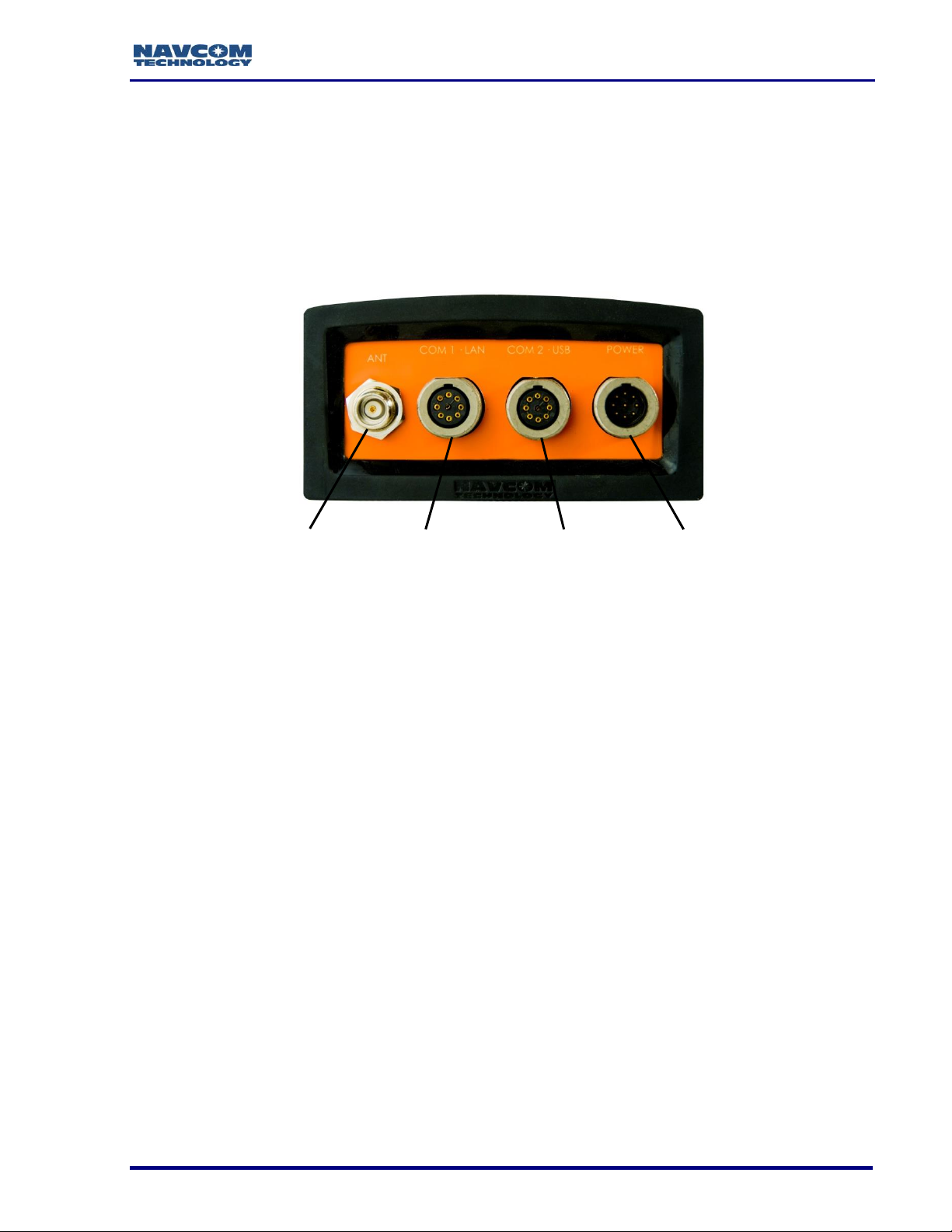
Figure 1: SF-3050 Rear View
Refer to Figure 1 for the steps below:
1. Use one of the two supplied data cables for communications:
DB9S cable (P/N 94-310260-3006LF): Connect the Positronic connector end to
COM2 - USB at the rear of the SF-3050. Connect the DB9S end to the PC.
Or
USB 2.0 Device cable (P/N 94-310266-3006LF): Connect the Positronic connector
end to COM2 - USB at the rear of SF-3050. Plug the USB plug end into the PC.
, Communication Ports, for details on the ports and Bluetooth connection.
2. Mount the supplied Rover, Base, or Airborne antenna. Locate the antenna in an area
with a 360 clear view of the sky.
Refer to Chapter 4/Antennae for additional considerations and restrictions.
3. Connect the supplied GNSS antenna cable
(P/N 94-310261-3012LF) to the GNSS antenna. Connect the other end of the cable to
the TNC connector, labeled ANT, at the rear of the SF-3050.
Refer to
2
Page 22
SF-3050 GNSS Product User Guide – Rev I
Table 21 for longer cable lengths.
4. Perform these steps to set up power:
5. Plug the supplied AC power cord (P/N 73-200002-0001LF) into the supplied Universal
AC/DC Power Adapter (P/N 82-020007-3001LF). The adapter operates on either 120
or 240 VAC power.
The purchase of a separate appliance cable may be necessary if the VAC
plug configuration needed is not the standard 2-prong American connector.
6. Connect the female Positronic connector end of the Power Adapter cable into the
male connector, labeled POWER, at the rear of the SF-3050.
7. Plug the AC power cord into an AC receptacle.
8. Press the front panel On/Off switch to turn on the SF-3050 (see Figure 82). All front
panel LEDs illuminate for a period of 3 to 5 seconds during power-up. The
Power/GNSS Status LED changes from Red to Green.
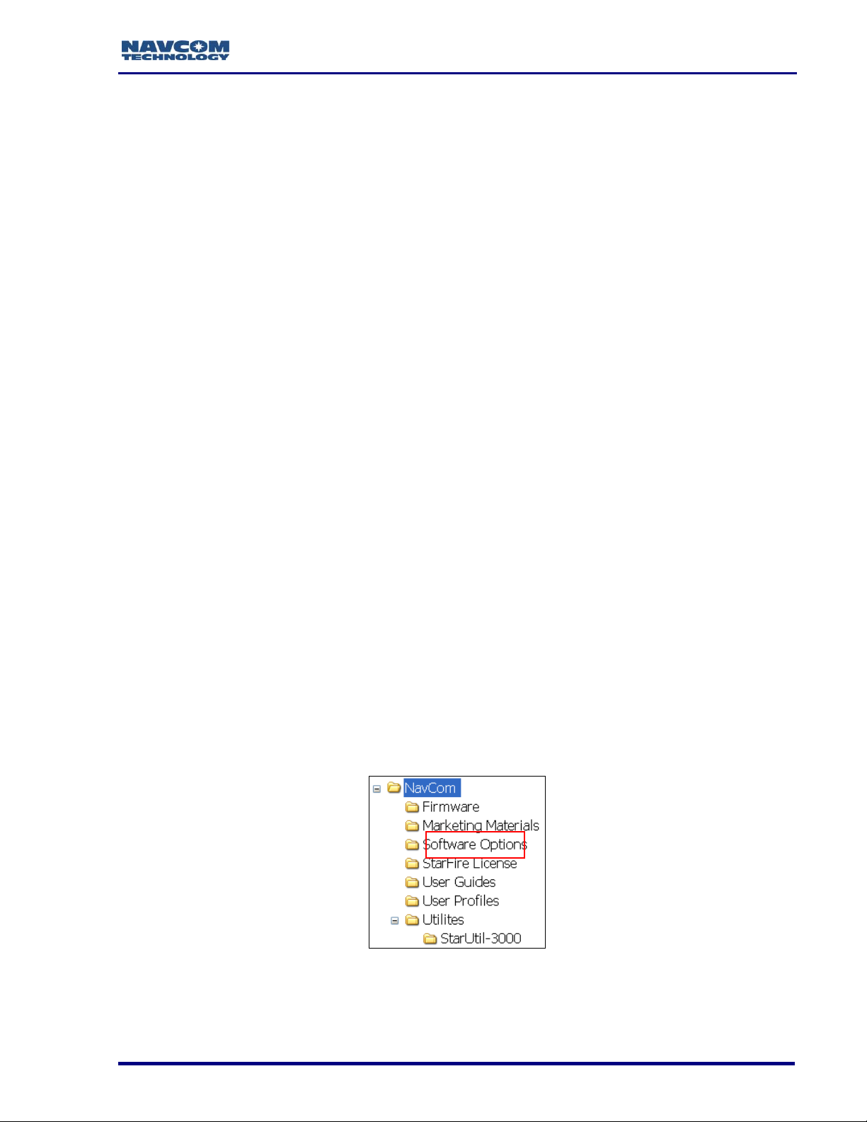
Save Folder/Files to PC
The SF-3050 Product Configuration USB Flash Drive includes:
Root Directory: Software Options File and StarFire License (if purchased)
NavCom Folder: Includes these sub-folders: Firmware, Marketing Materials,
Utilities, User Guides, User Profiles
(The contents of the NavCom folder are subject to change.)
9. Plug the SF-3050 Product Configuration USB Flash Drive into the PC.
10. Browse to the USB Flash Drive.
11. Save the Software Options File, StarFire License (if purchased), and NavCom folder
to the PC.
12. On the PC, create two folders in the NavCom folder for the Software Options File and
the StarFire License (see Figure 2).
Figure 2: NavCom Sub-Folders on PC
3
Page 23
SF-3050 GNSS Product User Guide – Rev I
Connections Button
Only Software Options and StarFire License files are sent via email. All
other files are available either on NavCom’s website or via
Customer Support.
Establish Communications
13. Browse to Navcom\Utilities\StarUtil 3000 on the PC (see Figure 2).
14. Ensure that these files are in the StarUtil 3000 folder: “StarUtil3000_v0,0,x.exe”
(program executable file), “navcomx1c45x3050.inf” (USB driver), 96-3120073001RevX_Sapphire TRM.pdf, and 96-310029-3001RevX_StarUtil3000.pdf.
The USB driver must be in the same folder as StarUtil 3000 for the USB
port to auto-recognize the SF-3050.
When the SF-3050 is first connected to the PC port, a Windows wizard
opens. Locate and install the “NAVCOMx1c45x3050.inf” file before starting
StarUtil 3000. Also, note the com port number once the install completes.
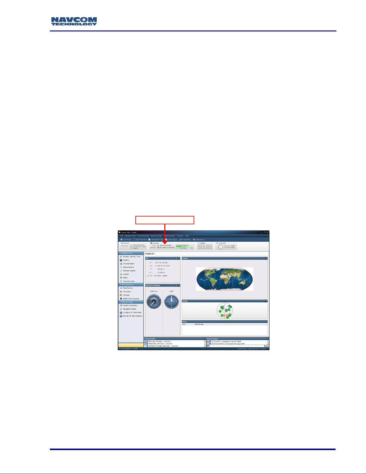
15. Double-click “Starutil3000_v0,0,x.exe” to open the program.
Figure 3: StarUtil 3000 – Main Window
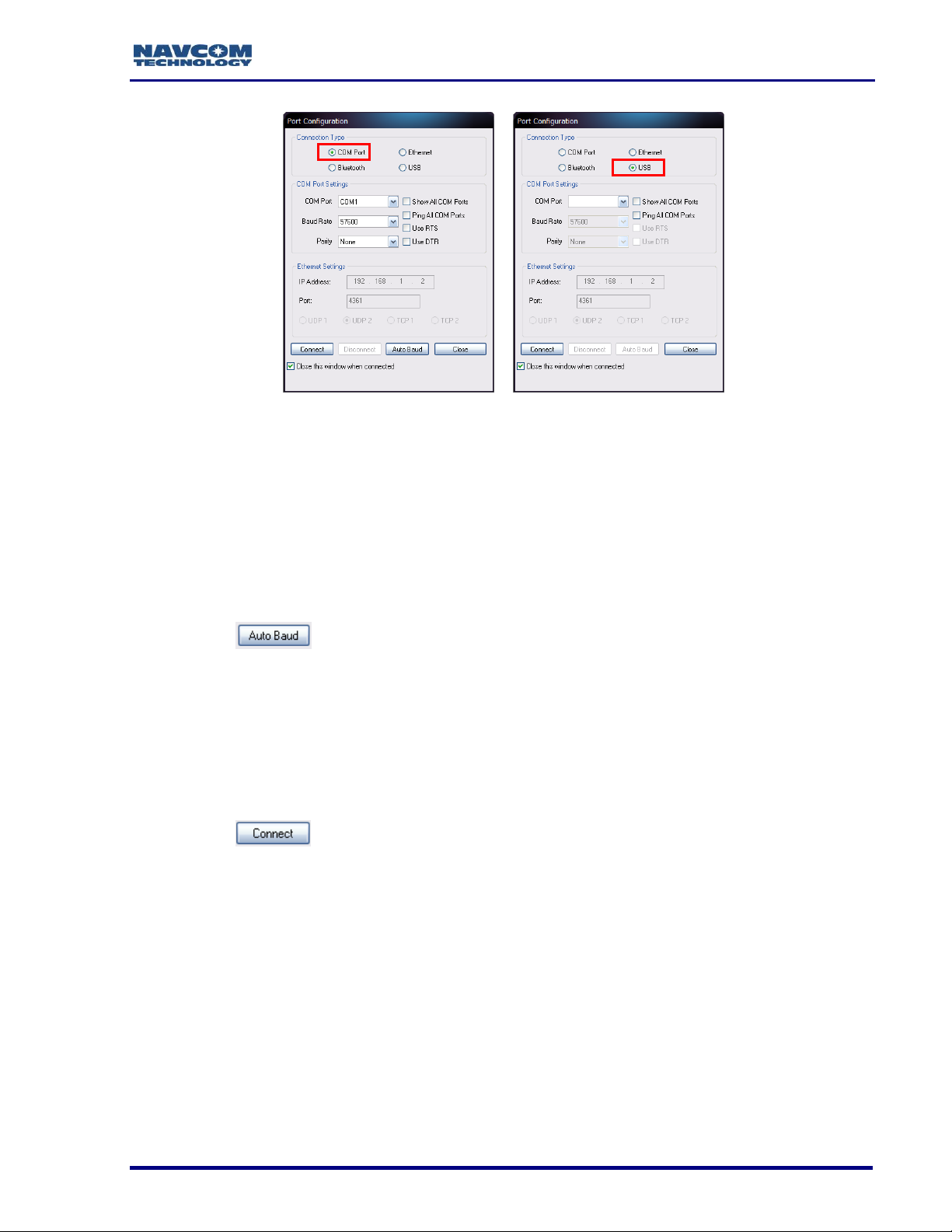
16. Click the Connections button to establish communications between the PC and the
SF-3050 (see Figure 3). The Port Configuration dialog box opens (see Figure 4).
Refer to Figure 4 for the steps below:
4
Page 24
SF-3050 GNSS Product User Guide – Rev I
COM Port Settings
USB Settings
Figure 4: Port Configuration
17. Set the appropriate options according to the Connection Type:
COM Port (on the PC):
COM2 (on the SF-3040)
Baud Rate: 57600 (keep the default)
Parity: None (keep the default)
Click to connect.
Or
USB (on the PC)
USB-COM1 (on the SF-3040)
Baud Rate: 57600 (keep the default)
Parity: None (keep the default)
Click to connect.
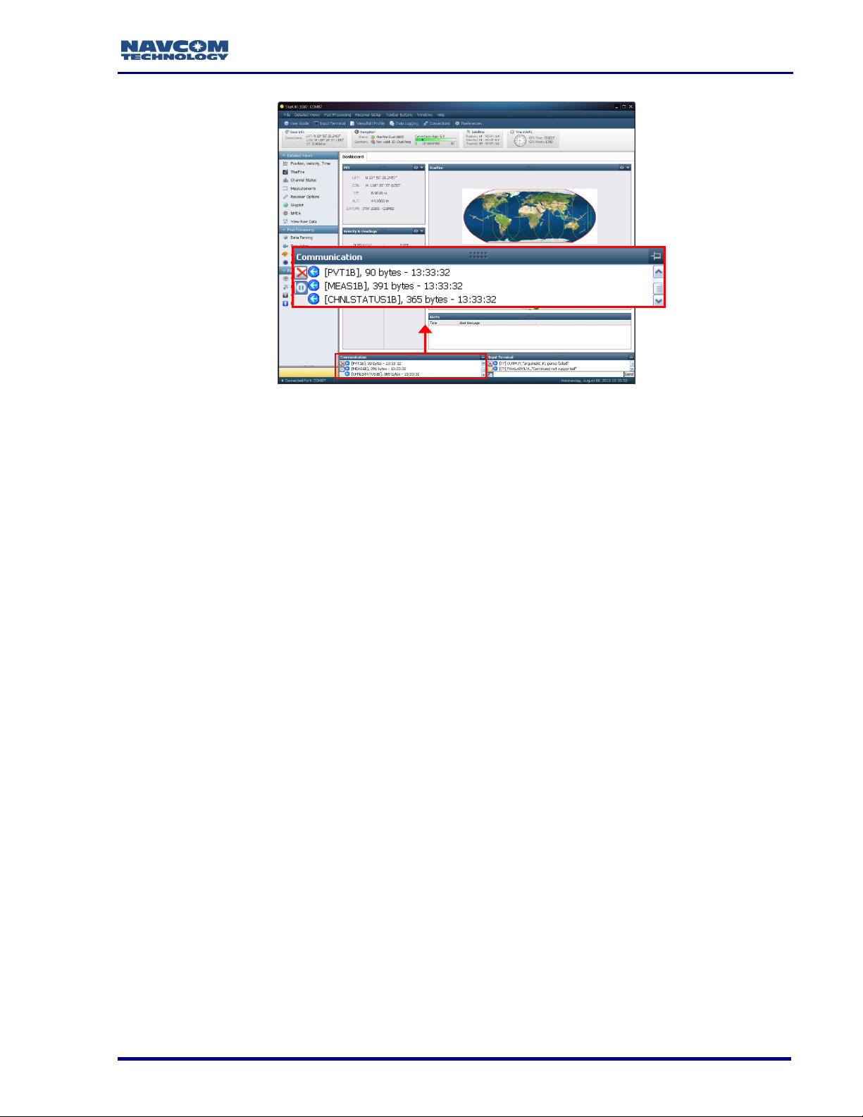
18. Verify that the SF-3050 is connected to the PC: Scrolling messages in the
Communication window indicate that a valid connection is established at the required
baud rate (see Figure 5).
5
Page 25
SF-3050 GNSS Product User Guide – Rev I
Figure 5: StarUtil 3000 Communication Window
A blue arrow indicates messages received by the GUI. A green arrow
indicates messages sent by the GUI.
COM Port Connection: Scrolling lines designated as “DATA” indicate a
connection is established but the baud rate is not correct (see Figure 6).
Reopen the Port Configuration dialog box.
6
Page 26
SF-3050 GNSS Product User Guide – Rev I
Firmware Info Window
Figure 6: Connection at Incorrect Baud Rate
For remote operation, connection to either Com 1 or Com 2 is highly
recommended as a backup to the Ethernet interface. The Com1 or Com 2
backup connection can be made via a cell modem, MOXA to Ethernet, etc.
Determine Current Firmware Versions
The user determines if the most current firmware is installed in the SF-3050. The version
of the installed firmware is important to ensure the proper operation of the receiver.
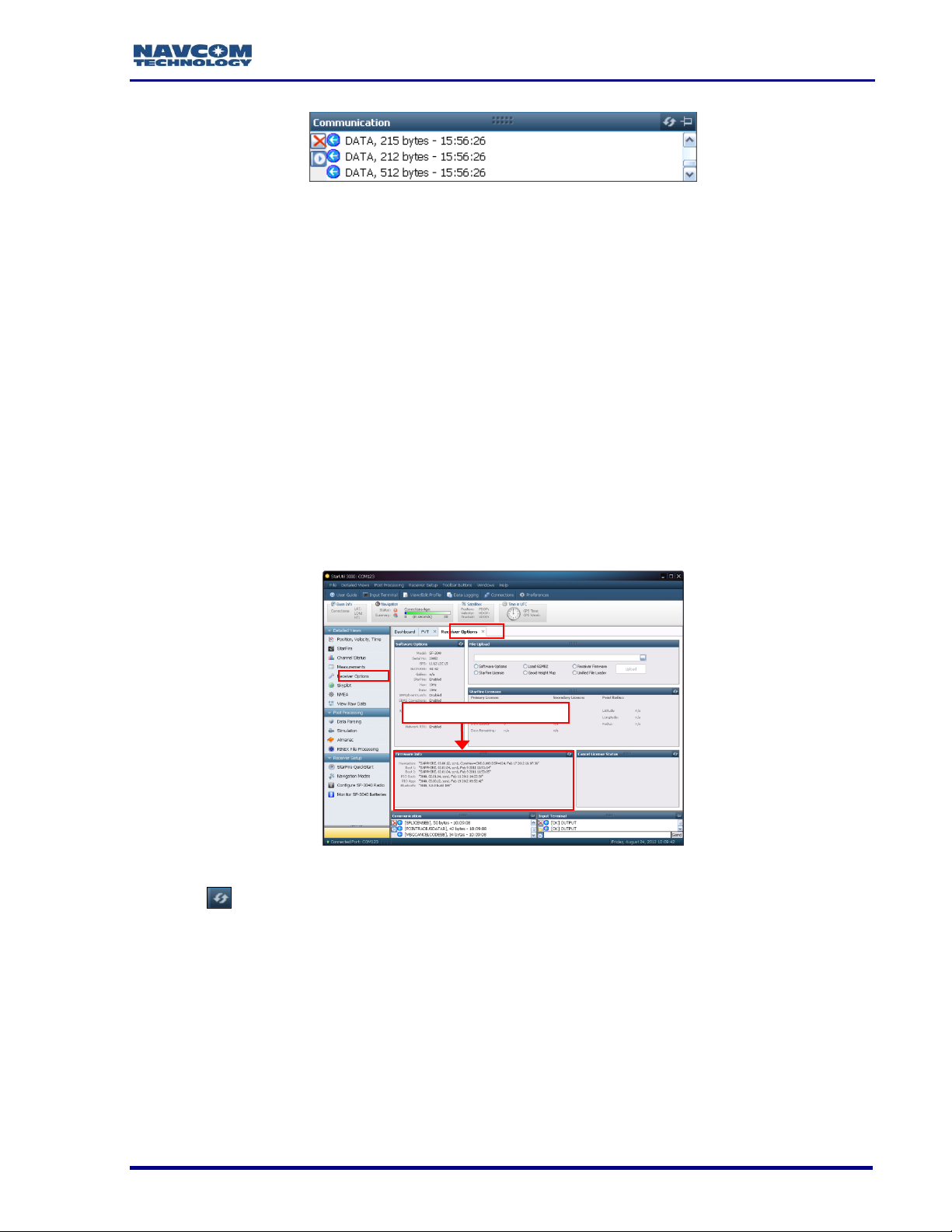
In StarUtil 3000, checking the contents of the Firmware Info window (see Figure 7) on the
Receiver Options tab is the easiest way to determine if the installed firmware is the most
current. An alternative method is to use the Input Terminal window (see Determine
Firmware Version via the Input Terminal, below).
19. Click Receiver Options on the Detailed Views menu to open the Receiver Options tab
(see Figure 7).
Figure 7: Access to Receiver Options Tab
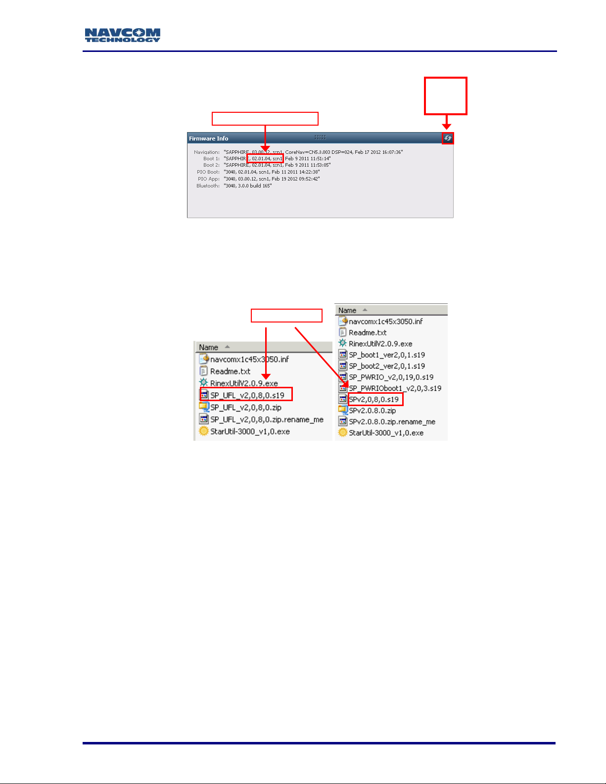
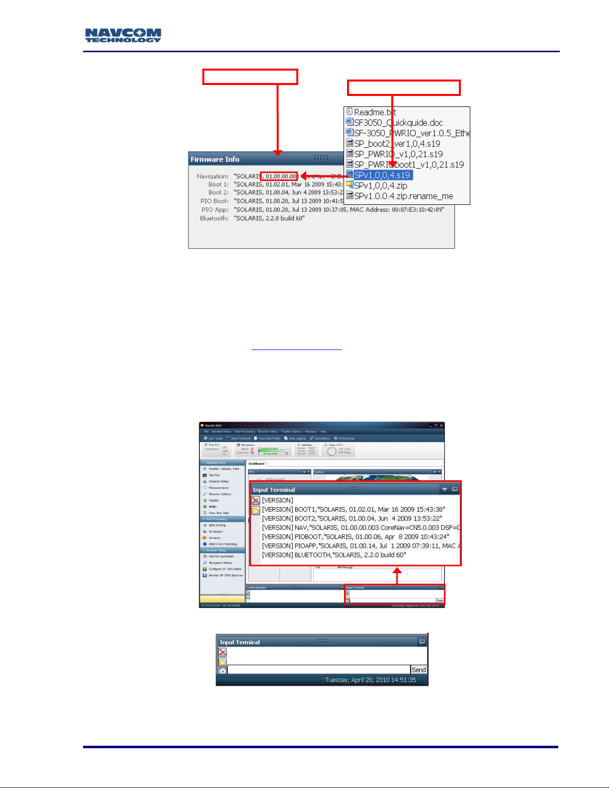
20. Click (refresh) on the Firmware Info window to view the current output data (see
Figure 8).
The firmware is identified by version number. For example, the NAV
firmware in the example below is version 01.00.00.003. Firmware
ensembles are always referenced to the Navigation Firmware Number.
7
Page 27
SF-3050 GNSS Product User Guide – Rev I
NAV Firmware Version
NAV Firmware
Click the
Refresh
Button
Figure 8: Example of Installed Firmware
21. Browse to the NavCom\Firmware folder on the PC (see Figure 2). The Firmware folder
is copied from the SF-3050 Product Configuration USB Flash Drive. It contains the
most current firmware (see example files in Figure 9). The firmware file extension is
*.s19.
Figure 9: Firmware Folder
Open the Readme.txt file for additional information.
22. Compare the current NAV Firmware version in the Firmware folder with the installed
version displayed in the Firmware Info window (see Figure 10).
In the example below, the NAV firmware in the Firmware folder is more
current than the installed firmware. As a result, the user must update the
NAV firmware in the receiver.
8
Page 28
SF-3050 GNSS Product User Guide – Rev I
Old NAV Firmware
Current NAV Firmware
Figure 10: Comparing Current and Installed Firmware
23. If the NAV firmware installed in the receiver is not the most current version:
Check the versions of the other firmware.
Write down all of the firmware that must be updated.
Go to the section below, Upload Firmware.
Determine Firmware Version via the Input Terminal
24. Locate the Input Terminal on the bottom right (see Figure 12).
Figure 11: Input Terminal – Firmware Versions
25. Click and drag the top edge of the Input Terminal window to enlarge it.
Figure 12: Input Terminal
9
Page 29
SF-3050 GNSS Product User Guide – Rev I
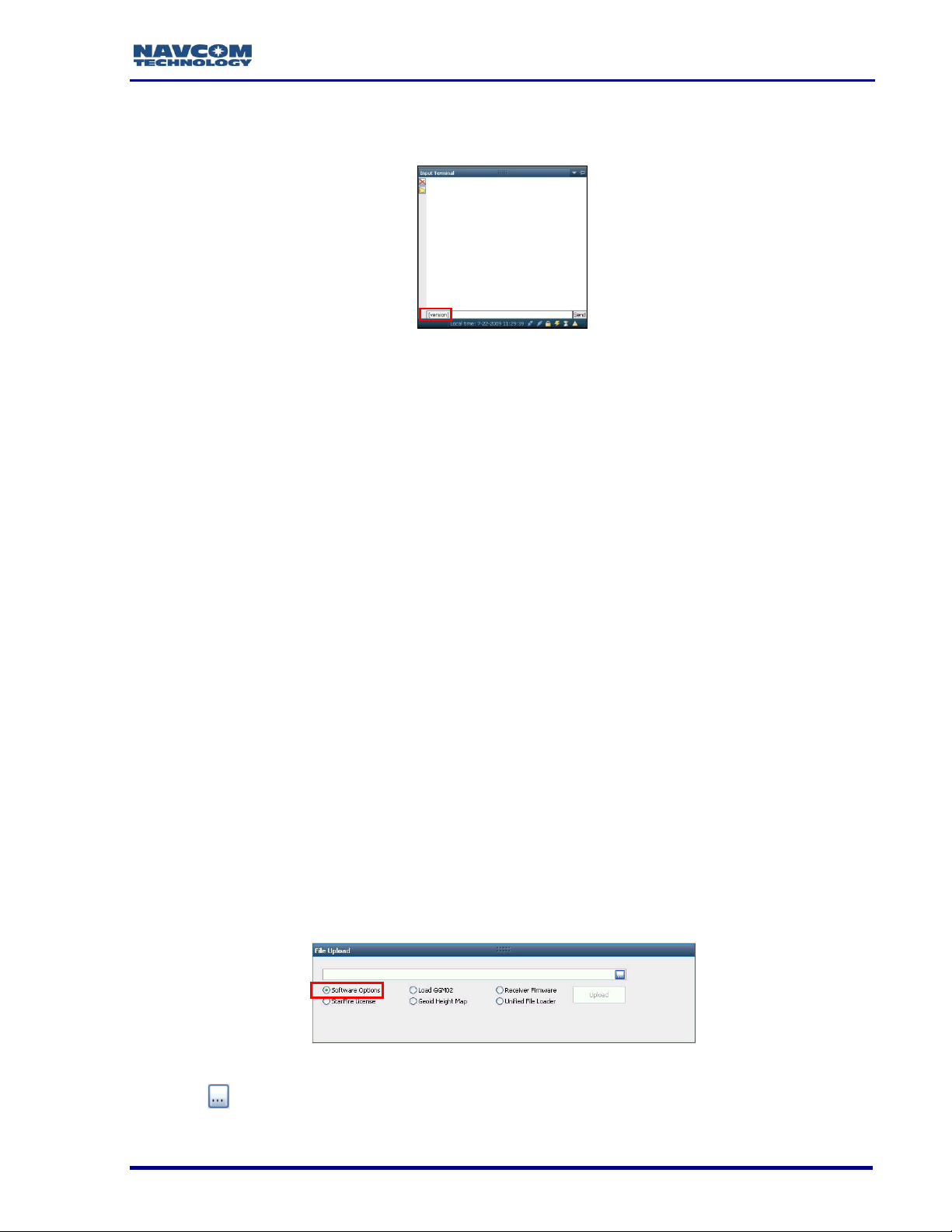
26. Type [VERSION] in the field at the bottom of the Input Terminal window (see Figure
13).
Figure 13: Version Command
27. Click the Send button on the Input Terminal. The receiver returns a list of the currently
installed firmware.
28. Browse to NavCom\Firmware on the PC (refer to Figure 2). The Firmware folder
contains the most current firmware. The firmware file extension is *.s19.
29. Compare the current NAV Firmware version in the Firmware folder with the installed
version displayed in the Input Terminal window (see Figure 12).
If the NAV firmware installed in the receiver is not the most current version:
Check the versions of the other firmware.
Write down all firmware that must be updated.
Upload Software Options
Software options may be purchased in a bundle and/or individually. The SF-3050
software bundles are SF-3050A, SF-3050G, SF-3050S, and
SF-3050M. Refer to Chapter 2/ Software Bundles for descriptions of the software options
in each bundle.
Software Options must be uploaded before uploading the StarFire License,
if purchased.
The receiver must be navigating at the time of the software options upload.
30. Select Software Options on the File Upload window (see Figure 14).
31. Click .
Figure 14: Software Options
10
Page 30
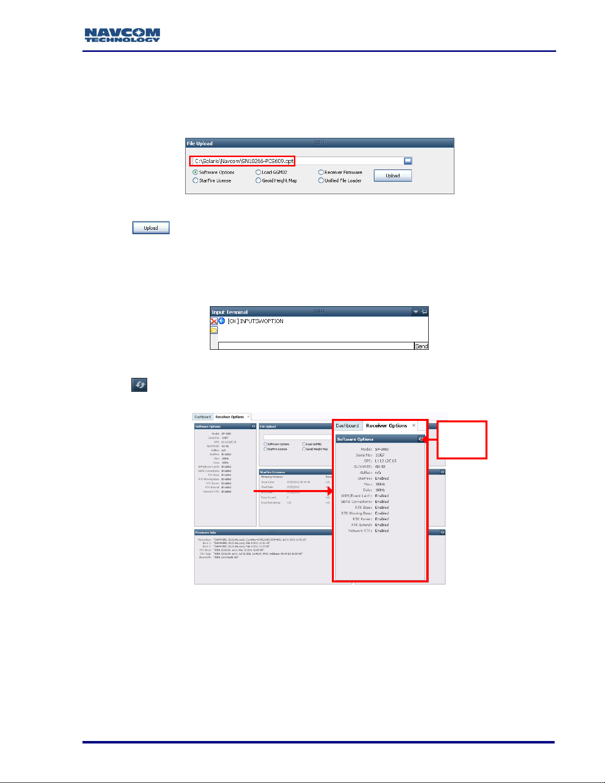
SF-3050 GNSS Product User Guide – Rev I
Click the
Refresh
Button
32. Browse to NavCom\Software Options on the PC. The Software Options file extension
is *.opt.
33. Select the Software Options file. The path to the file appears in the upload field (see
Figure 15).
Figure 15: Software Options Upload
34. Click . At the end of upload, a confirmation box opens. Click OK.
The Input Terminal window also displays the outcome of the upload (see
Figure 16). In the example below, the upload is successful. Refer to the
Sapphire Technical Reference Manual for detailed information on the
INPUTSWOPTION command (see Related Documents in the fore-matter).
Figure 16: Successful Software Options Upload
35. Click
uploaded software options are displayed (see Figure 17).
(refresh) on the Software Options window and check to ensure that all
Figure 17: Software Options Window
“StarFire: Enabled” indicates that the StarFire Software Option is loaded. It
does not indicate that a StarFire License is installed.
36. Do not close StarUtil 3000. Perform one of these steps:
If a StarFire License is purchased, go to the Upload StarFire License section.
If a StarFire License is not purchased, go to the Factory Default User Profile
section.
11
Page 31

SF-3050 GNSS Product User Guide – Rev I
The SF-3050 returns the entire list of loaded software options. However,
StarUtil 3000 does not display the entire list in the Software Options
window. Perform steps 55 through 58 to confirm the software uploaded to
the receiver.
37. Type the command [INPUTSWOPTION] on the Input Terminal window.
38. Click Send.
39. Highlight and copy the entire output.
40. Open any text editor (e.g., Microsoft Notepad) and paste the output there to verify that
all software options have been uploaded to the receiver.
If the above method fails to upload any of the purchased software options,
refer to the next section.
Upload Software Options via the Input Terminal
Perform steps 12 through 17 to upload software options via the Input Terminal.
41. Open the software option file in any text editing program (e.g., Notepad).
42. Locate the option code at the bottom of the file (e.g., 74C91E91 789FA173 8E70296A
3259B2E6).
43. Highlight and copy the option code.
44. Enter the command [INPUTSWOPTION] on the Input Terminal window and then
paste the option code: 74C91E91 789FA173 8E70296A 3259B2E6.
45. Click Send on the Input Terminal window. If the software options loaded successfully,
the Input Terminal window displays a confirmation message (see Figure 16).
46. To view all currently loaded software options, click (refresh) on the Software
Options window (see Figure 17).
Upload Firmware
The required PC Baud rate to upload firmware via the supplied DB9S cable
(RS-232) on COM2 is 57600 (default). This requirement does not apply to
the supplied USB 2.0 Device cable.
The receiver must be navigating at the time of the firmware upload.
Typically, if any firmware needs to be updated, it is NAV and PIOAPP.
Upload a Unified Firmware File
47. Click Receiver Options on the Detailed Views menu to open the Receiver Options tab
(see Figure 18).
12
Page 32

SF-3050 GNSS Product User Guide – Rev I
Figure 18: Receiver Options Tab
48. Select Unified File Loader on the File Upload window (see Figure 19).
Figure 19: File Upload – Unified File Loader Option
49. Click .
50. Browse to the NavCom\Firmware folder on the PC (refer to Figure 20).
Figure 20: Firmware Folder
51. Select the appropriate unified file to upload and click (see Figure 20).
52. The files to be uploaded are displayed on the Ready to Downline Load File dialog box
with their corresponding check boxes selected (see Figure 21). Select and deselect
files as necessary.
13
Page 33

SF-3050 GNSS Product User Guide – Rev I
Figure 21: Ready to Downline Load File
53. Click .
54. Once the firmware files are uploaded, the Finished with All Downline Loads dialog box
is displayed (see Figure 22).
Figure 22: Finished with All Downline Loads
55. Click .
56. Check the Firmware Info window (see Figure 8) to view the current versions of all
uploaded firmware.
If any file failed to load, go to Upload a Single Firmware File
Upload a Single Firmware File
57. Locate the File Upload window on the Receiver Options tab (see Figure 23).
14
Page 34

SF-3050 GNSS Product User Guide – Rev I
Figure 23: File Upload Window
58. Select Receiver Firmware on the File Upload window (see Figure 24).
Figure 24: Receiver Firmware Option
59. Click and the Load Receiver Firmware dialog box opens (see Figure 25).
Figure 25: Load Receiver Firmware
60. Click .
61. Browse to NavCom\Firmware on the PC (see Figure 26).
Figure 26: Firmware Folder
62. Select the appropriate firmware file.
Upload Boot files before application files if both types require updating.
Example Boot File: SP_boot1_ver2,0,1.s19
The format of the NAV firmware file is:
SPv + version number.s19
Example NAV File: SPv1,0,0,4.s19
15
Page 35

63. Set these options:
Baud Rate:
DB9S cable: Use the highest baud rate (i.e., 115200) unless the load fails. If
the load fails, use 57600.
USB 2.0 Device Cable: No selection is necessary (automatic connection
speed)
SF-3050 GNSS Product User Guide – Rev I
Figure 27: Settings for GNSS Firmware
Target:
Select SOLARIS to upload GNSS firmware (see Figure 27):
SP_boot1_[version number].s19
SP_boot2_[version number].s19
SPv[version number].s19
Or
Select SOLARIS PIO to upload PWRIO firmware (see Figure 28):
SP_PWRIOboot1_[version number].s19
SP_PWRIO_[version number].s19
Buffer Size: Do not set this option. The program automatically sets it.
Bootloader: Do not set this option. The program automatically sets it.
Force Load Firmware Without PING: Keep the default (unchecked).
Figure 28: Settings for PWRIO Firmware
16
Page 36

SF-3050 GNSS Product User Guide – Rev I
64. Click . An upload progress window opens (see Figure 29).
Figure 29: Progress Dialog Box
65. At the end of the upload, a confirmation box opens. Click OK.
66. Repeat steps 39 through 48 to upload another firmware file, if necessary.
67. Do not close StarUtil 3000. Continue to the next section.
Upload StarFire License
For the initial configuration, the StarFire license must be installed via data
cable. Subsequent renewals of the license are typically transmitted to the
receiver via radio broadcast. Refer to Over the Air StarFire Licensing for
details.
The receiver must be tracking GPS satellites and providing a valid position
solution at the time of the StarFire license upload to accept the license.
68. To confirm a valid position solution on the PVT tab/Navigation Status window, first
click Position, Velocity, Time (see Figure 30) on the Detailed Views menu to open the
PVT tab (see Figure 31 ).
Figure 30: Position, Velocity, Time Menu Item
17
Page 37

SF-3050 GNSS Product User Guide – Rev I
Click (refresh) on the Navigation Status window to ensure that the current
position solution is displayed (see Figure 31).
Figure 31: PVT Tab/Navigation Status Window
Figure 32: Navigation Modes Menu Item
69. Click Navigation Modes on the Receiver Setup menu to open the Set Navigation
Modes dialog box (see Figure 33).
Figure 33: Set Navigation Modes/StarFire ON
18
Page 38

SF-3050 GNSS Product User Guide – Rev I
Refer to Figure 33 for the steps below:
70. Click the Retrieve Settings From the Receiver button to retrieve the currently set
navigation modes from the receiver.
71. Select the ON radio button next to StarFire if StarFire is not enabled.
72. Click the Apply Changes to the Receiver button to enable StarFire navigation. Then
click Close.
73. Select StarFire License in the File Upload window on the Receiver Options tab (see
Figure 34).
Figure 34: StarFire License
74. Click .
75. Browse to NavCom\StarFire License on the PC. The StarFire License file extension is
*.lic.
76. Select the StarFire License file. The path to the file appears in the upload field (see
Figure 34).
77. Click the Upload button. At the end of the upload, a confirmation box opens. Click OK.
The Input Terminal window displays the outcome of the upload (see Figure
35). In the example below, the upload is successful. Refer to the Sapphire
Technical Reference Manual for detailed information on the
INPUTSFLICENSE command (see Related Documents in the fore-matter).
Figure 35: Successful StarFire License Upload
78. Ensure that the purchased StarFire License is loaded. These tabs provide license
information:
Receiver Options tab: StarFire Licenses and License Status windows
StarFire tab: License Info window
To open the StarFire tab, click StarFire in the Detailed Views menu (see
Figure 36).
19
Page 39

SF-3050 GNSS Product User Guide – Rev I
Figure 36: StarFire Menu Item
Confirm StarFire Navigation
79. Click Position, Velocity & Time on the Detailed Views menu (see Figure 30) to
determine if the receiver is navigating in StarFire mode. The PVT tab opens (see
Figure 37).
The receiver enters StarFire mode approximately 3 minutes after it is first
turned on; then the convergence period starts.
Figure 37: Nav Mode: StarFire Dual GNSS
The Nav Mode: StarFire Dual:GNSS: 3D: Dual freq in Figure 37 indicates
that the receiver is navigating in StarFire dual frequency with a 3D position
fix, which is very accurate.
How to Cancel a StarFire License
At the time [CANCELSFLICENSE] is input, the receiver must be tracking GPS satellites
and providing a valid position solution for the receiver to accept the license cancellation.
80. Input the [CANCELSFLICENSE] command on the Input Terminal window to cancel
the current StarFire license (see Figure 38).
Figure 38: Input Terminal – Cancel StarFire License
This action cancels the subscription to StarFire signal service. Users need
to contact their dealer or NavCom to replace the license.
20
Page 40

SF-3050 GNSS Product User Guide – Rev I
View the Cancel License Status window on the Receiver tab to confirm the StarFire
license cancellation. The window also displays a cancel code to affirm the cancellation of
the StarFire license before the expiration date
Factory Default User Profile
Further configuration is not necessary for this initial use of the SF-3050. The receiver is
pre-configured with a factory default user profile that includes settings for the various port
assignments/parameters, navigation parameters, and output message lists.
If the SF-3050 does not function properly, refer to these online tools:
Troubleshooting Guides
User Manuals
Contact the authorized dealer or NavCom Customer Support (refer to the beginning of
this chapter for contact information).
Upload User Profile (optional)
If desired, replace the factory default user profile with a predefined profile, or create a
profile. Refer to the StarUtil 3000 User Guide for detailed instructions.
Predefined user profiles are available in the Navcom\User Profiles folder
saved on the PC from the SF-3050 Product Configuration USB Flash
Drive.
Refer to Chapter 5/User Profiles in this guide for information on profiles.
Enable or Disable Receiver Tracking and/or Use of Select Signals and Frequencies
Receiver tracking of various signals and frequencies can be enabled or disabled.
Refer to the [TRACKINGMODE] and [NAVMEASUSE] commands in the Sapphire
Technical Reference Manual for detailed instructions on enabling and disabling the
tracking of and receiver use of various signals and frequencies. Also refer to
the StarUtil 3000 User Guide.
These commands are used primarily for engineering experiments or
receiver testing. They are not recommended for use in other applications.
Enable or Disable Receiver Use of Signals and Frequencies for Navigation
Receiver use of various signals and frequencies for navigation can be enabled or
disabled.
21
Page 41

SF-3050 GNSS Product User Guide – Rev I
Refer to the [NAVMEASUSE] command in the Sapphire Technical Reference Manual for
detailed instructions on enabling and disabling navigation signals and frequencies. Also
refer to the StarUtil 3000 User Guide.
This command is used primarily for engineering experiments or receiver
testing. It is not recommended for use in other applications.
Upload WebPages
1. Update firmware on SF-3050 receiver. The latest version of the software (v3.3.x.0 or
later) is required for this feature.
2. Determine the receiver’s IP address OR give it a static IP address by entering the
[ETHCONFIG] command in the Input Terminal screen.
Specify [ETHCONFIG]MANUAL to manually change the IP address.
Using [ETHCONFIG]AUTO will automatically set the IP address.
Figure 39: Input Terminal – [ETHCONFIG]
The IP address consists of the first four sets of three numbers separated
by periods. For further information on this command, see the Technical
Reference Manual.
3. Save the profile by entering [PROFILE]SAVEAS “XXX” in the Input Terminal screen
where the Xs indicate the name chosen for the profile.
Figure 40: Input Terminal – Save Profile
If the profile is not saved, the IP address will be lost the next time the
receiver is shut off and rebooted.
22
Page 42

SF-3050 GNSS Product User Guide – Rev I
4. Format the internal memory by entering [FSFORMAT]A:,DEFAULT in the Input
Terminal screen.
Figure 41: Input Terminal – Format Memory Card
The SF-3050 has a permanent 2GB SD card permanently installed. Once
this card is formatted, there is no need to reformat it. Reformatting the
memory after the 3.3.x.0 software update is necessary to repartition the
memory chip.
5. To load the Webpage files, select the File Upload screen under the Receiver Options
tab.
6. Click the Webpage Loader button and browse to the SolarisWebpagesv3.3.x/NCT file
on the USB stick.
Figure 42: File Upload – Webpage Loader
7. Select the NCT folder and click OK.
Figure 43: Webpage NCT Directory
The Webpage files are contained in the NCT directory. Loading the NCT
directory will load all the webpage files.
23
Page 43

SF-3050 GNSS Product User Guide – Rev I
8. Click the Load button to load the NCT directory.
Figure 44: Load Webpages NCT file
9. Enable the WebServer and choose webpage directory by entering the
[WEBCONTROL]ENABLE,NCT command in the Input Terminal screen. This will
ensure that the webpages in the NCT directory are enabled.
Figure 45: Input Terminal – Webcontrol
24
Page 44

SF-3050 GNSS Product User Guide – Rev I
Chapter 2 ..................................................................... Introduction
System Overview
GNSS Sensor System
The SF-3050 Global Navigation Satellite Systems (GNSS) sensor
delivers superior accuracy to the precise positioning community.
This unique receiver is designed with a robust and long-term
performance upgrade path to meet changing needs via software
upgrades. Increased functionality does not typically require the
costly purchase of additional hardware.
The SF-3050 software-enabled features, bundled or purchased individually, cover a wide
variety of applications.
The SF-3050 is uniquely suited for real-time applications in areas such as surveying,
machine control, precise positioning, and construction. The sensor delivers the required
millimeter measurement precision and fast update rates at low data latency. Depending
on the software bundle, the SF-3050 provides flexibility to be configured as a base station
or as a rover.
Superior interference suppression (both in-band & out-band), multipath mitigation, and
measurement accuracy are only a few of the sensor’s technological advances. The SF3050 GNSS engine incorporates several patented innovations advancing the existing
GNSS technology to the next generation. The receiver provides near optimal GPS P-code
recovery, providing a significant signal-to-noise ratio advantage over competing
technologies, among other benefits.
There are four software bundles: the SF-3050A, SF-3050G, SF-3050S, and SF-3050M.
Depending upon the bundle, this receiver provides, but is not limited to:
NavCom’s StarFire
(SBAS) for decimeter level position accuracy (post-convergence period). Refer to
Appendix C for detailed information.
1
Dependent on the bundle: Subscription and Software Option Required
RTK: This unique receiver is designed to integrate easily into Real-Time Kinematic
(RTK), field data verification, topographical surveys, and a wide variety of surveying
applications. The system resolves ambiguities at startup or on satellite reacquisition
typically within 2 seconds. The
SF-3050 delivers centimeter level position accuracy via external RTK2 correction
formats. The receiver is capable of NCT RTK/UltraRTK™, RTCM 2.3 and 3.1 (code
and phase), Network RTK, and CMR/CMR+ DGPS operating methods. The operating
software is also capable of supporting an external radio modem.
1
Network: A worldwide Satellite Based Augmentation System
2
Dependent on the bundle: Separate Software Option Required
Signal Reception: The SF-3050 GNSS engine includes a digital ASIC to handle high
speed signal processing. The sensor provides proven unparalleled performance in
25
Page 45

SF-3050 GNSS Product User Guide – Rev I
Rate
SF-3050 Bundles
A1 G S M Position, Velocity, and Time
1,5*Hz
Std
Std
Std
Std
10Hz
Opt
Opt
Opt
Std
25*Hz
Opt
Opt
Opt
Std
50, 100Hz
Opt
Opt
Opt
Opt
Raw Data
1, 5*Hz
Std
Std
Std
Std
10Hz
Opt
Opt
Opt
Std
25*Hz
Opt
Opt
Opt
Std
50, 100Hz
Opt
Opt
Opt
Opt
spite of adverse signal tracking conditions by incorporating the use of GPS (L1, L2,
L2C, L5), GLONASS (G1, G2), and SBAS (WAAS, EGNOS, MSAS, GAGAN) signals
(standard for most software bundles).
66 Signal Channels: Provides the ability to track multiple frequencies of satellites in
several constellations simultaneously. This allows for extended navigation in otherwise
adverse conditions for a single constellation. An additional channel is dedicated to
tracking StarFire signals.
The system includes a Rover, Base, or Airborne antenna, and interconnection
accessories outlined in Table 13.
Performance Upgrade Path
The SF-3050 is designed with a robust and long-term performance upgrade path to meet
changing needs via software upgrades. The following tables outline the standard and
optional features of each SF-3050 software bundle.
Table 1: Performance Upgrade Path – Position & Data Rates
1
Bundle A is not available in software prior to v. 2.0.22.0.
*5Hz is the default PVT and Raw Data Rate for software bundles G and S.
25Hz is the default PVT and Raw Data Rate for bundle M.
26
Page 46

SF-3050 GNSS Product User Guide – Rev I
Signals
SF-3050 Bundles
G S M
GPS
L1
Std
Std
Std
L2
Std
Std
Std
L2C
Std
Std
Std
L5
Std
Std
Std
GPS
G1
Std
Std
Std
G2
Std
Std
Std
Correction Source
SBAS
Std
Std
Std
StarFire1
Std
Std
Std
RTK
SF-3050 Bundles
G S M
RTK Base
Opt
Std
Opt
RTK Moving Base
Opt
Opt
Opt
RTK Rover
Opt
Std
Opt
RTK Extend
Opt
Opt
Opt
Network RTK1
Opt
Std
Opt
Table 2: Performance Upgrade Path – Signals
1
The StarFire software option is standard for software bundles G, S, and
M. It does not include a StarFire license, which must be purchased to use
the StarFire subscription service. See Glossary or Web site.
Table 3: Performance Upgrade Path – RTK
1
Dependent on bundle options
27
Page 47

SF-3050 GNSS Product User Guide – Rev I
SF-3050 Bundles
G S M
1PPS/Event
Opt
Opt
Std
Table 4: Performance Upgrade Path – 1PPS/Event
Accuracy
SBAS
When WAAS, EGNOS, MSAS, or GAGAN (RTCA/DO-229D compliant) SBAS correction
signals are used, the system provides <30cm 2D position accuracy.
System accuracy with WAAS, EGNOS, MSAS, or GAGAN signals is
subject to the quality and update rate of these publicly operated signals.
Refer to Related Standards/Publicly Operated SBAS Signals in the forematter for contact information regarding the organizations that implement
the RTCA/DO-229D standard.
See the Sapphire Technical Reference Manual (TRACKINGMODE
command) and the StarUtil 3000 User Guide for details on disabling
WAAS, EGNOS, and MSAS.
StarFire
The system provides <5cm position accuracy (post-convergence period) 1 when StarFire
correction signals are used.
RTK
The system provides immediate < 1 cm position accuracy when UltraRTK1 correction
signals are used:
L1, L2, L2G, L5, G1,G2 baseline:
< 40 km, 1 cm + 0.5 ppm)
Also applies to Moving Base RTK
1
Dependent on software bundle options
After RTK correction signals are received, the baseline determines how
long it takes to enter RTK mode. A rover close to the base enters RTK
mode almost immediately. For longer baselines, it may take a minute or
two. For L1/G1 RTK, antenna model selection is also a factor in ambiguity
resolution and time required to enter RTK.
Features (for All Software Bundles)
Output Data Rate
The SF-3050 GNSS receiver can output proprietary raw data at programmable rates from
<1Hz to predetermined rates up to 100Hz1 and Position Velocity Time (PVT) data at
programmable rates from <1Hz to predetermined rates up to 100Hz1 through the data
ports2 with less than 10ms latency. Accuracies are maintained as each output is
28
Page 48

SF-3050 GNSS Product User Guide – Rev I
independently calculated based on an actual GNSS position measurement, as opposed to
an extrapolation/ interpolation between 1Hz measurements.
The throughput capacity of the ports is limited by the Baud rate and the
byte size and number of messages output.
1
Dependent on software bundle options
2
Port dependent, refer to Communications Ports for details.
NCT Binary Proprietary Data
The sensor can output proprietary raw data containing information including (but not
limited to):
Satellite Ephemeris (EPHEM1B)
Satellite Almanac (ALM1B)
Raw Pseudorange Measurements (MEAS1B)
Position, Height, & Time (PVT1B)
Velocity & Heading (PVT1B)
Signal to Noise (CHNLSTATUS1B)
Channel Status (CHNLSTATUS1B)
Correction Data (mirror data; RTKSTATUS1B)
Event/Marker (EVENTLATCHA)
Measurement Quality (PVT1B and PSEUDORANGESTATSB)
These data can be integrated in real-time positioning applications or post-processed
against any number of software applications designed to handle NCT or RINEX raw data.
The Sapphire Technical Reference Manual, available on NavCom’s Web site, describes
the attributes of each of the input/output records (see Related Documents in the forematter).
NMEA-0183 Data
The SF-3050 is capable of outputting several standard NMEA-0183 data strings (see
Related Standards in the fore-matter) and several proprietary data strings. All data are
headed with $GN, except for MLA, which is headed with $GL. All header formats are
accepted (e.g., $GP, $GL). Proprietary data strings are denoted with a $PNCT header.
The Sapphire Technical Reference Manual provides additional controls for heading types
and message lengths for some NMEA messages. NMEA data complies with v.4.1 of the
standard in SF-3050 v.3.0.16 or later.
Standard
ALM – GPS Almanac Data
DTM – Datum Reference
GBS – GNSS Satellite Fault Detection
GFA– GNSS Fix Accuracy and Integrity
29
Page 49

SF-3050 GNSS Product User Guide – Rev I
(v.3.0.16 or later)
GGA – GPS Fix Data
GLL – Geographic Position – Lat /Lon
GNS– GNSS Fix Data (v.3.0.16 or later)
GRS – GPS Range Residuals
GSA – GNSS DOP & Active Satellites
GST – GNSS Pseudorange Error Statistics
GSV – GNSS Satellites In View
HDT – Heading Degrees True
MLA – GLONASS Almanac Data
RMC – Recommended Min. Specific GNSS Data
ROT – Rate of Turn
RRE – Range Residual Errors
(This command is not defined in NMEA 0183 Standard version 3.0.)
TTM – Moving Base / Rover RTK data
VTG – Course Over Ground & Ground Speed
ZDA – Time & Date
Proprietary (header $PNCT)
Described in the Sapphire Technical Reference Manual (see Related Documents in the
fore-matter)
DTM– Datum Reference for user-selected reference frame
GGA – GPS Fix with Field 14
GST – GNSS Pseudorange Error Statistics
MDE – Marginally Detectable Error
SET – Solid Earth Tide
Software Bundles
Software Options may be purchased in a bundle and/or individually.
The Software Options File contains all of the purchased Software Options, whether
purchased in a bundle or individually. The initial Software Options File must be uploaded
to the receiver to enable the functionality of the SF-3050. Later purchased software
upgrades are also provided in a Software Options File for upload.
SF-3050G
The SF-3050G is a multi-constellation,
StarFire-enabled2 GNSS receiver system for users that require high-availability,
worldwide, decimeter accuracy.
30
Page 50

SF-3050 GNSS Product User Guide – Rev I
Upgrade paths for higher data rates and other options make the SF-3050G ideal for many
Offshore Survey and Positioning applications:
Nautical Stationkeeping
Dynamic Positioning
Dredging and Offshore Construction
Deep Water Survey
2
StarFire Software Option is standard. StarFire subscription is required.
SF-3050S
Adding Base, Rover, and Network RTK2 to the feature- rich SF-3050G receiver, the SF3050S is a powerful engine for use in Land Survey applications where precision is vital.
The small form-factor, light weight (only 1.1 lb), and Bluetooth connectivity allow the
receiver to fit nicely into a backpack Land Survey system with only an external RF cable
to the
pole-mounted antenna. In addition, the built-in,
high-speed data ports (USB and Ethernet) enable high-speed data transfer or remote
communication to the receiver.
The SF-3050S sensor meets the needs of a large number of applications including, but
not limited to:
Topographical Surveys in Rough Terrain
High-Accuracy Data Collection for Post-Processing
Real-time Positioning Application
Dependent on software bundle
SF-3050M
With 25Hz data rate output, 1PPS, and Event Marker features standard, the SF-3050M is
a hard-working GNSS receiver targeted towards any application requiring high-precision
data at a high rate. Users with machine control and aerial survey applications will
appreciate the compact form-factor, powerful GNSS performance, and critical
coordination signals (1PPS and Event Marker).
The SF-3050M is ideal for vehicle mounting to suit a wide variety of machine guidance
and control applications:
Towed Implement Guidance
Construction Machine Control – Blade Control and Grading
Railway, Ship, and Aircraft Precision Tracking
Port Operations and Container Tracking
31
Page 51

SF-3050 GNSS Product User Guide – Rev I
Bluetooth
The SF-3050 GNSS receiver is Bluetooth capable in all software bundle configurations.
The Bluetooth module permits cable-less operation between the sensor and a Bluetooth
equipped controller. Wireless connectivity is provided within a range of 10 m (32 ft), and a
data rate of 230.4Kbps is supported, 10 Hz maximum. The Bluetooth module contains
Bluetooth certified components and is FCC and CE certified. Communications
performance is dependent on the user Bluetooth device used.
Refer to Chapter 3 for setup instructions via the supplied NavCom software utility, StarUtil
3000 or via the Input Terminal using the [BTSET] command.
Ethernet Connection
An Ethernet connection may be set up for the SF-3050 receiver. Refer to Chapter 2 of the
StarUtil 3000 User Guide and to the Sapphire Technical Reference Manual
[ETHCONFIG] and [ETHVCOM] commands for detailed instructions on configuring and
establishing an Ethernet connection.
32
Page 52

SF-3050 GNSS Product User Guide – Rev I
Antennae
The SF-3050 GNSS sensor must be ordered with the Rover, Base, or Airborne antenna.
Each antenna is described below.
Rover
The Rover integrated GNSS antenna
(PN: 82-001020-3001LF) tracks GPS (L1, L2, L2C, L5),
GLONASS (G1, G2), StarFire (L-Band differential corrections),
and SBAS (WAAS/EGNOS/MSAS/ GAGAN) signals. The
compact GNSS antenna has excellent tracking performance and
a stable phase center. This antenna is listed in the Antenna Calibration Values available
from the National Geodetic Survey (NGS) calibration table hyperlinked to this text, as
NAV-ANT3001R.
The robust housing assembly features a standard 5/8” BSW thread for mounting directly
to a surveyor’s pole, tripod, or mast and is certified to 70,000 feet, (see Specifications for
restrictions).
Base
The Base integrated GNSS antenna
(PN: 82-001021-3001LF) tracks GPS (L1, L2,
L2C, L5), GLONASS (G1, G2), StarFire (LBand differential corrections), and SBAS
(WAAS/EGNOS/MSAS/ GAGAN) signals. The
Base GNSS antenna is designed to reduce
multipath error to provide better RTK
corrections to the rover network. It has
excellent tracking performance and a stable
phase center. The NGS calibration table for
this product is available on the following link:
http://www.ngs.noaa.gov/ANTCAL/Antennas.jsp;jsessionid=3DE81666766F189AFA9D57
D343082098?manu=NavCom This antenna is listed in the NOAA GNSS Antenna
Calibration tables, as NAV-ANT3001B.The robust housing assembly features a standard
5/8” BSW thread to permanently install the antenna. It is certified to 70,000 feet (see
Specifications for restrictions).
33
Page 53

SF-3050 GNSS Product User Guide – Rev I
Airborne
The Airborne integrated antenna (PN: 82-001022-3001LF) tracks
all GNSS, WAAS/EGNOS/MSAS/GAGAN and StarFire signals.
The compact GNSS antenna has excellent tracking performance
and a stable phase center for GPS (L1, L2, L2C, L5), and GLONASS (G1, G2). This
antenna is listed in the NOAA GPS Antenna Calibration tables, as NCT-ANT3001A. The
robust housing assembly features a flat mounting surface with four mounting holes and a
downward facing TNC connector. This antenna is also certified to 70,000 feet, and is
TSO-C144 certified (see Specifications for restrictions).
Controller
The SF-3050 GNSS sensor is designed for use with an external controller solution
connected via one of two Positronic COM ports1 or Bluetooth.
This may be accomplished using a PC, Tablet PC, or Personal Digital Assistant (PDA)
and a software program that implements the rich control language defined for NavCom
GNSS products. Refer to the user guide of your controller solution for further information.
NavCom lists several application software solutions on our website:
http://www.navcomtech.com/Support/ApplicationSoftware.cfm
In addition, NavCom provides a Windows™ based software utility, StarUtil 3000, with the
receiver.
The StarUtil 3000 User Guide, P/N 96-310029-3001, is available on-line at
http://www.navcomtech.com/Support/DownloadCenter.cfm?category=manuals.
1
For initial configuration
34
Page 54

Included Items
1
SF-3050 GNSS Sensor (P/N 92-310413-3001LF)
2
SF-3050 GNSS Sensor (w/out Bluetooth) (P/N 92-310413-3003LF)
3
GNSS Antenna Cable, 12 ft (P/N 94-310261-3012LF)
4
Positronic 9-Pin Female Universal AC/DC Power Adapter 110220VAC, 12VDC, 1.50A. (P/N 82-020007-3001LF)
5
Positronic 9-Pin Male to DB9S (RS-232/RS-422/1PPS) Data Cable,
6 ft. (P/N 94-310260-3006LF)
6
Positronic 9-Pin Male to USB 2.0 Device Plug, 6 ft
(P/N 94-310266-3006LF)
7
Mounting Brackets, 2. (P/N 88-310442-3001LF)
8
Early Production Units:
Positronic 9-Pin Female Unterminated Power Cable Without Filter,
10ft (P/N 94-310262-3010LF) {Not Shown}
Later Production Units:
Positronic 9-Pin Female Unterminated Power Cable With Filter, 10ft
(P/N 94-310274-3010LF) {Not Shown}
9
SF-3050 Product Configuration USB Flash Drive. Contains: Software
Options file, Firmware file, User Profiles, User Guides, Brochures,
Software Utilities, Technical Papers, and if purchased, a StarFire
License file. (P/N 82-043000-0001) {Not Shown}
Important: Refer to Chapter 1 for steps to enable the functionality of
the SF-3050 via the USB flash drive.
10
Quick Start Guide (P/N 96-310033-3001) {Not Shown}
11
American 2-Pin AC power Cord, 10 ft
(P/N 73-200002-0001LF) {Not Shown}
SF-3050 GNSS Product User Guide – Rev I
Figure 46: SF-3050 Supplied Equipment
Table 5: Supplied Equipment
35
Page 55

SF-3050 GNSS Product User Guide – Rev I
1
Rover GNSS Antenna (P/N 82-001020-3001LF)
2
Airborne GNSS Antenna (P/N 82-001022-3001LF)
3
Base GNSS Antenna (P/N 82-001021-3001LF)
Figure 47: Rover, Base, and Airborne Antennae
Table 6: SF-3050 Antennae
The SF-3050 GNSS sensor must be ordered with the Rover, Base, or
Airborne antenna.
36
Page 56

SF-3050 GNSS Product User Guide – Rev I
Applications
The SF-3050 GNSS receiver meets the needs of a large number of applications.
Depending on the purchased software bundle or individual options, the applications
include, but are not limited to:
Offshore
Nautical Stationkeeping
Dynamic Positioning
Dredging and Offshore Construction
Deep Water Survey
Machine Control and Vehicle Navigation
Towed Implement Guidance
Construction Machine Control – Blade Control and Grading
Railway, Ship, and Aircraft Precision Tracking
Port Operations and Container Tracking
Land Survey and GIS
Boundary Survey
Topographical Surveys in Rough Terrain
Construction Site Stake-out
High-Accuracy Data Collection for Post-Processing
Hydrographic Survey
Military Applications
Non-Weaponized Military Positioning Applications
Unmanned Systems
Oceanographic Survey and Research
Specialty Applications
Aerial – Photogrammetric Survey
High-Value Asset Location and Tracking
Positioning in Mining Applications
Continuously Operating Reference Stations
Structural Monitoring
Real-time Positioning Applications
OEM Integration
NavCom lists several application software solutions on our website:
http://www.navcomtech.com/Support/ApplicationSoftware.cfm
Unique Features
The SF-3050 GNSS sensor has many unique features:
Performance Upgrade Path
The SF-3050 is designed with a robust and long-term performance upgrade path to meet
changing needs via software upgrades. Increased functionality does not typically require
37
Page 57

SF-3050 GNSS Product User Guide – Rev I
1
Dependent on Bundle Options: Subscription and Software Option Required.
the costly purchase of additional hardware. The SF-3050 software-enabled features,
bundled or purchased individually, cover a wide variety of applications.
StarFire
The ability to receive NavCom’s unique StarFire1 correction service is fully integrated
within each unit (no additional equipment required). StarFire has several performance
levels. Modes include: GPS, GNSS, or LP (see Specifications). A single set of corrections
are used globally enabling a user to achieve sub-decimeter level positioning accuracy
without the need to deploy a separate base station, thus saving time and capital
expenditure.
StarFire position outputs are referenced to the ITRF-2008 datum (default) and can be
steered to WGS-84.
StarFire Over IP
StarFire corrections can also be received via the internet (requires v3.2.10 or later
firmware). This feature allows the user to request messages from an independent
StarFire server/caster by means of Ethernet interface. The user can select four mount
points and can choose between three data delivery rates for maximum reliability.
Over The Air StarFire Licensing
Over The Air StarFire Licensing is the easiest way to install a StarFire license. The
installation of a purchased license is accomplished via radio broadcast. Over The Air
StarFire Licensing is especially convenient for receivers in remote locations in the field.
Web Server
The Web Server feature allows the user to access positioning information and control the
receiver via a standard web browser (requires v3.3.7 or later firmware). Each receiver
comes with a unique IP address that can be accessed from any computer using Firefox,
Chrome, Safari or Internet Explorer. Easily accessible web pages can be used to view
satellite data and configure a variety of functions.
NCT RTK/UltraRTK
The RTK/UltraRTK algorithm developed by NavCom provides fast initialization and the
NCT ultra compact binary data format for RTK/UltraRTK ensures robust data throughput.
The SF-3050 is capable of outputting or accepting legacy 0x5B (RTK) or 0x5E (UltraRTK)
binary formats. Refer to the TRM for more details (see Related Documents in the forematter).
Positioning Flexibility
The SF-3050 is capable of using WAAS, EGNOS, MSAS, GAGAN (RTCA/DO-229D
compliant) code corrections via two internal Satellite Based Augmentation System
(SBAS) channels. The SF-3050 automatically configures to use the most suitable
correction source available and changes as the survey dictates (this feature can be
overridden).
RTK Extend™
RTK Extend (separate software option required) enables continuous real-RTK/RTK level
38
Page 58

SF-3050 GNSS Product User Guide – Rev I
positioning accuracy during radio communication outages by utilizing NavCom’s global
StarFire corrections.
Traditionally, when an RTK rover loses communication with the base station, it is unable
to provide centimeter position updates for more than a few seconds, resulting in user
down-time and reduced productivity. With RTK Extend, a NavCom StarFire receiver
operating in RTK mode can transition to RTK Extend mode and maintain centimeter level
positioning during communication loss for up to 15 minutes. RTK Extend allows more
efficient and uninterrupted work, enabling focused concentration on the work rather than
the tools.
RTK Extend is a unique patented technique, not available on any other manufacturer’s
receivers.
Multi-Format RTK
Refer to Appendix E, Base Network RTK Configuration, in the Sapphire Technical
Reference Manual for detailed instructions.
User-Defined Datum
Users can check the current datum (a reference surface to be used in defining the 3D
coordinates of a position) or set a specific datum to be used as the position for all PVT
data output. Refer to the Sapphire Technical Reference Manual and the StarUtil 3000
User Guide for detailed instructions on the use of the [DATUM] command.
Heading
The SF-3050 heading system consists of two SF-3050 receivers connected via a serial
cable. Each receiver’s antenna is located on the platform at the maximum possible
separation. One of the units is configured as a moving base and computes its position 10
times a second using any available augmentation signal. The moving base outputs
position and RTK measurement corrections to the other unit, which is configured as a
heading rover. The heading rover computes the heading looking from the base antenna
to the rover antenna and outputs the heading and position of both antennae up to a rate
of 10 Hz. Applications include construction equipment such as excavators and marine
applications such as dredging.
Coordinated Machines
An SF-3050 configured as a moving base is located on a reference platform. An SF-3050
configured as a rover is located on one or more additional platforms. All of the SF-3050
rovers are connected to the moving base via a wireless communication link. The moving
base computes its position 10 times a second using any available augmentation signal.
The moving base outputs position and RTK measurement corrections to the rovers. The
rovers compute the range and bearing to the moving base and output the range and
bearing, plus their position and the position of the moving base, at up to 10 times a
second. Applications include those requiring the relative positions of two or more moving
platforms, such as leader-follower vehicle applications or the relative positions of planes
or marine vessels.
Data Sampling
GPS (L1, L2, L2C, L5), GLONASS (G1, G2), and SBAS (WAAS, EGNOS, MSAS,
GAGAN) raw measurement data is up to 5Hz in the standard configuration for the SF-
39
Page 59

SF-3050 GNSS Product User Guide – Rev I
3050G and SF-3050S. An optional upgrade allows 10, 25, 50, and 100Hz raw
measurement data via high speed ports.
For the SF-3050M, the raw measurement data is up to 25Hz in the standard
configuration, with the optional upgrade of 50 and 100Hz.
The PVT (Position, Velocity, & Time) data is output at up to 5Hz in the standard
configuration for the SF-3050G and SF-3050S. An optional upgrade allows 10, 25, 50,
and 100Hz position updates for highly dynamic applications.
For the SF-3050M, the PVT data is output at up to 25Hz in the standard configuration,
with the optional upgrade of 50 and 100Hz.
Internal Memory
See the Sapphire Technical Reference Manual and the StarUtil 3000 User Guide for
detailed instructions on utilizing the SF-3050 internal memory flash drive.
Control of Power Consumption
Power consumption may be immediately reduced on the SF-3050 by disabling signals, as
necessary, using the [TRACKINGMODE] command. Refer to the Sapphire Technical
Reference Manual for instructions on using this command.
Continuously Operating Reference Station (CORS) Support
When optioned as an RTK Base Station, the SF-3050 is capable of computing and
outputting RTK message streams in multiple formats and raw satellite measurement data
for post-processing simultaneously. All message formats can be output on one of the
high-speed USB or Ethernet ports, or messages can be distributed among any of the
eight user ports. The following is an example of a real world application:
Com 1: NavCom proprietary corrections (x5B, x5C, etc.); transmit via 900 or 400MHz
radios
Com 2: CMR+; transmit via 900 or 400MHz radios
USB: Command and Control (StarUtil Interface)
Bluetooth: Command and Control (StarUtil Interface)
Ethernet Port 1: Command and Control (StarUtil Interface)
Ethernet Port 2: RTCM v2.3
Ethernet Port 3: CMR+
Ethernet Port 4: RTCM v3.1 (can include Ntrip)
Refer to the Sapphire Technical Reference Manual, Appendix E, for RTK operation
information.
For IGS or similar permanent Base applications, NavCom offers a Choke Ring antenna
option to significantly reduce multipath errors on signal reception.
NTRIP Support
The generation of differential GPS correction data is usually done directly on the GPS
receiver of a reference station, but this data can also be derived from observations
40
Page 60

SF-3050 GNSS Product User Guide – Rev I
obtained by networked reference stations. The combined data stream is then fed into a
network computer and made available on the Internet.
Refer to Appendix E, RTCM Internet Protocol (NTRIP).
Also see the [NTRIPCLIENT], [NTRIPCONFIG], and [NTRIPSERVER] commands in the
Sapphire Technical Reference Manual for detailed instructions.
GNSS Performance
The SF-3050 utilizes NavCom’s Sapphire GNSS engine, which incorporates several
patented innovations. Sapphire’s industry leading receiver sensitivity provides more than
50% signal to noise ratio advantage over competing technologies. This results in
improved real time positioning, proven through independent tests, when facing various
multipath environments.
Rugged Design
Units have been tested to conform to MIL-STD-810F for low pressure, solar radiation,
rain, humidity, salt-fog, sand, and dust. In addition, the unit is IP certified to the IP67 level
(compliant only when cables are connected).
The SF-3050 is also certified1 to comply with the relevant type approval procedures for
marine equipment of the Marine Equipment Directive (MED) 96/98/EC.
The rugged design of the SF-3050 system components provides protection against the
harsh environments common to areas such as construction sites, offshore vessels, and
mines. In some extreme shock and vibration applications, additional isolation hardware
may be required.
1
Requires use of NavCom’s supplied AC/DC converter.
41
Page 61

SF-3050 GNSS Product User Guide – Rev I
Chapter 3 ...................................................................... Web Server
This chapter details the use of the Web Server, the internet-based interface between the
SF-3050 and the user. This interface can be used instead of the StarUtil software if
desired.
WebServer pages can be viewed using several different browsers and vary
slightly based on the browser in use. Optimal results are obtained by using
Mozilla Firefox® or Google Chrome®. The illustrations in this chapter were
made using Google Chrome® as the browser.
Accessing the WebServer
Each SF-3050 receiver comes with a unique IP address. See Chapter 1 setup Web
Server. Typing the IP address into the Address box on the browser page will open a
security screen.
Figure 48: Windows Security Screen
A default user name and password is pre-programmed into the receiver’s memory
consisting of the following:
User Name: admin
Password: admin
This default user name automatically has ADMIN level access, which enables the user to
view all webpages including the Input Terminal page and the Manage Accounts page.
The user name and password for this default account can be changed in the Manage
Accounts page. The password can be changed in the Change Password page. New user
names, passwords and access levels (USER and TECH) can be added in the Manage
Accounts page.
This ADMIN account cannot be deleted or given a different access level in
the Manage Accounts page.
42
Page 62

Welcome Page
SF-3050 GNSS Product User Guide – Rev I
Figure 49: Welcome Page
The Welcome Page shows the following information:
Serial Number of the SF-3050 receiver
Firmware with version and date installed
Bluetooth version
Receiver Location Bar
A bar across the top of the screen displays the current position and status of the receiver.
This status is continually updated as new information is received from the satellites.
Figure 50: Location Bar
This bar appears across the top of every WebPage.
A Logout button is located in the upper right hand corner of the bar. The Logout function
will allow the user to perform the following:
Close out the web page feature without having to exit the browser.
Log out of one user name and access level and log in with another user name and
access level.
Access another internet webpage while the webserver webpage is still active.
43
Page 63

SF-3050 GNSS Product User Guide – Rev I
Main Menu
The main menu located on the left hand side of the welcome page shows links to the web
pages available on the WebServer. Click each heading to open the desired menu.
Figure 51: Welcome Page with Expanded Menu Bar
Welcome Page
Messages
PVT Data
Channel Status
Measurements
StarFire Status
StarFire Almanac
NMEA View
Skyplot
Configuration
Schedule Messages
NTRIP Config
Navigation Modes
RTK Mode
Self Survey
Antenna
44
Page 64

Utility
View/Load Profile
Firmware Update
Data Logging
Almanac Loader
Options and License
Change Password
Manage Accounts
Input Terminal
Help
Messages
PVT Data
SF-3050 GNSS Product User Guide – Rev I
The PVT Data screen provides a quick view of the receiver’s current position, velocity,
estimated error, navigation status, antenna offset and solid earth tide.
Figure 52: PVT Screen
The PVT screen shows the following information:
Position: Displays altitude, Longitude, Height, Altitude and Datum. Datum displays the
selected reference model.
Velocity: The speed over ground and direction of travel (true, not magnetic).
Navigation Status: Displays Summary Nav Status, Nav Mode, Constellation (either
GPS or GPS/GLONASS), StarFire Engine Mode, StarFire Source, Correction Age and
Age Limit
Summary Nav Status: Various indications of nav status, including Nav valid,
Nav invalid, No Doppler, Doppler Used, etc.
45
Page 65

SF-3050 GNSS Product User Guide – Rev I
Nav Mode: Various indications of nav mode, for example, StarFire
Dual:RTG; 3D: Dual freq; Non differential: 3D: Dual freq, etc.
Constellation: GPS or GPS/GLONASS
Correction Age: The age of the current aided navigation correction in
seconds. This value changes depending on the correction source and the
correction interval. A few seconds is okay, but many seconds indicate the
fix is degrading over time, and becoming less and less accurate.
Age Limit: The maximum amount of time in seconds the received correction
will be used in case of an outage or drop in the reception of corrections.
The maximum age limit is 100 seconds. The default is 300 seconds for
SBAS (WAAS, EGNOS, MSAS, GAGAN) and RTCM type 1 or 9. The
default is 1200 seconds for RTG (StarFire).
Error Estimate
Position FOM: The position Figure Of Merit is the estimated uncertainty in
the navigation solution. FOM is the same as the One sigma error estimate.
Refer to the Sapphire Technical Reference Manual (see Related
Documents in the forematter).
Time FOM: 10x TDOP
DOP: Dilution of Precision. A class of measures of the magnitude of error in
GPS position fixes due to the orientation of the GPS satellites with respect
to the GPS receiver. There are several DOPs to measure different
components of the error: GDOP (Position and Time), PDOP (Dimensional
Position), HDOP (Horizontal Position), VDOP (Vertical Position), and TDOP
(Time).
Antenna Offset: If applicable.
Solid Earth Tide: Displays earth’s deformation vector in three dimensions, north, east
and vertical.
Channel Status
The Channel Status screen provides instantaneous diagnosis of signal quality and
performance for the tracked satellites in three constellations: GPS, GLONASS, and
SBAS.
46
Page 66

SF-3050 GNSS Product User Guide – Rev I
Figure 53: Channel Status Screen
The data below is displayed for each channel on the GPS, GLONASS, and SBAS
windows. Differences between the constellations are identified.
PRN: The satellite number assigned to each channel.
GPS: The valid range is 1-32. (The receiver allocates the range of 1-37, with 33-37
reserved for expansion.)
GLONASS: The valid range is 1-24.
SBAS: The valid range is 120-138.
AZ: Azimuth. The horizontal angle of the satellite relative to the receiver position in
reference to North ranging from 0 (360) to 359 degrees.+
EL: Elevation. The vertical angle of the satellite off the horizon ranging from 0 degrees
to a zenith of 90 degrees.
CH (Code Type): The channel number of the receiver, within a range of 0 – 53. The
code types tracked by the channel are:
GPS: L1CA, L1P1, L2, L2C, and L5 based on the [TRACKINGMODE]
command settings
GLONASS: G1C, G2C, G1P, and G2P based on the [TRACKINGMODE]
command settings
SBAS: L1CA (These code types are displayed, but don’t apply: L1P1, L2,
L2C, and L5.)
ST: Status. The channel tracking status of each channel. The status code LOCK
means the channel is locked up for measurement type and satellite, measurements
are ready.
C/No: Signal-to-Noise. The signal-to-noise value varies depending on satellite
elevation and any obstructions between the satellites and the receiver. The typical
47
Page 67

SF-3050 GNSS Product User Guide – Rev I
performance range for C/N0 for all displayed L1/G1 (GPS/GLONASS) channels is
46dB to 52dB, although higher and lower values can be noted. The C/N0 for C/A and
G1 is the same. G2 is similar to P2 C/No (6 [dB-Hz] less than G1). L1P is 3dB lower
than CA, and L2 is 6dB lower than CA. A value > 50 is typical of a satellite with 50º
elevation or higher and a clear view of the sky.
CR: Costas Ratio: the estimate of maximum error in phase measurement. The Costas
Ratio value has a range of 100 to -100.
AL: Almanac. Y = almanac is available for the position solution. N = no almanac
TM: The search timeout; i.e. the number of seconds before the search for the satellite
is stopped.
Measurements
The MEAS1B output stream contains raw measurement data collected from the receiver’s
tracking channels. Measurements are tracked from both the GPS/SBAS constellation and
the GLONASS Constellation. Raw measurements can be post-processed to achieve
precise point positions.
Figure 54: Measurements Screen
GPS/SBAS Constellation
PRN: The satellite number assigned to each channel.
GPS: The valid range is 1-32. (The receiver allocates the range of 1-37,
with 33-37 reserved for expansion.)
SBAS: The valid range is 120-138.
CA (m): Coarse / Acquisition code. The number of meters (range measurement) to the
satellite.
L1-CA (m): The L1 frequency minus the CA measurement.
48
Page 68

SF-3050 GNSS Product User Guide – Rev I
P1-CA (m): The P1 pseudorange minus the CA measurement.
P2-CA (m): The P2 pseudorange minus the CA measurement.
L2-CA (m): The L2 frequency minus the CA measurement.
L2C-CA (m): The L2C frequency minus the CA measurement.
L2C(code)-CA (m): The L2C code measurement minus the CA measurement.
CA C/No (dB): Carrier-to-noise ratio. The signal strength indictor.
P2 C/No (dB): The P2 measurement Carrier-to-noise ratio. The signal strength
indictor.
L1CA Doppler (c/s): The representation (in cycles per second) of the motion toward or
away from the L1CA signal.
L2P Doppler (c/s): The representation (in cycles per second) of the motion toward or
away from the L2P signal.
L5Q-CA (m): The L5Q measurement minus the CA measurement.
L5-CA (m): The L5 measurement minus the CA measurement.
L5Q C/No (dB): The L5Q measurement Carrier-to-noise ratio. The signal strength
indictor.
L5Q Doppler (c/s): The representation (in cycles per second) of the motion toward or
away from the L5Q signal.
Normally, the SF-3050 receiver locates and tracks SBAS satellites at run-time,
periodically building a list of the satellites that will contribute to the navigation solution.
However, a user can create a fixed list of SBAS satellites to track. Creating a list that
does not contain any visible satellites disables the use of SBAS corrections in the
navigation solution.
GLONASS Constellation
PRN: The satellite number assigned to each channel. The valid range for GLONASS
is 1-24.
G1C (m): The civilian G1 code.
L1-G1C (m): The L1 frequency minus the G1C measurement.
P1-G1C (m): The P1 pseudorange minus the G1C measurement.
P2-G1C (m): The P2 pseudorange minus the G1C measurement.
G2C-G1C (m): The civilian G2 code measurement minus the G1C measurement.
L2-G1C (m): The L2 frequency minus the G1C measurement.
G1C C/No (dB): The G1C measurement Carrier-to-noise ratio. The signal strength
indictor.
G2C C/No (dB): The G2C measurement Carrier-to-noise ratio. The signal strength
indictor.
G1 Doppler (c/s): The representation (in cycles per second) of the motion toward or
49
Page 69

SF-3050 GNSS Product User Guide – Rev I
away from the G1 signal.
G2 Doppler (c/s): The representation (in cycles per second) of the motion toward or
away from the G2 signal.
P1 Doppler (c/s): The representation (in cycles per second) of the motion toward or
away from the P1 signal.
P2 Doppler (c/s): The representation (in cycles per second) of the motion toward or
away from the P2 signal.
Doppler consists of the coarse Doppler from the satellite block adjusted by the
delta Doppler in each of the associated signal blocks. To generate the true
Doppler, add the coarse Doppler to the delta Doppler. Refer to the Sapphire
Technical Reference manual (see Related Documents in the fore-matter).
StarFire Status
The SFSTATUS1B message tracks the status of each of the StarFire Satellite signals.
Figure 55: StarFire Status Screen
Signal Strength: This field represents the signal to noise ratio for the StarFire channel
in dB/Hz. The LSB represents 0.25 dB/Hz.
Good Packet Percentage: This field displays percentage of good packets in received
StarFire data. It is updated every 20 seconds.
Idle Packet Percentage: This field displays percentage of idle packets in received
StarFire data. It is updated every 20 seconds.
Re-synchronization Counts: This field represents the StarFire parser packet framing
re-synchronization count.
Signal Status: Indicates if the signal is being tracked.
TRCK (green background) indicates that the signal is locked in.
IDLE indicates that the signal is not being tracked.
SGDP indicates that the signal is being detected.
SGDF (red background) indicates that the signal has failed.
ACQ indicates that the signal is being acquired.
PLIN indicates the signal is being pulled in.
50
Page 70

SF-3050 GNSS Product User Guide – Rev I
StarFire License Status: Active indicates StarFire option is licensed and enabled.
Frequency Offset: This field displays the difference between the expected baseband
frequency and the tracked baseband frequency, in Hz.
AGC Voltage: Automatic Gain Control. Indicates the strength of the signal. The
higher the voltage, the weaker the strength. The desired range is 0.8 to 1.2.
Maximum is 2.5.
Satellite ID: This field represents the current StarFire satellite ID, in the range 320 to
680.
StarFire Almanac
This message outputs the StarFire over the air (OTA) almanac that is currently in use.
Figure 56: StarFire Almanac screen
Record ID: Satellite record identifier number. Describes the ordering of the records in
a set. Records with the same record ID imply no particular order. Almanac updates
are delivered every hour.
Health: Indicates health and status of satellite:
0 = Unhealthy
1 = Healthy
NetID: Network identification number.
0 = Net 1
1 = Net 2
Longitude: Indicates the position of the satellite in degrees of longitude.
(Range = -180 to +180)
NMEA View
The SF-3050 does not output NMEA messages by default. They must be scheduled by
the user.
NMEA messages are scheduled using the Schedule Messages page located
under the Configuration tab on the Welcome Page.
51
Page 71

SF-3050 GNSS Product User Guide – Rev I
Clicking the Enable box beside the desired NMEA message under the Sentence ID
column will show the message output. The format of the message will appear under the
Sentence Contents column.
Figure 57: NMEA View Screen
The DTM message automatically displays at the same rate as the GGA.
Refer to the Sapphire Technical Reference Manual (TRM) for detailed
information on the output formats of NMEA messages and NavCom
proprietary NMEA type messages (see Related Documents in the forematter). In addition, refer to the section, NMEA Messages Overview, in the
TRM.
The NMEA View Screen page does not contain MLA or ALM due to the way
they are output.
Skyplot
The Sky Plot tab displays the tracked satellite locations for each visible constellation. It
provides an interface to select the constellations to be displayed. Each satellite is
displayed on the Sky Plot by color and PRN: GPS = Green, GLONASS = Grey, SBAS =
Orange, STARFIRE = Blue.
52
Page 72

SF-3050 GNSS Product User Guide – Rev I
Figure 58: Skyplot Screen
Roll over a satellite (colored circle) to view a pop-up window showing PRN number
(PRN), Elevation (Elev), and Azimuth (Azim).
Figure 59: Skyplot Rollover Info
Configuration
Schedule Messages
Output messages can be individually scheduled by highlighting the desired message and
selecting port and rate of output.
53
Page 73

SF-3050 GNSS Product User Guide – Rev I
Figure 60: Schedule Messages Screen
ASCII Messages: Click to highlight. Use the Select Port pulldown list to select the
desired port or to display the current output on that port.
Binary Messages: Click to highlight, then Select Rate: OFF, ONCHANGE or ONTIME
NMEA Messages: Click to highlight, then enter Ontime rate in seconds.
Click one of the following buttons to complete the scheduling process:
Schedule Message: Schedules the selected messages.
Clear Message: Deselects all selected messages
Query All Messages:
Only one message from each list can be selected at a time.
54
Page 74

NTRIP Config
SF-3050 GNSS Product User Guide – Rev I
Figure 61: NTRIP Config Screen
This screen configures the information that the NTRIP client or server needs to connect to
an NTRIP caster. If no configuration information is specified, the current settings will be
displayed.
Caster Preset: Enables StarFire Settings.
Caster: Specifies name of the NTRIP caster to connect to.
Port: Specifies caster port number to connect to
Mount Point: Specifies the name of the mount point to connect to.
User Name: Required for authentication
Password: Required for authentication
Send NMEA GGA: Indicates whether transmission of NMEA GGA message is
required.
Auto Connect: Indicates whether or not NTRIP should try to connect automatically to a
client or a server.
Correction Port: Indicates name of local port to use for NTRIP connection.
Authentication: Indicates whether to use BASIC or DIGEST authentication.
NTRIP CLIENT: Connects/disconnects to NTRIP client mount point.
55
Page 75

SF-3050 GNSS Product User Guide – Rev I
NTRIP SERVER: Connects/disconnects to NTRIP server mount point.
The NTRIP client and server cannot both be active at the same time. An error
message will be displayed if any keyword other than a status request or
DISCONNECT is issued to one while the other is active.
Click the StarFire Settings button to automatically configure the NTRIP StarFireNetwork
Caster.
Figure 62: NTRIP Config Screen with StarFire Settings enabled
Click the Send Ntrip Config button to enable the settings or click the Refresh Current
button to return to the previous settings.
Navigation Modes
Provides access to navigation mode settings for the following modes:
RTCM Code: Select On/Off
SBAS: Select On/Off
StarFire: Select On/Off and Internal/External.
56
Page 76

SF-3050 GNSS Product User Guide – Rev I
Figure 63: Navigation Modes Screen
Click Apply Navigation Settings to the Receiver button to enable the settings.
RTK Mode
Configures the RTK mode as follows:
Figure 64: RTK Mode Screen
Mode: Configures the mode as Rover or Base
Type: For a rover, this is a required field. It is used to validate the Site ID based on
the correction type. For a base, this field must be empty.
ID: Set ID range for rover site ID and base station. Receiver will use default value if
this field is empty.
Port: Enter port number if base. This field must be empty for rover mode.
Dynamics: This is an optional field. The default is static or none specified. When
setting the base station to output moving base DGPS/RTK corrections or setting the
moving base RTK rover, set this field to Dynamic.
Scheduling Type: This is an optional field specifying if messages are automatically
scheduled. The default setting is AUTO.
RTK-X: This is an optional field specifying whether or not the user would like the
receiver to transition into RTK-X mode. If the user does not specify this keyword,
nothing changes and the receiver will stay in the current mode. ON indicates RTK-X
is enabled. This is the default mode. OFF indicates RTK is disabled.
57
Page 77

SF-3050 GNSS Product User Guide – Rev I
Click Set RTKMODE to change settings or Refresh Current to return to current settings.
Self Survey
This command performs a self survey operation by averaging the GPS receiver’s position
over time and then applying that averaged position as the reference station position.
The receiver waits for a period of time (nominally 1400 minutes or 24 hours) to allow the
RTG readings to “settle.” This means there will be no valid survey results until this time
has passed. However, if the user specifies less than this value as the time limit, the
survey will continue until complete.
The user can set the duration of the survey in minutes then, click the Start button to begin
the survey, the Stop/Apply button to end the survey and the Cancel/Discard button to stop
the survey and eliminate any results.
Figure 65: Self Survey Screen
After the self survey is completed, the user must save the current profile. If
the receiver reboots without saving the profile, the self survey position will be
lost.
Antenna
Displays the appropriate bias adjustment values for the antenna model in use.
Figure 66: Antenna Height Adjustment Screen
Height Adjustment: Indicates whether or not the antenna offset is applied.
Phase Center Adjustment: The offset in millimeters from the physical center of the
antenna (the element) to the Mechanical Reference Plane (MRP). The MRP is at the
bottom of the BSW antenna mount. The range limits are -128 to 127mm.
Slant Range of Antenna Body: For a pole, the vertical measurement in millimeters
from the Mechanical Reference Plane (MRP) to the control point. For a tripod, the
58
Page 78

SF-3050 GNSS Product User Guide – Rev I
measurement in millimeters from the edge of the antenna to the control point. The
range limits are -32768 to 32767mm.
Radius of Antenna Body: The measurement in millimeters from the physical center of
the antenna to the edge of the antenna. For a pole, enter 0. For a tripod, the range
limits are -32768 to 32767mm.
Utility
View/Load Profile
The SF-3050 receiver provides for storage of up to 20 user profiles in its non-volatile
memory. Each user profile is stored with a name and contains a complete set of usercontrolled configuration parameters. A profile can be selected from a profile list or
retrieved from a computer file using the Choose File button. Once selected, a profile can
be, saved, used or deleted.
Figure 67: View/Load Profile Screen
PROFILE in use: shows the name of the current profile in green text. Use the
Refresh button to update the profile already in use.
Receiver Profiles: Profiles can be selected from the List of Profile(s) pulldown list.
Click the Use button to enable the selected profile. A selected profile can be deleted
by clicking the Delete button. The Delete All button will delete all the profiles in the
receiver’s memory.
Once a profile has been deleted, its contents cannot be retrieved. There is no
way to undelete it.
A new profile can be saved using the Save As function. Click the Save As button. A
dialog box will open allowing the new profile to be named. Enter a name and click
OK.
59
Page 79

SF-3050 GNSS Product User Guide – Rev I
Figure 68: View/Load Profile Screen
The profile can also be saved to a browser file by clicking the Save to File link.
The Save to File function is only available with Firefox and Chrome browsers.
This function will not work with Internet Explorer.
Load from File: This function allows a profile to be uploaded to the receiver from a
computer library. Click the Choose File button and select a file from the desired folder
and click Load.
Firmware Update
This function allows firmware to be updated by uploading the most recent version from an
external file, such as a USB drive.
Click the Choose File button to select the desired file. Click the Start Firmware Update
button to initiate the upload process.
The progress of the upload will appear in the Firmware Update Status section.
Figure 69: Firmware Update Screen
Data Logging
This feature allows data to be logged onto one of two internal memory drives, either an
internal memory drive (Drive A) or an external USB memory device (Drive B).
Figure 70: Data Logging Screen
60
Page 80

SF-3050 GNSS Product User Guide – Rev I
Drive A consists of the internal memory card of the SF-3050. It is formatted and
segmented by using the [FSFORMAT] command (see Upload WebPages section in
Chapter 1).
Drive B consists of a USB memory device that can be configured as follows:
1. Connect the 9-pin Male end of the USB Host cable (94-310271-3006LF) to the
COM-2 port on the SF-3050. Plug a USB flash drive into the USB Female end of
the cable.
2. Type [USBMODE]DEVICE, MASS STORAGE in the Input Terminal screen. This
command will format the USB device as Drive B.
The USBMODE command automatically defaults to COMPORT. In order to
log data onto a USB device, this command needs to be changed to MASS
STORAGE.
Almanac Loader
Figure 71: Almanac Loader Screen
Click Choose File button to select a file from the desired directory. Click Inject to install
the almanac in the receiver memory.
Click the GPS link to download the current GPS almanac into the browser. The
GLONASS almanac can be downloaded the same way.
The Save/Open Current Almanac feature is only available in Firefox and
Chrome browsers.
Options and License
This screen lists the Software Options loaded into the receiver and the status of the
primary and secondary license.
It is also possible for the user to upload current license software as well as other software
options by using the File Upload feature.
61
Page 81

SF-3050 GNSS Product User Guide – Rev I
Figure 72: Options and License Screen
License updates and software options should be performed on a regular basis
to ensure that the latest files are available for optimal use.
Change Password
This screen allows a user to change the password for the desired username as needed.
The current user name is listed after Change Password. Only the password for that
username can be changed with this feature. For other usernames and passwords, select
the Manage Accounts screen.
Figure 73: Change Password Screen
User names and passwords are both case sensitive.
Manage Accounts
Allows user to add, Remove or update users, change access levels and change
usernames and passwords as needed.
62
Page 82

SF-3050 GNSS Product User Guide – Rev I
Figure 74: Manage Accounts Screen
There are three levels of access:
USER: Able to view all webpages with the exception of Input Terminal and
Manage Accounts
TECH: Same as USER but is able to view Input Terminal
ADMIN: Able to view all pages and modify user accounts
There can be at least 1 and at most 9 accounts consisting of:
1 ADMIN
0-8 USER or TECH
The default ADMIN account programmed into the receiver is stored in the NVRAM but
not stored in the profile.
All accounts (with the exception of the admin account) must only be modified by using
the web pages. They cannot be modified by using StarUtil3000. Only the admin
account can have its password updated by StarUtil3000.
Using the [NVCLEAR] command in the Input Terminal Screen will wipe out all user
accounts except for the admin and will return the admin to the default password.
The Manage Accounts screen is only available to Level Access TECH and ADMIN.
Input Terminal
The Input Terminal provides a text box for the input of NavCom proprietary commands
and queries.
With a user profile loaded and in use, the receiver configuration may be changed with
individual commands via the Input Terminal. Commands entered via the Input Terminal
63
Page 83

SF-3050 GNSS Product User Guide – Rev I
are not saved to NVRAM through a receiver power cycle. To maintain the new settings
entered through the Input Terminal, the current settings must be retrieved and saved as a
new user profile, or overwrite an existing profile before cycling receiver power.
Figure 75: Input Terminal Screen
Help
The Help function provides links to resources that can be useful in using the SF-3050
Webpages.
Figure 76: Help Screen
64
Page 84

Page 85

SF-3050 GNSS Product User Guide – Rev I
Pin
Signal
1
1PPS Out
2
Ignition
3
Event
4
Power Input 9 to 32VDC, 6W typical
5
Power Return
6
Power Input 9 to 32VDC, 6W typical
7
Not Used
8
Not Used
9
Signal GND
Chapter 4 ........................................................................ Interfacing
This chapter details the SF-3050 GNSS sensor connectors, LED display, appropriate
sources of electrical power, and how to interface the communication ports.
Electrical Power
A rear panel 9-pin Positronic male connector provides electrical power to the SF-3050.
Pin assignments are given in Table 7; see Figure 80 for pin location on the connector.
Table 7: External Power Cable Pin-Out
Power may be applied to Pins 6 and 4. Pin 6 is primarily used.
The SF-3050 is supplied with:
Universal AC/DC, 12V, 1.5A power adapter
(P/N 82-020007-3001LF). See Figure 77.
One of these Unterminated DC Power Cables:
Early Production Units:
Positronic 9-Pin Female Unterminated Power Cable Without Filter, 10ft (P/N 94-3102623010LF). See Figure 79.
Later Production Units:
Positronic 9-Pin Female Unterminated Power Cable With Filter, 10ft (P/N 94-3102743010LF). Not shown.
66
Page 86

SF-3050 GNSS Product User Guide – Rev I
Figure 77: Universal Power Adapter
Where MED type approved installations are required, the SF-3050 must be
powered by the supplied AC/DC power adapter, or an approved DC to DC
power converter.
This equipment is required to pass the conducted MED type emission criteria:
Unterminated DC power cable with filter (P/N 94-310274-3010LF); supplied
only with later SF-3050 production units.
Approved DC to DC power converter. The converter isolates the SF-3050
power and chassis grounds.
Contact NavCom Customer Support for more information:
http://www.navcomtech.com/Contact/ContactSupport.cfm
Replacement AC power cords are available through small appliance
retailers (Radio Shack, Walmart, Best Buy, etc.). AC power cords for non110VAC locales must be purchased locally.
Figure 78: AC Power Cord
Figure 79: Unterminated Power Cable without Filter
P/N 94-310262-3010LF is supplied with early SF-3050 production units (see Figure 79). It
is a 10ft (3m) unterminated power cable without a filter used to connect directly to a DC
source.
P/N 94-310274-3010LF is supplied with later SF-3050 production units. It is a 10ft (3m)
unterminated power cable with a filter used to connect directly to a DC source.
Both unterminated power cables are fitted with a Positronic socket type (connector:
FR11FP922LM0/AA; pin: FC422N6/AA). The wiring color code and pin assignments
provided below apply to both cables.
67
Page 87

SF-3050 GNSS Product User Guide – Rev I
Color
Signal
Pin No
Blue
1PPS Out
1
Brown
Ignition
2
Yellow
Event
3
Orange
Power Input
4
Black
Power Return
5
Red
Power Input
6
Green
Not Used
7
Violet
Not Used
8
Gray
GND
9
Table 8: DC Power Cable Pin Assignments
Figure 80: Power Cable Pin Assignment
The GNSS sensor is protected from reverse polarity with an inline diode. It will operate on
any DC voltage between 9 and 32 VDC, 6 watts typical.
Voltages less than approximately 6VDC will turn the unit off. Voltages from
approximately 5VDC to < 7VDC will create a brown-out. In such case,
power the unit on as follows:
1. Ignition Pin: Provide power 9 to 32 VDC
68
Page 88

SF-3050 GNSS Product User Guide – Rev I
SF-3050
12VDC
Power Source
Ground
12VDC
Ignition
2. Front Panel On/Off Switch: Press the On/Off switch to turn the unit off. Then press
and hold the On/Off switch in for more than 2 seconds to turn the unit on.
To set the receiver to power up as soon as power is applied to the DC
Input port, use the ignition pin (2) in conjunction with DC power.
Voltages in excess of 34VDC will damage the unit. The power supply must
be well conditioned with surge protection. Vehicular electrical systems
which create voltage spikes in excess of 34VDC will benefit from providing
power protection during vehicle engine power-up. This can be
accomplished through a relay power-on sequence and/or power
conditioning (such as a DC to DC converter). Do not connect equipment
directly to the vehicles battery without in-line protection (such as a DC to
DC converter).
Proper Shutdown of SF-3050
To turn off the SF-3050 properly:
Press the On/Off switch on the front panel (see Figure 82). There may be a delay of
approximately 2 seconds before the unit turns off.
Or
Switch off power to the ignition pin.
The SF-3050 will not shut down properly unless the external power source
is correctly connected to the SF-3050 as displayed in Figure 81.
The connection of the ignition wire directly to the power wire is not recommended, and
may result in the corruption of data at shutdown of the SF-3050.
Do not unplug the positronic end of the supplied unterminated power cable before
switching off power to the ignition pin. The receiver may not shutdown properly.
Figure 81: Proper External Power Source Setup
69
Page 89

SF-3050 GNSS Product User Guide – Rev I
Bluetooth
Connectivity
Power/GNSS
Status
StarFire
Status
On/Off
Data I/O
Activity
ANTENNA
COM1 - LAN
POWER
COM2 - USB
Figure 82: SF-3050 Front View
Figure 83: SF-3050 Rear View
70
Page 90

SF-3050 GNSS Product User Guide – Rev I
Communication Ports
The SF-3050 provides two 9-pin female Positronic connector communication ports
labeled COM1 - LAN and COM2 - USB located at the rear of the sensor, as shown in
Figure 83 above.
COM1 - LAN conforms to the EIA RS-232 standard with data rates from 9.6 to 115.2kbps
max. It also conforms to the IEEE 802.3 Ethernet standard with data rates from 10 to
100Mbps.
The COM1 - LAN connector pin-outs are described in these tables:
RS-232/1PPS: Table 9
Ethernet (LAN): Table 15
Ethernet (LAN)/RS-232 Y-Cable: Table 17
COM2 - USB conforms to the EIA RS-232/RS-422 standard with data rates from 9.6 to
115.2kbps max. It is also USB 2.0 compliant with 12Mbps maximum data rate.
The COM2 - USB connector pin-outs are described in these tables:
RS-232/RS-422: Table 10
USB 2.0 Device: Table 11
USB 2.0 Host: Table 14
USB 2.0 Device/RS-232/RS-422: Table 16
The SF-3050 is configured as a DCE device. Laptop and desktop computers are
configured as DTE devices. If the supplied cable is not long enough, a straight-through
cable will provide proper connectivity
The SF-3050 provides Bluetooth wireless connectivity within a range of 10 meters (32
feet). The Bluetooth module contains Bluetooth-certified components. The data rate for
Bluetooth communications is 230.4Kbps. Refer to the section below Bluetooth
Communications Setup.
71
Page 91

SF-3050 GNSS Product User Guide – Rev I
RS-232/RS-422/1PPS
(P/N 94-310260-3006LF)
USB 2.0 Device
(P/N 94-310266-3006LF)
1
2
9
3
4
5
6
7
8
PN: 94-310266-3006LF
09-00004-A
1
2
3
4
5
6
7
8
9
Positronic
1
2
3
4
USB
Pin 1
Pin 4
USB A Plug
Front View
NavCom
Receiver
There are two supplied interface data cables:
Positronic 9-Pin Male to DB9S (RS-232/RS-422/ 1PPS) (P/N 94-310260-3006LF):
constructed as described in Figure 85 and Figure 86.
Positronic 9-Pin Male to USB 2.0 Device Plug (P/N 94-310266-3006LF): constructed
as described in Figure 87.
The part number for the Positronic plug on both data cables is FR11MP922LM0/AA, with
the pin type: MC422N/AA.
Figure 84: Supplied Data Cables
The optional interface data cables support USB 2.0 Device and Host, Ethernet, and RS232 and RS-422 (refer to Table 13).
72
Page 92

SF-3050 GNSS Product User Guide – Rev I
Positronic
Pins
Signal Nomenclature
[DCE w/respect to DB9]
DB9S
Pins
1
Not connected
-
2
Not connected
-
3
1PPS Out
8
4
RXD RS-232 COM1
3
5
TXD RS-232 COM1
2
6
Not connected
7
7
Not connected
-
8
Not connected
-
9
GND
5
Positronic
Pins
Signal Nomenclature
[DCE w/respect to DB9]
DB9S
Pins
1
Not connected
-
2
Not connected
-
3
RXD+ RS-422
8
4
RXD RS-232 COM2/ RXDRS-422
3
5
TXD RS-232 COM2/ TXDRS-422
2
6
TXD+ RS-422
7
7
Not connected
-
8
Not connected
-
9
GND
5
Table 9: COM1 Serial Cable Pin-Outs
(P/N 94-310260-3006LF)
Table 10: COM2 Serial Cable Pin-Outs
(P/N 94-310260-3006LF)
73
Page 93

SF-3050 GNSS Product User Guide – Rev I
Figure 85: COM1 Serial Cable Pin Assignment
Figure 86: COM2 Serial Cable Pin Assignment
Supplied USB Device Cable
P/N 94-310266-3006LF is the supplied 6ft (1.83m) data cable fitted with a Positronic plug
type and a USB A plug type, used to connect as Device directly to a USB 2.0 connector.
The pin assignments are provided below.
COM2 - USB is the only USB compliant port.
74
Page 94

SF-3050 GNSS Product User Guide – Rev I
1
2
9
3
4
5
6
7
8
PN: 94-310266-3006LF
09-00004-A
1
2
3
4
5
6
7
8
9
Positronic
1
2
3
4
USB
Pin 1
Pin 4
USB A Plug
Front View
NavCom
Receiver
USB Pins
Signal
Positronic Pins
1
VCC 1 2
Data-
8
3
Data+ 7 4
GND
9
Table 11: USB Device Cable Pin Assignment
(P/N 94-310266-3006LF)
Figure 87: USB Device Cable Pin Assignment
75
Page 95

SF-3050 GNSS Product User Guide – Rev I
Bluetooth Communications Setup
This section provides instructions to determine the Bluetooth Virtual COM port on a PC
and connect to the SF-3050 via Bluetooth.
The SF-3050 Bluetooth Baud rate is fixed at 230400 Baud. It will not connect at any other
speed. The data rate is 10 Hz maximum. Communications performance is dependent on
the user’s Bluetooth device used.
1. Write down the SF-3050 serial number (from the label on the receiver).
2. Turn on the SF-3050.
3. Plug the Bluetooth dongle (if one is being used1) into the proper port on the PC.
1
Many laptops incorporate Bluetooth, but not all will work; a dongle is an
option.
4. Right-click the Bluetooth icon on the Windows taskbar and select Explore My
Bluetooth Places from the pop-up menu to open the My Bluetooth Places dialog box
(refer to Figure 88).
5. Double-click Search for devices in range on the My Bluetooth Places dialog box to
display a list of the Bluetooth devices in range (refer to Figure 89).
Figure 88: Search for devices in range
Figure 89: Bluetooth Devices in Range
76
Page 96

SF-3050 GNSS Product User Guide – Rev I
The naming convention for the SF-3050 is
SF-3050ProductTypeSerialNumber. Example: SF-3050, 10280,2
The SF-3050 product types are
SF-3050, 3050A, SF-3050G,
SF-3050S, and SF-3050M in StarUtil 3000 ver. 1.0.1.5 and earlier. Later
versions will simply report SF-3050.
6. Double-click the desired SF-3050 in the Bluetooth device list (see Figure 89). A
Bluetooth serial port icon for the selected receiver is displayed (see Figure 90).
Figure 90: Bluetooth Serial Port Icon
7. Double-click the Bluetooth serial port icon. A graphic with green arrows indicates a
connection is established between the Bluetooth Virtual COM port on the PC and the
Bluetooth dongle (see Figure 91).
Figure 91: Bluetooth Serial Port Connection
If the PC requests a Bluetooth passcode, click OK. There is no passcode
for the SF-3050 Bluetooth device; use the BTSET command on the Input
Terminal to create or delete a passcode in the receiver over the serial port
if the computer requires a passcode. Refer to the BTSET command in the
Sapphire Technical Reference Manual.
77
Page 97

SF-3050 GNSS Product User Guide – Rev I
Not all Bluetooth devices are compatible with the SF-3050. Refer to
NavCom’s Support/Troubleshooting Guides Web page for additional
information.
8. Double-click the Bluetooth serial port icon shown in Figure 91 to display the Bluetooth
Serial Port dialog box (see Figure 92), which confirms the configured COM port.
9. Click OK.
Figure 92: Bluetooth Serial Port
10. To verify the assigned COM port, right-click the Bluetooth serial port icon (refer to
Figure 91) and select Properties on the pop-up menu (the Bluetooth Properties dialog
box opens).
The Bluetooth Properties dialog box (refer to Figure 93) displays the Bluetooth virtual
COM port assigned to the Bluetooth dongle. (Notate the COM port number for use in step
15, below.)
Figure 93: Bluetooth Properties
11. Click OK on the Bluetooth Properties dialog box.
12. Open StarUtil 3000 on the PC.
13. Click the Connections button on the Shortcut bar to open the Port Configuration dialog
box (see Figure 94).
78
Page 98

SF-3050 GNSS Product User Guide – Rev I
The Bluetooth module can be in one of two modes:
Command mode. It has no active connection. It can receive commands
from any other port via an onboard processor (Atmel).
Data Mode – Once another device has been connected to the receiver via
Bluetooth, an active connection has been established and Bluetooth is in
data mode, meaning it maintains an active connection and can receive/send
data via the Bluetooth port. (An example would be a user creating a serial
port using Bluetooth management software on his laptop and then using
StarUtil 3000 to connect to the receiver via that serial port.) In this mode,
the module has an active data connection with a connected device; it does
not receive commands because commands would be interpreted as data
that need to be passed to the connected device.
The only way to return Bluetooth to command mode once it is in data mode
is to issue a [BTSET]DISCONNECT command, but keep in mind that
issuing this command drops any active connection.
When the Bluetooth module is in “data mode,” the keywords are
ON/OFF/DISCONNECT. The remaining keywords return NAK - “BT
module in data mode”.
Turning on Bluetooth is associated with a software reset of the Bluetooth
firmware, so the system returns the same output as when the RESET
command is issued (see details on the use of the [RESET] command in the
Sapphire Technical Reference Manual). When Bluetooth is ON, another inrange Bluetooth electronic device should be able to detect the existence of
the system.
Figure 94: Port Configuration – Bluetooth
Refer to Figure 94 for the steps below:
79
Page 99

SF-3050 GNSS Product User Guide – Rev I
Icon
Indicator
Status
Description
Bluetooth
Off
Bluetooth off
Blue Blinking
Bluetooth on,
no connection
Blue
Bluetooth connected
14. Select Bluetooth as the Connection Type.
15. Under COM Port Settings, select the appropriate COM Port (refer to Figure 92,
above).
16. Click to connect to the SF-3050.
17. Verify Bluetooth connectivity:
View the Bluetooth LED on the SF-3050 front panel (refer to Table 12).
Table 12: Bluetooth Connectivity LED Indication
Type [PING] in the Input Terminal and click the Send button. If properly connected,
the response is [PING]BT(see Figure 95).
Figure 95: Input Terminal – PING Command and Response
To use an input terminal to determine the Bluetooth Virtual COM port on a
PC and connect to the SF-3050 via Bluetooth, refer to the BTSET message
in the Sapphire Technical Reference Manual and to the section “Establish
Bluetooth via the Input Terminal” in the StarUtil 3000 User Guide.
80
Page 100

Accessories
1
Positronic 9-Pin Male to USB 2.0 Host Receptacle, 6 ft
(P/N 94-310271-3006LF)
2
Positronic 9-Pin Male to Ethernet RJ45 Plug, 6 ft
(P/N 94-310265-3006LF)
3
Y-Cable, Positronic 9-Pin Male to USB 2.0 Device Plug &
DB9S (RS-232/RS-422), 6 ft
(P/N 94-310273-3006LF)
4
Y-Cable, Positronic 9-Pin Male to Ethernet RJ45 Plug & DB9S
(RS-232/1PPS), 6 ft
(P/N 94-310272-3006LF)
Optional Data Cables
SF-3050 GNSS Product User Guide – Rev I
Figure 96: SF-3050 Optional Data Cables
Table 13: Optional Data Cables
Refer to Table 5 for the list of supplied equipment.
USB Host Cable (Option)
P/N 94-310271-3006LF is an optional 6ft (1.83m) data cable fitted with a Positronic plug
type and a USB A receptacle type, used to connect as Host directly to a USB 2.0
connector. The pin assignments are provided below.
COM2 – USB is the only USB-compliant port.
Refer to the section below, Unused pins are commonly missing from
cables. This is a typical cost-saving practice of cable manufacturers.
81
 Loading...