

Page 1
S
6
-
S
F--
F
3
3
0
0
5
5
0
0
GGNNSSSS PPrroodduuccttss
UUsseerr GGuuiidde
e
NavCom Technology, Inc.
20780 Madrona Avenue
Torrance, California 90503 USA
Tel: +1 310.381.2000
Fax: +1 310.381.2001
sales@navcomtech.com
www.navcomtech.com
P/N: 9
310034-3001
Page 2

SF-3050 User Guide – Rev A
This page is left blank intentionally
Page 3

SF-3050 User Guide – Rev A
Table of Contents
List of Figures...........................................................v
List of Tables ..........................................................vii
Notices .........................................................viii
Copyright...................................................................viii
Trademarks ...............................................................viii
FCC Notice................................................................. ix
User Notice.................................................................ix
Limited Warranty .........................................................x
StarFire™ Licensing....................................................x
USG FAR.................................................................... xi
Global Navigation Satellite System............................xi
Revision History......................................................xii
Use of this Document............................................xiii
Related Documents.......................................................xiii
SF-3050 Quick Start Guide.......................................xiii
StarUtil-3000 User Guide......................................... xiv
Sapphire Technical Reference Manual.................... xiv
RINEXUtil User Guide..............................................xiv
Integrators Toolkit..................................................... xiv
NavCom Release Notes........................................... xiv
Related Standards......................................................... xv
ICD-GPS-200 ............................................................ xv
Galileo OS SIS ICD...................................................xv
GLONASS ICD, Version 5.0, 2002............................xv
RTCM-SC-104...........................................................xv
CMR, CMR+..............................................................xv
RINEX........................................................................ xv
QZSS.........................................................................xv
NMEA-0183.............................................................. xvi
Publicly-Operated SBAS Signals ............................. xvi
Chapter 1 Getting Started ................................17
Product Configuration Files ...........................................18
Connect Equipment.......................................................19
Save Folder/Files to PC.................................................21
Establish Communications ............................................22
Determine Current Firmware Versions..........................24
Upload Firmware ...........................................................27
Upload Software Options...............................................29
Upload StarFire License................................................32
i
Page 4

SF-3050 User Guide – Rev A
Confirm StarFire Navigation......................................34
Factory Default User Profile ..........................................35
Upload User Profile (optional) .......................................36
Chapter 2 Introduction..................................... 37
System Overview...........................................................37
GNSS Sensor System...............................................37
Performance Upgrade Path.......................................39
Accuracy....................................................................41
Features … Applies to All Software Bundles ............42
Output Data Rate ......................................................42
NCT Binary Proprietary Data.....................................42
NMEA-0183 Data......................................................43
Software Bundles...........................................................44
SF-3050G..................................................................45
SF-3050S ..................................................................45
SF-3050M..................................................................46
Bluetooth........................................................................46
Antennae .......................................................................47
Rover.........................................................................47
Base ..........................................................................48
Airborne.....................................................................49
Tall L-band (High Lat L-Band Antenna Kit option)....49
Controller .......................................................................50
Applications...............................................................53
Unique Features............................................................54
Chapter 3 Interfacing........................................ 59
Electrical Power.............................................................59
Proper Shutdown of SF-3050....................................63
Communication Ports ....................................................65
Supplied USB Device Cable......................................69
Bluetooth Communications Setup.............................70
Accessories ...................................................................74
Optional Data Cables................................................74
High Latitude L-Band Antenna Kit (Option)...............79
Logging to USB Flash Drive Via USB Host Cable....81
Direct Ethernet Connection Via Static IP Address....84
Event..............................................................................88
1 PPS.............................................................................88
Indicator Panel...............................................................89
Chapter 4 Installation....................................... 93
Antennae...................................................................93
ii
Page 5

SF-3050 User Guide – Rev A
Tall L-band Antenna (High Latitude L-Band Antenna
Kit option) ..................................................................95
GNSS Sensor............................................................96
Communication Port Connectivity.............................98
GNSS Antenna Connector......................................100
Basics of RTK Surveying.............................................102
Chapter 5 Configuration.................................105
Factory Default Output Messages...............................107
Message Descriptions.............................................108
User Profiles ................................................................110
Profile NONE...........................................................111
3rd Party Controller Configuration Settings..................111
Over The Air StarFire Licensing ..................................111
Over The Air Broadcast...........................................112
Verify License Is Saved...........................................113
Chapter 6 Safety Instructions........................115
Transport.................................................................115
Maintenance............................................................115
External Power Source............................................115
Safety First ..............................................................116
A GNSS Module Specifications.........................117
Features ..................................................................117
Performance............................................................118
Tracking Characteristics..........................................118
Signals Tracked.......................................................119
Receiver Noise Figure.............................................119
Time-To-First-Fix.....................................................120
Signal Reacquisition................................................120
Dynamics.................................................................120
Measurement Performance.....................................121
Pull-In Times............................................................122
User programmable output rates.............................122
Data Latency and Memory......................................123
1PPS .......................................................................123
Connector Assignments ..........................................123
Input/Output Data Messages...................................124
Satellite Based Augmentation System Signals.......124
Physical and Environmental....................................125
LED Display Functions............................................125
B Antenna Specifications ..................................127
Rover/Airborne Antennae Radiation Pattern...........131
Base Antenna Radiation Pattern.............................133
iii
Page 6

SF-3050 User Guide – Rev A
Radiation Pattern.....................................................137
C StarFire ........................................................ 143
Description...............................................................143
Infrastructure ...........................................................144
Reliability.................................................................145
How to Access the StarFire Service............................146
D Event Input Configuration ............................. 149
Glossary ........................................................ 151
iv
Page 7

SF-3050 User Guide – Rev A
List of Figures
Figure 1: SF-3050 Rear View............................................19
Figure 2: Folders on PC....................................................21
Figure 3: StarUtil-3000......................................................22
Figure 4: Port Configuration Dialog Box ...........................23
Figure 5: StarUtil-3000 Communication Window..............24
Figure 6: Input Terminal Window......................................24
Figure 7: Version Command.............................................25
Figure 8: Example of Installed Firmware ..........................25
Figure 9: Firmware Folder.................................................26
Figure 10: Comparing Current & Installed Firmware........26
Figure 11: Receiver Options.............................................27
Figure 12: GNSS Receiver Firmware ...............................28
Figure 13: Firmware Upload..............................................28
Figure 14: Successful Firmware Upload...........................29
Figure 15: Software Options.............................................30
Figure 16: Software Options Upload.................................30
Figure 17: Successful Software Options Upload..............30
Figure 18: GNSS Receiver Window..................................31
Figure 19: StarFire License...............................................32
Figure 20: StarFire License Upload..................................33
Figure 21: Successful StarFire License Upload................33
Figure 22: StarFire Menu Item..........................................34
Figure 23: Position, Velocity & Time Menu Item...............34
Figure 24: Nav Mode: StarFire..........................................35
Figure 25: SF-3050 Supplied Equipment..........................51
Figure 26: Rover, Base, and Airborne Antennae..............52
Figure 27: Universal Power Adapter.................................60
Figure 28: AC Power Cord................................................60
Figure 29: Unterminated Power Cable..............................61
Figure 30: Power Cable Pin Assignment..........................62
Figure 31: SF-3050 Front View.........................................64
Figure 32: SF-3050 Rear View .........................................64
Figure 33: Supplied Data Cables......................................66
Figure 34: COM1 Serial Cable Pin Assignment................68
Figure 35: COM2 Serial Cable Pin Assignment................68
Figure 36: USB Device Cable Pin Assignment.................69
Figure 37: Search for Bluetooth Devices in Range...........70
Figure 38: Bluetooth Devices in Range ............................71
Figure 39: Bluetooth Serial Port Icon................................71
Figure 40: Bluetooth Virtual COM Port Connection..........72
v
Page 8

SF-3050 User Guide – Rev A
Figure 41: Bluetooth Properties........................................72
Figure 42: Bluetooth Port Configuration............................73
Figure 43: Input Terminal PING Command......................73
Figure 44: SF-3050 Optional Data Cables........................74
Figure 45: Optional USB Host Cable Pin Assignment......75
Figure 46: Optional Ethernet Cable Pin Assignment........76
Figure 47: Optional USB Device/RS-232/RS-422 Y-Cable
Pin Assignment................................................77
Figure 48: Optional Ethernet/RS-232/1PPS Y-Cable Pin
Assignment......................................................79
Figure 49: High Latitude L-Band Antenna Kit (option)......80
Figure 50: Input Terminal -- USBMODE...........................82
Figure 51: Local Area Connection Window ......................85
Figure 52: Internet Protocol Window.................................86
Figure 53: Ethernet Port Configuration.............................87
Figure 54: SF-3050 Indicator Panel..................................89
Figure 55: Rover, Base, Airborne GNSS Antennae..........93
Figure 56: SF-3050 Base Plate Dimensions Without
Mounting Brackets...........................................97
Figure 57: SF-3050 Base Plate Dimensions With Mounting
Brackets...........................................................97
Figure 58: Communication Port Connections...................99
Figure 59: RTK Setup – Good Line of Sight...................103
Figure 60: RTK Setup – Poor Line of Sight ....................103
Figure 61: Rover GNSS Antenna Offset.........................128
Figure 62: Rover (P/N 82-001020-3001) Antenna
Dimensions....................................................129
Figure 63: Airborne (P/N 82-001022-3001LF) Antenna
Dimensions....................................................130
Figure 65: Base (P/N 82-001021-3001LF) Antenna
Dimensions....................................................132
Figure 66: Base GNSS Antenna Radiation Pattern........133
Figure 68: AN-2001L Radiation Pattern..........................137
Figure 69: P/N 82-051001-0001LF Combiner
Dimensions....................................................139
Figure 70: GNSS Port Notch...........................................140
Figure 71: StarFire Port BANDPASS..............................141
Figure 72: StarFire Network............................................148
Figure 73: Event Cable Wiring Diagram.........................149
Figure 74: DTE to DCE RS-232 Pin Assignments..........154
vi
Page 9

SF-3050 User Guide – Rev A
List of Tables
Table 1: Performance Upgrade Path – Position & Data
Rates...................................................................39
Table 2: Performance Upgrade Path – Signals................40
Table 3: Performance Upgrade Path – RTK.....................40
Table 4: Performance Upgrade Path – 1PPS/Event.........41
Table 5: Supplied Equipment............................................51
Table 6: SF-3050 Antennae..............................................52
Table 7: External Power Cable Pin-Out............................59
Table 8: DC Power Cable Pin Assignments .....................61
Table 9: COM1 Serial Cable Pin-Outs (P/N 94-310260-
3006LF)...............................................................67
Table 10: COM2 Serial Cable Pin-Outs (P/N 94-310260-
3006LF).............................................................67
Table 11: USB Device Cable Pin Assignment (P/N 94-
310266-3006LF) ...............................................69
Table 12: Optional Data Cables........................................74
Table 13: Optional USB Host Cable Pin Assignment.......75
Table 14: Optional Ethernet Cable Pin Assignment .........76
Table 15: Optional USB Device/RS-232/RS-422 Y-Cable
Pin Assignment.................................................77
Table 16: Optional Ethernet (LAN)/RS-232/1PPS Y-Cable
Pin Assignment.................................................78
Table 17: High Latitude L-Band Antenna Kit (option).......80
Table 18: GNSS LED Indication .......................................90
Table 19: StarFire Link LED Indication.............................90
Table 20: Data I/O Active LED Indication .........................91
Table 21: Bluetooth Connectivity LED Indication..............91
Table 22: Acceptable Cable Lengths..............................100
Table 23: Factory Default NCT Messages &
Responses......................................................107
Table 24: Rover, Base, and Airborne GNSS Antenna....127
Table 25: Tall L-band Antenna (High Latitude L-Band
Antenna Kit)....................................................134
Table 26: Combiner (High Latitude L-Band Antenna Kit)138
Table 27: Event Wiring Connections...............................149
vii
Page 10

SF-3050 User Guide – Rev A
Notices
SF-3050 GNSS Products User Guide
P/N 96-310034-3001
Rev A
July 2009
Serial Number:
Date Delivered:
Purchased From:
Copyright
© 2009 by NavCom Technology, Inc.
All rights reserved. No part of this work or the
computer program(s) described herein may be
reproduced, stored, or transmitted by any means,
without the expressed written consent of the copyright
holders. Translation in any language is prohibited
without the expressed written consent of the copyright
holders.
Trademarks
‘find your way’, ‘NavCom Globe’ and ‘NAVCOM
TECHNOLOGY’ logos are trademarks of NavCom
Technology, Inc. StarFire™ is a registered trademark
of Deere & Company. All other product and brand
names are trademarks or registered trademarks of
their respective holders.
viii
Page 11

SF-3050 User Guide – Rev A
FCC Notice
This device complies with Part 15 Subpart B Class B
of the FCC Rules. Operation is subject to the
following two conditions:
1. This device may not cause harmful
interference, and
2. This device must accept any interference
received, including interference that may
cause undesired operation.
The GNSS sensor has been tested in accordance
with FCC regulations for electromagnetic
interference. This does not guarantee noninterference with other equipment. Additionally, the
GNSS sensor may be adversely affected by nearby
sources of electromagnetic radiation.
User Notice
NavCom Technology, Inc. shall not be responsible for
any inaccuracies, errors, or omissions in information
contained herein, including, but not limited to,
information obtained from third party sources, such as
publications of other companies, the press, or
competitive data organizations.
This publication is made available on an “as is” basis
and NavCom Technology, Inc. specifically disclaims
all associated warranties, whether express or implied.
In no event will NavCom Technology, Inc. be liable for
direct, indirect, special, incidental, or consequential
damages in connection with the use of or reliance on
the material contained in this publication, even if
advised of the possibility of such damages. NavCom
Technology, Inc. reserves the right to make
improvements or changes to this publication and the
products and services herein described at any time,
without notice or obligation.
ix
Page 12

SF-3050 User Guide – Rev A
Limited Warranty
NavCom warrants that its Products will be free from
defects in material and workmanship at the time of
delivery. The warranty period is one (1) year from
date of purchase of the Product(s). Under this
warranty, Products found to be defective in material
or in workmanship will be repaired or replaced at the
discretion of NavCom at no cost to the Customer,
provided that the Customer returns the defective
Product to NavCom and pays all transportation
charges, duties, and taxes associated with the return
of the Product. Parts replaced during the warranty
period do not extend the period of the basic warranty.
This provision does not extend to any NavCom
Products which have been subjected to misuse,
accident or improper installation, maintenance or
application, nor does it extend to Products repaired or
altered outside the NavCom production facility unless
authorized in writing by NavCom.
This provision is expressly accepted by the customer
in lieu of any or all other agreements, statements or
representations, expressed or implied, in fact or in
law, including the implied warranties of
merchantability and fitness for a particular purpose
and of all duties or liabilities of NavCom to the
customer arising out of the use of the goods, and no
agreement or understanding varying or extending the
same will be binding upon NavCom unless in writing,
signed by a duly-authorized officer of NavCom. No
implied warranty of fitness and merchantability is
made.
StarFire™ Licensing
The StarFire signal requires a subscription and
software option that must be purchased in order to
access the service. Licenses are non-transferable,
x
Page 13

SF-3050 User Guide – Rev A
and are subject to the terms of the StarFire Signal
License agreement. For further details on the StarFire
Signal Network, its capabilities, terms and conditions
visit www.navcomtech.com
to sales@navcomtech.com
or send an email inquiry
USG FAR
Technical Data Declaration (Jan 1997)
The Contractor, NavCom Technology, Inc., hereby
declares that, to the best of its knowledge and belief,
the technical data delivered herewith under
Government contract (and subcontracts, if
appropriate) are complete, accurate, and comply with
the requirements of the contract concerning such
technical data.
Global Navigation Satellite System
Global Navigation Satellite Systems (i.e., GPS,
GLONASS, Galileo) are under the control of the
respective Governmental agency and the operation of
these satellites may be changed at any time without
warning.
GPS Selective availability (S/A code) was disabled on
02 May 2000 at 04:05 UTC. The United States
government has stated that present GPS users use
the available signals at their own risk.
The U.S. State Department International Traffic in
Arms Regulations (ITAR) regulations limit the
performance of commercial GNSS products. As a
result, access to satellite measurements and
navigation results will be limited from display and
recordable output when predetermined values of
velocity and altitude are exceeded. These threshold
values are far in excess of the normal and expected
operational parameters of the SF-3050 GNSS
Sensor.
xi
Page 14

SF-3050 User Guide – Rev A
Revision History
Rev A (July 2009) Initial release
xii
Page 15

SF-3050 User Guide – Rev A
Use of this Document
This User Guide is intended to be used by someone
familiar with the concepts of GNSS and satellite
surveying equipment.
Note indicates additional information
to make better use of the product.
This symbol means Reader Be
Careful. Indicates a caution, care,
and/or safety situation. The user might
do something that could result in
equipment damage or loss of data.
This symbol means Danger. You are in
a situation that could cause bodily
injury. Before you work on any
equipment, be aware of the hazards
involved with electrical and RF circuitry
and be familiar with standard practices
for preventing accidents.
Revisions to this User Guide can be obtained in a
digital format from
http://www.navcomtech.com/Support/
Related Documents
All of the documents below, except for the Integrators
Toolkit and Navcom Release Notes, are included on
the supplied SF-3050 Product Configuration USB
Flash Drive (P/N 82-043000-0001).
SF-3050 Quick Start Guide P/N 96-310033-3001
Provides instructions to quickly set up the standard
configuration of the SF-3050
xiii
Page 16

SF-3050 User Guide – Rev A
StarUtil-3000 User Guide P/N 96-310029-3001
Describes the operation and use of NavCom’s
Windows based control program
Sapphire Technical Reference Manual P/N 96-3120001-3001
Describes the control and output data message
formats utilized by this instrument (for customer
programming purposes)
RINEXUtil User Guide P/N 96-310021-2101
Describes the conversion program used on NavCom
proprietary output data message formats to RINEX
ver 2.10 observation and navigation files (for
customer programming purposes)
Integrators Toolkit P/N XX-XXXXXX-XXXX
Provides additional instruction and tools for
developing control programs for this instrument (not
included in the packaging material; contact
http://www.navcomtech.com/Support/
for a copy).
NavCom Release Notes
Describes software updates for NavCom products.
Current and archived Release Notes are available on
the NavCom web site:
http://www.navcomtech.com/Support/DownloadCente
r.cfm?category=releasenotes.
NavCom Customer Support provides software
updates described in the Release Notes. Submit a
request for software updates via the Request Support
web page.
xiv
Page 17

SF-3050 User Guide – Rev A
Related Standards
ICD-GPS-200
NAVSTAR GPS Space Segment / Navigation User
Interfaces Standard. ARINC Research Corporation;
2250 E. Imperial Highway; El Segundo, California
90245
Galileo OS SIS ICD
European Space Agency. 8-10 rue Mario Nikis,
F-75738 Paris CEDEX 15, France
GLONASS ICD, Version 5.0, 2002
Russian Space Agency, Information Analytical Centre
Internet: http://www.glonass-ianc.rsa.ru/
RTCM-SC-104
Recommended Standards For Differential GNSS
Service. Radio Technical Commission For Maritime
Services; 1800 N. Kent St, Suite 1060; Arlington,
Virginia 22209
CMR, CMR+
Compact Measurement Record; Trimble Navigation
Limited; 935 Stewart Drive; Sunnyvale, CA 94085
RINEX
Receiver Independent Exchange Format;
Astronomical Institute of the University of Berne
QZSS
Quasi Zenith Satellite System. Japan Aerospace
Exploration Agency (JAXA). 7-44-1 Jindaiji Higashimachi, Chofu-shi, Tokyo 182-8522.
xv
Page 18

SF-3050 User Guide – Rev A
NMEA-0183
National Marine Electronics Association Standard For
Interfacing Marine Electronic Devices. NMEA
National Office; 7 Riggs Avenue; Severna Park,
Maryland 21146
Publicly-Operated SBAS Signals
RTCA/DO-229D
The Radio Technical Commission for Aeronautics
(RTCA) develops consensus-based
recommendations regarding communications,
navigation, surveillance, and air traffic management
(CNS/ATM) system issues.
RTCA. 1828 L Street, NW, Suite 805, Washington,
DC 20036.
These organizations implement the RTCA/DO-229D
standard set by RTCA:
WAAS (Wide Area Augmentation System)
U.S. Depart
Administration. 800 Independence Ave, SW,
Washington, DC 20591
EGNOS (European Geostationary Navigation Overlay Service)
European Space Agency. 8, 10 rue Mario-Nikis,
F-75738 Paris Cedex 15, France.
MSAS (MTSAT Satellite-based Augmentation System)
Japan Civil Aviation Bureau. Ministry of Transport.
Kasumigaseki 2-1-3, Chiyoda-ku, Tokyo 100, Japan.
GAGAN (GPS Aided Geo Augmented Navigation)
Indian Space Research
Bhavan, New Bel Road, Bangalore - 560 094, India.
xvi
ment of Transportation. Federal Aviation
Organization. Antariksh
Page 19
SF-3050 User Guide – Rev A
Chapter 1 .........................Getting Started
This chapter provides instructions to enable the
robust functionality of the SF-3050.
Confirm that all ordered equipment is delivered.
Refer to these tables for detailed lists:
• Supplied Equipment: Table 5
• Optional Data Cables: Table 12
• High Latitud
Table 17
e L-Band Antenna Kit (option):
If any items are missing or damaged,
immediately contact NavCom
Customer Support:
Telephone: +1 (310) 381-2000
Web:
http://www.navcomtech.com/Contact/Contact
Support.cfm
Consult your dealer to determine if the
SF-3050 is already fully configured. If it
is configured, the SF-3050 is ready to
use. To get started, refer only to the
sections below to connect equipment
and operate the receiver.
If the SF-3050 is not dealer-configured,
the receiver is not operational until the
steps in this chapter are performed.
1-17
Page 20

SF-3050 User Guide – Rev A
Product Configuration Files
All the files needed to setup the ordered configuratio
of the SF-3050 are included on the SF-3050 Product
Configura
or provided by email, depending on
order was fulfilled. The main product configuration
es are:
fil
Software Options (*.lic): The options enable the
StarUtil-3000 (Starutil-3k_v1_0_x.exe): NavCom
tion USB Flash Drive (P/N 82-043000-0
how the dealer
Firmware (*.s19): The most current firmware.
functionality of the SF-3050. Software Options
may be purchased in a bundle and/or individually.
tarFire License (*.dat): The SF-30 S 50 is hardware
ready for StarFire. The StarFire License and the
a
St rFire Software Option are required to enable
StarFire Subscription Service.
the
The StarFire Software Option is standard for
the SF-3050 G, S, and M Software
and may also be purchased individually. The
StarFire License is a purchased item in addition
to the StarFire Software Option.
Windows-based control program is used to uplo
the product configuration files.
Bundles,
00
ad
n
1)
’s
USB Driver (navcomx1c45x3050.inf)
User Profiles (*.npt): The SF-3050 is already
configured with a factory default User Profile. If
esired, replace the fact
d ory default user profile
with a predefined profile, or create a profile.
Predefined User Profiles are available on the USB
Flash Drive or by email.
Refer to Chapter 5/User Profiles for details.
1-18
Page 21
Connect Equipment
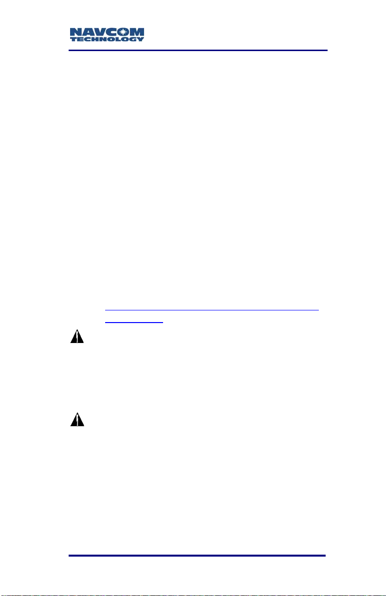
ANTENNA
Refer to Figure 1 for the steps below:
Use one of the two supplied data cables for
1.
communications:
COM1 - LAN
Figure 1: SF-3050 Rear View
COM2 - USB
SF-3050 User Guide – Rev A
POWER
• DB9S cable (P/N 94-310260-3006LF):
Connect the Positronic connector end to
COM2 - USB at the rear of SF-3050. Connect
the DB9S end to the PC.
Or
• USB 2.0 Device cable (P/N 94-310266-
3006LF): Connect the Positronic connector
end to COM2 - USB at the rear of SF-3050.
Plug the USB plug end into the PC.
For this initial configuration, Bluetooth
connectivity is not available. Refer to
Chapter 3/Communication Ports for
details on th
1-19
e ports.
Page 22

SF-3050 User Guide – Rev A
2. Mount the supplied GNSS antenna (P/N 82001020-3001LF) to a mast. Locate the antenna in
an area with a 360° clear view of the sky.
Refer to Chapter 4/Antennae for additional
considerations and restrictions.
3. Connect the supplied GNSS antenna cable
(P/N 94-310261-3012LF) to the GNSS antenna.
Connect the other end of the cable to the TNC
connector, labeled ANT, at the rear of the
SF-3050.
Refer to Table 22 for longer cable lengths.
4. Perform these steps to setup power:
a. Plug the supplied AC power cord (P/N 73-
200002-0001LF) into the supplied Universal
AC/DC Power Adapter (P/N 82-0200073001LF). The adapter operates on either 120
or 240 VAC power.
The purchase of a separate appliance
cable may be necessary if the VAC
plug configuration needed is not the
standard 2-prong American connector.
b. Connect the female Positronic connector end
of the Power Adapter cable into the male
connector, labeled POWER, at the rear of the
SF-3050.
c. Plug the AC power cord into an AC receptacle.
5. Press the front panel On/Off switch to turn on the
SF-3050 (see Figure 31). All front panel LEDs
illuminate fo
power-up. The Power/GNSS Status LED changes
from Red to Green.
1-20
r a period of 3-5 seconds during
Page 23
SF-3050 User Guide – Rev A
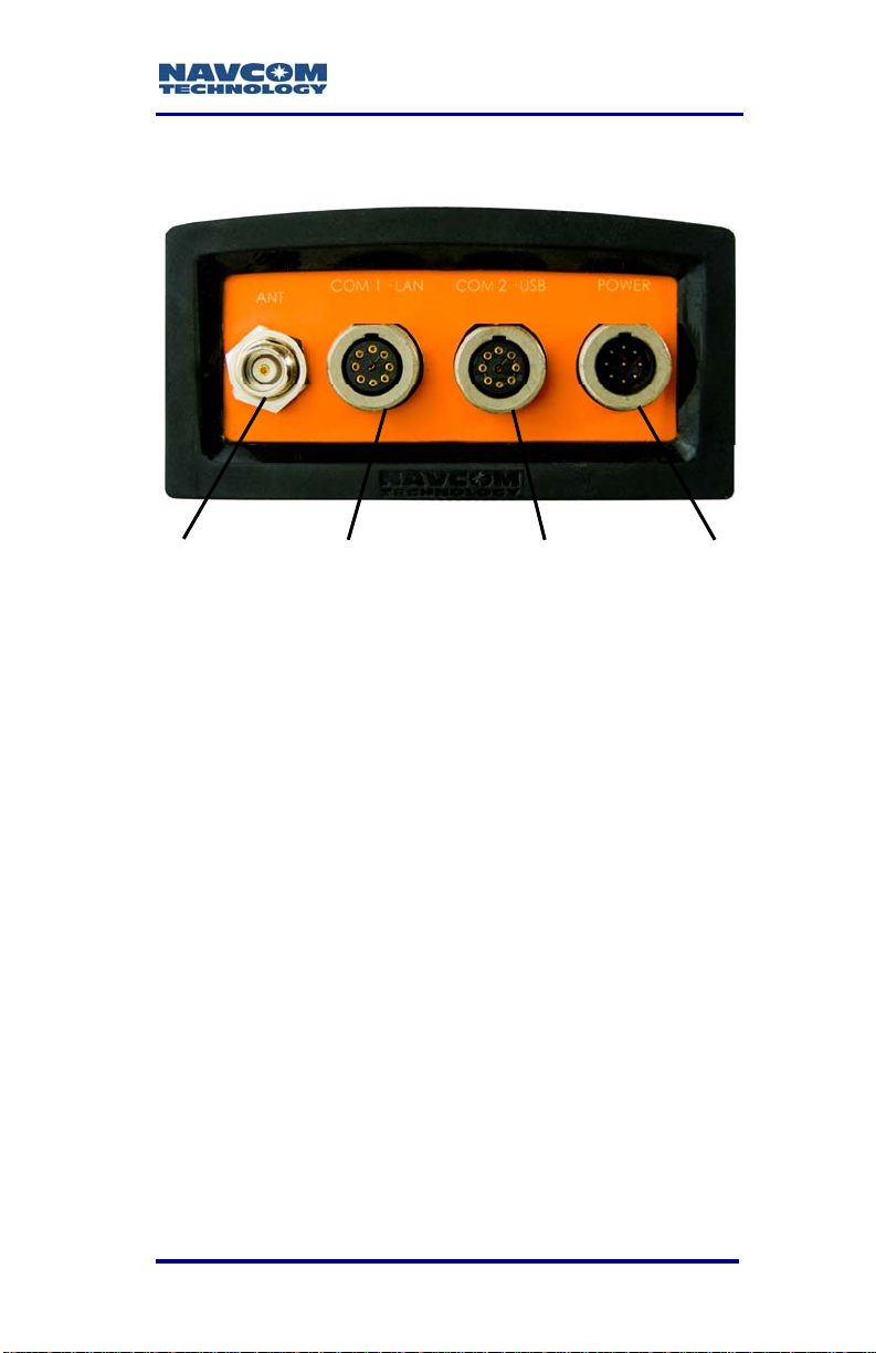
Save Folder/Files to PC
The SF-3050 Product Configuration
USB Flash Drive includes:
• Root Directory: Software Options File and
StarFire License (if purchased)
• NavCom Folder: Includes these sub-folders:
Firmware, Marketing Materials, Utilities,
User Guides, User Profiles. (The contents of
the NavCom folder is subject to change.)
6. Plug the SF-3050 Product Configuration USB
Flash Drive into the PC.
7. Browse to the USB Flash Drive.
8. Save the Software Options File, StarFire License
(if purchased), and NavCom folder to the PC.
Create 2 folders in the NavCom folder for the
Options file and license (see Figure 2).
Figure 2: Folders on PC
Only Software Option and StarFire
License files are sent via email. All other
files are either available on NavCom’s
website or via Customer Support.
1-21
Page 24
SF-3050 User Guide – Rev A
Establish Communications
9. Browse to Navcom\Utilities\StarUtil-3000 on the
PC.
10. Ensure that these files are in the StarUtil-3000
folder: “Starutil-3k_v1_0_x.exe” (program
executable file), “navcomx1c45x3050.inf” (USB
driver), and 96-312007-3001.pdf.
The USB driver must be in the same
folder as StarUtil-3000 for the USB
port to auto-recognize the SF-3050.
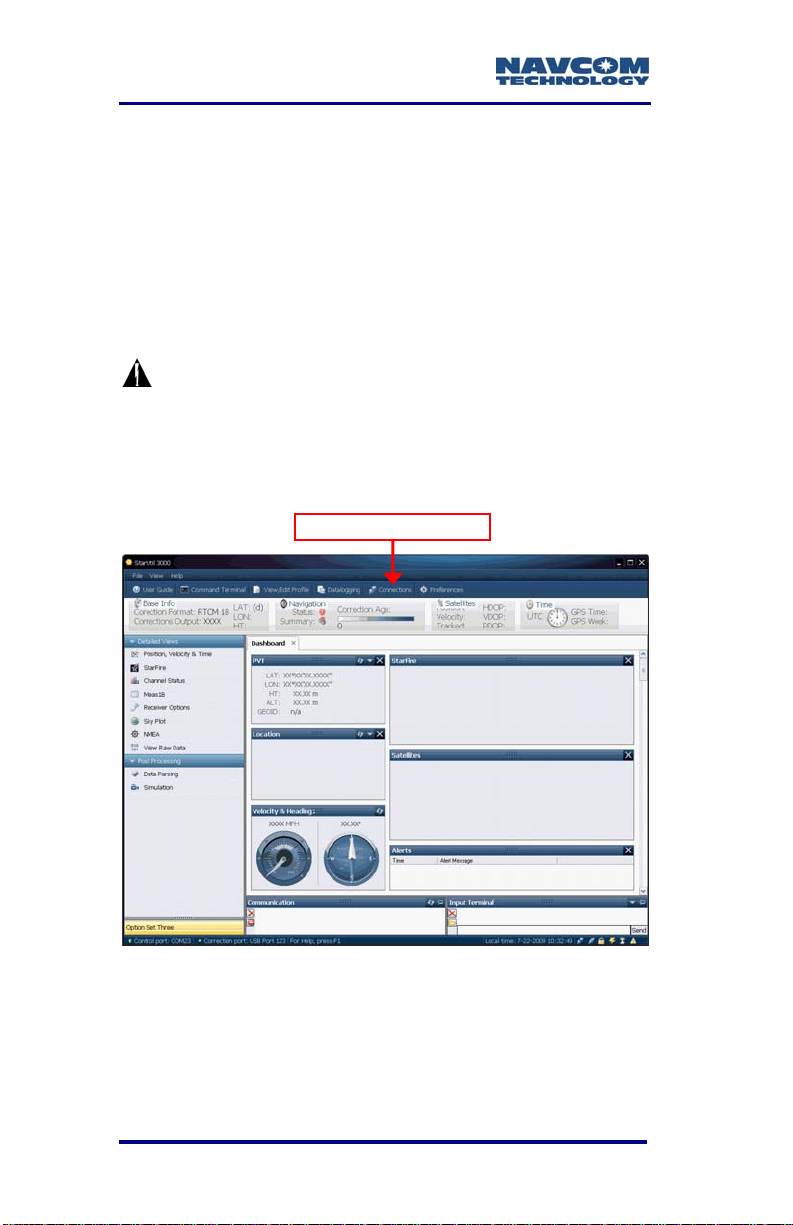
11. Double-click “Starutil-3k_v1_0_x.exe” to open the
program.
Connections Button
Figure 3: StarUtil-3000
12. Click the Connections button to establish
communications between the PC and the
SF-3050 (see Figure 3). The Port Configuration
dialog box opens (see Figure 4).
1-22
Page 25
SF-3050 User Guide – Rev A
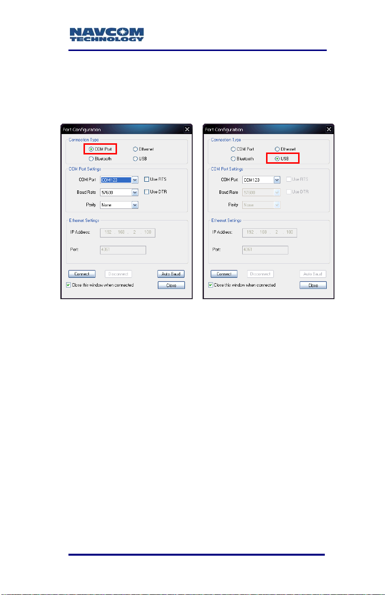
Refer to Figure 4 for the steps below:
13. Depending on the current Connection Type, do
not change the default option, COM Port, or select
USB.
COM Port Settings USB Settings
Figure 4: Port Configuration Dialog Box
14. Set the appropriate options according to the
Connection Type:
• COM Port:
• COM Port: The appropriate PC COM Port
• Baud Rate: 57600 (keep the default)
• Parity: None (keep the default)
Or
• USB Port:
• COM Port: The appropriate virtual PC
COM Port
15. Click the Connect button at the bottom of the
dialog box.
1-23
Page 26
SF-3050 User Guide – Rev A
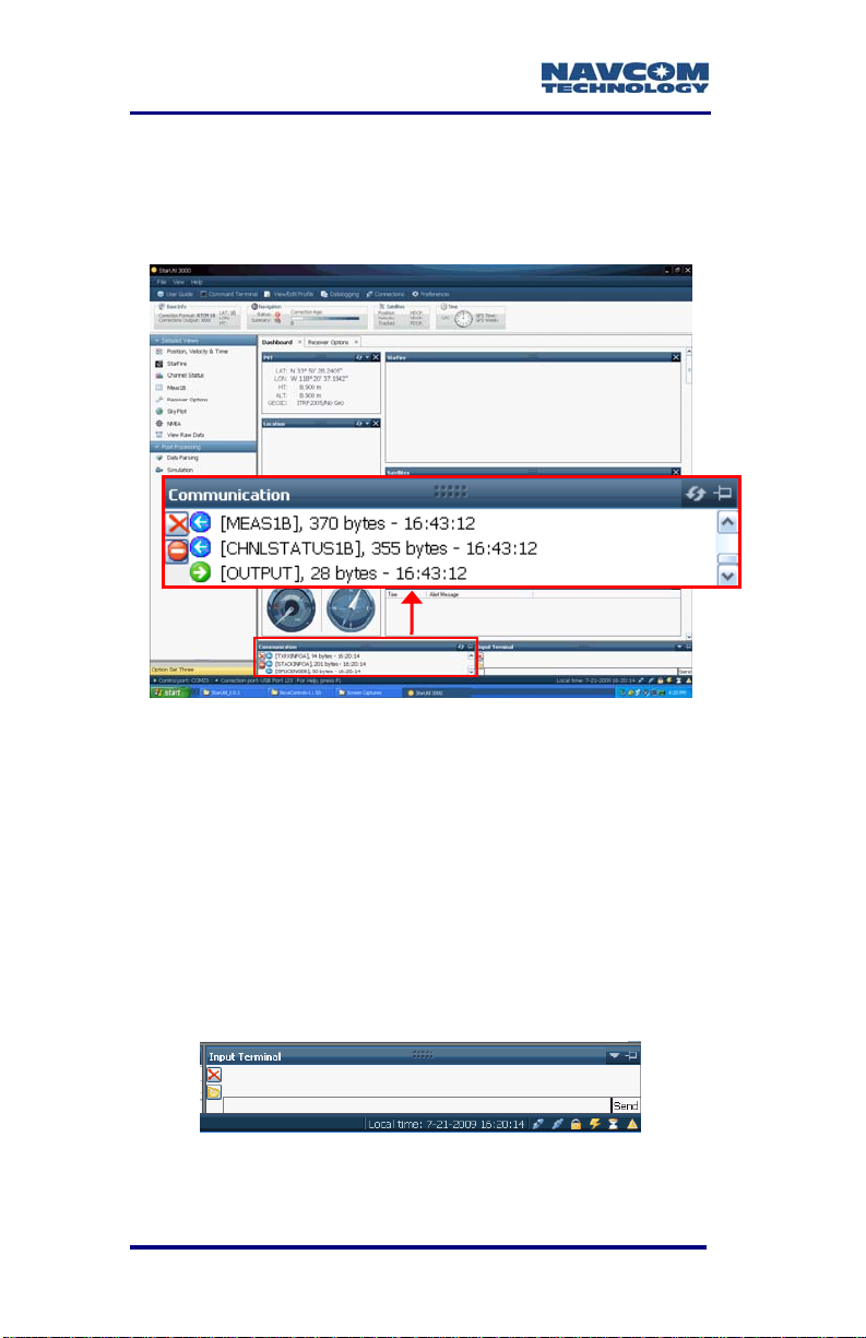
16. Verify that the SF-3050 is connected to the PC.
Messages scrolling in the Communication window
indicate that the connection is established (see
Figure 5).
Figure 5: StarUtil-3000 Communication Window
Determine Current Firmware Versions
In this section, the user determines if the firmware
installed in the SF-3050 is the most current. The
version of the installed firmware is important to
ensure the proper operation of the receiver.
17. Locate the Input Terminal window at the bottom
right of StarUtil-3000 (see Figure 6).
Figure 6: Input Terminal Window
1-24
Page 27
SF-3050 User Guide – Rev A
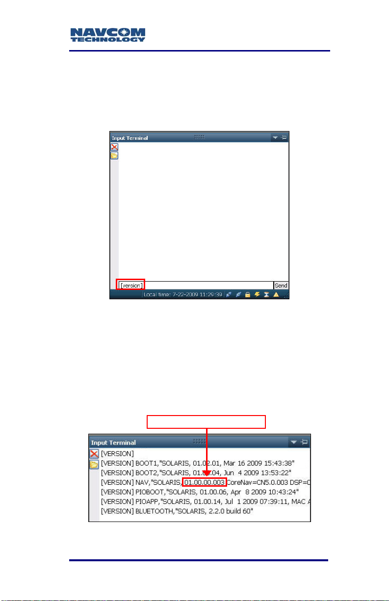
Refer to Figure 7 for the steps below:
18. Enlarge the Input Terminal window.
19. Type [version] in the field at the bottom of the
Input Terminal window.
Figure 7: Version Command
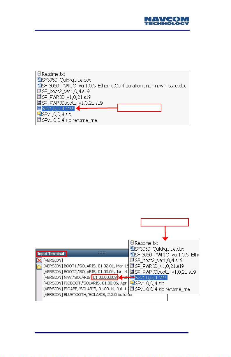
20. Click the Send button. The receiver returns a list
of the currently installed firmware.
The firmware is identified by version
number, for example, the NAV
firmware displayed in Figure 8 is
version 01.00.00.003.
NAV Firmware Version
Figure 8: Example of Installed Firmware
1-25
Page 28
SF-3050 User Guide – Rev A
21. Browse to NavCom\Firmware on the PC. The
Firmware folder contains the most current
firmware (see example files in Figure 9). The
firmware file extension is *.s19.
NAV Firmware
Figure 9: Firmware Folder
22. Compare the current NAV Firmware version in the
Firmware folder with the installed version
displayed in the Input Terminal window (see
Figure 10).
In the example below, the NAV firmware
in the Firmware folder is more current
than the installed firmware. As a result,
the user must update the NAV firmware
in the receiver.
Figure 10: Co
1-26
Firmware Folder
mparing Current & Installed Firmware
Page 29
SF-3050 User Guide – Rev A
23. Perform one of these steps:
• If the NAV firmware installed in the receiver is
the most current version, go to the Upload
Software Op
•
If the NAV firmware installed in the receiver is
not the most current version:
• Check the versions of the other firmware.
• Write down all the firmware that must be
updated.
• Go to the Upload Firmware section below.
tions section below.
Upload Firmware
The required PC Baud rate to upload
firmware via the supplied DB9S cable
(RS-232) on COM2 is 57600 (default). This
requirement does not apply to the supplied
USB 2.0 Device cable.
Typically, if any firmware needs to be
updated, it is NAV and PIOAPP.
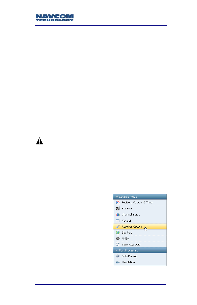
24. Click Receiver Options in
the Detailed Views menu
on the left side of the GUI
(see Figure 11). The
Receiver Options tab
opens.
Figure 11: Receiver Options
1-27
Page 30
SF-3050 User Guide – Rev A
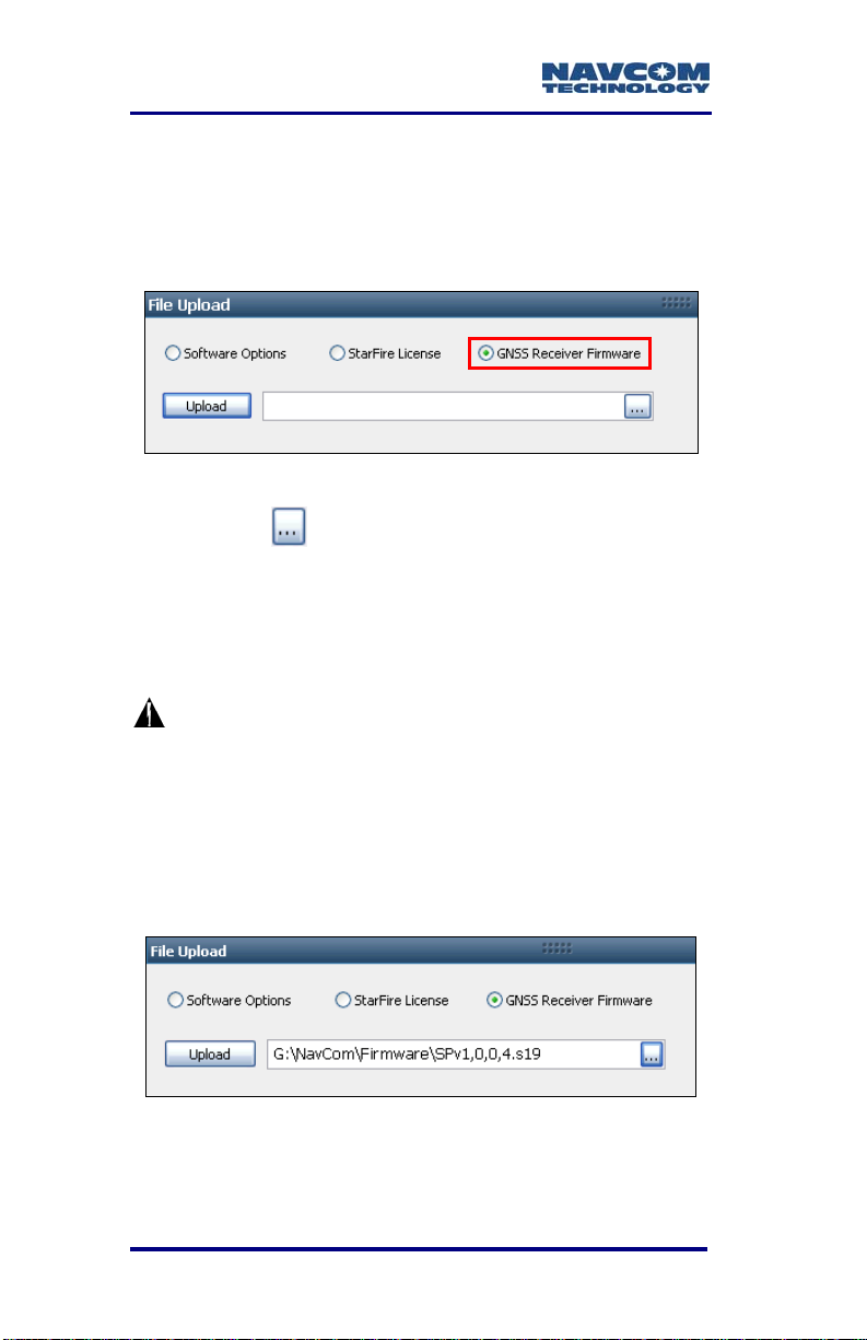
25. Select GNSS Receiver Firmware in the File
Upload window (see Figure 12).
The File Upload window is at the top
right of the Receiver Options tab.
Figure 12: GNSS Receiver Firmware
26. Click the
27. Browse to NavCom\Firmware on the PC.
28. Select the appropriate firmware file. The path to
the file appears in the upload field (see Figure 13
for an example).
button.
Upload Boot files before application
files if both types require updating.
Example Boot File: SP_boot2_ver1,0,4.s19
The format of the NAV firmware file is:
SPv + version number.s19
Example NAV File: SPv1,0,0,4.s19
Figure 13: Firmware Upload
29. Click the Upload button. An upload progress
window opens.
1-28
Page 31

SF-3050 User Guide – Rev A
At the end of upload, a confirmation box
opens (see Figure 14).
Figure 14: Successful Firmware Upload
30. Repeat the last four steps above to upload more
firmware files if necessary.
31. Do not close StarUtil-3000. Continue to the next
section.
Upload Software Options
Software options may be purchased in a bundle
and/or individually. The SF-3050 software bundles
are: SF-3050G, SF-3050S, and SF-3050M. Refer to
Chapter 2/Software Bundles for descriptions of the
software options in ea
Software Options must be uploaded before
the StarFire License (if
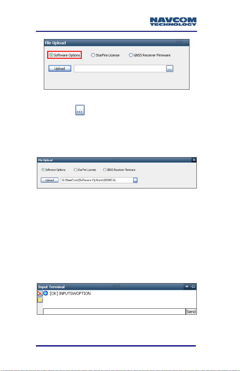
Select Software Options in the File Upload
32.
window (see Figure 15)
1-29
ch bundle.
purchased).
Page 32
SF-3050 User Guide – Rev A
Figure 15: Software Options
33. Click
34.
35. Select the Software Options file. The path to the
36. Click the Upload button. At the end of upload, a
the button.
Browse to NavCom\Software Options on the PC.
The Software Options file extension is *.lic.
file appears in the upload field (see Figure 16).
Figure 16: Software Options Upload
confirmation box opens.
The Input Terminal window also displays the
outcome of the upload (see Figure 17). In the
example bel
Refer to the Sapphire Technical Reference
manual for detailed information on the
INPUTSWOPTION command (see Related
Documents in the fore-matter).
ow, the upload is successful.
Figure 17: Successful Software Options Upload
1-30
Page 33

SF-3050 User Guide – Rev A
Refer to Figure 18 for the step below:
37. Click the Refresh button on the GNSS Receiver
window. This ensures that the loaded Software
Options are displayed in the window.
If any of the purchased Software Options
are not displayed in the GNSS Receiver
window, immediately contact NavCom
Customer Support. Refer to the beginning
of this chapter for contact information.
“StarFire: Option Enabled” indicates
that the StarFire Software Option is
loaded. It does not indicate that a
StarFire License is installed.
Figure 18: GNSS Receiver Window
1-31
Page 34
SF-3050 User Guide – Rev A
38. Do not close StarUtil-3000. Perform one of these
steps:
• If a StarFire License is purchased, go to the
Upload StarFire License section.
•
If a StarFire License is not purchased, go to
the Factory Default User Profile section.
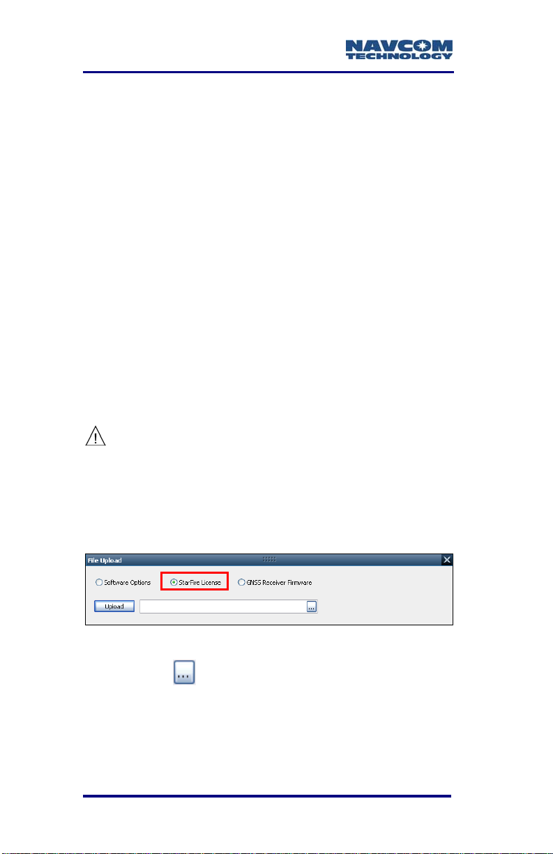
Upload StarFire License
For this initial configuration, the
StarFire license must be installed via
data cable. Subsequent renewals of
the license are typically transmitted to
the receiver via radio broadcast. Refer
to Chapter 5/Over The Air StarFire
Licensing for details.
The receiver must be Tracking GPS
satellites and providing a valid position
solution at the time of the StarFire
license upload to accept the license.
39. Select StarFire License in the File Upload window
(see Figure 19).
Figure 19: StarFire License
40. Click the
41. Browse to NavCom\StarFire License on the PC.
The StarFire License file extension is *.dat.
42. Select the StarFire License file. The path to the
file appears in the upload field (see Figure 20).
1-32
button.
Page 35

SF-3050 User Guide – Rev A
Figure 20: StarFire License Upload
43. Click the Upload button.
The Input Terminal window displays the
outcome of the upload (see Figure 21). In the
example bel
Refer to the Sapphire Technical Reference
manual for detailed information on the
INPUTSFLICENSE command (see Related
Documents in the fore-matter).
Figure 21: Successful StarFire License Upload
ow, the upload is successful.
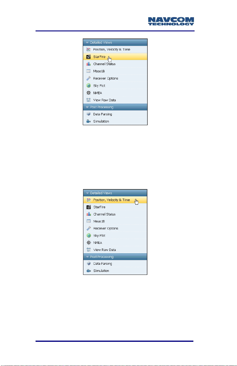
44. Ensure that the purchased StarFire License is
loaded. These tabs provide license information:
• Receiver Options tab: StarFire Licenses and
License Status windows
• StarFire tab: License Info window
To open the StarFire tab, click StarFire in
the Detailed Views menu (see Figure 22).
1-33
Page 36
SF-3050 User Guide – Rev A
Figure 22: StarFire Menu Item
Confirm StarFire Navigation
45. Click Position, Velocity & Time in the Detailed
Views menu to determine if the receiver is
navigating in StarFire mode (see Figure 23). The
PVT tab opens (see Figure 24).
Figure 23: Position, Velocity & Time Menu Item
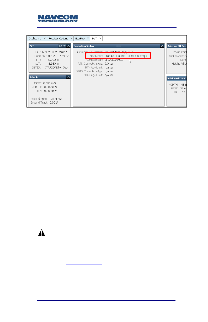
The receiver enters StarFire mode in
approximately 3 minutes after it is first turned
on, then the convergence period starts.
1-34
Page 37
SF-3050 User Guide – Rev A
Figure 24: Nav Mode: StarFire
The Nav Mode above, StarFire Dual:RTG:
3D: Dual freq, indicates that the receiver is
navigating in StarFire dual frequency with a
3D position fix, which is very accurate. RTG is
another term for StarFire (refer to the
Glossary at the end of this guide).
Factory Default User Profile
Further configuration is not necessary for this initial
use of the SF-3050. The receiver is pre-configured
with a factory default user profile that includes
settings for the various port assignments/parameters,
navigation parameters, and output message lists.
If the SF-3050 does not function
properly, refer to these online tools:
• Troubleshooting Guides
• User Manuals
Contact the authorized dealer or NavCom
Customer Support (Refer to the beginning of
this chapter for contact information.)
1-35
Page 38

SF-3050 User Guide – Rev A
Upload User Profile (optional)
If desired, replace the factory default user profile with
a predefined profile, or create a profile. Refer to the
StarUtil-3000 User Guide for instructions .
Predefined user profiles are available in the
Navcom\User Profiles folder saved on the PC.
Refer to Chapter 5/User Profiles for
information on profiles.
1-36
Page 39

SF-3050 User Guide – Rev A
Chapter 2 ..............................Introduction
System Overview
GNSS Sensor System
The SF-3050 Global Navigation
Satellite Systems (GNSS)
sensor delivers superior
accuracy to the precise
positioning community. This
unique receiver is designed
with a robust and long-term
performance upgrade path to meet changing needs
via software upgrades. Increased functionality does
not typically require the costly purchase of additional
hardware.
The SF-3050 software-enabled featu
purchased individually, cover a wide variety of
applications.
The SF-3050 is uniquely suited for real-time
applications in areas such as surveying, machine
control, precise positioning, and construction. The
sensor delivers the required millimeter measurement
precision and fast update rates at low data latency.
Depending on the software bundle, the SF-3050
provides flexibility to be configured as a base station,
or as a rover.
Superior interference suppression (both in-band &
out-band), multipath mitigation, and measurement
accuracy are only a few of the sensor’s technological
advances. The SF-3050 GNSS engine incorporates
several patented innovations advancing the existing
GNSS technology to the next generation. The
receiver provides near optimal GPS P-code recovery,
2-37
res, bundled or
Page 40

SF-3050 User Guide – Rev A
providing a significant signal to noise ratio advantage
over competing technologies, among other benefits.
There are three software bundles: the SF-3050G,
SF-3050S, SF-3050M. Depending upon the bundle,
this receiver provides, but is not limited to:
1
NavCom’s StarFire
Network: A worldwide
Satellite Based Augmentation System (SBAS) for
decimeter level position accuracy (postconvergence period). Refer to Appendix C
for
detailed information.
RTK: This unique receiver is designed to integrate
easily into Real-Time Kinematic (RTK), field data
verification, topographical surveys, and a wide
variety of surveying applications. The system
resolves ambiguities at startup or on satellite
reacquisition typically within 2 seconds. The
SF-3050 delivers centimeter level position
accuracy via external RTK
2
correction formats.
The receiver is capable of NCT RTK/UltraRTK™,
RTCM 2.3 and 3.0 (code and phase), RTCM 3.1,
types 1014-1017 (Network RTK
3
), and
CMR/CMR+ DGPS operating methods. The
operating software is also capable of supporting
an external radio modem.
Signal Reception: The SF-3050 GNSS engine
includes a digital ASIC to handle high speed signal
processing. The sensor provides proven
unparalleled performance in spite of adverse signal
tracking conditions by incorporating the use of GPS
(L1, L2, L2C, L5), GLONASS (G1, G2), Galileo (E1,
E5a), and SBAS (WAAS, EGNOS, MSAS, GAGAN)
signals (standard for most software bundles).
66 Signal Channels: Provides the ability to track
Dependent on the bundle:1Subscription and Software Option
Required;
software version 1.0.
2
Separate Software Option Required. 3Not supported in
2-38
Page 41

SF-3050 User Guide – Rev A
multiple frequencies of satellites in several
constellations simultaneously. This allows for
extended navigation in otherwise adverse
conditions for a single constellation. An additional
channel is dedicated to tracking StarFire signals.
The system includes a GNSS antenna, and
interconnection accessories outlined in Table 12.
Performance Upgrade Path
The SF-3050 is designed with a robust and long-term
performance upgrade path to meet changing needs
via software upgrades. The following tables outline
the standard and optional features of each SF-3050
software bundle.
Table 1: Performance Upgrade Path –
Position & Data Rates
Rate
SF-3050 Bundles
G S M
Position, Velocity, and Time
1, 5*Hz Std Std Std
10Hz Opt Opt Std
25*Hz Opt Opt Std
50, 100Hz Opt Opt Opt
Raw Data
1, 5*Hz Std Std Std
10Hz Opt Opt Std
25*Hz Opt Opt Std
50, 100Hz Opt Opt Opt
*5Hz is the default PVT and Raw Data Rate
for software bundles G and S. 25Hz is the
default PVT and Raw Data Rate for bundle M.
2-39
Page 42

SF-3050 User Guide – Rev A
Table 2: Performance Upgrade Path – Signals
Signals
SF-3050 Bundles
G S M
GPS
L1 Std Std Std
L2 Std Std Std
L2C Std Std Std
L5 Std Std Std
GLONASS
G1 Std Std Std
G2 Std Std Std
Galileo (Hardware Ready)
E1 Std Std Std
E5a Std Std Std
Correction Source
SBAS Std Std Std
StarFire1 Std Std Std
1
The StarFire software option is standard for G,
S, and M software bundles. It does not include
a StarFire license, which must be purchased to
use the StarFire subscription service.
Table 3: Performance Upgrade Path – RTK
RTK
SF-3050 Bundles
G S M
RTK Base Opt Std Opt
2-40
RTK Moving
2
Base
RTK Rover Opt Std Opt
RTK Extend
Network RTK2 Opt Std Opt
2
Not available for version 1.0 software.
Opt Opt Opt
Opt Opt Opt
Page 43

SF-3050 User Guide – Rev A
1
2
Table 4: Performance Upgrade Path – 1PPS/Event
SF-3050 Bundles
G S M
1PPS/Event Opt Opt Std
Accuracy
SBAS
When WAAS, EGNOS, MSAS, or GAGAN
(RTCA/DO-229D compliant) SBAS correction signals
are used, the system provides <30cm 2D position
accuracy.
System accuracy with WAAS, EGNOS, MSAS,
or GAGAN signals is subject to the quality and
update rate of these publicly-operated signals.
Refer to Related Standards/Publicly-Operated
SBAS Signals in the fore-matter for contact
information regarding the organizations that
implement the RTCA/DO-229D standard.
StarFire
The system provides <10cm positio
convergence period
1
) when StarFire correction
signals are used.
n accuracy (post-
RTK
The system provides immediate <1cm position
accuracy when UltraRTK
2
correction signals are used
(baseline, <40km, ±1cm +0.5ppm).
After RTK correction signals are received, the
baseline determines how long it takes to enter
RTK mode. A rover close to the base enters
RTK mode almost immediately. For longer
See Glossary or Web-site;
2-41
Dependent on bundle options
Page 44

SF-3050 User Guide – Rev A
baselines, it may take a minute or two.
Features … Applies to All Software Bundles
Output Data Rate
The SF-3050 GNSS receiver can output proprietary
raw data at programmable rates from <
predetermined rates up to 100Hz
1Hz to
1
and Position
Velocity Time (PVT) data at programmable rates from
<
1Hz to predetermined rates up to 100Hz1 through the
data ports
2
with less than 10ms latency. Accuracies
are maintained as each output is independently
calculated based on an actual GNSS position
measurement, as opposed to an extrapolation/
interpolation between 1Hz measurements.
The throughput capacity of the ports is
limited by the Baud rate and the byte
size and number of messages output.
NCT Binary Proprietary Data
The sensor can output proprietary raw data
containing information including (but not limited to):
Satellite Ephemeris (EPEM1B)
Satellite Almanac (ALM1B)
Raw Pseudorange Measurements (MEAS1B)
Position, Height, & Time (PVT1B)
Velocity & Heading (PVT1B)
Signal to Noise (CHNLSTATUS1B)
Channel Status (CHNLSTATUS1B)
Correction Data (mirror data; RTKSTATUS1B)
1
Dependent on bundle options.
Communications Ports, for details.
2-42
2
Refer to Chapter 3,
Page 45

SF-3050 User Guide – Rev A
Event/Marker (EVENTLATCHA)
Measurement Quality (PVT1B and
PSEUDORANGESTATSB)
These data can be integrated in real-time positioning
applications or post-processed against any number of
software applications designed to handle NCT or
RINEX raw data. The Sapphire Technical Reference
Manual is available on NavCom’s web site, which
describes the attributes of each of the input/output
records (see Related Documents in the fore-matter).
NMEA-0183 Data
The SF-3050 is capable of outputting several
standard NMEA-0183 data strings (see Related
Standards in the fore-matter) and several proprietary
data stings. Each data is headed with $GN, except for
MLA, which is headed with $GL. All header formats
are accepted (i.e., $GP, $GL). Proprietary data
strings are denoted with a $PNCT header.
Standard
ALM – GPS Almanac Data
GBS – GPS Satellite Fault Detection
GGA – GPS Fix Data
GLL – Geographic Position – Lat / Lon
GRS – GPS Range Residuals
GSA – GNSS DOP & Active Satellites
GST – GNSS Pseudorange Error Statistics
GSV – GNSS Satellites In View
MLA – GLONASS Almanac Data
RMC – Recommended Min. Specific GNSS Data
2-43
Page 46

SF-3050 User Guide – Rev A
RRE – Range Residual Errors
(This command is not defined in NMEA 0183
Standard version 3.0).
VTG – Course Over Ground & Ground Speed
ZDA – Time & Date
Proprietary (header $PNCT)
Described in the Sapphire Technical Reference
Manual (see Related Documents in the fore-matter)
GGA – GPS Fix with Field 14
GST – GNSS Pseudorange Error Statistics
MDE – Marginally Detectable Error
SET – Solid Earth Tide
Software Bundles
Software Options may be purchased in a bundle
and/or individually.
The Software Options File contains all the purchased
Software Options, whether purchased in a bundle or
individually. The initial Software Options File must be
uploaded to the receiver to enable the functionality of
the SF-3050. Later purchased software upgrades are
also provided in a Software Options File for upload.
2-44
Page 47

SF-3050G
SF-3050 User Guide – Rev A
The SF-3050G is a multi-constellation,
StarFire-enabled
1
GNSS receiver system for users that
require high-availability, world-wide, decimeter
accuracy. Upgrade paths for higher data rates and other
options make the SF-3050G ideal for many Offshore
Survey and Positioning applications:
Nautical Stationkeeping
Dynamic Positioning
Dredging and Offshore Construction
Deep Water Survey
SF-3050S
Adding Base, Rover, and Network RTK2 to the feature
rich SF-3050G receiver, the SF-3050S is a powerful
engine for use in Land Survey applications where
precision is vital. The small form-factor, light weight
(only 1.1 lbs), and Bluetooth connectivity allow the
receiver to fit nicely into a backpack Land Survey
system with only an external RF cable to the
pole-mounted antenna. In addition, the built-in,
high-speed data ports (USB and Ethernet) enable
high-speed data transfer or remote communication to
the receiver.
The SF-3050S sensor meets the needs of a large
number of applications including, but not limited to:
Topographical Surveys in Rough Terrain
High-Accuracy Data Collection for Post-Processing
Real-time Positioning Applications
1
StarFire Software Option is standard. StarFire
subscription is required.
2
Not supported in version 1.0
2-45
Page 48

SF-3050 User Guide – Rev A
SF-3050M
With 25Hz data rate output, 1PPS, and Event Marker
features standard, the SF-3050M is a hard-working
GNSS receiver targeted towards any application
requiring high-precision data at a high rate. Users
with machine control and aerial survey applications
will appreciate the compact form-factor, powerful
GNSS performance, and critical coordination signals
(1PPS and Event Marker).
The SF-3050M is ideal for vehicle mounting to suit a
wide variety of machine guidance and control
applications in:
Towed Implement Guidance
Construction Machine Control – Blade Control
and Grading
Railway, Ship, and Aircraft Precision Tracking
Port Operations and Container Tracking
Bluetooth
The SF-3050 GNSS receiver is Bluetooth capable in
all software bundle configurations. The Bluetooth
module permits cableless operation between the
sensor and a Bluetooth equipped controller. Wireless
connectivity is provided within a range of 10 meters
(32 feet), and a data rate of 230.4Kbps is supported,
10 Hz maximum. The Bluetooth module contains
Bluetooth certified components, and is FCC and CE
certified. Communications performance is dependent
on the user Bluetooth device used.
Refer to Chapter 3/Bluetooth Communications Setup
for setup instructions via
software utility, StarUtil-3000.
2-46
the supplied NavCom
Page 49

SF-3050 User Guide – Rev A
Antennae
The SF-3050 GNSS sensor must be ordered with the
Rover, Base, or Airborne antenna.
Rover
The Rover integrated
GNSS antenna
(PN: 82-001020-3001LF)
tracks GPS (L1, L2, L2C,
L5), Galileo (E1, E5A),
GLONASS (G1, G2), StarFire (L-Band differential
corrections), and SBAS (WAAS/EGNOS/MSAS/
GAGAN) signals. The compact GNSS antenna has
excellent tracking performance and a stable phase
center. This antenna is listed in the NOAA GNSS
Antenna Calibration tables, as NCT-ANT3001R
robust housing assembly features a standard 5/8”
BSW thread for mounting directly to a surveyor’s
pole, tripod, or mast and is certified to 70,000 feet,
(see Specifications for restrictions).
. The
2-47
Page 50
SF-3050 User Guide – Rev A
Base
The Base integrated GNSS antenna
(PN: 82-001021-3001LF) tracks GPS (L1, L2, L2C,
L5), Galileo (E1, E5A), GLONASS (G1, G2), StarFire
(L-Band differential corrections), and SBAS
(WAAS/EGNOS/MSAS/ GAGAN) signals. The Base
GNSS antenna is designed to reduce multipath error
to provide better RTK corrections to the rover
network. It has excellent tracking performance and a
stable phase center. This antenna is listed in the
NOAA GNSS Antenna Calibration tables, as
NCT-ANT3001B
features a standard 5/8” BSW thread to permanently
install the antenna. It is certified to 70,000 feet (see
Specifications for restrictions).
. The robust housing assembly
2-48
Page 51

SF-3050 User Guide – Rev A
Airborne
The Airborne integrated
antenna (PN: 82-0010223001LF) tracks all GNSS,
WAAS/EGNOS/MSAS/GAGAN and StarFire signals.
The compact GNSS antenna has excellent tracking
performance and a stable phase center for GPS (L1,
L2, L2C, L5), Galileo (E1, E5A), and GLONASS (G1,
G2). This antenna is listed in the NOAA GPS Antenna
Calibration tables, as NCT-ANT3001A. The robust
housing assembly features a flat mounting surface
with four mounting holes and a downward facing TNC
connector. This antenna is also certified to 70,000
feet, and is TSO-C144 certified (see Specifications for
restrictions).
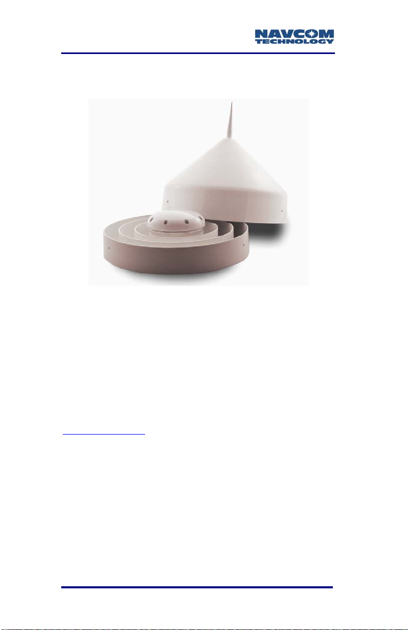
Tall L-band (High Lat L-Band Antenna Kit option)
For challenging operating environments (e.g., high
north and south latitudes), the High Latitude L-Band
Kit (P/N 91-310411-3001LF) enables use of separate
GNSS/SBAS and L-Band antennae (see Figure 49).
The Tall L-b
antenna has excellent tracking performance of
geostationary satellites for latitudes furthest from the
equator. The robust housing assembly features a flat
mounting surface with a 5/8” surveyors mount, two
12’ (3m) coaxial cables with TNC connectors, and a
Combiner (2:1 with 6dB LNA, SF Notch &
Passbands). The SF-3050 uses the GNSS antenna to
receive navigation and SBAS (WAAS/EGNOS/MSAS/
GAGAN) signals, and the Tall L-band antenna to
receive StarFire signals.
2-49
and antenna tracks StarFire signals. This
Page 52

SF-3050 User Guide – Rev A
1
Controller
The SF-3050 GNSS sensor is designed for use with
an external controller solution connected via one of
two Positronic COM ports
This may be accomplished using a PC, Tablet PC or
Personal Digital Assistant (PDA) and a software
program which implements the rich control language
defined for NavCom GNSS products. Refer to the
user’s guide of your controller solution for further
information. NavCom lists several application
software solutions on our website:
http://www.navcomtech.com/Support/ApplicationSoftware.cfm
In addition, NavCom provides a Windows™ based
software utility, called StarUtil-3000, with the receiver.
The StarUtil-3000 User Guide, P/N 96-310029-3001,
is available on-line at
http://www.navcomtech.com/Support/DownloadCenter.cfm?categ
ory=manuals.
1
or Bluetooth.
For initial configuration
2-50
Page 53

SF-3050 User Guide – Rev A
Included Items
Figure 25: SF-3050 Supplied Equipment
Table 5: Supplied Equipment
1 SF-3050 GNSS Sensor (P/N 92-310413-3001LF)
2 GNSS Antenna Cable, 12 ft (P/N 94-310261-3012LF)
Positronic 9-Pin Female Universal AC/DC Power Adapter
3
110-220VAC, 12VDC, 1.50A. (P/N 82-020007-3001LF)
Positronic 9-Pin Male to DB9S (RS-232/RS-422/1PPS)
4
Data Cable, 6 ft. (P/N 94-310260-3006LF)
Positronic 9-Pin Male to USB 2.0 Device Plug, 6 ft
5
(P/N 94-310266-3006LF)
6 Mounting Brackets, 2. (P/N 88-310442-3001LF)
Positronic 9-Pin Female Unterminated Power Cable, 10ft
7
(P/N 94-310262-3010LF) {Not Shown}
SF-3050 Product Configuration USB Flash Drive.
Contains: Software Options file, Firmware file, User
Profiles, User Guides, Brochures, Software Utilities,
8
Technical Papers, and if purchased, a StarFire License
file. (P/N 82-043000-0001) {Not Shown}
Important: Refer to Chapter 1 for steps to enable the
functionality of the SF-3050 via the USB flash drive.
9 Quick Start Guide (P/N 96-310033-3001) {Not Shown}
American 2-Pin AC power Cord, 10 ft
10
(P/N 73-200002-0001LF) {Not Shown}
2-51
Page 54
SF-3050 User Guide – Rev A
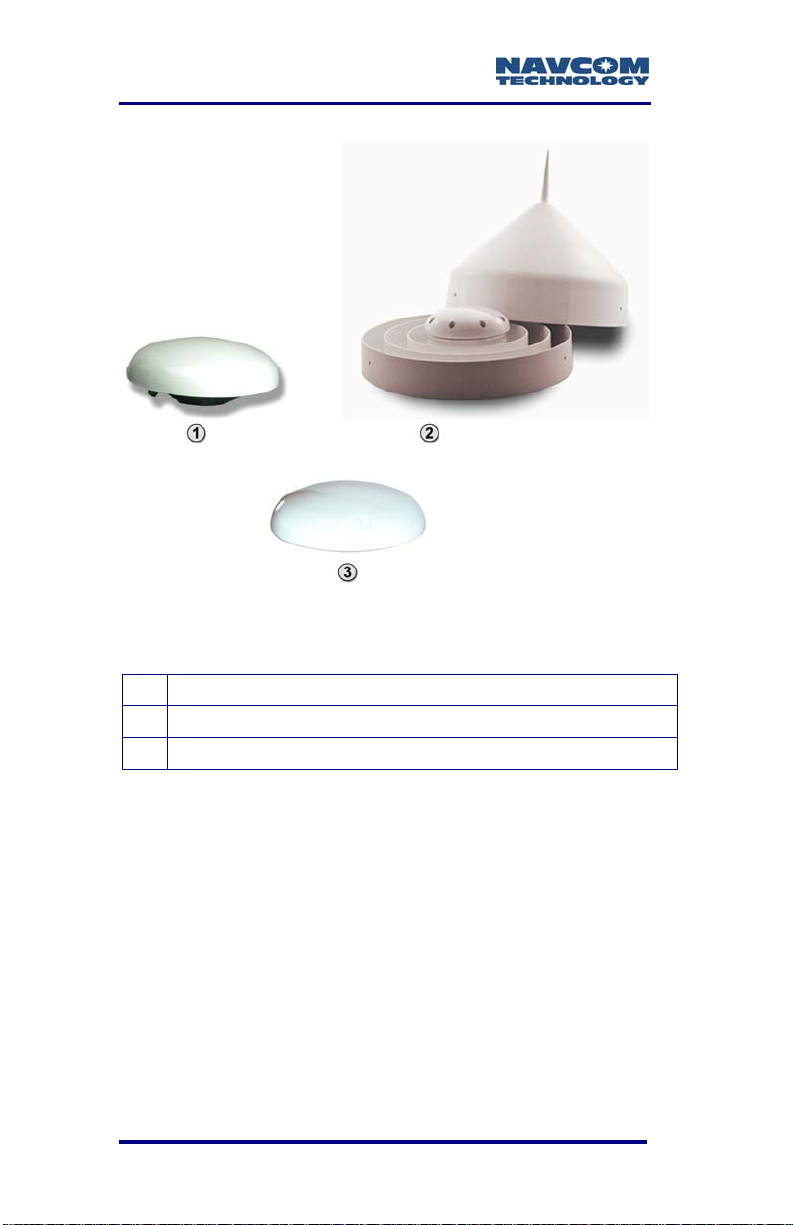
Figure 26: Rover, Base, and Airborne Antennae
Table 6: SF-3050 Antennae
1 Rover GNSS Antenna (P/N 82-001020-3001LF)
2
Base GNSS Antenna (P/N
3
Airborne GNSS Antenna (P/N
82-001021-3001LF)
82-001022-3001LF)
The SF-3050 GNSS sensor must be ordered
with the Rover, Base, or Airborne antenna.
2-52
Page 55

SF-3050 User Guide – Rev A
Applications
The SF-3050 GNSS receiver meets the needs of a
large number of applications. Depending on the
purchased software bundle or individual options, the
applications include, but are not limited to:
Offshore
Nautical Stationkeeping
Dynamic Positioning
Dredging and Offshore Construction
Deep Water Survey
Machine Control and Vehicle Navigation
Towed Implement Guidance
Construction Machine Control – Blade Control
and Grading
Railway, Ship, and Aircraft Precision Tracking
Port Operations and Container Tracking
Land Survey and GIS
Boundary Survey
Topographical Surveys in Rough Terrain
Construction Site Stake-out
High-Accuracy Data Collection for Post-Processing
Hydrographic Survey
Military Applications
Non-Weaponized Military Positioning Applications
Unmanned Systems
Oceanographic Survey and Research
Specialty Applications
Aerial – Photogrammetric Survey
High-Value Asset Location and Tracking
Positioning in Mining Applications
Continuously Operating Reference Stations
Structural Monitoring
Real-time Positioning Applications
OEM Integration
2-53
Page 56

SF-3050 User Guide – Rev A
NavCom lists several application software solutions
on our website:
http://www.navcomtech.com/Support/ApplicationSoft
ware.cfm
Unique Features
The SF-3050 GNSS sensor has many unique features:
Performance Upgrade Path
The SF-3050 is designed with a robust and long-term
performance upgrade path to meet changing needs
via software upgrades. Increased functionality does
not typically require the costly purchase of additional
hardware. The SF-3050 software-enabled features,
bundled or purchased individually, cover a wide
variety of applications.
StarFire
1
The ability to receive NavCom’s unique StarFire
correction service is fully integrated within each unit
(no additional equipment required). A single set of
corrections can be used globally enabling a user to
achieve decimeter level positioning accuracy without
the need to deploy a separate base station, thus
saving time and capital expenditure.
StarFire position outputs are referenced to the
ITRF-05 datum.
Over The Air StarFire Licensing
Over The Air StarFire Licensing is the easiest way
to install a StarFire license. The installation of a
purchased license is accomplished via radio broadcast.
Over The Air StarFire Licensing is especially
convenient for receivers in remote locations in the field.
1
Dependent on Bundle Options: Subscription and Software
Option Required.
2-54
Page 57

SF-3050 User Guide – Rev A
1
NCT RTK/UltraRTK
The RTK/UltraRTK algorithm developed by NavCom
provides fast initialization and the NCT ultra compact
binary data format for RTK/UltraRTK ensures robust
data throughput.
The SF-3050 is capable of outputting or accepting
legacy 0x5B (RTK) or 0x5E (UltraRTK) binary
formats. Refer to the TRM for more details (see
Related Documents in the fore-matter).
Positioning Flexibility
The SF-3050 is capable of using WAAS, EGNOS,
MSAS, GAGAN (RTCA/DO-229D compliant) code
corrections via two internal Satellite Based
Augmentation System (SBAS) channels. The
SF-3050 automatically configures to use the most
suitable correction source available and changes as
the survey dictates (this feature can be overridden).
RTK Extend™
1
RTK Extend
enables continuous real-RTK/RTK level
positioning accuracy during radio communication
outages by utilizing NavCom’s global StarFire
corrections.
Traditionally, when an RTK rover loses
communication with the base station, it is unable to
provide centimeter position updates for more than a
few seconds, resulting in user down-time and
reduced productivity. With RTK Extend, a NavCom
StarFire receiver operating in RTK mode can
transition to RTK Extend mode and maintain
centimeter level positioning during communication
loss for up to 15 minutes. RTK Extend allows more
efficient and uninterrupted work, enabling focused
concentration on the work rather than the tools.
Separate Software Option Required
2-55
Page 58

SF-3050 User Guide – Rev A
RTK Extend is a unique patented technique, not
available on any other manufacturer’s receivers.
Data Sampling
GPS (L1, L2, L2C, L5), GLONASS (G1, G2), Galileo
(E1, E5a), and SBAS (WAAS, EGNOS, MSAS,
GAGAN) raw measurement data is up to 5Hz in the
standard configuration for the SF-3050G and
SF-3050S. An optional upgrade allows 10, 25, 50,
and 100Hz raw measurement data via high speed
ports.
For the SF-3050M, the raw measurement data is up
to 25Hz in the standard configuration, with the
optional upgrade of 50 and 100Hz.
The PVT (Position, Velocity, & Time) data is output at
up to 5Hz in the standard configuration for the
SF-3050G and SF-3050S. An optional upgrade
allows 10, 25, 50, and 100Hz position updates for
highly dynamic applications.
For the SF-3050M, the PVT data is output at up to
25Hz in the standard configuration, with the optional
upgrade of 50 and 100Hz.
GNSS Performance
The SF-3050 utilizes NavCom’s Sapphire GNSS
engine, which incorporates several patented
innovations. Sapphire’s industry leading receiver
sensitivity provides more than 50% signal to noise
ratio advantage over competing technologies. This
results in improved real time positioning, proven
through independent tests, when facing various
multipath environments.
Rugged Design
Units have been tested to conform to MIL-STD-810F
for low pressure, solar radiation, rain, humidity,
2-56
Page 59

SF-3050 User Guide – Rev A
1
salt-fog, sand, and dust. In addition, the unit is IP
certified to the IP67 level.
1
The SF-3050 is also certified
to
comply with the relevant type
approval procedures for marine
equipment of the Marine Equipment
Directive (MED) 96/98/EC. The
“wheel mark” displayed to the right
signifies that the SF-3050 complies
with the MED requirements.
The rugged design of the SF-3050 system
components provides protection against the harsh
environments common to areas such as construction
sites, offshore vessels, and mines.
In some extreme shock and vibration applications,
additional isolation hardware may be required.
Requires use of NavCom’s supplied AC/DC converter.
2-57
Page 60

SF-3050 User Guide – Rev A
This page is left blank intentionally
2-58
Page 61

SF-3050 User Guide – Rev A
Chapter 3 .................................Interfacing
This chapter details the SF-3050 GNSS sensor
connectors, LED display, appropriate sources of
electrical power, and how to interface the
communication ports.
Electrical Power
A rear panel 9-pin Positronic male connector provides
electrical power to the SF-3050. Pin assignments are
given in Table 7; see Figure 30 for pin location on the
connector.
Table 7: Ext
Pin Signal
1 1PPS Out
2 Ignition
3 Event
4 Power Input 9 to 32VDC, 6W typical
5 Power Return
6 Power Input 9 to 32VDC, 6W typical
7 Not Used
8 Not Used
9 Signal GND
ernal Power Cable Pin-Out
Power may be applied to Pins 6 and 4.
Pin 6 is primarily used.
3-59
Page 62

SF-3050 User Guide – Rev A
The SF-3050 is supplied with:
Universal AC/DC, 12V, 1.5A power adapter
(P/N 82-020007-3001LF). See Figure 27.
Positronic 9-
Cable, 10ft (P/N 94-310262-3010LF). See Figure
29.
Figure 27: Universal Power Adapter
Pin Female Unterminated Power
Where MED type approved installations are
required, the SF-3050 must be powered by
the supplied AC/DC power adapter, or an
approved DC to DC power converter.
Contact NavCom Customer Support for
more information:
http://www.navcomtech.com/Contact/Contact
Support.cfm
Replacement AC power cords are
available through small appliance retailers
(Radio Shack, Walmart, Best Buy, etc.).
AC power cords for non-110VAC locales
must be purchased locally.
3-60
Figure 28: AC Power Cord
Page 63

SF-3050 User Guide – Rev A
Figure 29: Unterminated Power Cable
P/N 94-310262-3010LF is the supplied 10ft (3m)
unterminated power cable fitted with a Positronic plug
type (connector: FR11FP9ZZLM0/AA; pin:
FC422N6/AA), used to connect directly to a DC
source. The wiring color code and pin assignments
are provided below.
Table 8: DC Power Cable Pin Assignments
Color Signal Pin No
Blue 1PPS Out 1
Brown Ignition 2
Yellow Event 3
Orange Power Input 4
Black Power Return 5
Red Power Input 6
Green Not Used 7
Violet Not Used 8
Gray GND 9
3-61
Page 64

SF-3050 User Guide – Rev A
Figure 30: Power Cable Pin Assignment
The GNSS sensor is protected from reverse polarity
with an inline diode. It will operate on any DC voltage
between 9 and 32 VDC, 6 watts typical.
Voltages less than approximately
6VDC will turn the unit off. Voltages
from approximately 5VDC to < 7VDC
will create a brown-out. In such a case,
power the unit on as follows:
• Ignition Pin: Provide power ≥ 9 to 32 VDC
• Front Panel On/Off Switch: Press the
On/Off switch to turn the unit off. Then
press and hold the On/Off switch in for
more than 2 seconds to turn the unit on.
To set the receiver to power up as
soon as power is applied to the DC
Input port, use the ignition pin (2) in
conjunction with DC power.
Voltages in excess of 34VDC will
damage the unit. The power supply
must be well conditioned with surge
protection. Vehicular electrical systems
which create voltage spikes in excess
of 34VDC will benefit from providing
power protection during vehicle engine
3-62
Page 65

SF-3050 User Guide – Rev A
power-up. This can be accomplished
through a relay power-on sequence
and/or power conditioning (such as a
DC to DC converter). Do not connect
equipment directly to the vehicles
battery without in-line protection (such
as a DC to DC converter).
Proper Shutdown of SF-3050
To turn off the SF-3050 properly:
Press the On/Off switch on the front panel (see
Figure 31). There may be a delay of
approximate
Or
Switch off power to the ignition pin
ly 2 seconds before the unit turns off.
Do not unplug the positronic end of
the supplied unterminated cable (P/N
94-310262-3010LF) before switching
off power to the ignition pin. The
receiver may not shutdown properly.
3-63
Page 66
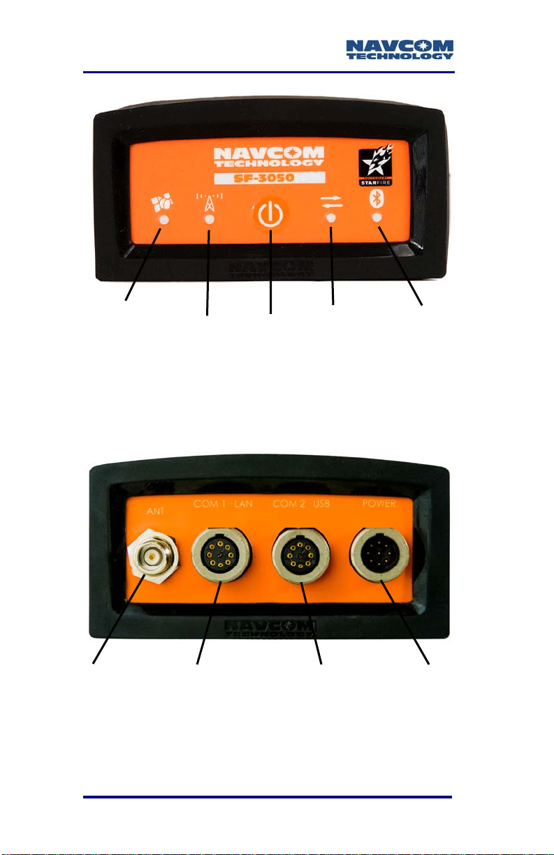
SF-3050 User Guide – Rev A
Power/GNSS
Status
StarFire
Status
Figure 31: SF-3050 Front View
On/Off
Data I/O
Activity
Bluetooth
Connectivity
Refer to the Indicator Panel section below
for descriptions of LED indications.
ANTENNA
3-64
COM1 - LAN
Figure 32: SF-3050 Rear View
COM2 - USB
POWER
Page 67

SF-3050 User Guide – Rev A
Communication Ports
The SF-3050 provides two 9-pin female Positronic
connector communication ports labeled COM1 - LAN
and COM2 - USB located at the rear of the sensor, as
shown in Figure 32 above.
COM1 - LAN conforms to the EIA RS-232 standard
with data rates from 9.6 to 115.2kbps max. It also
conforms to the IEEE 802.3 Ethernet standard with
data rates fr
The COM1 - LAN connector pin-outs are described in
these tables:
RS-232/1PPS: Table 9
Ethernet (LAN): Table 14
om 10 to 100Mbps.
Ethernet (LAN)/RS-232
COM2 - USB conforms to the EIA RS-232/RS-4
standard with data rates from 9.6 to 115.2kbps max.
It is also USB 2.0 compliant with 12Mbps maximum
data rate.
The COM2 - USB connector pin-outs are described in
these tables:
RS-232/RS-422: Table 10
USB 2.0 De
USB 2.0 Ho
USB 2.0 De
The SF-3050 is conf
and desktop computers are configured as DTE
devices. If the supplied cable is not long enough, a
straight-through cable will provide proper connectivity
The SF-3050 provides Bluetooth wireless connectivity
within a range of 10 meters (32 feet). The Bluetooth
module contains Bluetooth-certified components. The
vice: Table 11
st: Table 13
vice/RS-232/RS-422: Table 15
igured as a DCE device. Laptop
Y-Cable: Table 16
22
3-65
Page 68

SF-3050 User Guide – Rev A
data rate for Bluetooth communications is 230.4Kbps.
Refer to the section below, Bluetooth .
There are two supplied
interface data cables:
Positronic 9-Pin Male to DB9S (RS-232/RS-422/
1PPS) (P/N 94-310260-3006LF): constructed as
described in Figure 34 and Figure 35.
Positronic 9-
Pin Male to USB 2.0 Device Plug
(P/N 94-310266-3006LF): constructed as
described in Figure 36.
RS-232/RS-422/1PPS
(P/N 94-310260-3006LF)
USB 2.0 Device
(P/N 94-310266-3006LF)
Figure 33: Supplied Data Cables
The optional interface data cables support USB 2.0
Device and Host, Ethernet, and RS-232 and RS-422
(refer to Table 12).
3-66
Page 69

SF-3050 User Guide – Rev A
Table 9: COM1 Serial Cable Pin-Outs
(P/N 94-310260-3006LF)
Positronic
Pins
Signal Nomenclature
[DCE w/respect to DB9]
DB9S
Pins
1 Not connected 2 Not connected 3 1PPS Out 8
4 RXD RS-232 COM1 3
5 TXD RS-232 COM1 2
6 Not connected 7
7 Not connected 8 Not connected 9 GND 5
Table 10: COM2 Serial
Cable Pin-Outs
(P/N 94-310260-3006LF)
Positronic
Pins
1 Not connected 2 Not connected 3 RXD+ RS-422 8
4 RXD RS-232 COM2/ RXD- RS-422 3
5 TXD RS-232 COM2/ TXD- RS-422 2
6 TXD+ RS-422 7
7 Not connected 8 Not connected 9 GND 5
Signal Nomenclature
[DCE w/respect to DB9]
DB9S
Pins
3-67
Page 70

SF-3050 User Guide – Rev A
PN: 94-310260-3006LF
Positronic
1
2
1
2
3
4
8
9
5
NavCom
7
Receiver
6
COM1
1PPS Out
3
RD RS-232
4
TD RS-232
5
6
7
8
GND
9
Figure 34: COM1 Serial Cable Pin Assignment
PN: 94-310260-3006LF
Positronic
1
2
1
2
3
4
8
9
5
NavCom
7
Receiver
6
COM2
RD RS-232 / RD+ RS-422
3
RD RS-232 / RD- RS-422
4
5
TD RS-232 / TD-RS-422
6
TD RS-232 / TD+ RS-422
7
8
GND
9
Figure 35: COM2 Serial Cable Pin Assignment
DB9S
09-00001-A
DB9S
09-00002-A
1
2
3
4
5
6
7
8
9
1
2
3
4
5
6
7
8
9
3-68
Page 71
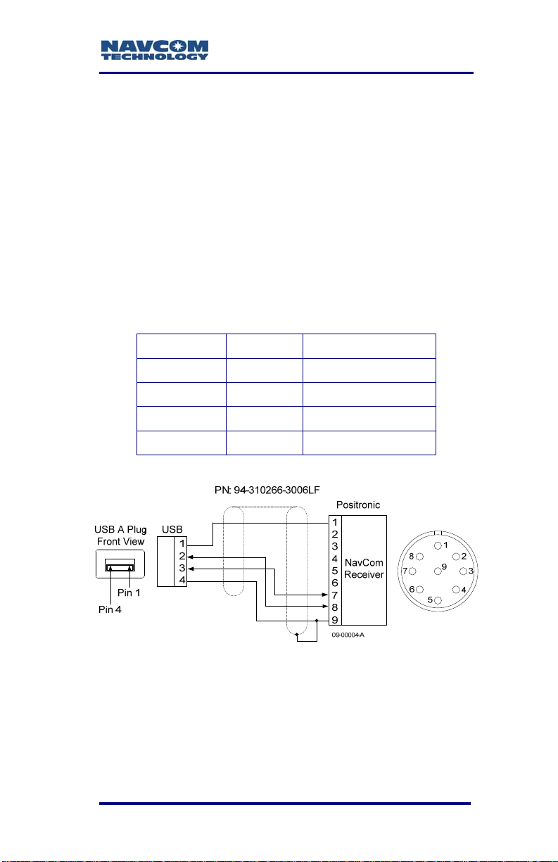
SF-3050 User Guide – Rev A
Supplied USB Device Cable
P/N 94-310266-3006LF is the supplied 6ft (1.83m)
data cable fitted with a Positronic plug type and a
USB A plug type, used to connect as Device directly
to a USB 2.0 connector. The pin assignments are
provided below.
COM2 - USB is the only USB compliant port.
Table 11: USB Device Cable Pin Assignment
(P/N 94-310266-3006LF)
USB Pins Signal Positronic Pins
1 VCC 1
2 Data- 8
3 Data+ 7
4 GND 9
Figure 36: USB Device Cable Pin Assignment
3-69
Page 72
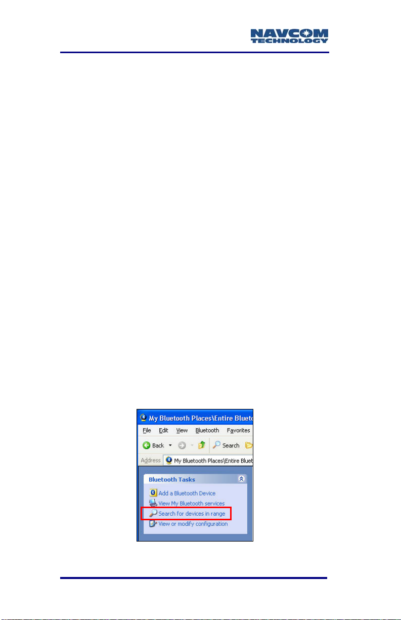
SF-3050 User Guide – Rev A
Bluetooth Communications Setup
This section provides instructions to d
etermine the
Bluetooth Virtual COM port on a PC and connect to
the SF-3050 via Bluetooth.
The SF-3050 Bluetooth Baud rate is fixed at 230400
Baud. It will not connect
at any other speed. The data
rate is 10 Hz maximum. Communications
performance is dependent on the user Bluetooth
device used.
1. Write down the SF-3050 serial number from th
label on the e receiver.
2. Turn on the SF-3050.
3. Plug the Bluetooth don
gle into the proper port on
the PC.
4. Boot up the PC.
5. Right click on the
task bar and select
Bluetooth icon on the Windows
Explore My Bluetooth Places
from the pop-up menu. The Bluetooth window
opens.
Click on Search for devices in range (see
6.
Figure 37
). The window lists all the Bluetooth
devices within range.
Figure 37: Search for Bluetooth Devices in Range
3-70
Page 73

SF-3050 User Guide – Rev A
Figure 38: Bluetooth Devices in Range
is:
7. Do
3-71
The naming convention for the SF-3050
SF-3050ProductTypeSerialNumber, for
example: SF-3050M10278.
The SF-3050 product types are: SF-305
SF-3050S, and SF-3050M.
uble click on the desired SF-3050 in the
Bluetooth device list (see Figure 38
opens with
selected receiver (see
a Bluetooth serial port icon for the
Figure 39).
Figure 39: Bluetooth Serial Port Icon
). A window
0G,
Page 74

SF-3050 User Guide – Rev A
8. Double click on the Bluetooth serial port icon. A
graphic with green arrows indicates a connection
is established between the Bluetooth Virtual COM
port on the PC and the Bluetooth dongle (see
Figure 40).
Figure 40: Bluetooth Virtual COM Port Connection
If the PC asks for a Bluetooth pass code,
click OK. There is no pass code for the
SF-3050 Bluetooth device.
9. Right click on the Bluetooth serial port icon and
select Properties in the pop-up menu. The
Bluetooth Properties window opens.
The window displays the Bluetooth Virtual COM
port assigned to the Bluetooth dongle (see
Figure 41). Remember the COM port number for
use in step 13 below.
Figure 41: Bluetooth Properties
10. Close the Bluetooth Properties window.
3-72
Page 75
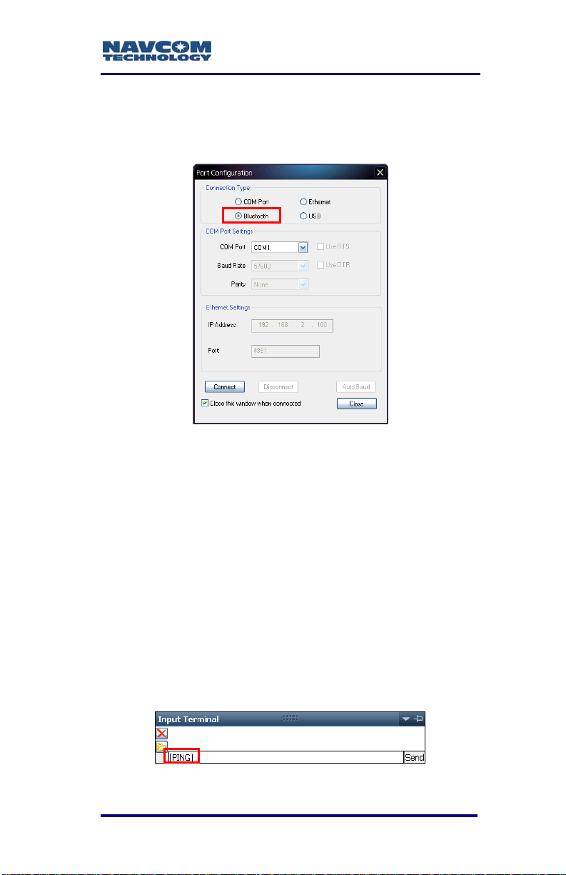
SF-3050 User Guide – Rev A
11. Open StarUtil-3000 on the PC.
12. Click the Connections button in StarUtil-3000. The
Port Configuration dialog box opens.
Figure 42: Bluetooth Port Configuration
Refer to Figure 42 for the steps below:
13. Select Bluet
ooth as the Connection Type.
14. Click the Connect button to connect to the SF-3050.
15. Verify Bluetooth connectivity:
• View the Bluetooth LED on the SF-3050 front
panel. Refer to the Indicator Panel section
below for Bluetooth LED indication
s.
• Type [PING] in the Input Terminal and click
the Send button (see Figure 43). If properly
connected, t
he response is [PING] + current
port number.
Figure 43: Input Terminal PING Command
3-73
Page 76

SF-3050 User Guide – Rev A
Accessories
Optional Data Cables
Figure 44: SF-3050 Optional Data Cables
Table 12: Optional Data Cables
Positronic 9-Pin Male to USB 2.0 Host Receptacle, 6 ft
1
(P/N 94-310271-3006LF)
Positronic 9-Pin Male to Ethernet RJ45 Plug, 6 ft
2
(P/N 94-310265-3006LF)
Y-Cable, Positronic 9-Pin Male to USB 2.0 Device Plug
& DB9S (RS-232/RS-422), 6 ft
3
(P/N 94-310273-3006LF)
Y-Cable, Positronic 9-Pin Male to Ethernet RJ45 Plug &
DB9S (RS-232/1PPS), 6 ft
4
(P/N 94-310272-3006LF)
Refer to Table 5 for the list of supplied
equipment.
3-74
Page 77

SF-3050 User Guide – Rev A
USB Host Cable (Option)
P/N 94-310271-3006LF is an optional 6ft (1.83m)
data cable fitted with a Positronic plug type and a
USB A receptacle type, used to connect as Host
directly to a USB 2.0 connector. The pin assignments
are provided below.
COM2 - USB is the only USB compliant port.
Refer to the section below, Logging to
USB Flash Drive Via USB Host Cable,
for setup an
Table 13: Optional USB Host Cable Pin Assignment
USB Pins Signal Positronic Pins
1 USB PWR 1
2 USB D- 8
3 USB D+ 7
d logging instructions.
4 GND/SHIELD 9
PN: 94-310271-3006LF
USB A
Receptacle
Front View
Pin 4
Pin 1
USB
1
2
3
4
Positronic
1
2
3
4
NavCom
5
Receiver
6
7
8
9
09-00005-A
1
8
7
6
2
9
3
4
5
Figure 45: Optional USB Host Cable Pin Assignment
3-75
Page 78

SF-3050 User Guide – Rev A
Ethernet Cable (Option)
P/N 94-310265-3006LF is an optional 6ft (1.83m)
data cable fitted with a Positronic plug type and a
Ethernet RJ45 plug type, used to connect directly to
an Ethernet connector. The pin assignments are
provided below.
COM1 - LAN is the only Ethernet (LAN)
compliant port.
Refer to the section below, Direct Ethernet
Connection Via Static IP Address, for setup
instruction
Table 14: Optional Ethernet Cable Pin Assignment
Ethernet Pins Signal Positronic Pins
1 TX+ 6
2 TX- 7
3 RX+ 2
s.
6 RX- 1
Figure 46: Optional Ethe
3-76
rnet Cable Pin Assignment
Page 79

SF-3050 User Guide – Rev A
USB Device/RS-232/RS-422 Y-Cable (Option)
P/N 94-310273-3006LF is an optional 6ft (1.83m)
Y-cable fitted with a Positronic plug type on one end.
A USB A plug type and a DB9S female RS-232/
RS-422 connector are fitted on the ends of the
Y-cable. It is used to connect as Device directly to a
USB 2.0 connector or to a DB9S male connector. The
pin assignments are provided below.
COM2 - USB is the only USB compliant port.
Table 15: Optional USB Device/RS-232/RS-422
Y-Cable Pin Assignment
Signal USB Pins Positronic Pins DB9S Pins
USB Power 1 1
2
COM2 RXD+ 3 8
COM2 RXD- 4 3
COM2 TXD- 5 2
COM2 TXD+ 6 7
USB D+ 3 7
USB D- 2 8
GND/Shield 4 9 5
PN: 94-310273-3006LF
PositronicUSB
USB A Plug
Front View
Pin 1
Pin 4
1
2
3
4
1
2
3
4
5
6
7
8
9
1
8
2
9
7
6
5
Positronic Connector
3
Front View
4
Figure 47: Optional USB Device/RS-232/RS-422
Y-Cable Pin Assignment
DB9S
1
2
3
4
5
6
7
8
9
09-00008-A
DB9S
Front View
5
9
4
8
3
7
2
6
1
3-77
Page 80

SF-3050 User Guide – Rev A
Ethernet/RS-232/1PPS Y-Cable (Option)
P/N 94-310272-3006LF is an optional 6ft (1.83m)
Y-cable fitted with a Positronic plug type on one end.
An Ethernet RJ45 plug type and a DB9S female
RS-232 connector are fitted on the ends of the
Y-cable. It is used to connect directly to an Ethernet
connector or to a DB9S male connector. The pin
assignments are provided below.
COM1 - LAN is the only Ethernet (LAN)
compliant port.
Refer to the section below, Direct Ethernet
Connection Via Static IP Address, for setup
instruction
Table 16: Optional Ethernet (LAN)/RS-232/1PPS
s.
Y-Cable Pin Assignment
Signal Ethernet Pins Positronic Pins DB9S Pins
RX- 6 1
RX+ 3 2
3
COM1 RXD 4 3
COM1 TXD 5 2
TX+ 1 6
TX- 2 7
8
GND 9 5
3-78
Page 81
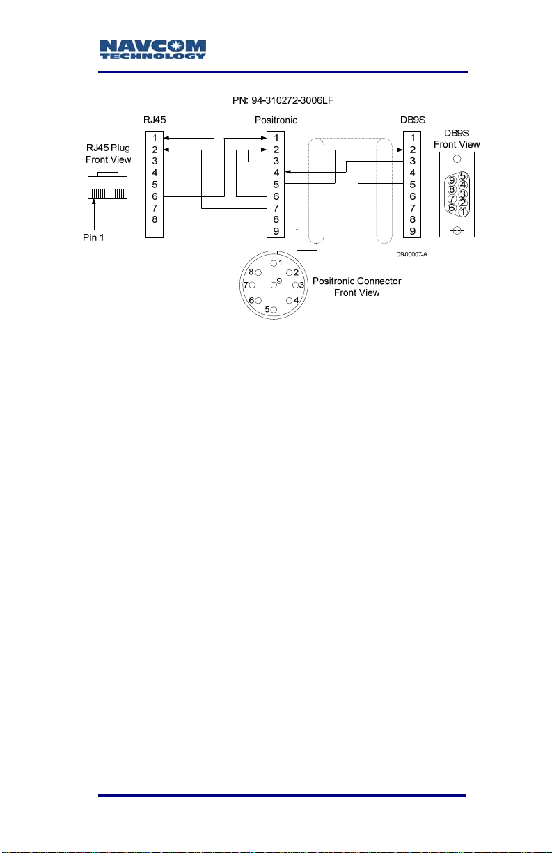
SF-3050 User Guide – Rev A
Figure 48: Optional Ethernet/RS-232/1PPS Y-Cable
Pin Assignment
High Latitude L-Band Antenna Kit (Option)
The High Latitude L-Band Antenna Kit (P/N 91310411-3001LF) is designed for vehicle mounting
with separate antennas for GNSS / SBAS signals
(PN: 82-001020-3001LF) and StarFire. The High
Latitude L-Band Antenna Kit can be added to any
software bundle
antenna systems is to provide better low-elevation
look angles to the StarFire signals in high-latitude
locations.
1
. The purpose of the separate
1
Dependent on the bundle:
Required.
Subscription and Software Option
3-79
Page 82

SF-3050 User Guide – Rev A
Figure 49: High Latitude L-Band Antenna Kit (option)
Table 17: High Latitude L-Band Antenna Kit (option)
High Latitude L-Band Antenna Kit, included:
Tall L-Band Antenna
Combiner, 2:1 with 6dB LNA, SF Notch & Passbands
1
2 GNSS Antenna Cables, 12 ft
(P/N 91-310411-3001LF)
Tall L-Band Antenna
2
(P/N 82-001003-0002LF)
Combiner, 2:1 with 6dB LNA, SF Notch & Passbands
3
(P/N 82-051001-0001LF)
2 GNSS Antenna Cables, 12 ft
4
(P/N 94-310261-3012LF)
3-80
Page 83

SF-3050 User Guide – Rev A
Logging to USB Flash Drive Via USB Host Cable
The [LOGFILE] command used in this
procedure does not work with USB flash
drives that have a write-protected primary
partition. The partition will not mount properly.
The most common examples of this are drives
with U3 software installed. In order to log
using these drives, this partition must be
removed. Reformatting the drive is not
sufficient. According to the U3 web site:
“Most U3 smart drives come with an uninstall
utility that converts the U3 smart drive into a
regular USB flash drive. This utility can be
accessed from the U3 Launchpad. Open the
U3 Launchpad and click on Settings, then
select U3 Launchpad Settings and click on
the Uninstall tab. Some devices have a link to
the Uninstall utility under Help and Support.”
The [LOGFILE] command requires that at
least 10% of the drive is free before it begins
logging. It will also automatically stop logging
when free space drops below 1 MByte.
To view the directory structure and logged
files, the USB drive must be dismounted and
moved to a PC.
To connect as Host directly to a USB flash drive,
requires:
StarUtil-3000: NavCom’s Windows based control
program is included on the supplied SF-3050
Product Configuration USB Flash Drive (P/N 82043000-0001), or provided by email.
Supplied Positronic 9-Pin Male to DB9S Data
Cable (P/N 94-310260-3006LF)
3-81
Page 84
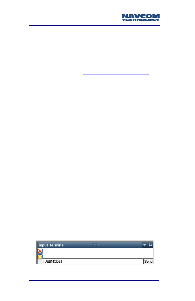
SF-3050 User Guide – Rev A
Positronic 9-Pin Male to USB 2.0 Host Receptacle
Data Cable (P/N 94-310271-3006LF). This cable
is not supplied with the SF-3050.
The USB Host Data Cable is available via a
NavCom authorized representative, or by
contacting the NavCom Sales Department
.
Refer to the section above, USB Host Cable
(Option), for a detailed description of the cable.
Refer to the Sapphire TRM for details on the
commands used in this section. (see Related
Documents in the fore-matter).
Setup
The SF-3050 must be configured in USB Host Mode
to log data to a USB flash drive.
1. Connect the Positronic connector of the supplied
DB9S cable (P/N 94-310260-3006LF) to
COM1 - LAN of the SF-3050. Connect the DB9S
end to the computer.
2. Connect the Positronic connector of the USB Host
cable (P/N 94-310271-3006LF) to COM 2 - USB
of the SF-3050. Plug a USB flash drive into the
USB Host end of the cable.
3. Open StarUtil-3000 on the PC.
4. Locate the Input Terminal window at the bottom
right of StarUtil-3000.
5. Type the command [USBMODE] in the field at the
bottom of the window (see Figure 50).
Figure 50: Input Terminal -- USBMODE
3-82
Page 85

SF-3050 User Guide – Rev A
6. Click the Send button. The receiver returns the
current USB Mode, Device or Host.
7. If the SF-3050 is not in USB Host Mode, type the
command [USBMODE]host.
8. Click the Send button.
9. Type the command [USBMODE] to verify that the
receiver is in USB Host Mode. Click the Send
button. The receiver returns Host as the current
USB Mode.
Logging
To log data t
be logged are first scheduled on a special port, fh1.
“fh” means “file handler”. The command [OUTPUT] is
used to schedule the messages.
1. Open StarUtil-3000, if not already open.
2. Schedule a message to be logged:
a. Type the appropriate [OUTPUT] command
b. Click the Send button.
3. Repeat Step 2 to schedule all necessary
messages.
o the USB flash drive, the messages to
string in the field at the bottom of the Input
Terminal window:
[OUTPUT](message), (timing), (interval), fh1
For example, to output PVT1B at 10Hz, the
command is:
[OUTPUT]PVT1B, ontime, 0.1, fh1
To simplify this process, a profile can
be configured to begin and end data
logging to the USB flash drive.
4. Type the command [LOGFILE]start.
3-83
Page 86
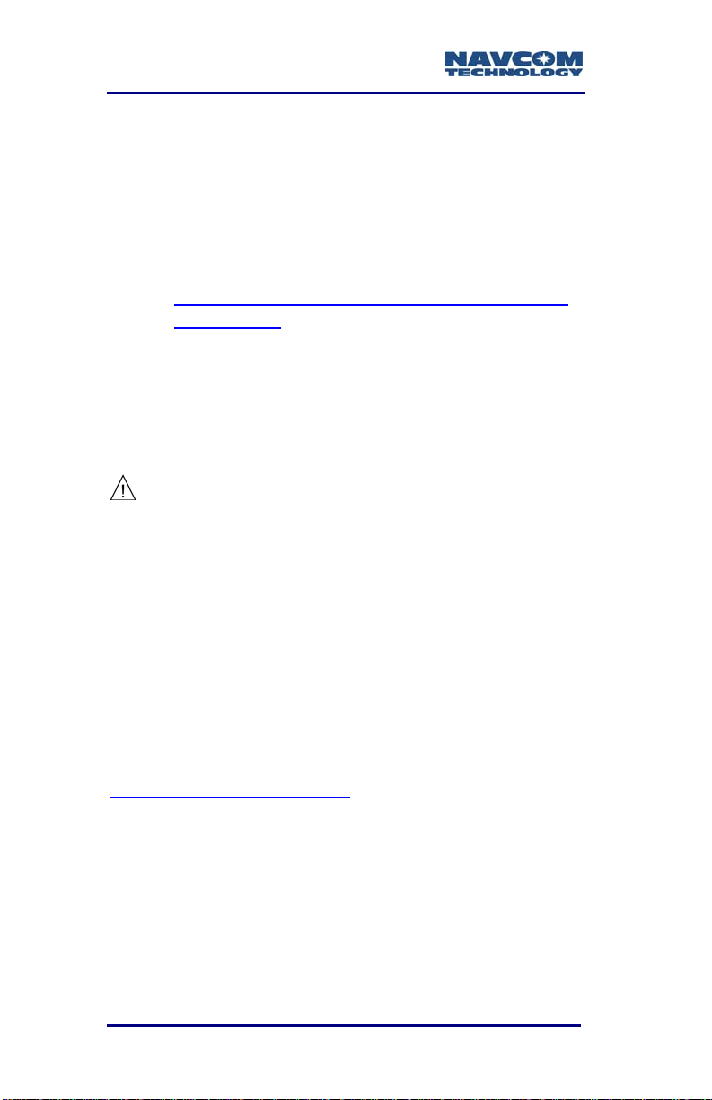
SF-3050 User Guide – Rev A
5. Click the Send button to start logging the
scheduled messages. Messages are logged in
.dat format to the USB flash drive.
If an error message appears, it may be
related to the compatibility of the USB flash
drive. Contact NavCom Customer Support:
http://www.navcomtech.com/Contact/Contact
Support.cfm
The logging commands are: [LOGFILE]start,
[LOGFILE]pause, [LOGFILE]stop,
[LOGFILE]resume, and [LOGFILE] (returns
current logging status). After power cycle, the
file logging is in Stopped status.
To avoid file system corruption on the
USB flash drive, always stop file
logging before removing the drive.
Direct Ethernet Connection Via Static IP Address
There are many possible Ethernet configurations.
This section only provides the basic configuration for
a direct Ethernet connection between the SF-3050
and a PC.
Ethernet cables are not supplied with the SF-3050.
These Ethernet cables are available via a NavCom
authorized representative, or by contacting the
NavCom Sales Department
Positronic 9-Pin Male to Ethernet RJ45 Plug
(P/N 94-310265-3006LF). This cable is used in
the setup below.
Y-Cable, Positronic 9-Pin Male to Ethernet RJ45
Plug & DB9S (RS-232/1PPS) (P/N 94-3102723006LF)
3-84
:
Page 87

SF-3050 User Guide – Rev A
Refer to the sections above, Ethernet Cable
(Option) and Ethernet/RS-232/1PPS Y-Cable
(Option), for detailed descriptions of the cables.
Setup
This setup u
SF-3050:
The PC IP address is set manually in Windows.
1. Connect the Positronic 9-Pin connector of the
Ethernet cable (P/N 94-310265-3006LF) to
COM1 - LAN of the SF-3050. Connect the RJ45
plug end to the computer.
2. In Windows, right click on My Network Places and
select Properties from the pop-up menu. The
Network Connections window opens.
3. Right click on Local Area Connection (or the
equivalent) and click Properties from the pop-up
menu. The Local Area Connection window opens.
4. Click on Internet Protocol (TCP/IP). See Figure 51.
ses the factory default IP address of the
192.168.0.2,255.255.255.0,0.0.0.0
IP Address Network Mask Gateway
Figure 51: Local Area Connection Window
3-85
Page 88
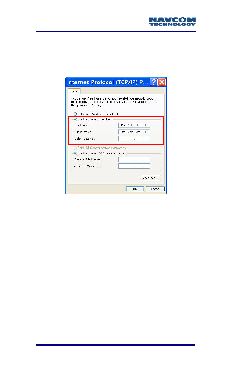
SF-3050 User Guide – Rev A
5. C col
lick the Properties button. The Internet Proto
window opens.
6. Select the option, Use the following IP address
(see Figure 52).
Figure 52: Internet Protocol Window
7. Ente e, enter
The first par
8. Pre Subnet
9. Click the OK button in this window and also in the
10. Continue to the next section for connection
3-86
r
the IP address for the PC. In this cas
192.168.0.100
t of the IP address, 192.168.0,
is the same
PC. The last part of the IP address must
be unique for every device. In this case, it
is 100 for the PC.
ss the Tab button on the keyboard. The
k is aut
mas omatically populated.
Local Area Connection window.
instructions.
for both the SF-3050 and the
Page 89
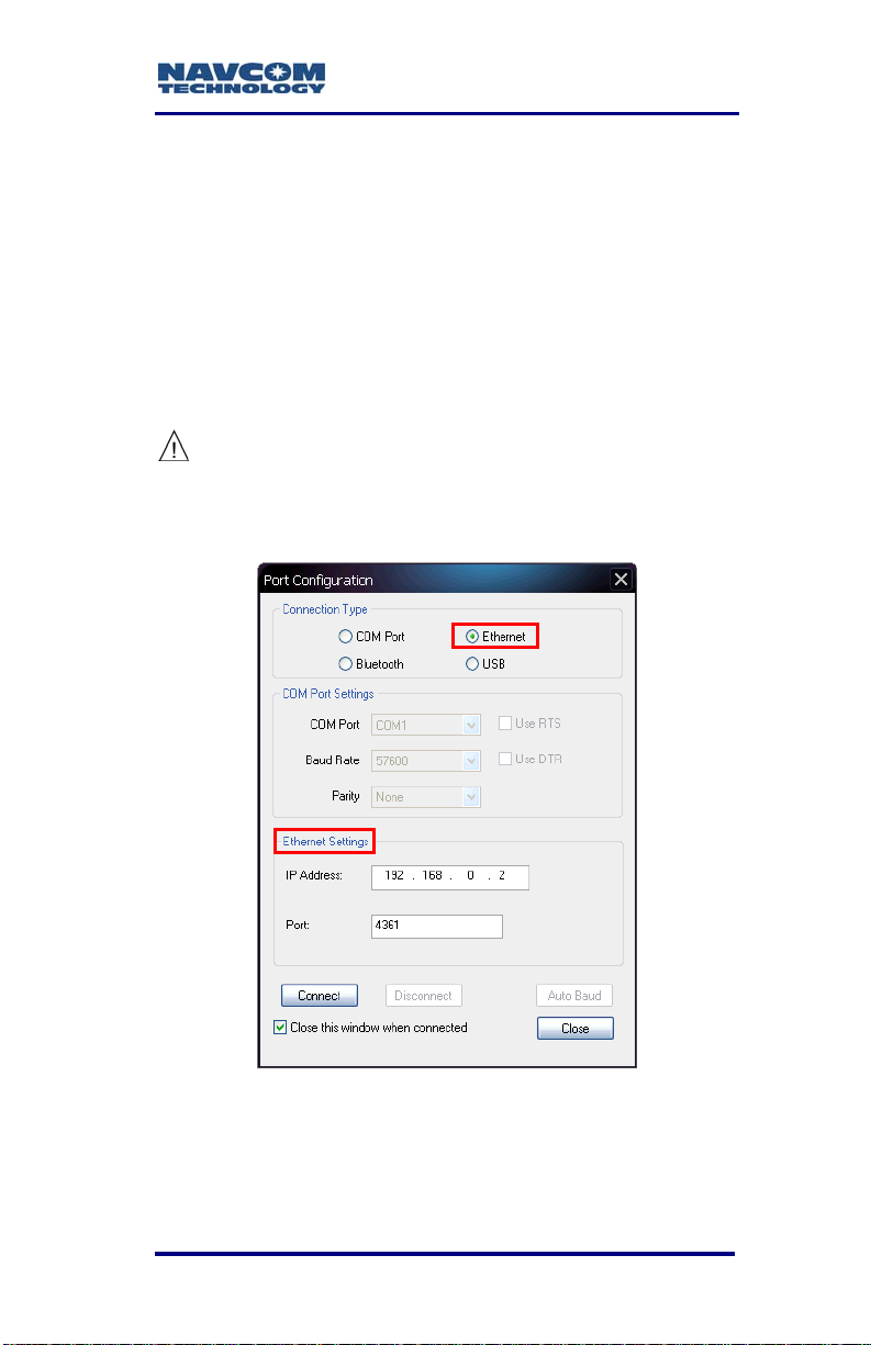
Connect SF-3050 to PC
SF-3050 User Guide – Rev A
Open StarUt1. il-3000 on th
2. Click the Connections blish
communications between the PC
SF-3050. The Port Configuration
opens.
Re
fer to Figure 53 for the steps below:
3. thernet as the
Select E Connection T
e PC.
button to esta
and the
dialog box
ype.
Do not change the default Ethernet
Settings: 192.168.0.2 is the factory
default IP address of the SF-3050.
The default virtual COM port is 4361.
Figure 53: Ethernet Port Configuration
4. Clic
5.
3-87
k the Connect button.
Verify that the SF-3050 is connected to the PC.
Messages scrolling in the C
ommunication window
Page 90

SF-3050 User Guide – Rev A
indicate that the connection is established (see
Figure 5).
If an Ethernet connection is not
established, use StarUtil-3000 to verify
the IP address of the SF-3050. A
serial connection must be used to
determine the receiver’s IP address.
Event
The SFsynchronize
GNSS time t
example, the action of a camera’s shutter create
input pulse to the Event port. The SF-3050M outputs
position and time information relative to each event
received.
The Event is input on Pin 3 of the 9-pin male
Positronic
sensor (refer to Table 7).
Specificatio
Selectable I put Voltan ge, 5V or 12V
Minimu
Rising or Falling edge Synchronizatio
nput,
1 PPS
3050 accepts an event input pulse to
external incidents requiring precise
agging, such as aerial photograph
connector power port on the rear of the
ns:
m pulse width, 100nS
n
Detailed specifications of the Event I
cable wiring,
in Appendix D of this User Guide.
and configuration may b
y. For
s an
e found
A pulse i
rate of once
3-88
s available from the SF-3050 at an output
per second. This pulse can be used for a
Page 91

SF-3050 User Guide – Rev A
variety of Time/ Mark applications where relative
timing is required.
Specifications:
25ns relative a ccuracy
Better than ute accuracy
5V TTL Logic level outp
1 PPS Output Impedance > 50 Ohms
Pulse delay, default 0mS, range 0 – 99
Rising or Falling Edge Synchronization
100ns absol
ut
S, range 10 Pulse width, default 100m – 999mS
9mS
In icator Panel d
Figure 54: SF-3050 Indicator Panel
The indicator panel provides a quick status view of
the GNS e signal
strength, the On/Off (I/O) switch, data I/O and
logging, and Bluetooth connectivity, respectively.
To power the unit on or off, depress the I/O swi
more than 2 seconds. All LEDs illuminate for a pe
of 3-5 seconds during power-up of the GNSS sensor.
S navigation/operating mode, StarFir
tch for
riod
In this chapter, refer to the section, Proper
Shutdown of SF-3050, for details on powering
off the unit.
3-89
Page 92

SF-3050 User Guide – Rev A
GNSS LEDs
Table 18: GNSS LED Indication
Icon
Power/GNSS
StarFire Link LEDs
Table 19: StarFire Link LED Indication
Icon
Indicator Status Description
StarFire
Link
Status Description Indicator
Off
Red
Green
Blinking
Green
Red
Red
Blinking
Green
Blinking
Green
Power off
Power on but not
tracking
Acquiring or tracking
GNSS satellites (no
position fix yet)
Using GNSS
satellites (position
fix)
No StarFire signal
No StarFire License
(or expired)
Acquiring StarFire
signal
Tracking StarFire
signal
3-90
Page 93

Data I/O Active LEDs
Table 20: Data I/O Active LED Indication
SF-3050 User Guide – Rev A
Icon
Indicator tatus Description
Data
S
O
ff
Gr
een
Blinking
Green
The LEDs do not indicat
Data I/O via
Bluetooth Connectivity LEDs
Table 21: Bluetooth Connectivit
Icon
Indicator tus Sta Description
Bluetooth
Ethernet or USB connections.
Off
Blue Blinki ng
Blue
Data I/O inac
Data I/O ac
Loggi
ng data to
i
nternal memory
the status
e of
y LED Indication
Bluetooth off
Bluetooth on,
no connection
uetooth
Bl
connected
tive
tive
3-91
Page 94

SF-3050 User Guide – Rev A
This page is left blank intentionally
3-92
Page 95
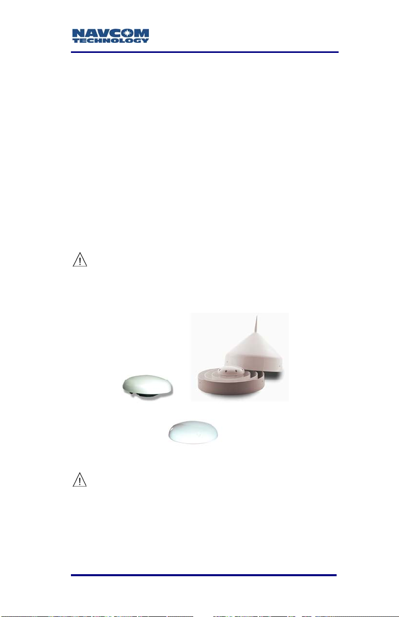
SF-3050 User Guide – Rev A
Chapter 4 .................................Installation
This chapter provides guidance on hardware
in
stallation for optimum performance.
ntennae
A
The 5/8 inch BSW threaded antenna mount has a
d
epth of 16mm (0.63 inch).
It
is possible to remove the 5/8 inch BSW threaded
a
lloy insert to reveal a secondary means of mounting
t
he antenna, a 1-14UNS-2B thread with a depth of
1
6mm (0.63 inch). This is a typical marine industry
m
ount for navigation antennas.
The BSW insert is secured in-place with an
ad the
hesive, and its removal will change
shock and vibration sustainability
characteristics of the antenna mount.
Figure 55: Rover, Base,
Airborne GNSS Antennae
Do not loosen or remove the Phillips screws
on the base of the antenna for mounting
purposes. This will VOID the warranty and
compromise the environmental seal of the
antenna, leading to internal damage.
4-93
Page 96

SF-3050 User Guide – Rev A
Antenna placement is critical to good system
performance. Avoid antenna shading by buildings,
rooftop structures, foliage, hills/mountains, etc.
Locate the antenna where it has a clear view of
the sky, to an elevation angle of 7º if possible.
Obstructions below 15º elevation generally are
not a problem, though this is dependent on
satellite availability for the local region.
Avoid placing the antenna where more than 90º
azimuth of the sky is obstructed. When more than
90º of azimuth is shaded, it is often still possible
for the reciever to navigate, however, poor
satellite geometry (due to satillte shading) will
provide poor positioning results. Even 10º of
shading can have a negative effect on
performance, though this generally is not the
case.
Avoid placing the antenna on or near metal or
other electrically reflective surfaces.
Do not paint the antenna enclosure with a
metallic-based paint.
Avoid placing the antenna near electrical motors
(elevator, air conditioner, compressor, etc.)
Do not place the antenna too close to other active
antennas. The wavelength of L5 is 0.255m and
G1 is 0.187m. The minimum acceptable
separation between antennas is 1m (39 in), which
provides 5.9dB of isolation. For 10 dB of isolation,
separate the GNSS antennas by 2.55m, and for
13dB of isolation (recommended) separate the
antennas by 5.1m.
Active antennas (those with LNA’s or amplifiers)
create an electrical field around the antenna.
These radiated emissions can interfere with other
nearby antennas. Multiple GNSS antennas in
4-94
Page 97

SF-3050 User Guide – Rev A
close proximity to each other can create multipath
and oscillations between the antennas. These add
to position error or the inability to process
satellite signals.
Most antenna’s have better gain w
is high in
to fade as th
unusual to see 10dB difference in antenna gain
(which translates into sig
the entire elevation tracking path.
Map obstructions above the horizon using a
compass and inclinometer. Use satellite predicti
software with a recent satellite almanac to asse
the impact on satellite visibility at that location
(av
elevation. Expect tracking performance
e satellite lowers in elevation. It is
nal strength) throughout
ailable on NavCom’s web site).
hen the satellite
the
not
on
ss
A c the
lear line of sight between the antenna and
loc ck the
al INMARSAT satellite is required to tra
StarFire signal. INMARSAT satellites are geosynchronized 35,768kms above the Equator,
currently at Longitudes 15.5° West, 97.65° West,
142° West, 025° East, 109° East, and
178° East. An inclination and bearing estimation
tool is available on NavCom’s website to aid in
determining potential obstructions to StarFire
signal.
Tall L-band Antenna (High Latitude L-Band Antenna Kit option)
The separate Tall L-band antenna is used in high
latitude applications
vessels. This is an active antenna, meaning it has a
built-in
good is
The be as
the sta orms
with many antenna systems, it is better to locate the
LNA. Therefore, this antenna should have
olation from other near-frequency antennae
st practice is to follow the same precautions
ndard GNSS antenna. On marine platf
and most frequently on marine
.
4-95
Page 98
SF-3050 User Guide – Rev A
standard GNSS antenna closer to the wheelhouse,
but out of the radar or satcom beam path and the
and antenna high on the mast. For best
L-b
performance, do not allow more than 7dB of cable
loss between the antenna, NavCom Combiner (2:1
wit
h 6dB LNA, SF Notch & Passbands) and the
rec n
eiver. Applications without the Tall L-band anten
d
an
operating at high latitudes should mount the
GN ame
SS antenna high on the mast, with the s
considerations for beam path avoidance and cable
loss limitations.
Na
vCom provides a tool on our website to aid in
det na
ermining when the High Latitude L-Band Anten
Kit
is appropriate to use. This tool is for the
SF
-2050R, but also applies to the SF-3050
h Latitude L-Band Antenna Kit due to similariti
Hig e
he primary antenna performance.
in t
http://www.n
ol1/main.cfm
avcomtech.com/Support/Tools/antennato
s
a
GNSS Sensor
Mount the SF-3050 GNSS sensor to a flat surface.
Shock isolators suitable for 0.50kg (1.1 lbs) may be
necessary for environments with high vibration, i.e.
Ea th moving equipment or aircraft installation.
r
e SF-3050 can be installed in a backpack for
Th
bile surveying applications.
mo
not place the sensor in a confined space or where
Do
ay be exposed to excessive heat, moisture, or
it m
midity.
hu
There are no user serviceable parts
inside the SF-3050 GNSS sensor.
Removing the screws that secure the
4-96
Page 99

SF-3050 User Guide – Rev A
front end and rear end plates will void
the equipment warranty.
Figure 56: SF-3050 Base Plate Dimensions Without
Mounting Brackets
4.60" m] m17[1
Figure 57: SF-3050 Base Plate Dimensions With
Mounting Brackets
4-97
Page 100

SF-3050 User Guide – Rev A
Communication Port Connectivity
There is no default control port or data port on the
receiver. COM1 - LAN is the only Ethernet (LAN)
compliant port. COM2 - USB is the only USB
compliant port.
Establish communications via Bluetooth or a data
cable:
Setup Bluetooth communications via either the
supplied StarUtil-3000 utility or a third party
software/utility.
Connect the Positronic 9-Pin connector of the
supplied DB9S cable (P/N 94-310260-3006LF) to
COM1 - LAN (RS-232/1PPS) or COM2 (RS-232/RS-422) of the SF-3050. Connect the
DB9S end to the control device.
Connect the Positronic 9-Pin connector of the
supplied US
3006LF) to COM2 - USB of the SF-3050. Connect
the USB plug end to the control device.
B 2.0 Device cable (P/N 94-310266-
USB
Figure 58 shows a common configuration with
the control d
and an auxiliary device connected to
COM2 - USB for data logging.
evice connected to COM1 - LAN
Some devices may require an additional
adapter. The optional interface data cables
support USB 2.0 Device and Host, Ethernet,
and RS-232 and RS-422 (refer to Table 12).
The receiver is configure
4-98
d as a DCE device
.
 Loading...