

Page 1
S
S
F
F--
3
3
0
0
4
4
0
0
GGNNSSSS RReecceeiivveerr
PPrroodduucctt UUsseerr GGuuiidde
e
NavCom Technology, Inc.
20780 Madrona Avenue
Torrance, California 90503 USA
Tel: +1 310.381.2000
Fax: +1 310.381.2001
sales@navcomtech.com
www.navcomtech.com
PN: 96-310036-3001
Page 2

SF-3040 Product User Guide – Rev. F
This page is left blank intentionally.
Page 3

SF-3040 Product User Guide – Rev. F
Table of Contents
Table of Contents ...................................................... i
List of Figures ......................................................... vi
List of Tables ......................................................... viii
Notices ......................................................................... x
Copyright ..................................................................... x
Trademarks ................................................................. x
FCC Notice ................................................................. xi
User Notice ................................................................. xi
Limited Warranty ....................................................... xii
StarFire™ Licensing .................................................. xii
Software License Agreement .................................... xii
USG FAR ................................................................... xiii
Global Navigation Satellite System ........................... xiii
Revision History .................................................... xiv
Use of This Document ......................................... xvii
Related Documents ...................................................... xvii
SF-3040 Quick Start Guide PN 96-310035-3001 ..... xvii
StarUtil 3000 User Guide PN 96-310008-3001 ........ xvii
Sapphire Technical Reference Manual PN 96-
3120001-3001 ......................................................... xviii
RINEXUtil User Guide PN 96-310021-2101 .......... xviii
NavCom Release Notes .......................................... xviii
Related Standards ....................................................... xviii
ICD-GPS-200 .......................................................... xviii
GLONASS ICD, Version 5.0, 2002 ........................... xix
RTCM-SC-104 .......................................................... xix
NTRIP ....................................................................... xix
CMR, CMR+ ............................................................. xix
RINEX ....................................................................... xix
QZSS ........................................................................ xix
NMEA-0183 ............................................................... xx
Publicly Operated SBAS Signals ............................... xx
Chapter 1 Getting Started ................................ 22
SF-3040 Product Overview ............................................ 24
Product Configuration Files ........................................... 24
Connect the Equipment ................................................. 25
Save Folder/Files to PC ................................................. 28
Establish Communications ............................................ 29
Determine Current Firmware Versions .......................... 33
i
Page 4

SF-3040 Product User Guide – Rev. F
Upload Firmware Files ................................................... 35
Upload Software Options ............................................... 39
Confirm Software Options Are Uploaded to the
Receiver .................................................................... 42
Upload Software Options via the Input Terminal....... 43
Upload the StarFire License .......................................... 43
Confirm StarFire Navigation ...................................... 47
Factory Default User Profile........................................... 48
Upload a User Profile (optional) .................................... 48
Enable or Disable Receiver Tracking and/or Use of
Select Signals and Frequencies .................................... 49
Enable or Disable Receiver Use of Signals and
Frequencies for Navigation ............................................ 50
Chapter 2 Introduction/Features ..................... 52
GNSS Receiver ............................................................. 52
Performance Upgrade Path ........................................... 57
Accuracy ........................................................................ 57
Features ......................................................................... 58
Output Data Rate ...................................................... 58
Sapphire GNSS Binary Proprietary Data .................. 58
Software Options ....................................................... 60
Bluetooth ................................................................... 61
SF-3040 Antenna ........................................................... 61
Controller ....................................................................... 62
Antenna Phase Center Offsets.................................. 63
Applications ................................................................... 64
Land Survey and GIS ................................................ 64
Chapter 3 Interfacing ....................................... 65
Battery Power ................................................................ 65
Electrical Power ............................................................. 66
Proper Shutdown of the SF-3040 .............................. 67
Power Cables ................................................................ 68
Communication Ports .................................................... 71
Supplied USB Device Cable ...................................... 72
Bluetooth Communications Setup ............................. 74
Logging Data to the Removable SD Card ................. 79
Installing the Battery Packs in the SF-3040.................. 84
SF-3040 Indicator Panel LEDs ...................................... 84
Chapter 4 Installation ...................................... 90
GNSS Receiver ............................................................. 90
Batteries ......................................................................... 91
Integrated Antenna ........................................................ 91
ii
Page 5

SF-3040 Product User Guide – Rev. F
Communication Port Connectivity ............................. 93
Auxiliary Communication Module (Internal UHF radio) . 94
Basics of RTK Surveying ............................................... 94
Chapter 5 Configuration .................................. 96
Factory Default Output Messages ................................. 98
Message Descriptions ............................................... 99
Factory Default Settings .......................................... 101
User Profiles ................................................................ 102
Profile NONE ........................................................... 103
Avoiding User Profile Loading Errors ...................... 104
Third-Party Controller Configuration Settings .............. 104
Over the Air StarFire Licensing.................................... 104
Over the Air Broadcast ............................................ 105
Verify License Is Saved ........................................... 105
Setting Up a StarFire Priority Network ......................... 106
RapidRecovery ........................................................ 107
Failed Search .......................................................... 108
StarFire Network List ............................................... 108
Enable or Disable Receiver Tracking and/or Use of
Select Signals and Frequencies .................................. 109
Enable or Disable Receiver Use of Signals and
Frequencies for Navigation .......................................... 109
3rd Party Controller Configuration Settings .............. 110
Chapter 6 Batteries ........................................ 111
Charging the Battery Packs ......................................... 111
Battery Charger LEDs ............................................. 112
Installing the Battery Packs in the SF-3040 ................ 113
Removing the Battery Packs ....................................... 115
Battery Usage and Storage Precautions ..................... 115
Chapter 7 UHF Radio Modem ........................ 119
Licensing Requirements .............................................. 119
Radio Overview............................................................ 119
Technical Specifications .............................................. 121
RF Interface ............................................................. 122
Channel Spacing ..................................................... 123
Data Speed .............................................................. 123
Transmitter .............................................................. 123
Radio Modem Receiver ........................................... 124
Priority RX/TX .......................................................... 125
Forward Error Correction (FEC) and Error Checking125
Installing the Radio Modem ..................................... 125
External Antenna ......................................................... 127
iii
Page 6

SF-3040 Product User Guide – Rev. F
Removing the Radio Modem ....................................... 128
Chapter 8 Safety Instructions ....................... 129
Safety First ................................................................... 129
Transport ..................................................................... 130
Maintenance ................................................................ 130
External Power Source ................................................ 130
Battery Disposal ........................................................... 131
A GNSS Receiver Specifications ...................... 133
Features ....................................................................... 133
Time-to-First-Fix (TTFF) Specifications ....................... 135
Dynamics ..................................................................... 135
Measurement Performance ......................................... 135
Pull-in Times ............................................................ 138
StarFire Rapid Recovery ......................................... 138
User-Programmable Output Rates .......................... 139
Data Latency ........................................................... 139
Bluetooth ................................................................. 139
Connector Assignments .......................................... 139
Input/Output Data Messages................................... 140
Satellite Based Augmentation System Signals ....... 140
Physical and Environmental .................................... 141
Battery Packs .......................................................... 141
B Antenna Specifications ................................. 144
Radiation Pattern ..................................................... 146
C StarFire™ ....................................................... 148
Description............................................................... 148
Infrastructure ........................................................... 149
Reliability ................................................................. 151
StarFire Satellites ........................................................ 153
How to Access the StarFire™ Service ........................ 154
D Networked Transport of RTCM Internet
Protocol (NTRIP) Setup ....................................... 157
Configure the SF-3040 for Wireless Connection ......... 157
Configure the NTRIP Server ................................... 158
Configure the NTRIP Client ..................................... 158
E Software License Agreement ........................ 161
GNSS receiver Embedded Software License Agreement161
Open Source Software License Appendix ................... 169
F RoHS Certification ......................................... 183
Description ................................................................... 183
RoHS 认证 ................................................................... 190
iv
Page 7

SF-3040 Product User Guide – Rev. F
Glossary ............................................................... 199
v
Page 8

SF-3040 Product User Guide – Rev. F
List of Figures
Figure 1: SF-3040, Bottom View ............................. 25
Figure 2: SF-3040 Connectors, Detail..................... 26
Figure 3: SF-3040, Rear View ................................ 27
Figure 4: Indicator Panel ........................................ 28
Figure 5: NavCom Sub-Folders on PC ................... 29
Figure 6: StarUtil 3000, Connections Button ........... 30
Figure 7: Port Configuration .................................... 31
Figure 8: StarUtil 3000 Communication Window ..... 32
Figure 9: Connection at Incorrect Baud Rate .......... 32
Figure 10: Receiver Options Tab ............................ 33
Figure 11: Example of Installed Firmware ............... 34
Figure 12: Firmware Folder .................................... 34
Figure 13: Receiver Options Tab ............................ 36
Figure 14: File Upload – Unified File Loader,
Selected UFL File ........................................... 36
Figure 15: Firmware Folder .................................... 37
Figure 16: Ready to Downline Load File ................. 37
Figure 17: Finished With All Downline Loads .......... 38
Figure 18: Software Options ................................... 39
Figure 19: Software Options File ............................ 39
Figure 20: Software Options File to Upload ............ 40
Figure 21: Successful Software Options Upload ..... 40
Figure 22: Software Options Window ..................... 41
Figure 23: StarFire Licenses Window ..................... 41
Figure 24: Position, Velocity, Time Menu Item ........ 44
Figure 25: Navigation Status Window ..................... 44
Figure 26: Navigation Modes Menu Item ................ 45
Figure 27: StarFire Navigation Mode ON ................ 45
Figure 28: StarFire License .................................... 46
Figure 29: Successful StarFire License Upload ...... 47
Figure 30: StarFire Menu Item ................................ 47
Figure 31: Nav Mode: StarFire ............................... 48
Figure 32: SF-3040 Top View ................................. 62
Figure 33: Indicator Panel On/Off Button ................ 67
Figure 34: Proper External Power Source Setup .... 68
Figure 35: DC Power Cable (Optional) ................... 68
vi
Page 9

SF-3040 Product User Guide – Rev. F
Figure 36: SF-3040 Bottom View ............................ 69
Figure 37: Automotive DC Power Cable with
Cigarette Lighter Adapter (Optional) ................ 70
Figure 38: Universal AC-DC Power Adapter Cable
(Optional) ........................................................ 70
Figure 39: AC Two-Prong Power Cord (optional, with
AC/DC adapter cable) ..................................... 70
Figure 40: COM2 Serial Cable (Standard) ............... 71
Figure 41: USB Device Cable (Supplied) ................ 72
Figure 42: Search for Bluetooth Devices in Range .. 75
Figure 43: Bluetooth Serial Port .............................. 76
Figure 44: Bluetooth Properties ............................... 77
Figure 45: Bluetooth Port Configuration .................. 78
Figure 46: Input Terminal – PING Command and
Response ........................................................ 79
Figure 47: SD Card Chamber Release Button......... 80
Figure 48: SD Card Slot .......................................... 80
Figure 49: SF-3040 Indicator Panel ......................... 84
Figure 50: SF-3040 Indicator Panel, Detail .............. 85
Figure 51: Communication Port Connections .......... 93
Figure 52: Battery Pack Dual-Bay Charger ........... 111
Figure 53: Battery Chamber Release Button ......... 113
Figure 54: SF-3040 Battery Packs Installed in Battery
Chamber ....................................................... 114
Figure 55: Radio Modem ....................................... 120
Figure 56: Radio Modem Chamber Release Button
...................................................................... 126
Figure 57: Radio Modem Installation ..................... 126
Figure 58: Radio Modem Installed in SF-3040 ...... 127
Figure 59: SF-3040 Antenna Polar Plot (Radiation
Pattern) ......................................................... 146
Figure 60: StarFire™ Network ............................... 155
Figure 61: DTE to DCE RS-232 Pin Assignments . 202
vii
Page 10

SF-3040 Product User Guide – Rev. F
List of Tables
Table 1: Supplied Equipment .................................. 22
Table 2: Optional Equipment .................................. 23
Table 3: External Power Cable Pin-Out .................. 66
Table 4: Optional Power Cables ............................. 68
Table 5: Pin Assignments – All Power Cables ........ 68
Table 6: Pin Assignments – USB & COM1 ............. 71
Table 7: Pin Assignments – COM2 ......................... 72
Table 8: Pin Assignments – USB Device Cable Pin
Assignments (Supplied) .................................. 73
Table 9: Bluetooth Connectivity LED Indication ...... 79
Table 10: Data Logging Input Commands .............. 81
Table 11: RTK LED Indicator .................................. 85
Table 12: Power/GNSS LED Indicator .................... 85
Table 13: Data Link LED Indicator .......................... 86
Table 14: StarFire LED Indicator ............................ 86
Table 15: Battery Pack LED Indicator ..................... 87
Table 16: Factory Default NCT Messages/Responses
....................................................................... 98
Table 17: StarFire Satellites v.2.0.15.0 and Later . 108
Table 18: StarFire Satellites v.3.0.12.0 and Later . 109
Table 19: Battery Charger LED Indicators ............ 112
Table 20: UHF Radio Modem Kit, PN 92-210206-
3001LF ......................................................... 120
Table 21: Antenna Selection ................................. 120
Table 22: UHF Radio Modem Specifications ........ 121
Table 23: Transmission Output Power Values, Watts
vs. dBm ........................................................ 123
Table 24: Receiver Sensitivity .............................. 124
Table 25: Battery Maximum Charging Time .......... 142
Table 26: Battery Charger Specifications .............. 142
Table 27: SF-3040 Integrated Antenna ................. 144
Table 28: StarFire Satellites v. 1.0.1.5 and Earlier 153
Table 29: StarFire Satellites v. 2.0.15.0 and Later 153
Table 30: StarFire Satellites v.3.0.12.0 and Later . 153
Table 31: Toxic or Hazardous Substances or
Elements Disclosure by Part Number ........... 183
viii
Page 11

SF-3040 Product User Guide – Rev. F
表32: 按部件号列出的有毒或危险物质或原件...... 191
ix
Page 12

SF-3040 Product User Guide – Rev. F
Notices
SF-3040 GNSS Receiver Product User Guide
PN 96-310036-3001
Revision F
August, 2014
Serial Number:
Date Delivered:
Purchased From:
Copyright
2014 by NavCom Technology, Inc.
All rights reserved. No part of this work or the
computer program(s) described herein may be
reproduced, stored, or transmitted by any means
without the expressed written consent of the copyright
holders. Translation in any language is prohibited
without the expressed written consent of the copyright
holders.
Trademarks
‘find your way’, ‘NavCom Globe’ and ‘NAVCOM
TECHNOLOGY’ logos are trademarks of NavCom
Technology, Inc. StarFire™ is a registered trademark
of Deere & Company. All other product and brand
names are trademarks or registered trademarks of
their respective holders.
x
Page 13

SF-3040 Product User Guide – Rev. F
FCC Notice
This device complies with Part 15 Subpart B Class B
of the FCC Rules. Operation is subject to the
following two conditions:
1. This device may not cause harmful
interference, and
2. This device must accept any interference
received, including interference that may
cause undesired operation.
The GNSS receiver has been tested in accordance
with FCC regulations for electromagnetic
interference. This does not guarantee noninterference with other equipment. Additionally, the
GNSS receiver may be adversely affected by nearby
sources of electromagnetic radiation.
The Global Positioning System (GPS) is under the
control of the United States Air Force. Operation of
the GPS satellites may change at any time without
warning.
User Notice
NavCom Technology, Inc. shall not be responsible for
any inaccuracies, errors, or omissions in information
contained herein, including, but not limited to,
information obtained from third party sources, such as
publications of other companies, the press, or
competitive data organizations.
This publication is made available on an “as is” basis,
and NavCom Technology, Inc. specifically disclaims
all associated warranties, whether express or implied.
In no event will NavCom Technology, Inc. be liable for
direct, indirect, special, incidental, or consequential
damages in connection with the use of or reliance on
the material contained in this publication, even if
advised of the possibility of such damages. NavCom
xi
Page 14

SF-3040 Product User Guide – Rev. F
Technology, Inc. reserves the right to make
improvements or changes to this publication and the
products and services herein described at any time,
without notice or obligation.
Limited Warranty
NavCom warrants that its products will be free from
defects in material and workmanship at the time of
delivery. A full description of the warranty policy is
provided in NavCom’s Standard Terms & Conditions
of Sale For NavCom Products in force at the time of
sale. Please contact your NavCom dealer or NavCom
Sales for a copy of the warranty policy for your
specific product. Please include your model and serial
number, approximate date of purchase, and the
dealer name where the unit was purchased through
so that we may better service this request.
StarFire™ Licensing
The StarFire signal requires a subscription and
software option that must be purchased in order to
access the service. Licenses are non-transferable,
and are subject to the terms of the StarFire Signal
License agreement. For further details on the StarFire
Signal Network, its capabilities, terms and conditions
visit www.navcomtech.com or send an email inquiry
to sales@navcomtech.com
Software License Agreement
By powering on and using this GNSS StarFire™
Receiver, you agree to the terms and conditions of
the NavCom Technology, Inc. GNSS Receiver
Software License and Open Source Software
Licenses. The complete terms and conditions of
these software licenses may be found in the SF-3040
GNSS Receiver Product User Guide, Appendix E.
xii
Page 15

SF-3040 Product User Guide – Rev. F
USG FAR
Technical Data Declaration (Jan 1997)
The Contractor, NavCom Technology, Inc., hereby
declares that, to the best of its knowledge and belief,
the technical data delivered herewith under
Government contract (and subcontracts, if
appropriate) are complete and accurate and comply
with the requirements of the contract concerning such
technical data.
Global Navigation Satellite System
Global Navigation Satellite Systems (i.e., GPS and
GLONASS) are under the control of the respective
Governmental agencies, and the operation of these
satellites may be changed at any time without
warning.
GPS Selective availability (S/A code) was disabled on
02 May 2000 at 04:05 UTC. The United States
government has stated that present GPS users use
the available signals at their own risk.
The U.S. State Department International Traffic in
Arms Regulations (ITAR) regulations limit the
performance of commercial GNSS products. As a
result, access to satellite measurements and
navigation results will be limited from display and
recordable output when predetermined values of
velocity and altitude are exceeded. These threshold
values are far in excess of the normal and expected
operational parameters of the SF-3040 GNSS
receiver.
xiii
Page 16
SF-3040 Product User Guide – Rev. F
Rev. F (Aug 2014)
Chapter 1:Changed Figures 27 and 31
to eliminate StarFire RTG
Chapter 2: Changed StarFire Over IP
to one server/caster.
Added RapidRecovery with
QuickStart feature.
Updated battery pack specs.
Chapter 3: Added part numbers for
cables.
Chapters 4 & 7: Deleted reference to
10W UHF radio.
Appendix A: Corrected StarFire Single
specs, changed RTK Extend
operating time to 15 minutes for
non-NavCom bases.
Added note regarding RTK Extend
maximum performance.
Added specs and note for RTKWL mode
Deleted StarFire Single specs.
Appendix B: Updated phase center
information in Table 27
Appendix C: Added StarFire ITRF-
2008 transition information.
Rev. E (Apr 2013)
Corrected the LEMO 7-Pin USB
Device Cable and LEMO 6-Pin
COM2 Serial Cable part numbers.
Added Appendix E: RoHS certification
(both English and Chinese).
Added Table 31: Toxic or Hazardous
Substances or Elements
Disclosure by Part Number (both
English and Chinese
Chapter 2: Added RapidRecovery
feature
Chapter 4 and 7: Added 1W radio
range considerations
Revision History
xiv
Page 17

SF-3040 Product User Guide – Rev. F
Chapter 5: Added RapidRecovery
feature
Chapter 6: Added two notes regarding
charging batteries 12 hours prior
to use.
Appendix A: Added RapidRecovery
specs
Added note regarding 16GB SD card.
Added note disclaiming UHF range
from baseline lengths
Rev. D (Nov 2012)
Chapter 2: Added definition for DTM in
Standard and Proprietary sections
under NMEA-0183. Added
description of StarFire Over IP.
Added reference to ITRF-2008 datum.
Chapter 5: Added note under NMEA
messages that in software version
3.2.7 and greater, the NMEADTM
will change at the same rate as
the fastest NMEA message
scheduled by user.
Appendix A: Added DTM to the list of
standard NMEA-0183 data strings.
Added note regarding message
scheduling. Added note on
hardware altitude restriction.
Added correction to frequency
operation under Measurement
Performance. Added StarFire
Over IP in features.
Removed all references to Galileo, E1
and E5A.
Updated StarFire Satellite list and
graphic.
Rev. C (Dec 2011)
Chapter 2, SF-3040 Antennae, added
a new link for the antennae
calibration values
Corrected the LEMO 7-Pin USB
Device Cable and LEMO 6-Pin
COM2 Serial Cable part numbers
xv
Page 18
SF-3040 Product User Guide – Rev. F
Chapter 2, 3, and Appendix A: added
Bluetooth operation information
Chapter 7: Added a note regarding
antenna selection
Table 19: updated with new
antenna part numbers
Table 21: Added notes regarding
UHF radio bandwidths and
modulation schemes
Table 24: updated sensitivity
Added a note to External Antenna
Appendix A: updated Measurement
Performance with StarFire GNSS
Rev. B (May 2011)
Chapter 2: corrected Bluetooth
operational range
Chapter 3: added a Note regarding
missing cable pins
Chapter 3: corrected unterminated
power cable rating
Corrected battery operating time from
5hrs to 2.5hrs each (Chapter 3,
Appendix A)
Chapter 8: corrected cleaning agent
statement
Appendix D: added REFSTNPOS
command to Server setup
sequence
Rev. A (Apr 2011)
Initial release
xvi
Page 19

SF-3040 Product User Guide – Rev. F
Use of This Document
This User Guide is intended to be used by someone
familiar with the concepts of GPS and satellite
surveying equipment.
This symbol designates a Note that
provides additional information to make
better use of the product.
This symbol means Reader Be
Careful, and indicates a caution, care,
and/or safety situation. The user might
do something that could result in
equipment damage or loss of data.
Revisions to this User Guide can be obtained in
digital format from
http://www.navcomtech.com/Support/
Related Documents
SF-3040 Quick Start Guide
PN 96-310035-3001
Provides instructions to quickly set up the standard
configuration of the SF-3040
StarUtil 3000 User Guide
PN 96-310008-3001
Describes the operation and use of NavCom’s
Windows-based control program (included on USB
drive)
xvii
Page 20

SF-3040 Product User Guide – Rev. F
Sapphire Technical Reference Manual
PN 96-3120001-3001
Describes the control and output data message
formats utilized by this instrument (for customer
programming purposes; included on USB drive)
RINEXUtil User Guide
PN 96-310021-2101
Describes the conversion program used on NavCom
proprietary output data message formats, to RINEX
ver 2.10 observation and navigation files (for
customer programming purposes; included on USB
drive)
NavCom Release Notes
Describes software updates for NavCom products.
Current and archived Release Notes are available on
the NavCom web site:
http://www.navcomtech.com/Support/DownloadCenter.cfm
?category=releasenotes.
NavCom Customer Support provides software
updates described in the Release Notes. Submit a
request for software updates via the Request Support
web page.
Related Standards
ICD-GPS-200
NAVSTAR GPS Space Segment /Navigation User
Interfaces Standard. ARINC Research Corporation;
2250 E. Imperial Highway; El Segundo, California
90245
xviii
Page 21

SF-3040 Product User Guide – Rev. F
GLONASS ICD, Version 5.0, 2002
Russian Space Agency, Information Analytical Center
Internet: http://www.glonass-ianc.rsa.ru/
RTCM-SC-104
Recommended Standards for Differential GNSS
Service. Radio Technical Commission for Maritime
Services; 1800 N. Kent St, Suite 1060; Arlington,
Virginia 22209
NTRIP
Radio Technical Commission for Maritime Services
(RTCM) Standard 10410.0 (RTCM Paper 2002004/SC104-STD, Version 1.0 for Networked
Transport of RTCM via Internet Protocol (Ntrip)
Radio Technical Commission for Maritime Services
(RTCM) Standard 10410.1 (RTCM Paper 111-2009SC104-STD, Version 2.0 for Networked Transport of
RTCM via Internet Protocol (Ntrip)
CMR, CMR+
Compact Measurement Record; Trimble Navigation
Limited; 935 Stewart Drive; Sunnyvale, CA 94085
RINEX
Receiver Independent Exchange Format;
Astronomical Institute of the University of Berne
QZSS
Quasi Zenith Satellite System. Japan Aerospace
Exploration Agency (JAXA). 7-44-1 Jindaiji Higashimachi, Chofu-shi, Tokyo 182-8522.
xix
Page 22

SF-3040 Product User Guide – Rev. F
NMEA-0183
National Marine Electronics Association Standard for
Interfacing Marine Electronic Devices. NMEA
National Office; 7 Riggs Avenue; Severna Park,
Maryland 21146
Publicly Operated SBAS Signals
RTCA/DO-229D
The Radio Technical Commission for Aeronautics
(RTCA) develops consensus-based
recommendations regarding communications,
navigation, surveillance, and air traffic management
(CNS/ATM) system issues.
RTCA. 1828 L Street, NW, Suite 805, Washington,
DC 20036.RTCA. 1828 L Street, NW, Suite 805,
Washington, DC 20036.
These organizations implement the RTCA/DO-229D
standard set by RTCA:
WAAS (Wide Area Augmentation System)
U.S. Department of Transportation. Federal Aviation
Administration. 800 Independence Ave, SW,
Washington, DC 20591
EGNOS (European Geostationary Navigation Overlay
Service)
European Space Agency. 8, 10 rue Mario-Nikis, F75738 Paris Cedex 15, France
MSAS (MTSAT Satellite-based Augmentation
System)
Japan Civil Aviation Bureau. Ministry of Transport.
Kasumigaseki 2-1-3, Chiyoda-ku, Tokyo 100, Japan
xx
Page 23

SF-3040 Product User Guide – Rev. F
GAGAN (GPS Aided Geo Augmented Navigation)
Indian Space Research Organization. Antariksh
Bhavan, New Bel Road, Bangalore - 560 094, India
xxi
Page 24
SF-3040 Product User Guide – Rev. F
1
SF-3040 Pole-Mount GNSS Receiver
(PN 90-209549-01)
2
LEMO 7-Pin USB Device Cable Coiled 6 ft
(PN 96-212169-01)
3
LEMO 6-Pin COM2 Serial Cable with hardware
handshake 6 ft
(PN 96-212238-01)
4
Two Li-Ion Batteries, 7.4V, 2600 mAh
(PN 98-214946)
5
Battery Charger Kit
(PN 98-214401)
Kit includes:
Dual-Bay Battery Charger
Charger Power Supply w/ cord, 100 – 240 VAC;
50/60 Hz
Car Adapter w/ cord
6
SD Memory Card, 2 GB (PN 25-212850)
7
SF-3040 Software Documentation USB thumb drive
(PN 82-043000-0001)
8
SF-3040 Quick-Start Guide
(PN 96-310035-3001 – hard copy)
Chapter 1 .......................... Getting Started
This chapter provides instructions on enabling the
robust functionality of the SF-3040.
Confirm that all ordered equipment is delivered.
Refer to these tables for detailed lists:
Supplied Equipment: See Table 1.
Optional Equipment: See Table 2.
Table 1: Supplied Equipment
1-22
Page 25
SF-3040 Product User Guide – Rev. F
1
LEMO 2-Pin Universal AC/DC Adapter 100 V240VAC, 12 VDC, 6 ft (North American 2-prong)
(PN 96-212171-01)
2
Power Cord for AC/DC Adapter (North American
2-prong)
3
LEMO 2-Pin DC Power Cable, unterminated, 10 ft
(PN 96-212172-01)
4
LEMO 2-Pin Automotive DC Power Cable, with
cigarette lighter adapter (PN 96-212178-01)
5
LEMO 7-Pin USB Cable, 6 ft (PN 96-212177-01)
6
LEMO 7-Pin COM 1 Serial Cable, 6 ft
(PN 96-212170-01)
7
UHF Radio Module Kit (PN 92-210206-3001LF)
Table 2: Optional Equipment
See Chapter 3 for detailed information on the power
cables.
If any items are missing or damaged,
immediately contact NavCom
Customer Support:
Telephone: +1 (310) 381-2000
Web:
http://www.navcomtech.com/Contact/Contact
Support.cfm
Consult your dealer to determine if the
SF-3040 is already fully configured. If it
is configured, the SF-3040 is ready to
use. To get started, refer only to the
sections below to connect equipment
and operate the receiver.
If the SF-3040 is not dealer-configured,
the receiver is not operational until the
steps in this chapter are performed.
1-23
Page 26

SF-3040 Product User Guide – Rev. F
SF-3040 Product Overview
The robust, lightweight, versatile SF-3040 is
NavCom’s latest addition to its family of
GPS/GLONASS/StarFire Network-capable satellite
receivers.
A basic SF-3040 software package, plus three distinct
software option offerings, provide today’s surveyor
with everything needed:
Basic Software: L1/L2, G1 (G2 or L5), StarFire
Ready
Option: L1/L2, G1 (G2 or L5), StarFire Ready plus
RTK, including Network RTK
Option: L1/L2, G1 (G2 or L5), StarFire Ready plus
RTK, including Network RTK, and RTK Extend
Option: Upgrade from 5Hz to 10Hz
measurements and position
Product Configuration Files
All of the files needed to set up the ordered
configuration of the SF-3040 are included on the
SF-3040 Product Configuration USB Thumb Drive (PN
82-043000-0001). The main product configuration files
are as follows:
Firmware (*.s19): the most current firmware
Software Options (*.opt): The options enable the
functionality of the SF-3040. Software Options
may be purchased individually.
StarFire License (*.lic): The SF-3040 is hardware-
ready for StarFire. The StarFire License and the
StarFire Software Option are required to enable
the StarFire Subscription Service.
1-24
Page 27
SF-3040 Product User Guide – Rev. F
The StarFire License is optional and not
included in the price of the SF-3040.
StarUtil 3000 (Starutil 3000_v1,1,x.exe):
NavCom’s Windows-based control program is
used to upload the product configuration files.
USB Driver (navcomx1c45x3040.inf)
User Profiles (*.npt): The SF-3040 is already
configured with a factory default user profile. If
desired, replace the factory default user profile
with a predefined profile, or create a profile.
Predefined user profiles are available on the USB
flash drive or by email.
Refer to Chapter 5 of the StarUtil 3000 User
Guide for detailed information about user
profiles.
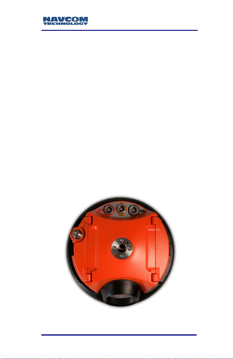
Connect the Equipment
Figure 1: SF-3040, Bottom View
1-25
Page 28
SF-3040 Product User Guide – Rev. F
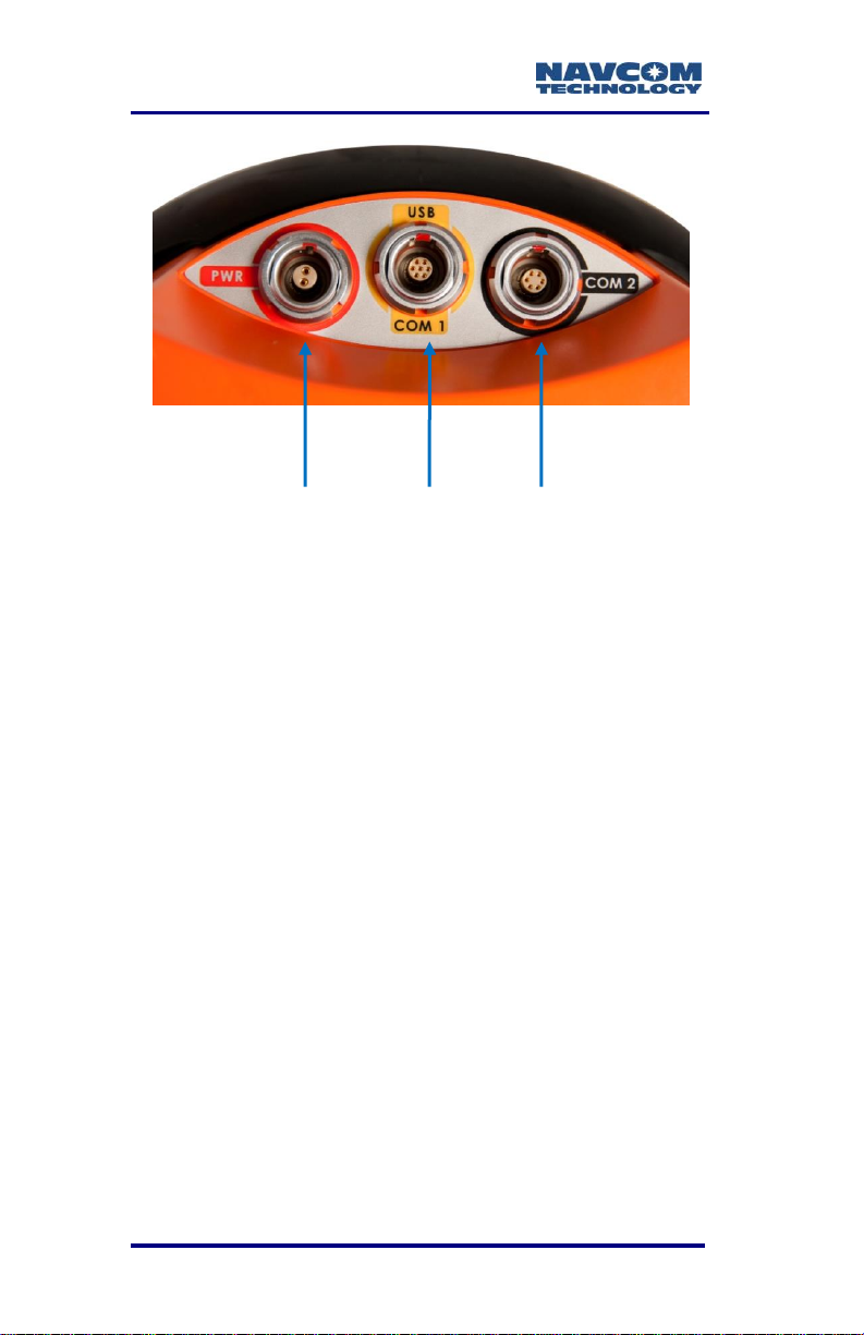
POWER USB/COM1 COM2
Figure 2: SF-3040 Connectors, Detail
Refer to Figure 1 and Figure 2 for the steps below.
1. Connect one of the two supplied communications
cables:
USB Device Cable (PN 96-212169-01): Connect
the 7-pin LEMO connector end to the USB-COM1
port on the bottom of the SF-3040. Plug the USB
end into the PC.
Or
COM2 Serial Cable (PN 96-212238-01): Connect
the 6-pin LEMO connector end to COM2 port on
the bottom of the SF-3040. Connect the DB9S
end to the PC.
1-26
Page 29
SF-3040 Product User Guide – Rev. F
Cable
connectors
Figure 3: SF-3040, Rear View
Refer to Chapter 3 for details on the
communication ports. Refer to the
Bluetooth Communications Setup
section for details on setting up the
Bluetooth connection.
Refer to Appendix A for additional
considerations and restrictions.
Perform these steps to set up power:
1. Fully charge the battery pack for 12-hours after
each use (refer to Charging the Battery Packs in
this guide, if necessary).
2. Insert the batteries into the battery slot (refer to
Figure 54, if necessary).
3. Optional: Plug the optional AC power cord into the
optional Universal AC/DC power adapter.
Connect the male LEMO connector end of the
Power Adapter cable into the female connector
(labeled PWR) on the bottom of the SF-3040. Plug
the AC power cord into an AC receptacle.
1-27
Page 30
SF-3040 Product User Guide – Rev. F
All indicator
panel LEDs
change from
red to green
when power is
ON.
The purchase of a separate appliance cable
may be necessary if the VAC plug
configuration needed is not the standard 2prong American connector.
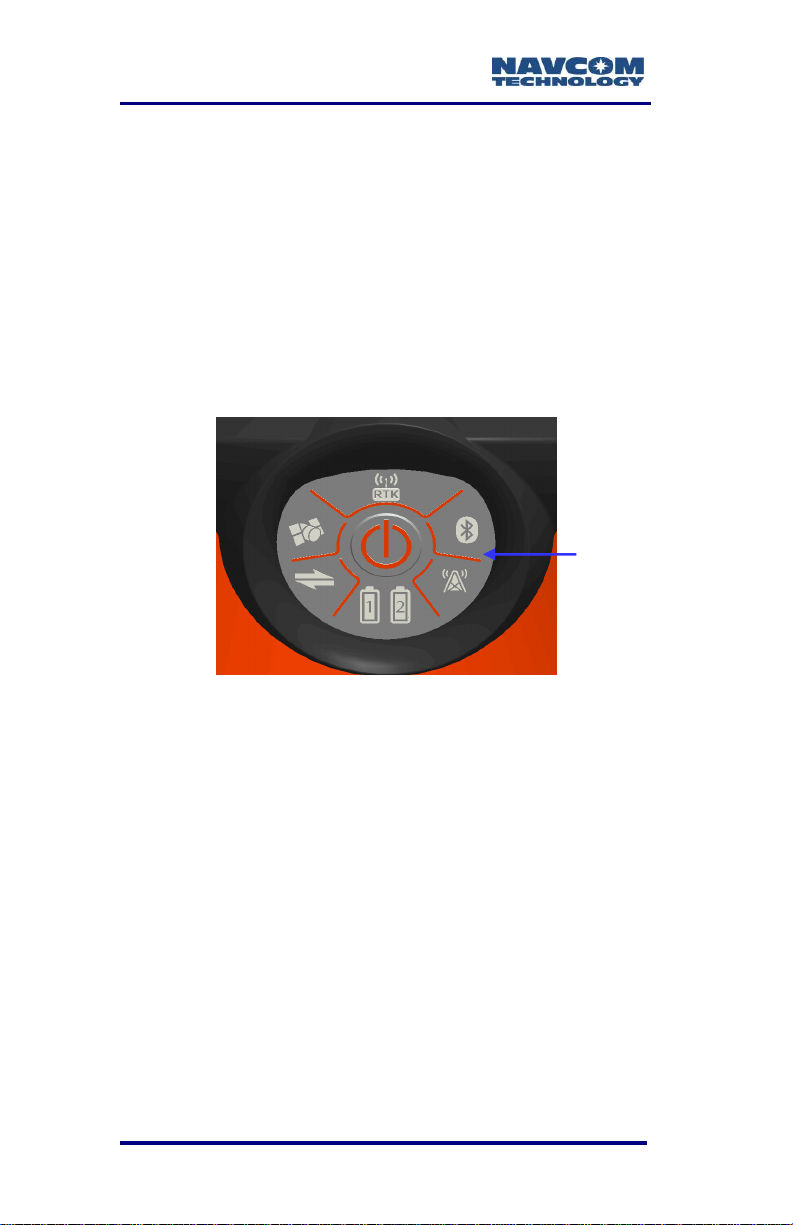
4. Press the front panel On/Off switch to turn on the
SF-3040. All front panel LEDs illuminate for a
period of 3 to 5 seconds during power-up. The
Power/GNSS Status LEDs change from red
(starting up) to green (power is on). (Refer to
Figure 4).
Figure 4: Indicator Panel
Save Folder/Files to PC
The SF-3040 Product Configuration
USB flash drive includes the following:
Root Directory: Software Options File
and StarFire License (if purchased)
NavCom Folder: Includes these sub-
folders: Firmware, Marketing Materials,
Utilities, User Guides, and User Profiles
1. Plug the SF-3040 Product Configuration USB
flash drive into the PC.
1-28
Page 31

SF-3040 Product User Guide – Rev. F
2. Browse to the USB Flash Drive.
3. Save the Software Options File, StarFire License
(if purchased), and NavCom folder to the PC.
4. On the PC, create two folders in the NavCom
folder for the Software Options file and the
StarFire License file (refer to Figure 5) and place
each file in its appropriate folder.
Figure 5: NavCom Sub-Folders on PC
Only Software Options and StarFire
License files are sent via email. All other
files are available either on NavCom’s
website or via Customer Support.
Establish Communications
1. Browse to the folder Navcom\Utilities\StarUtil 3000
on the PC.
2. Ensure that these files are in the StarUtil 3000
folder: “StarUtil3000_v1,1,x.exe” (program
executable file), “navcomx1c45x3040.inf” (USB
driver), 96-312007-3001Revx_Sapphire TRM.pdf,
and 96-310029-3001Revx_StarUtil3000.pdf.
The USB driver must be in the same
folder as StarUtil 3000 for the USB port
to auto-recognize the SF-3040.
1-29
Page 32

SF-3040 Product User Guide – Rev. F
Connections Button
3. Double-click “Starutil3000_v1,1,x.exe” to open the
program.
Figure 6: StarUtil 3000, Connections Button
4. Click the Connections button to establish
communications between the PC and the
SF-3040 (refer to Figure 6). The Port
Configuration dialog box opens.
Refer to Figure 7 for the steps below:
5. Depending on the current connection type, select
COM Port or USB.
1-30
Page 33

SF-3040 Product User Guide – Rev. F
COM Port Settings
USB Settings
Figure 7: Port Configuration
6. Set the appropriate options according to the
Connection Type:
COM Port (on the PC):
Click to connect.
Or
USB (on the PC)
Click to connect.
1-31
COM2 (on the SF-3040)
Baud Rate: 57600 (keep the default)
Parity: None (keep the default)
USB-COM1 (on the SF-3040)
Baud Rate: 57600 (keep the default)
Parity: None (keep the default)
Page 34

SF-3040 Product User Guide – Rev. F
7. Verify that the SF-3040 is connected to the PC:
Scrolling messages in the Communication window
indicate that a valid connection is established at
the required baud rate (refer to Figure 8).
Figure 8: StarUtil 3000 Communication Window
A blue arrow indicates messages
received by the GUI. A green arrow
indicates messages sent by the GUI.
COM Port Connection: Scrolling lines
designated as “DATA” indicate a
connection is established but the baud
rate is not correct (refer to Figure 9).
Reopen the Port Configuration dialog box.
Click or to connect.
Figure 9: Connection at Incorrect Baud Rate
1-32
Page 35

SF-3040 Product User Guide – Rev. F
Firmware Info Window
Determine Current Firmware Versions
The user determines if the most current firmware is
installed in the SF-3040. The version of the installed
firmware is important to ensure the proper operation
of the receiver.
In StarUtil 3000, checking the contents of the
Firmware Info window (refer to Figure 10) on the
Receiver Options tab is the easiest way to determine
if the installed firmware is the most current.
1. Click Receiver Options on the Detailed Views
menu to open the Receiver Options tab (refer to
Figure 10).
2. Click (refresh) on the Firmware Info window to
view the current output data (refer to Figure 11).
1-33
Figure 10: Receiver Options Tab
Page 36

SF-3040 Product User Guide – Rev. F
Click the
Refresh
Button
NAV Firmware Version
Click the
Refresh
Button
NAV Firmware
The firmware is identified by version
number. For example, the NAV
firmware in the example below is
version 02.01.01.006.
Figure 11: Example of Installed Firmware
3. Browse to the NavCom\Firmware folder on the PC
(refer to Figure 5). The Firmware folder is copied
from the SF-3040 Product Configuration USB
Flash Drive. It contains the most current firmware
(refer to Figure 12). The firmware file extension is
*.s19.
Open the Readme.txt file for additional
4. Compare the current NAV Firmware version in the
Firmware folder with the installed version
displayed in the Firmware Info window (refer to
Figure 11 and Figure 12).
1-34
Figure 12: Firmware Folder
information.
Page 37

SF-3040 Product User Guide – Rev. F
5. If the NAV firmware installed in the receiver is not
the most current version:
Check the versions of the other firmware.
Write down all of the firmware that must be
updated.
Go to the section below, Upload Firmware.
Upload Firmware Files
The required PC Baud rate to upload
firmware via the supplied DB9S cable
(RS-232) on COM2 is 57600 (default).
This requirement does not apply to the
supplied USB 2.0 Device cable.
The receiver must be navigating at the
time of the firmware upload. While the
firmware will be accepted and applied
properly, option and license files require
date and timestamp verification.
Typically, if any firmware needs to be updated,
it is NAV and PIOAPP.
1. Click Receiver Options on the Detailed Views
menu to open the Receiver Options tab (refer to
Figure 13).
1-35
Page 38

SF-3040 Product User Guide – Rev. F
Figure 13: Receiver Options Tab
2. Select Unified File Loader on the File Upload
window (refer to Figure 14).
Figure 14: File Upload – Unified File Loader,
Selected UFL File
3. Click .
4. Browse to the NavCom\Firmware folder on the PC
(refer to Figure 15).
1-36
Page 39

SF-3040 Product User Guide – Rev. F
Figure 15: Firmware Folder
5. Select the unified file (UFL) to upload and click
(refer to Figure 14 to view the selected
UFL file).
6. The files to be uploaded are displayed on the
Ready to Downline Load File dialog box with their
corresponding check boxes selected (refer to
Figure 16). Select and deselect files as
necessary.
Figure 16: Ready to Downline Load File
7. Click .
1-37
Page 40

SF-3040 Product User Guide – Rev. F
8. Once the firmware files have been uploaded, the
Finished with All Downline Loads dialog box
showing all the files that were uploaded is
displayed (refer to Figure 17).
Figure 17: Finished With All Downline Loads
9. Click .
10. Check the Firmware Info window (refer to Figure
11) to view the current versions of all uploaded
firmware.
1-38
Page 41

SF-3040 Product User Guide – Rev. F
Upload Software Options
Software options may be purchased individually.
Software Options must be uploaded
before uploading the StarFire License, if
purchased.
The receiver must be navigating at the
time of the software options upload.
1. Select Software Options on the File Upload
window (refer to Figure 18).
Figure 18: Software Options
2. Click .
3. Browse to the Software Options file on the PC.
The Software Options file extension is *.opt (refer
to Figure 19 for an example .opt file).
Figure 19: Software Options File
4. Select the Software Options file. The path to the
file appears in the upload field (refer to Figure 20).
1-39
Page 42

SF-3040 Product User Guide – Rev. F
Figure 20: Software Options File to Upload
5. Click . At the end of the upload, a
confirmation box is displayed. Click OK on the
confirmation box.
The Input Terminal window also displays the
outcome of the upload (refer to Figure 21). In
the example below, the upload is successful.
Refer to the Sapphire Technical Reference
Manual for detailed information on the
INPUTSWOPTION command (see Related
Documents in the fore-matter).
Figure 21: Successful Software Options Upload
6. Click (refresh) on the Software Options
window (refer to Figure 22), and check to ensure
that all uploaded software options are displayed.
1-40
Page 43

SF-3040 Product User Guide – Rev. F
Click the
Refresh
button
Figure 22: Software Options Window
“StarFire: Enabled” indicates that the
StarFire Software Option is loaded. It
does not indicate that a StarFire
License is installed. The StarFire
license information is displayed in the
“StarFire Licenses” window of the
Receiver Options tab (refer to Figure
23).
Figure 23: StarFire Licenses Window
1-41
Page 44

SF-3040 Product User Guide – Rev. F
7. Do not close StarUtil 3000. Perform one of these
steps:
If a StarFire License is purchased, go to the
Upload the StarFire License section.
If a StarFire License is not purchased, go to
the Factory Default User Profile section.
Confirm Software Options Are Uploaded to the
Receiver
The SF-3040 returns the entire list of
loaded software options. However,
StarUtil 3000 may not display the entire
list in the Software Options window.
Follow the below steps to confirm that all
software options successfully uploaded
to the receiver:
1. Type the command [INPUTSWOPTION] on the
Input Terminal window.
2. Click Send.
3. Highlight and copy the entire output.
4. Open any text editor (e.g., Microsoft Notepad) and
paste the output there to verify that all software
options have been uploaded to the receiver.
If the above method fails to upload any of
the purchased software options, refer to
the next section.
1-42
Page 45

SF-3040 Product User Guide – Rev. F
Upload Software Options via the Input Terminal
Perform steps 1 through 5 under Upload Software
Options
Open the software option file in any text editing
program (e.g., Microsoft Notepad).
1. Locate the option code at the bottom of the file
(e.g., 74C91E91 789FA173 8E70296A
3259B2E6).
2. Highlight and copy the option code.
3. Enter the command [INPUTSWOPTION] on the
Input Terminal window and then paste the option
code: 74C91E91 789FA173 8E70296A
3259B2E6.
4. Click Send on the Input Terminal window. If the
software options loaded successfully, the Input
Terminal window displays a confirmation
message (refer to Figure 21).
Upload the StarFire License
For the initial configuration, the StarFire
license must be installed via data cable.
Subsequent renewals of the license are
typically transmitted to the receiver via
radio broadcast. Refer to Chapter 5 for
details.
The receiver must be Tracking GPS
satellites and providing a valid position
solution at the time of the StarFire
license upload to accept the license.
1. To confirm a valid position solution on the PVT
tab/Navigation Status window, click Position,
1-43
Page 46

SF-3040 Product User Guide – Rev. F
Velocity, Time (refer to Figure 24) on the Detailed
Views menu to open the PVT tab (refer to Figure
25 ).
Figure 24: Position, Velocity, Time Menu Item
Click (refresh) on the Navigation Status
window to ensure that the current position
solution is displayed (refer to Figure 25).
Figure 25: Navigation Status Window
1-44
Page 47

SF-3040 Product User Guide – Rev. F
Figure 26: Navigation Modes Menu Item
2. Click Navigation Modes on the Receiver Setup
menu to open the Set Navigation Modes dialog
box (refer to Figure 27).
Figure 27: StarFire Navigation Mode ON
Refer to Figure 27 for the steps below:
1-45
Page 48

SF-3040 Product User Guide – Rev. F
3. Click the Retrieve Settings From the Receiver
button to retrieve the currently set navigation
modes from the receiver.
4. Select the ON radio button next to StarFire if
StarFire is not enabled.
5. Click the Apply Changes to the Receiver button to
enable StarFire navigation. Then click Close.
6. Select StarFire License in the File Upload window
on the Receiver Options tab (refer to Figure 28).
Figure 28: StarFire License
7. Click .
8. Browse to NavCom\StarFire License on the PC.
The StarFire License file extension is *.lic.
9. Select the StarFire License file. The path to the
file appears in the upload field (see Figure 28).
10. Click the Upload button. At the end of the upload,
a confirmation box opens. Click OK.
The Input Terminal window displays the
outcome of the upload (refer to Figure 29). In
the example below, the upload is successful.
Refer to the Sapphire Technical Reference
Manual for detailed information on the
INPUTSFLICENSE command (see Related
Documents in the fore-matter).
1-46
Page 49

SF-3040 Product User Guide – Rev. F
Figure 29: Successful StarFire License Upload
11. Ensure that the purchased StarFire License is
loaded. These tabs provide license information:
Receiver Options tab: StarFire Licenses and
License Status windows
StarFire tab: License Info window
To open the StarFire tab, click StarFire in the
Detailed Views menu (refer to Figure 30).
Figure 30: StarFire Menu Item
Confirm StarFire Navigation
Click Position, Velocity & Time on the Detailed Views
menu (see Figure 24) to determine if the receiver is
navigating in StarFire mode. The PVT tab opens
(refer to Figure 31).
The receiver enters StarFire mode
approximately 3 minutes after it is first turned
on; then the convergence period starts.
1-47
Page 50

SF-3040 Product User Guide – Rev. F
Figure 31: Nav Mode: StarFire
The Nav Mode: StarFire Dual:GNSS: 3D: Dual
freq in Figure 31 indicates that the receiver is
navigating in StarFire dual frequency with a
3D position fix, which is very accurate.
Factory Default User Profile
Further configuration is not necessary for this initial
use of the SF-3040. The receiver is preconfigured
with a factory default user profile that includes
settings for the various port assignments/parameters,
navigation parameters, and output message lists.
If the SF-3040 does not function
properly, refer to these online tools:
Troubleshooting Guides
User Manuals
Contact the authorized dealer or NavCom
Customer Support (refer to the beginning of
this chapter for contact information).
Upload a User Profile (optional)
If desired, replace the factory default user profile with
a predefined profile, or create a new profile. Refer to
the StarUtil 3000 User Guide for detailed instructions.
1-48
Page 51

SF-3040 Product User Guide – Rev. F
Predefined user profiles are available in the
Navcom\User Profiles folder saved on the PC
from the SF-3040 Product Configuration USB
Flash Drive.
Enable or Disable Receiver Tracking
and/or Use of Select Signals and
Frequencies
Receiver tracking of various signals and frequencies
can be enabled or disabled.
Refer to the [TRACKINGMODE] and
[NAVMEASUSE] commands in the Sapphire
Technical Reference Manual for detailed instructions
on enabling and disabling the tracking of and receiver
use of various signals and frequencies. Also refer to
the StarUtil 3000 User Guide.
These commands are used primarily
for engineering experiments or
receiver testing. They are not
recommended for use in other
applications.
1-49
Page 52

SF-3040 Product User Guide – Rev. F
Enable or Disable Receiver Use of
Signals and Frequencies for Navigation
Receiver use of various signals and frequencies for
navigation can be enabled or disabled.
Refer to the [NAVMEASUSE] command in the
Sapphire Technical Reference Manual for detailed
instructions on enabling and disabling navigation
signals and frequencies. Also refer to the StarUtil
3000 User Guide.
This command is used primarily for engineering
experiments or receiver testing. It is not
recommended for use in other applications.
1-50
Page 53

SF-3040 Product User Guide – Rev. F
This page is left blank intentionally.
.
1-51
Page 54

SF-3040 Product User Guide – Rev. F
Chapter 2 ................... Introduction/Features
GNSS Receiver
(rear view)
The lightweight SF-3040 GNSS receiver delivers
unmatched accuracy to the precise positioning
community. This unique unit is designed to use
NavCom’s StarFire™
Based Augmentation System (SBAS) for decimeterlevel position accuracy (post-convergence
period).The receiver is also capable of RTK, RTCM
(code and phase), and CMR/CMR+ DGPS operating
methods. The operating software supports an
optional internal UHF radio modem. Refer to Chapter
7 for details on the removable radio modem.
The ability to receive NavCom’s unique StarFire
correction service is fully integrated within each unit.
A single set of corrections can be used globally
enabling a user to achieve decimeter level positioning
accuracy without the need to deploy a separate base
station, thus saving time and capital expenditure.
1
network, a worldwide Satellite
The StarFire license is not included in
the price of the SF-3040.
StarFire position outputs are referenced to the
ITRF2008 datum and to the GRS80 ellipsoid.
The SF-3040 pole-mounted GNSS receiver with
integrated antenna is suitable for use in multiple
outdoor applications where it will be subjected to
continuous operation in dust, water-splash, and rain
(but not complete immersion), temperature variations,
and sunlight/UV radiation (refer to Environmental
Specifications in Appendix A).
2-52
Page 55

SF-3040 Product User Guide – Rev. F
Applications include the following:
pole-mounted static and dynamic land survey
pole-mounted offshore/marine survey
pole-mounted GNSS base station
The SF-3040 consists of the following:
All-in-one housing incorporates the compact
GNSS antenna
66-channel, multi-frequency, precision
GNSS/SBAS receiver
StarFire™ L-Band receiver1
The SF-3040 Global Navigation Satellite Systems
(GNSS) receiver delivers superior accuracy to the
precise positioning community. This unique receiver
is designed with a robust and long-term performance
upgrade path to meet changing needs via software
upgrades. Increased functionality does not typically
require the costly purchase of additional hardware.
The SF-3040 software-enabled features, purchased
individually, cover a wide variety of applications.
Software option and subscription not
included in the price of the SF-3040.
The SF-3040 is uniquely suited for real-time
applications in areas such as surveying, precise
positioning, and construction. The receiver delivers
the required millimeter measurement precision and
fast update rates at low data latency. The SF-3040
provides the flexibility to be configured as a base
station or as a rover.
Superior interference suppression (both in-band &
out-band), multipath mitigation, and measurement
accuracy are only a few of the receiver’s
technological advances. The SF-3040 GNSS engine
incorporates several patented innovations advancing
2-53
Page 56

SF-3040 Product User Guide – Rev. F
the existing GNSS technology to the next generation.
The receiver provides near optimal GPS P-code
recovery, providing a significant signal-to-noise ratio
advantage over competing technologies, among other
benefits.
With appropriate software options, the receiver is
capable of the following:
NavCom’s StarFire Network: A worldwide Satellite
Based Augmentation System (SBAS) for
decimeter level position accuracy (postconvergence period). Refer to Chapter 5 for
detailed information.
RTK: This unique receiver is designed to integrate
easily into real-time kinematic (RTK1), field data
verification, topographical surveys, and a wide
variety of surveying applications. The system
resolves ambiguities at startup or on satellite
reacquisition typically within 2 seconds. The
SF-3040 delivers centimeter level position
accuracy via external RTK1 correction formats.
The receiver is capable of Sapphire GNSS
RTK/UltraRTK™, RTCM 2.3 and 3.0 (code and
phase), RTCM 3.1, types 1001-1012, 1019, 1020,
and 1033 (Network RTK1), and CMR/CMR+ DGPS
operating methods.
1
Dependent on the bundle: A separate
software option is required. The Network
RTK software option allows the receiver to
generate and receive RTCM 1000-series
messages. The navigation algorithms are
designed to support single-base
correction configurations. Network
adjusted RTK formats are not currently
supported.
Internal and External UHF Radio: The operating
software is also capable of supporting an internal
2-54
Page 57

SF-3040 Product User Guide – Rev. F
radio modem and an external radio modem. Refer
to Chapter 7 for detailed information.
Signal Reception: The SF-3040 GNSS engine
includes a digital ASIC to handle high speed signal
processing.
StarFire Over IP: The StarFire network is available
over the internet. When a data collection device
with internet access is connected to the SF-3040
with supporting software (i.e. FieldGenius or
SurvCE), an independent StarFire server/caster
can be accessed through four mount points. A
choice of three data delivery rates ensures
maximum reliability.
RapidRecovery: The Rapid Recovery feature
provides a way to more quickly recover from the
loss of StarFire corrected positioning after loss
and recovery of navigation. The receiver starts
using these corrections when the link to the
navigation satellites has been lost, or has
degraded to a specified quality value called Figure
of Merit (FOM) which represents the best-guess
accuracy of the horizontal position. Convergence
time in StarFire mode is virtually eliminated under
certain conditions following a very brief
navigational outage.
NavCom recommends using a FOM value
in the range of 5-10.
This feature is available only on the GPS
portion of the StarFire correction, which
constitutes the larger weighted component
of the correction.
RapidRecovery with QuickStart: This feature
enables Rapid Recovery when an accurately
known ITRF08 position is used to initialize
StarFire navigation. This is typically a position
previously surveyed and converted to ITRF08
2-55
Page 58

SF-3040 Product User Guide – Rev. F
prior to initialization.
This feature is available for StarFire GNSS
only.
The receiver must have a StarFire Dual
Frequency solution prior to initiating
QuickStart.
RapidRecovery is available only on the GPS
portion of the StarFire correction, which
constitutes the larger weighted component
of the correction
RapidRecovery is not available for the first 5
minutes after a successful quick start is
completed.
When a lower FOM_limit value is input, the
receiver is more constrained in completing a
Rapid Recovery process.
In order for RapidRecovery to function, the
outages must not exceed 2 minutes.
Requires one minute to complete.
Option to manually enter coordinates to
initiate feature.
Unparalleled performance in spite of adverse signal
tracking conditions by incorporating the use of GPS
(L1, L2, L2C, L5), GLONASS (G1, G2), and SBAS
(WAAS, EGNOS, MSAS, GAGAN) signals.
2-56
Page 59

SF-3040 Product User Guide – Rev. F
Performance Upgrade Path
The SF-3040 is designed with a robust and long-term
performance upgrade path to meet changing needs
via software upgrades.
Sixty-six signal channels provide the ability to track
multiple frequencies of satellites in several
constellations simultaneously. This allows for
extended navigation in otherwise adverse conditions
for a single constellation. An additional channel is
dedicated to tracking StarFire signals.
Accuracy
When WAAS, EGNOS, MSAS, or GAGAN
(RTCA/DO-229D compliant) SBAS correction signals
are used, the system provides <50cm position
accuracy.
System accuracy with WAAS, EGNOS,
MSAS, or GAGAN signals is subject to the
quality and update rate of these publiclyoperated signals. Refer to Related
Standards\Publicly-Operated SBAS Signals
for contact information regarding the
organizations that implement the RTCA/DO229D standard.
The system provides <5cm position accuracy (postconvergence period – refer to “convergence” in the
Glossary) when StarFire™ GNSS correction signals
are used.
The system provides instant <1.0cm position
accuracy when Ultra-RTK correction signals are used
(base-line, <40km, 1cm +0.5ppm).
Dependent on software options
2-57
Page 60

SF-3040 Product User Guide – Rev. F
After RTK correction signals are received, the
baseline length determines how long it takes to
enter RTK mode. A rover close to the base
enters RTK mode almost immediately. For
longer baselines, it may take a minute or two.
Features
Output Data Rate
The SF-3040 can output proprietary raw data at a
programmable rate up to 10Hz (5Hz standard; 10Hz
requires option).
Sapphire GNSS Binary Proprietary Data
The receiver outputs proprietary raw data containing
information including, but not limited to, the following:
Satellite Ephemeris (EPHEM1B)
Satellite Almanac (ALM1B)
Raw Pseudorange Measurements (MEAS1B)
Position, Height, & Time (PVT1B)
Velocity & Heading (PVT1B)
Signal to Noise (CHNLSTATUS1B)
Channel Status (CHNLSTATUS1B)
Correction Data (mirror data; RTKSTATUS1B)
Measurement Quality (PVT1B and
PSEUDORANGESTATSB)
These data can be integrated in real-time positioning
applications or post-processed against any number of
software applications designed to handle Sapphire
GNSS or RINEX raw data. A Technical Reference
Manual is available on NavCom’s web site, which
2-58
Page 61

SF-3040 Product User Guide – Rev. F
describes the attributes of each of the input/output
records (see Related Documents in the fore matter).
NMEA-0183 Data
The SF-3040 is capable of outputting several
standard NMEA-0183 data strings (see Related
Standards in the fore-matter) and one proprietary
data sting. Each data is headed with GP. The
proprietary data sting is denoted with a $PNCT
header.
Standard
ALM – GPS Almanac Data
DTM – Datum Referance
GBS – GPS Satellite Fault Detection
GFA– GNSS Fix Accuracy and Integrity
(v.3.0.14 or later)
GGA – GPS Fix Data
GLL – Geographic Position – Lat /Lon
GNS– GNSS Fix Data (v.3.0.14 or later)
GRS – GPS Range Residuals
GSA – GNSS DOP & Active Satellites
GST – GNSS Pseudorange Error Statistics
GSV – GNSS Satellites In View
MLA – GLONASS Almanac Data
RMC – Recommended Min. Specific GNSS Data
RRE – Range Residual Errors
(This command is not defined in NMEA 0183
Standard, version 3.0.)
VTG – Course Over Ground & Ground Speed
ZDA – Time & Date
Proprietary (header $PNCT):
2-59
Page 62

SF-3040 Product User Guide – Rev. F
DTM– Datum Reference for user-selected
reference frame
GGA – GPS Fix with Field 14
SET – Solid Earth Tide
Described in the Technical Reference Manual (see
Related Documents in the fore-matter)
Software Options
Software Options may be purchased individually.
The Software Options File contains all the purchased
Software Options. The initial Software Options File
must be uploaded to the receiver to enable the
functionality of the SF-3040. Software upgrades
purchased later are also provided in a Software
Options File for upload.
Upgrades to the default values are
available in electronic form and
upgradeable via the Software Options
Utility provided by Sapphire.
The SF-3040 receiver meets the needs of a large
number of applications including, but not limited to,
the following:
Nautical Stationkeeping
Dynamic Positioning
Dredging and Offshore Construction
Deep Water Survey
Topographical Surveys in Rough Terrain
High-Accuracy Data Collection for Post-Processing
Real-time Positioning Applications
2-60
Page 63

SF-3040 Product User Guide – Rev. F
Bluetooth
The SF-3040 GNSS receiver is Bluetooth-capable.
The Bluetooth module permits cable-less operation
between the receiver and a Class 2 Bluetoothequipped controller, with less than 0.2% data loss.
Wireless connectivity is provided within a range of 5
m (16 ft) once a connection is established, and a data
rate of 230.4 Kbps is supported, 10 Hz maximum.
The initial paring sequence must be conducted within
2m (6ft) of the SF-3040. The Bluetooth interface
allows interleaved RTK data from a data collector
GSM radio modem and SF-3040 data positioning
(i.e., two communication links on one port). Refer to
the [PACKB] command in the Sapphire Technical
Reference Manual. The Bluetooth module contains
Bluetooth-certified components and is FCC and CE
certified. Communications performance is dependent
on the user-supplied Bluetooth device.
Refer to Bluetooth Communications Setup for setup
instructions via the supplied NavCom software utility,
StarUtil 3000.
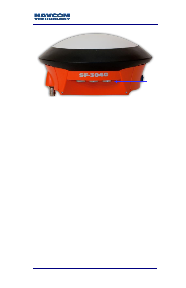
SF-3040 Antenna
The SF-3040 all-in-one housing incorporates
NavCom’s compact GNSS antenna (refer to Figure
32), with excellent tracking performance and a stable
phase center. The integrated antenna tracks L1, L2,
L2C, L5, G1, G2, and StarFire™ signals. The
Antenna Calibration Values for this product are
available from the National Geodetic Survey (NGS)
calibration table hyperlinked to this text.
2-61
Page 64

SF-3040 Product User Guide – Rev. F
SF-3040
integrated
antenna
Figure 32: SF-3040 Top View
See http://www.ngs.noaa.gov/cgi-
bin/query_cal_antennae.prl?Model=NAV for
specifications.
The robust housing assembly features a standard
5/8-inch BSW thread on the bottom of the receiver for
mounting the unit directly on a surveyor’s pole, tripod,
mast, or other industry-standard survey accessory,
and is certified to 70K feet (see Appendix B Antenna
Specifications, for restrictions).
Although rated to 70K feet, this antenna is not
designed for aircraft installations. Contact
sales@navcomtech.com for aircraft solutions.
Controller
The SF-3040 GNSS receiver is designed for use with
an external controller solution connected via one of
two serial COM ports or the Bluetooth port.
2-62
Page 65

SF-3040 Product User Guide – Rev. F
This may be accomplished using a PC, Tablet PC, or
Personal Digital Assistant (PDA) and a software
program that implements the rich control language
defined for NavCom GNSS products. Refer to the
user guide of your controller solution for further
information. NavCom lists several application
software solutions on our website:
http://www.navcomtech.com/Support/ApplicationSoftware.cfm
In addition, NavCom provides with the SF-3040 a
Windows™ based software utility, StarUtil 3000.
The StarUtil 3000 User Guide, PN 96-310008-3001,
is available online at
http://www.navcomtech.com/Support/DownloadCenter.cfm?categ
ory=manuals.
Antenna Phase Center Offsets
L2 – L1
Vertical: -10.4 mm
Horizontal: 2.4 mm
L5 – L1
Vertical: -6.0 mm
Horizontal: 1.8 mm
G1 – L1
Vertical: 5.0 mm
Horizontal: 1.0 mm
G2 – L1
Vertical: -9.6 mm
Horizontal: 3.0 mm
E6 – L1
Vertical: -10.7 mm
Horizontal: 3.0 mm
Absolute phase location in mm
Reference plane at unit mounting nut
L1: x=0.1, y=1.2, z=79.2
L2: x=-0.2, y=-1.1, z=89.6
2-63
Page 66

SF-3040 Product User Guide – Rev. F
L5: x=-0.2, y=-0.5, z=85.3
G1: x=-1.0, y=0.8, z=74.2
G2: x=0.1, y=-1.5, z=88.8
Applications
The SF-3040 GNSS receiver meets the needs of the
following applications:
Land Survey and GIS
Boundary Survey
Topographical Surveys in Rough Terrain
Construction Site Stake-out
High-Accuracy Data Collection for Post-Processing
Hydrographic Survey
NavCom lists several application software solutions
on our website:
http://www.navcomtech.com/Support/ApplicationSoft
ware.cfm
2-64
Page 67

SF-3040 Product User Guide – Rev. F
Chapter 3 ................................. Interfacing
This chapter details the SF-3040 GNSS receiver
connectors, LED display, appropriate sources of
electrical power, and how to interface to the
communication ports.
Battery Power
Two supplied removable Lithium-Ion battery packs
(PN 98-214946) provide power. Each of the two
battery packs is designed to last 3.5 hours, 7 hours
with both batteries, on a single charge with all GNSS
channels turned on (discharge time varies based on
environmental conditions and mode of operation).
With only L1, L2 and StarFire channels turned on,
each battery will last 4 hours, 8 hours with both
batteries. The smart battery interface allows the
batteries to be hot-swapped on the fly.
When battery 1 voltage is low, the receiver
automatically switches to battery 2 to provide
continuous power. For more information on the
battery packs, refer to the following:
Chapter 6, Batteries
Chapter 8, Safety Instructions
As long as the input voltage on the
external power connector is >9.0 V, the
power input will be from that connector
and the internal batteries will be in
standby mode. This is automatically
selected in the power input output (PIO)
hardware. If the unit does not have an
external power source and is running on
batteries, if an external power source is
connected, the PIO hardware
automatically switches to the external
3-65
Page 68

SF-3040 Product User Guide – Rev. F
Pin
Description
1
Return, black
2
Power Input 9, 9 to 30 VDC, 8W, red
power source and the battery switches
to standby mode.
If the voltage on the external power
connector drops below 9.0 V, the PIO
begins to draw some power from the
selected battery and the power draw
from that battery increases until the
external voltage decreases to about
8.3 V. At this point, the selected battery
will be supplying all of the power to the
PIO.
The selected battery is the one with the
lowest measured voltage when the PIO
is powered up or reset. This assures
that the one in standby mode is the
one with the most charge remaining so
that if the selected battery falls below
the threshold and the PIO switches to
the other battery, the user will have the
most time to replace or recharge the
discharged battery.
Electrical Power
A 2-pin LEMO female connector provides electrical
power to the SF-3040. It is located on the bottom of
the SF-3040 (refer to Figure 36). Pin assignments are
given in Table 3.
Table 3: External Power Cable Pin-Out
3-66
Page 69

SF-3040 Product User Guide – Rev. F
SF - 3040
Power Source
Ground
12
VDC
On/Off Button
Proper Shutdown of the SF-3040
Do either of the following to perform a proper
shutdown of the SF-3040:
Press and hold the On/Off button in the center of
the indicator panel (refer to Figure 33) for at least
two seconds. (There may be a delay of
approximately two seconds before the unit turns
off.)
Type [SHUTDOWN]HALT on the StarUtil 3000 (or
other) Input Terminal.
Figure 33: Indicator Panel On/Off Button
Do not unplug the LEMO end of
the optional unterminated power
cable, if one is being used, before
switching off power from the front
panel. The receiver may not
shutdown properly.
3-67
Page 70

SF-3040 Product User Guide – Rev. F
Part Number
Description
96-212172-01
DC power cable, unterminated, 10 ft
96-212178-01
Automotive DC power cable, with
cigarette lighter adapter
96-212171-01
Power AC/DC Adapter cable, 12 V,
18 W, 1.5 A
Color
Signal
Pin No
Black
Ground – Return1
1
Red
Power – Input
2
Figure 34: Proper External Power Source Setup
Power Cables
The SF-3040 can be powered by any of three
optional power cable types. Refer to Table 4 for
details. Refer to Table 5 for the pin assignments for
all power cables.
Table 4: Optional Power Cables
Table 5: Pin Assignments – All Power Cables
1
Wire size: AWG20 minimum
Current rating: < 2A
Figure 35: DC Power Cable P/N 96-212172-01
The SF-3040 receiver is protected from
reverse polarity with an inline diode. It
will operate on any DC voltage between
9 and 30 VDC, 6 W typical. The
recommended voltage is 12 Vdc.
3-68
(Optional)
Page 71

SF-3040 Product User Guide – Rev. F
Optional
Antenna
Mount
COM2
USB – COM1
Power
Pole
Mount
Voltages in excess of 30VDC will
damage the unit. The power
supply must be well-conditioned
with surge protection. Vehicular
electrical systems that create
voltage spikes in excess of 30VDC
will benefit from providing power
protection during vehicle engine
power-up. This can be
accomplished through a relay
power-on sequence and/or power
conditioning (such as a DC to DC
converter). Do not connect
equipment directly to the vehicle’s
battery without in-line protection
(such as a DC to DC converter).
Figure 36: SF-3040 Bottom View
3-69
Page 72

SF-3040 Product User Guide – Rev. F
Figure 37: Automotive DC Power Cable with
Cigarette Lighter Adapter P/N 96-212179-01
(Optional)
Figure 38: Universal AC-DC Power Adapter Cable
P/N 96-212171-01 (Optional)
Plug a standard American 2-prong power
cord into the power cable adapter. AC power
cords are available through small appliance
retailers (Radio Shack, Walmart, Best Buy,
etc.). AC power cords for non-110VAC
locales must be purchased locally.
Figure 39: AC Two-Prong Power Cord (optional, with
AC/DC adapter cable)
3-70
Page 73

SF-3040 Product User Guide – Rev. F
Communication Ports
The SF-3040 provides two communication ports –
one labeled USB and COM1 and the other COM2.
Table 6,
3-71
Page 74

SF-3040 Product User Guide – Rev. F
Table 7, and
3-72
Page 75

SF-3040 Product User Guide – Rev. F
DB9
Pin #
LEMO
Pin #
Pin Name
Pin Function
2 1 COM TDX
Serial port data from GNSS
board
3 2 COM1 RDX
Serial port data to GNSS board
5 3 GROUND
Ground
NC
4
USB D-
USB data - PIOB
NC
5
USB D+
USB data + PIOB
NC
6
USB ID
USB ID PIOB
NC
7
USB POWER
USB 5V power PIOB
Table 8 list the pin assignments for these ports.
Table 6: Pin Assignments – USB & COM1
Figure 40: COM2 Serial Cable P/N 96-212238-01
3-73
(Standard)
Page 76

SF-3040 Product User Guide – Rev. F
DB9
Pin #
LEMO
Pin #
Pin Name
Pin Function
2
1
COM2 TDX
RS-232 Serial port data from PIOB
3
2
COM2 RDX
RS-232 Serial port data to PIOB
5
3
GROUND
Ground
8
4
COM2 RTS
RS-232 Serial port flow control from
PIOB
7
5
COM2 CTS
RS-232 Serial port flow control to
PIOB
9
6
COM2 RING
RS-232 Ring signal to PIOB
Table 7: Pin Assignments – COM2
Supplied USB Device Cable
The USB Device Cable P/N 96-212169-01 is the
supplied 6ft (1.83m) data cable fitted with a LEMO
plug type and a USB A plug type, used to connect as
Device directly to a USB 2.0 connector. The pin
assignments are provided below.
Figure 41: USB Device Cable P/N 96-212169-01
The COM 1 Serial cable P/N 96-212170-01 is an
optional 6ft (1.83 m) data cable that can be plugged
directly into the COM1 port and used as an adjunct to
the USB Device Cable.
COM1 - USB is the only USB-
compliant port.
3-74
(Supplied)
Page 77

SF-3040 Product User Guide – Rev. F
USB
Pin #
LEMO
Pin #
Pin Name
Pin Function
4
3
Ground/Shield
Ground
2
4
USB D-
USB data -
3
5
USB D+
USB data +
NC
6
USB ID
USB ID
1
7
USB POWER
USB 5V power
Table 8: Pin Assignments – USB Device Cable Pin
Assignments (Supplied)
To turn the unit on, power must be in the
9 to 30 VDC range. Press and hold in
the I/O button for more than 3 seconds
(see Figure 33).
Voltages in excess of 30 VDC will
damage the unit. The power
supply must be well-conditioned
with surge protection. Vehicular
electrical systems that create
voltage spikes in excess of 30
VDC will benefit from providing
power protection during vehicle
engine power-up. This can be
accomplished through a relay
power-on sequence and/or power
conditioning (such as a DC to DC
converter). Do not connect
equipment directly to the vehicles
battery without in-line protection
(such as a DC to DC converter).
Unused pins are commonly missing from
cables. This is a typical cost-saving
practice of cable manufacturers.
3-75
Page 78

SF-3040 Product User Guide – Rev. F
Bluetooth Communications Setup
This section provides instructions to determine
Bluetooth Virtual COM port on a PC and to connect to
the SF-3040 via Bluetooth. Wireless connectivity is
provided within a range of 5 m (16 ft) once a
connection is established. The initial paring sequence
must be conducted within 2m (6ft) of the SF-3040.
1. Write down the SF-3040 serial number (from the
label on the receiver).
2. Turn on the SF-3040.
3. Plug the Bluetooth dongle (if one is being used1)
into the proper port on the PC.
1
Many laptops incorporate Bluetooth, but
not all will work; a dongle is an option.
Right-click the Bluetooth icon on the
Windows taskbar and select Explore My
Bluetooth Places from the pop-up menu
to open the My Bluetooth Places dialog
box (refer to Figure 42).
Double-click Search for devices in range
on the My Bluetooth Places dialog box to
display a list of the Bluetooth devices in
range (refer to Figure 42).
3-76
Page 79

SF-3040 Product User Guide – Rev. F
Figure 42: Search for Bluetooth Devices in Range
The naming convention for the SF-3040
is as follows:
product type, serial_num, rev_num.
Example: SF-3040,10280,2
4. Double-click SF-3040 in the Bluetooth device list.
A Bluetooth serial port icon for the selected
receiver is displayed (see Figure 48).
5. Double-click the Bluetooth serial port icon. A
graphic with green arrows indicates a connection
is established between the Bluetooth Virtual COM
port on the PC and the Bluetooth dongle.
If the PC requests a Bluetooth passcode,
click OK. There is no passcode for the SF3040 Bluetooth device; use the BTSET
command on the Input Terminal to create
or delete a passcode in the receiver.
Refer to the BTSET command in the
Sapphire Technical Reference Manual.
Not all Bluetooth devices are compatible
with the SF-3040. Refer to NavCom’s
Support/Troubleshooting Guides Web
page for additional information.
3-77
Page 80

SF-3040 Product User Guide – Rev. F
6. Double-click the Bluetooth serial port icon to
display the Bluetooth Serial Port dialog box (see
Figure 44), which confirms the configured COM
port.
7. Click OK.
8. To verify the assigned COM port, right-click the
Bluetooth serial port icon and select Properties on
the pop-up menu (the Bluetooth Properties dialog
box opens).
The Bluetooth Properties dialog box (refer to
Figure 43) displays the Bluetooth virtual COM port
assigned to the Bluetooth dongle. (Notate the
COM port number.)
3-78
Figure 43: Bluetooth Serial Port
Page 81

SF-3040 Product User Guide – Rev. F
Figure 44: Bluetooth Properties
9. Click OK on the Bluetooth Properties dialog box.
10. Open StarUtil 3000 on the PC.
11. Click the Connections button on the Shortcut bar
to open the Port Configuration dialog box (refer to
Figure 45).
The Bluetooth module can be in two
modes: Command Mode and Data Mode.
When in Data Mode, the module has an
active data connection with a connected
device; it does not receive commands
because commands would be interpreted
as data that need to be passed to the
connecting device.
Turning on Bluetooth is associated with a
software reset of the Bluetooth firmware,
so the system returns the same output as
when the [SHUTDOWN]REBOOT
command is issued (see details on the use
of the [SHUTDOWN] command in the
Sapphire Technical Reference Manual).
When Bluetooth is ON, another in-range
3-79
Page 82

SF-3040 Product User Guide – Rev. F
Bluetooth electronic device should be able
to detect the existence of the system.
Figure 45: Bluetooth Port Configuration
Refer to Figure 45 for the steps below:
12. Select Bluetooth as the Connection Type.
13. Select the appropriate COM Port (refer to Figure
49).
14. Click the Connect button to connect to the SF-3040.
15. Verify Bluetooth connectivity:
View the Bluetooth LED on the SF-3040 front panel
(refer to Table 9).
3-80
Page 83

SF-3040 Product User Guide – Rev. F
Icon
Indicator
Status
Description
Bluetooth
Off
Bluetooth off
Blue Blinking
Bluetooth on,
no connection
Blue
Bluetooth
connected
Table 9: Bluetooth Connectivity LED Indication
Type [PING] in the Input Terminal and click
the Send button. If properly connected, the
response is [PING]BT1 (refer to Figure 46).
Figure 46: Input Terminal – PING Command and
Response
To use an input terminal to determine
the Bluetooth Virtual COM port on a PC
and connect to the SF-3040 via
Bluetooth, refer to the BTSET message
in the Sapphire Technical Reference
Manual and to the section “Establish
Bluetooth via the Input Terminal” in the
StarUtil 3000 User Guide.
Logging Data to the Removable SD Card
Installing the SD Card
The SD card is located above the batteries in the
SF-3040 battery bay.
Follow these steps to set up the SD card:
1. To open the side chamber where the SD card slot
is located, hold the SF-3040 upright facing you
3-81
Page 84

SF-3040 Product User Guide – Rev. F
Release
Button
SD Slot
and press downward on the lower half (protruding
part) of the black release button on the left-hand
side of the SF-3040 (refer to Figure 47).
Figure 47: SD Card Chamber Release Button
2. Holding the SF-3040 upright, align the SD card
with the SD slot (refer to Figure 48), with the
lettering on the SD card facing downward.
Figure 48: SD Card Slot
3. Gently push the card into the slot.
3-82
Page 85

SF-3040 Product User Guide – Rev. F
Command
Operation
[LOGFILE]A:
Displays the current logging status of
drive A (SD card): ready, running1,
stopped, or paused
[LOGFILE]A:,
START2
Starts file logging on drive A (SD
card), if logging has not been started
[LOGFILE]A:,
FORCESTART
Forces file logging on drive A (SD
card) and ignores previous
CHKDSK.SD file state; overwrites
CHKDSK.SD file
[LOGFILE]A:,
PAUSE
Pauses file logging on drive A (SD
card)
[LOGFILE]A:,
STOP
Stops file logging on drive A (SD
card) if file logging is running or
paused
[LOGFILE]A:,
RESUME
Resumes file logging on drive A (SD
card) if file logging is paused
4. Close the chamber door and press until it is
securely closed (as verified by the latch click).
The receiver will support a SD card with
a maximum of 16GB (not included).
Logging Data to the Removable SD Card
Schedule the desired messages to log using the
[OUTPUT] command, with a port designation of
“FH1”. Refer to the Sapphire Technical Reference
Manual for detailed instructions.
On the Input Terminal, type the appropriate
commands (refer to Table 10).
When using the logging functions, allow a few
seconds between actions for the processor to
execute and the SD card to respond.
Table 10: Data Logging Input Commands
3-83
Page 86

SF-3040 Product User Guide – Rev. F
1
When the status is RUNNING or
PAUSED, the logged bytes are
displayed:
[LOGFILE]A: RUNNING 5245989
BYTES LOGGED
2
When the receiver is first turned on, or
when the USB mode is changed from
Mass Storage device mode to COM port
mode, the SD removable card is
reconfigured. If the user sends the
command [LOGFILE]A:,START before
the reconfiguration is finished, the
following message is output:
[LOGFILE]A: SD CARD IS BEING
MOUNTED, PLEASE WAIT
If the SDCARD message is turned on for this
port, the following [SDCARD] message is output:
[SDCARD] MOUNTING… 5
[SDCARD] MOUNTING… 6
[SDCARD] MOUNTING… 7
[SDCARD] MOUNTING…8
The numeral represents the SD card
mounting time in seconds. Upon
successful completion of mounting, data
logging starts.
If mounting fails, the following message
is output:
[LOGFILE]A: ERROR ON
MOUNTING SD CARD
If the SD card is not present and the
user sends the command
3-84
Page 87

SF-3040 Product User Guide – Rev. F
[LOGFILE]A:,START, the following
message is output:
[LOGFILE]A: SD CARD IS NOT
PRESENT
If the SD card is present and locked and
the user sends the command
[LOGFILE[A:,START, the following
message is output:
[LOGFILE]A: SD CARD IS LOCKED
Refer to the Sapphire Technical
Reference Manual [LOGFILE] command
for further essential notes regarding this
command.
Removing the SD Card
Follow these steps to remove the SD card from the
SF-3040:
1. Close any “open” files or the data will be lost.
2. Turn off power to the unit.
3. To open the battery chamber where the SD card
slot is located, hold the SF-3040 upright and
press downward (toward the ground) on the lower
half (protruding part) of the black button on the
battery chamber (refer to Figure 53).
4. Remove the battery packs (refer to Removing the
Battery Packs
5. Press in on the SD card and it will pop out enough
to grab it with the thumb and forefinger.
6. Gently pull out the SD card.
7. Reinstall the battery packs in the SF-3040 (refer
to All new batteries must be charged for a
minimum of 12 hours prior to use, regardless of
the LED indicator on the charger.
3-85
Page 88

SF-3040 Product User Guide – Rev. F
RTK
Power/
GNSS
Data
Link
StarFire
Bluetooth
Battery
Packs
Charge
Indicators
Power
Button
Installing the Battery Packs in the
SF-3040
8. Close the battery chamber door and press until it
clicks shut.
SF-3040 Indicator Panel LEDs
Figure 49: SF-3040 Indicator Panel
3-86
Page 89

SF-3040 Product User Guide – Rev. F
Icon
Indicator
Status
Description
RTK
Off
Radio power off or
RTK corrections not
being received
(other ports)
Green
Blinking
RTK corrections
being received (no
position fix)
Green
RTK corrections
being applied
(position fixed)
Red
Blinking
No RTK license
Icon
Indicator
Status
Description
Power/GNSS
Off
Power off
Red
Power on, but not
tracking
Green
Blinking
Acquiring or
tracking GNSS
satellites (no
position fix yet)
Green1
Position fixed
Figure 50: SF-3040 Indicator Panel, Detail
To power the unit on or off, depress the Power button
for more than 2 seconds. All LEDs illuminate for a
period of 3 to 5 seconds during power-up of the
GNSS receiver. Refer to Table 11 through Table 15
for detailed information on the Indicator Panel LEDs.
RTK LED
Table 11: RTK LED Indicator
Power/GNSS LED
3-87
Table 12: Power/GNSS LED Indicator
Page 90

SF-3040 Product User Guide – Rev. F
Icon
Indicator
Status
Description
Data
Link
Off
Power off or No data
output
Green
Blinking
Data I/O activity
Green
Data logging to
internal SD card
Red
Blinking
Data logging –
memory low
Red
Data logging – data
loss
Icon
Indicator
Status
Description
StarFire Link
Off
Power off
Red
No StarFire signal
Red
Blinking
No (or expired)
StarFire license1
Green
Blinking
Acquiring StarFire
signal
Green
Tracking StarFire
signal
1
The GNSS LED blinks at the PVT
positioning rate (1, 5, or 10 Hz).
Data Link LED
Table 13: Data Link LED Indicator
Bluetooth LED
Refer to Table 9.
StarFire LED
3-88
Table 14: StarFire LED Indicator
Page 91

SF-3040 Product User Guide – Rev. F
Icon
Indicator
Status
Description
Battery
Packs
Off
Power off or
batteries not
installed
Green
Battery pack has
sufficient charge
Red1
Battery pack is low
Red
2
Blinking
Both battery packs
are low
1
This LED blinks red until the receiver
navigates and can verify the license.
Battery Pack LED
An LED associated with each battery pack shows
that battery pack’s status.
Table 15: Battery Pack LED Indicator
3-89
1
When the battery pack indicator
changes from green to red, the unit
emits a 1-second warning beep.
2
When both battery packs are low or not
installed, the unit enters a power-down
warning period. During this period, both
battery LEDs blink red, and the unit
emits a series of 3 warning beeps of 1
second each followed by 10 seconds of
silence. This sequence is repeated 4
times. If either battery is replaced during
the warning period with a charged
battery pack, the new battery pack’s
status changes to green and the powerdown warning ceases. The power-down
warning also ceases if an external power
source is connected at this time.
Page 92

SF-3040 Product User Guide – Rev. F
Batteries are not charged in the unit. If
external power is applied, the battery
LEDs indicate the status of the batteries,
not the status of the external power
source.
Over-temperature Shutdown: The
SF-3040 emits a 5-second warning
beep, and all LEDs turn red to indicate
over- temperature condition and eminent
shutdown. This may be caused by
installed batteries and an internal
temperature exceeding 80°C (typically,
65°C ambient) for 5 seconds or longer.
This action is only to protect the
batteries and will not occur if batteries
are not installed.
3-90
Page 93

SF-3040 Product User Guide – Rev. F
This page is left blank intentionally.
3-91
Page 94

SF-3040 Product User Guide – Rev. F
Chapter 4 ................................. Installation
This chapter provides guidance on SF-3040 hardware
installation for optimum performance.
GNSS Receiver
The SF-3040 housing has a female 5/8-inch BSW
threaded mount (5/8-11 UNC) with a depth of 16 mm
(0.63 inch). Mount the SF-3040 on a surveyor’s pole,
tripod, mast, or any apparatus that accepts the thread
size.
Do not place the receiver in a
space where it may be exposed to
excessive heat, moisture, or
humidity.
There are no user-serviceable
parts inside the SF-3040 GNSS
receiver. Opening the unit
compromises the environmental
seal and voids the equipment
warranty.
4-92
The SF-3040 is not designed for
use on a moving vehicle. If
damage is sustained due to shock
or vibration while mounted on a
moving vehicle or if damage is
sustained due to shear, the
SF-3040 warranty is invalidated.
The SF-3050 is recommended for
use on a moving vehicle and
provides comparable performance
as it is based on the same GNSS
receiver technology.
Page 95

SF-3040 Product User Guide – Rev. F
Batteries
Refer to Chapter 6 for detailed information on
charging, installing, and maintaining the SF-3040
GNSS battery packs.
Integrated Antenna
Refer to Appendix B for detailed
specifications on the integrated antenna.
Antenna placement is critical to good system
performance. Avoid antenna shading by buildings,
rooftop structures, foliage, hills/mountains, etc.
Choose a mounting location with obstructions
as low as possible (preferably below the horizon),
where the antenna has a clear view of the sky, to
an elevation angle of 7º if possible. Obstructions
below 15º elevation generally are not a problem,
though this is dependent on satellite availability
for the local region.
Avoid placing the antenna where more than 90º
azimuth of the sky is obstructed. When more than
90º of azimuth is shaded, it is often still possible
for the receiver to navigate, however, poor satellite
geometry (due to satellite shading) will provide
poor positioning results. Even 10º of shading can
have a negative effect on performance, though
this generally is not the case.
Avoid placing the antenna on or near metal or
other electrically reflective surfaces.
Do not paint the antenna enclosure with a
metallic-based paint.
Avoid placing the antenna near electrical motors
(elevator, air conditioner, compressor, etc.)
Do not place the antenna too close to other active
4-93
Page 96

SF-3040 Product User Guide – Rev. F
antennae. The wavelength of L2 is 0.244m and
L1 is 0.19m. The minimum acceptable separation
between antennae is 1m (39 in), which provides
6dB of isolation. For 10dB of isolation, separate
the GNSS antennae by 2.5m, and for 13dB of
isolation (recommended) separate the antennae
by 5m.
Active antennae (those with LNA’s or amplifiers)
create an electrical field around the antenna.
These radiated emissions can interfere with other
nearby antennae. Multiple GNSS antennae in
close proximity to each other can create multipath
and oscillations between the antennae. These
add to position error or the inability to process the
satellite signals.
Most antennae have better gain when the satellite
is high in elevation. Expect tracking performance
to fade as the satellite lowers in elevation. It is not
unusual to see 10dB difference in antenna gain
(which translates into signal strength) throughout
the entire elevation tracking path.
Map obstructions above the horizon using a
compass and inclinometer. Use satellite prediction
software with a recent satellite almanac to assess
the impact on satellite visibility at that location
(available on NavCom’s web site).
A clear line of sight between the antenna and the
local INMARSAT satellite is required to track the
StarFire™ signal. INMARSAT satellites are geosynchronized 35,768kms above the Equator,
currently at Longitudes 15.5 West, 098 West,
142 West, 025 East, 109 East, and 143.5 East.
An inclination and bearing estimation tool is
available on NavCom’s website to aid in
determining potential obstructions to the StarFire™
signal.
4-94
Page 97

SF-3040 Product User Guide – Rev. F
Communication Port Connectivity
Connect the supplied LEMO 6-Pin connector of the
serial cable (PN 96-212169-01) COM 2 of the
SF-3040. Connect the DB9S end to the control
device.
In the Rover, the NMEA port is an output logical port
and may share the data physical port with RTCM,
CMR, or Sapphire GNSS RTK input corrections. In
the Base Station, the NMEA port should not share the
data port with any RTCM, CMR, or Sapphire GNSS
RTK output corrections as many NMEA-compatible
devices are likely to have parsing issues with the nonNMEA data.
Refer to the Sapphire Technical Reference Manual
for the available port configuration settings.
Figure 51: Communication Port Connections
4-95
Page 98

SF-3040 Product User Guide – Rev. F
Auxiliary Communication Module (Internal
UHF radio)
An optional 1-Watt internal, removable UHF radio is
available with the SF-3040. (Refer to Chapter 7 for
detailed information). The operational range of the
1W radio varies with the undulation of the
topography, the density of foliage and man-made
materials (i.e. buildings), the type of antenna
employed (NavCom offers a half-wave antenna), and
the height of the base antenna. A broadcast range of
2km is not uncommon, but will vary greatly based on
the operating environment. If a longer range is
desired, NavCom offers a 35W radio option.
Basics of RTK Surveying
RTK (Real-Time Kinematic) is a GNSS system that
yields very accurate 3D position fixes immediately in
real-time.
The Network RTK software option allows
the receiver to generate and receive
RTCM 1000-series messages. The
navigation algorithms are designed to
support single-base correction
configurations. Network adjusted RTK
formats are not currently supported.
A reference station (base station) transmits its GNSS
position to roving receivers as the base receiver
generates them. The roving receivers use the
reference station readings to differentially correct their
own positions. Accuracies of a few centimeters in all
three dimensions are possible. RTK requires
multi-frequency GNSS receivers and high-speed
radio modems.
4-96
Page 99

SF-3040 Product User Guide – Rev. F
Proper setup of a reference station minimizes GNSS
errors in the rover. The reference GNSS receiver is
set up at a known surveyed location. With this
position locked in, it transmits its code, clock, and
reference station coordinates information to the
roving receiver(s). The roving receiver(s) use this
information to correct each GNSS measurement
received.
If the receiver will be used or transported above
40,000 ft (12.2 km), it must be located in a
pressurized compartment.
The SF-3040, when configured as a reference
station, can transmit corrections to any number of
roving receivers capable of picking up the radio signal
and decoding one of these correction formats:
NavCom proprietary, RTCM 2.3/3.1 for Network RTK,
CMR, or CMR+. The signal can be received in less
than ideal environments, though some data loss may
occur.
Setup of the reference station receiver above the
roving receivers is recommended to enable
transmission to all rovers in all directions with minimal
obstruction. High- frequency radio signals generally
travel a shorter distance than lower-frequency signals
and do not penetrate obstructions as well over
distance.
Refer to Chapter 8, RTK Setup, in the StarUtil 3000
User Guide for detailed instructions.
4-97
Page 100

SF-3040 Product User Guide – Rev. F
Chapter 5 ............................... Configuration
The SF-3040 has a rich interface and detailed control
language, allowing each unit to be individually
programmed to a specific application.
There are essentially 3 methods available to
configure and control the SF-3040:
1. StarUtil 3000 – This program is a NavComdeveloped utility designed to configure and view
many (but not all) of the SF-3040 functions. In
addition to its setup capabilities, StarUtil 3000 can
capture and log data, upload new software and
licenses to the internal processor, and query and
display various receiver performance functions.
Though it is developed as an Engineering tool, it
has its own place in the commercial market as
well. The program is provided on the SF-3040
Product USB Flash Drive.
2. 3rd party controller – Some manufacturers have
already integrated NavCom’s control features in
their bundled hardware and software solution kits
in a variety of applications including GIS, Machine
Control, Aerial Photogrammetry, Land &
Oceanographic Survey, Agriculture, and Military
products. Information on these applications is
available from the NavCom web site and
customer service.
3. User Program – Users may develop unique
operating programs to control the SF-3040
(potentially in conjunction with other devices or
utilities). To facilitate this effort, NavCom provides
the Sapphire Technical Reference Manual (TRM).
Information on this tool is available from the
NavCom Web site and customer service.
5-98
 Loading...