

Page 1
S
6
-
23-
F--
S
F
2
1
1
2
1
GGPPSS PPrroodduuccttss
UUsseerr GGuuiidde
1
0
0
e
NavCom Technology, Inc.
20780 Madrona Avenue
Torrance, California 90503 USA
Tel: +1 310.381.2000
Fax: +1 310.381.2001
sales@navcomtech.com
www.navcomtech.com
P/N: 9
3100
3001
Page 2

SF-2110 User Guide – Rev. C
This page is left blank intentionally
Page 3

SF-2110 User Guide – Rev. C
Table of Contents
List of Figures..........................................................iv
List of Tables ............................................................ v
Notices ...........................................................vi
Copyright....................................................................vi
Trademarks ................................................................vi
FCC Notice................................................................ vii
User Notice................................................................ vii
Limited Warranty ....................................................... vii
StarFire Licensing™..................................................viii
USG FAR....................................................................ix
Global Positioning System ......................................... ix
Revision History........................................................x
Use of this Document..............................................xi
Related Documents........................................................xi
SF-2110 Quick Start Guide........................................xi
StarUtil-2110 User Guide...........................................xi
SF-2110 Technical Reference Manual...................... xii
RINEXUtil User Guide...............................................xii
Integrators Toolkit...................................................... xii
NavCom Release Notes............................................ xii
Related Standards.........................................................xiii
ICD-GPS-200 ............................................................xiii
RTCM-SC-104...........................................................xiii
CMR, CMR+..............................................................xiii
NMEA-0183...............................................................xiii
Publicly-Operated SBAS Signals ..............................xiii
RTCA/DO-229D....................................................xiii
WAAS (Wide Area Augmentation System).......... xiv
EGNOS (European Geostationary Navigation
Overlay Service)................................................... xiv
MSAS (MTSAT Satellite-based Augmentation
System)................................................................xiv
GAGAN (GPS Aided Geo Augmented
Navigation)........................................................... xiv
Chapter 1 Introduction .....................................15
System Overview...........................................................15
GPS Sensor System .................................................15
Accuracy....................................................................16
Features … Applies to All Models.............................16
i
Page 4

SF-2110 User Guide – Rev. C
Output Data Rate ......................................................16
NCT Binary Proprietary Data.....................................17
NMEA-0183 Data......................................................17
Models...........................................................................18
SF-2110M..................................................................18
SF-2110R..................................................................18
Bluetooth ...................................................................19
Antennae .......................................................................20
Standard....................................................................20
L-band (option – SF-2110R only)..............................20
Controller.......................................................................21
Included Items...........................................................22
Applications...............................................................24
Unique Features............................................................25
Chapter 2 Interfacing........................................ 27
Electrical Power.........................................................27
Communication Ports................................................31
*Event........................................................................35
*1 PPS.......................................................................36
Indicator Panel...............................................................37
Chapter 3 Installation....................................... 41
Standard Antenna .....................................................41
L-Band Antenna (SF-2110R Only)............................43
GPS Sensor...............................................................44
Block Diagrams.........................................................45
Communication Port Connectivity.............................47
GPS Antenna Connector...........................................48
Chapter 4 Configuration ..................................51
Factory Default Output Messages.................................53
Message Descriptions...............................................53
Message Descriptions...............................................55
3rd Party Controller Configuration Settings...............56
Chapter 5 Safety Instructions.......................... 57
Transport...................................................................57
Maintenance..............................................................57
External Power Source..............................................57
Safety First ................................................................58
A GPS Module Specifications.............................59
Features ....................................................................59
Time-To-First-Fix.......................................................60
Dynamics...................................................................60
Measurement Performance.......................................61
ii
Page 5

SF-2110 User Guide – Rev. C
User programmable output rates...............................61
Data Latency .............................................................62
*1PPS........................................................................62
Connector Assignments............................................62
Input/Output Data Messages.....................................63
LED Display Functions (Default)...............................63
Satellite Based Augmentation System Signals.........63
Physical and Environmental......................................64
B Antenna Specifications ....................................65
Radiation Pattern.......................................................67
Radiation Pattern.......................................................71
C StarFire ..........................................................73
Description.................................................................73
Infrastructure .............................................................74
Reliability...................................................................75
How to Access the StarFire Service..............................77
D *Event Input Configuration...............................79
E CE Declara tion of Conformity..........................81
Glossary ..........................................................83
iii
Page 6

SF-2110 User Guide – Rev. C
List of Figures
Figure 1: SF-2110 Supplied Equipment .................. 22
Figure 2: Universal Power Adapter.......................... 28
Figure 3: AC Power Cord ........................................ 28
Figure 4: Power Cable Pin Assignment...................29
Figure 5: SF-2110 Front View With Bluetooth......... 33
Figure 6: SF-2110 Front View Without Bluetooth.... 33
Figure 7: NavCom Serial Cable...............................34
Figure 8: NavCom Serial Cable Pin Assignment.....34
Figure 9: SF-2110M Back View...............................35
Figure 10: SF-2110R Back View.............................35
Figure 11: Indicator Panel – With Bluetooth............ 37
Figure 12: Indicator Panel – Without Bluetooth....... 37
Figure 13: Standard GPS/L-band Antenna.............. 41
Figure 14: SF-2110 Base Plate Dimensions Without
Mounting Brackets.................................. 44
Figure 15: SF-2110 Base Plate Dimensions With
Mounting Brackets.................................. 45
Figure 16: SF-2110M Block Diagram......................46
Figure 17: SF-2110R Block Diagram....................... 46
Figure 18: Communication Port Connections..........47
Figure 19: StarUtil-2110 Rover Navigation Setup ... 56
Figure 20: PN: 82-001017-0001LF Antenna
Dimensions............................................. 66
Figure 21: 82-001017-0001LF Radiation Pattern.... 67
Figure 22: PN: 82-001018-0001LF Antenna
Dimensions (SF-2110R only).................69
Figure 23: PN: 82-001018-0001LF Mounts............. 70
Figure 24: Pipe Mount Adapter for L-band SF-2110R
Antenna.................................................. 70
Figure 25: 82-001018-0001LF Radiation Pattern.... 71
Figure 26: StarFire Network .................................... 78
Figure 27: *Event Cable Wiring Diagram................. 79
Figure 28: *PPS & Event Latch Configuration......... 80
Figure 29: *Event Latch Output Rate Configuration 80
Figure 30: DTE to DCE RS-232 Pin Assignments... 86
iv
Page 7

SF-2110 User Guide – Rev. C
List of Tables
Table 1: Supplied Equipment...................................23
Table 2: External Power Cable Pin-Out...................27
Table 3: Optional DC Pwr Cable Pin Assignments..29
Table 4A: Port A Serial Cable Pin-Outs...................32
Table 4B: Port B Serial Cable Pin-Outs...................32
Table 5: GPS LED Indication...................................38
Table 6: StarFire Link LED Indication (Default) .......38
Table 7: Data I/O Active LED Indication ..................39
Table 8: Bluetooth Connectivity LED Indication.......39
Table 9: Acceptable Cable Lengths.........................49
Table 10: Factory Default NCT Binary Messages....53
Table 11: Factory Default NMEA Messages............55
Table 12: 82-001017-0001LF Standard Antenna ....65
Table 13: L-band SF-2110R Antenna......................68
Table 14: *Event Wiring Connections......................79
v
Page 8

SF-2110 User Guide – Rev. C
Notices
SF-2110 GPS Products User Guide
P/N 96-310023-3001
Revision C
September 2008
Serial Number:
Date Delivered:
Purchased From:
Copyright
© 2008 by NavCom Technology, Inc.
All rights reserved. No part of this work or the
computer program(s) described herein may be
reproduced, stored, or transmitted by any means,
without the expressed written consent of the copyright
holders. Translation in any language is prohibited
without the expressed written consent of the copyright
holders.
Trademarks
‘find your way’, ‘NavCom Globe’ and ‘NAVCOM
TECHNOLOGY’ logos are trademarks of NavCom
Technology, Inc. StarFire™ is a registered trademark
of Deere & Company. All other product and brand
names are trademarks or registered trademarks of
their respective holders.
vi
Page 9

SF-2110 User Guide – Rev. C
FCC Notice
This device complies with Part 15 Subpart B Class B
of the FCC Rules. Operation is subject to the
following two conditions:
1. This device may not cause harmful
interference, and
2. This device must accept any interference
received, including interference that may
cause undesired operation.
User Notice
NavCom Technology, Inc. shall not be responsible for
any inaccuracies, errors, or omissions in information
contained herein, including, but not limited to,
information obtained from third party sources, such as
publications of other companies, the press, or
competitive data organizations.
This publication is made available on an “as is” basis
and NavCom Technology, Inc. specifically disclaims
all associated warranties, whether express or implied.
In no event will NavCom Technology, Inc. be liable for
direct, indirect, special, incidental, or consequential
damages in connection with the use of or reliance on
the material contained in this publication, even if
advised of the possibility of such damages. NavCom
Technology, Inc. reserves the right to make
improvements or changes to this publication and the
products and services herein described at any time,
without notice or obligation.
Limited Warranty
NavCom Technology, Inc., warrants that its products
will be free from defects in workmanship at the time of
delivery. Under this limited warranty, parts found to
be defective or defects in workmanship will be
vii
Page 10

SF-2110 User Guide – Rev. C
repaired or replaced at the discretion of NavCom
Technology, Inc., at no cost to the Buyer, provided
that the Buyer returns the defective product to
NavCom Technology, Inc. in the original supplied
packaging and pays all transportation charges,
duties, and taxes associated with the return of the
product. Parts replaced during the warranty period
do not extend the period of the basic limited warranty.
This provision does not extend to any NavCom
Technology, Inc. products, which have been
subjected to misuse, accident or improper installation,
maintenance or application, nor does it extend to
products repaired or altered outside the NavCom
Technology, Inc. production facility unless authorized
in writing by NavCom Technology, Inc.
This provision is expressly accepted by the buyer in
lieu of any or all other agreements, statements or
representations, expressed or implied, in fact or in
law, including the implied warranties of
merchantability and fitness for a particular purpose
and of all duties or liabilities of NavCom Technology,
Inc. To the buyer arising out of the use of the goods,
and no agreement or understanding varying or
extending the same will be binding upon NavCom
Technology, Inc. unless in writing, signed by a dulyauthorized officer of NavCom Technology, Inc.
This limited warranty period is one (1) year from date
of purchase.
StarFire Licensing™
The StarFire signal requires a subscription that must
be purchased in order to access the service. Licenses
are non-transferable, and are subject to the terms of
the StarFire Signal License agreement. For further
details on the StarFire Signal Network, its capabilities,
terms and conditions visit www.navcomtech.com
send an email inquiry to sales@navcomtech.com
viii
or
Page 11

SF-2110 User Guide – Rev. C
USG FAR
Technical Data Declaration (Jan 1997)
The Contractor, NavCom Technology, Inc., hereby
declares that, to the best of its knowledge and belief,
the technical data delivered herewith under
Government contract (and subcontracts, if
appropriate) are complete, accurate, and comply with
the requirements of the contract concerning such
technical data
Global Positioning System
Selective availability (S/A code) was disabled on 02
May 2000 at 04:05 UTC. The United States
government has stated that present GPS users use
the available signals at their own risk. The US
Government may at any time end or change
operation of these satellites without warning.
The U.S. Department of Commerce Limits
Requirements state that all exportable GPS products
contain performance limitations so that they cannot
be used to threaten the security of the United States.
Access to satellite measurements and navigation
results will be limited from display and recordable
output when predetermined values of velocity and
altitude are exceeded. These threshold values are far
in excess of the normal and expected operational
parameters of the SF-2110 GPS Sensor.
ix
Page 12

SF-2110 User Guide – Rev. C
Revision History
Added Bluetooth description, specs,
text, new photos of front panel with
Bluetooth icon, and new block
diagrams to include Bluetooth
Rev C (Sept 2008)
Rev B (May 2008)
Revised Included Items
Added note that StarFire Satellite
Locations & IDs may change after
September 19, 2008
Removed references to 44 message
FCC Notice revised;
CE Declaration of Conformity
added as Appendix E
RTCA/DO-229C standard updated
to RTCA/DO-229D; MSAS &
GAGAN added to the organizations
implementing the standard
ITRF2000 updated to ITRF2005 (Apr
08) as reference for StarFire position
outputs
Added data to the Accuracy section
in Chapter 1
Added Caution to Chapter 2:
Functionality Rules: Interaction of
Front Panel On/Off Switch & Ignition
Pin
Updated text and graphics pertaining
to StarFire -- new satellite uplink
sites
Updated Specs in Appendix A:
Measurement Performance –
Updated Velocity from
0.01 m/s to 0.03 m/s
Updated StarFire Position (V)
Accuracy from <75cm to < 1m
Updated IPPS Accuracy from 15ns
to 50ns
Rev A (Dec. 2007) Initial release
x
Page 13
SF-2110 User Guide – Rev. C
Use of this Document
This User Guide is intended to be used by someone
familiar with the concepts of GPS and satellite
surveying equipment.
Note indicates additional information
to make better use of the product.
This symbol means Reader Be
Careful. Indicates a caution, care,
and/or safety situation. The user might
do something that could result in
equipment damage or loss of data.
This symbol means Danger. You are in
a situation that could cause bodily
injury. Before you work on any
equipment, be aware of the hazards
involved with electrical and RF circuitry
and be familiar with standard practices
for preventing accidents.
Revisions to this User Guide can be obtained in a
digital format from
http://www.navcomtech.com/Support/
Related Documents
SF-2110 Quick Start Guide P/N 96-310031-3001
Provides instructions to quickly set up the standard
configuration of the SF-2110.
StarUtil-2110 User Guide P/N 96-310027-3001
xi
Page 14

SF-2110 User Guide – Rev. C
Describes the operation and use of NavCom’s
Windows based control program (included on CD).
SF-2110 Technical Reference Manual P/N 96-312006-3001
Describes the control and output data message
formats utilized by this instrument (for customer
programming purposes; included on CD).
RINEXUtil User Guide P/N 96-310021-2101
Describes the conversion program used on NavCom
proprietary output data message formats to RINEX
ver 2.10 observation and navigation files (for
customer programming purposes; included on CD).
Integrators Toolkit
Provides additional instruction and tools for
developing control programs for this instrument (not
included in the packaging material; contact
support.navcomtech.com
for a copy).
NavCom Release Notes
Describes software updates for NavCom products.
Current and archived Release Notes are available on
the NavCom web site:
http://www.navcomtech.com/Support/DownloadCente
r.cfm?category=releasenotes.
NavCom Customer Support provides software
updates described in the Release Notes. Submit a
request for software updates via the Request Support
web page.
xii
Page 15

SF-2110 User Guide – Rev. C
Related Standards
ICD-GPS-200
NAVSTAR GPS Space Segment / Navigation User
Interfaces Standard. ARINC Research Corporation;
2250 E. Imperial Highway; El Segundo, California
90245
RTCM-SC-104
Recommended Standards For Differential GNSS
Service. Radio Technical Commission For Maritime
Services; 1800 N. Kent St, Suite 1060; Arlington,
Virginia 22209
CMR, CMR+
Compact Measurement Record; Trimble Navigation
Limited; 935 Stewart Drive; Sunnyvale, CA 94085
NMEA-0183
National Marine Electronics Association Standard For
Interfacing Marine Electronic Devices. NMEA
National Office; 7 Riggs Avenue; Severna Park,
Maryland 21146
Publicly-Operated SBAS Signals
RTCA/DO-229D
The Radio Technical Commission for Aeronautics
(RTCA) develops consensus-based
recommendations regarding communications,
navigation, surveillance, and air traffic management
(CNS/ATM) system issues.
RTCA. 1828 L Street, NW, Suite 805, Washington,
DC 20036.
xiii
Page 16

SF-2110 User Guide – Rev. C
These organizations implement the RTCA/DO-229D
standard set by RTCA:
WAAS (Wide Area Augmentation System)
U.S. Department of Transportation. Federal Aviation
Administration. 800 Independence Ave, SW,
Washington, DC 20591
EGNOS (European Geostationary Navigation Overlay Service)
European Space Agency. 8, 10 rue Mario-Nikis,
F-75738 Paris Cedex 15, France.
MSAS (MTSAT Satellite-based Augmentation System)
Japan Civil Aviation Bureau. Ministry of Transport.
Kasumigaseki 2-1-3, Chiyoda-ku, Tokyo 100, Japan.
GAGAN (GPS Aided Geo Augmented Navigation)
Indian Space Research Organization. Antariksh
Bhavan, New Bel Road, Bangalore - 560 094, India.
xiv
Page 17
SF-2110 User Guide – Rev. C
1
Chapter 1 ..............................Introduction
System Overview
GPS Sensor System
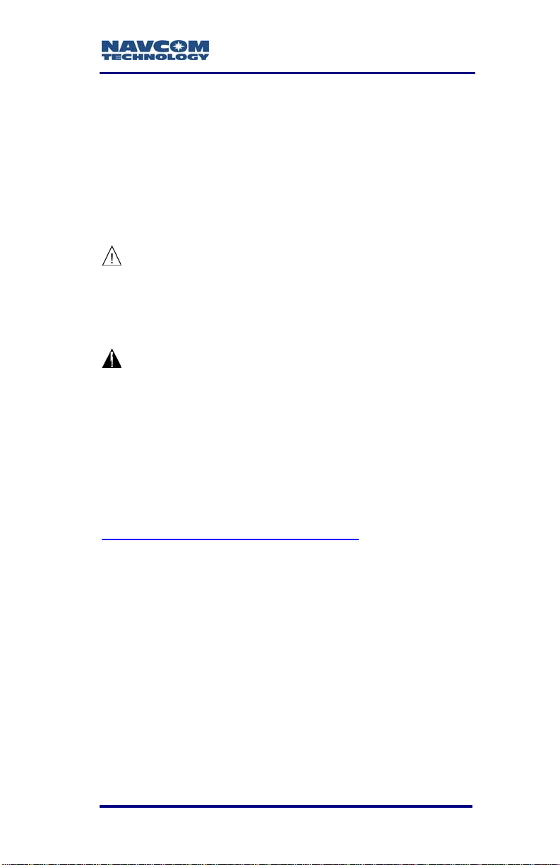
The SF-2110 GPS
sensor delivers
unmatched accuracy
to the precise
positioning community.
This unique receiver is
designed to use NavCom’s StarFire
is a worldwide Satellite Based Augmentation System
(SBAS) for half meter level position accuracy (postconvergence period). The receiver is also capable of
RTCM code and DGPS operating methods. The
operating software is also capable of supporting an
external radio modem.
1
network, which
The SF-2110 integrated sensor consists of:
9 14-channel, L1-frequency, precision GPS receiver
9 2 separate SBAS channels, RTCA/DO-229D
compliant (WAAS/EGNOS/MSAS/GAGAN)
1
9 StarFire
L-Band receiver
There are two models, the SF-2110M and the
SF-2110R. Packaging and performance standards of
the models are the same; the differences lie in the
features, as described later in this chapter. Only
SF-2110 sensors with the Bluetooth icon on the front
indicator panel are Bluetooth capable (see Figure 11).
The system also includes a wide-band antenna with a
built-in LNA and other interconnection accessories
outlined in Table 1, later in this chapter.
Subscription Required
* Consult Release Notes on the NavCom web site for availability. 1-15
Page 18

SF-2110 User Guide – Rev. C
1
Accuracy
The system provides <50cm position accuracy (postconvergence
1
period) when StarFire correction
signals on the WAAS grid are used, <1m off the
WAAS grid.
System accuracy with WAAS, EGNOS,
MSAS, or GAGAN signals is subject to the
quality and update rate of these publiclyoperated signals. Refer to Related
Standards\Publicly-Operated SBAS
Signals for contact information regarding
the organizations that implement the
RTCA/DO-229D standard.
The system provides <1m position accuracy, when
WAAS, EGNOS, MSAS, or GAGAN (RTCA/DO-229D
compliant) SBAS correction signals are used.
The system provides <1m position accuracy, when
dGPS code correction signals are used.
Features … Applies to All Models
Output Data Rate
Both SF-2110 models can output proprietary raw data
at programmable rates from <
rates up to 10Hz
2
and Position Velocity Time (PVT)
data at programmable rates from <
predetermined rates up to 10Hz
1Hz to predetermined
1Hz to
2
through two 115kbps
RS-232 serial ports with less than 100ms latency.
<
50cm horizontal and <75cm vertical accuracy are
maintained as each output is independently calculated
based on an actual GPS position measurement, as
opposed to an extrapolation/interpolation between
1Hz measurements.
See Glossary or Web-site;2Separate Software Option Required
1-16 * Consult Release Notes on the NavCom web site for availability.
Page 19

SF-2110 User Guide – Rev. C
NCT Binary Proprietary Data
The sensor can output proprietary raw data
containing information including (but not limited to):
9 Satellite Ephemeris (0x81)
9 Raw Pseudorange Measurements (0xB0)
9 Position, Height, & Time (0xB1)
9 Velocity & Heading (0xB1)
9 Signal to Noise (0x86)
9 Channel Status (0x86)
9 Correction Data (mirror data; 0xEC)
9 *Event/Marker
9 Measurement Quality (0xB1 and 0xB5)
These data can be integrated in real-time positioning
applications or post-processed against any number of
software applications designed to handle NCT or
RINEX raw data. The SF-2110 Technical Reference
Manual (TRM) is included on the CD with the
SF-2110 and is also available on NavCom’s website.
The TRM describes the attributes of each of the
input/output records (see Related Documents in the
fore-matter).
NMEA-0183 Data
The SF-2110 is capable of outputting several
standard NMEA-0183 data strings (see Related
Standards in the fore-matter). Each data string is
headed with GP.
Standard:
9 *ALM – GPS Almanac Data
9 GBS – GNSS Satellite Fault Detection
* Consult Release Notes on the NavCom web site for availability. 1-17
Page 20

SF-2110 User Guide – Rev. C
9 GGA – GPS Fix Data
9 GLL – Geographic Position – Lat / Lon
9 GSA – GNSS DOP & Active Satellites
9 GST – GNSS Pseudorange Error Statistics
9 GSV – GNSS Satellites In View
9 RMC – Recommended Minimum Specific GNSS
Data
9 VTG – Course Over Ground & Ground Speed
9 ZDA – Time & Date
Models
SF-2110M
This model utilizes a compact dual-band antenna
capable of receiving GPS and StarFire signals. This
antenna provides excellent phase center stability in a
small, robust, lightweight format.
The model is ideal for vehicle mounting to suit a wide
variety of machine guidance and control applications
in: GIS (Geographic Information Systems) data
collection, and Nautical Stationkeeping.
It is equipped with additional features allowing
interconnectivity with a variety of antennas and other
instrumentation to suit specific applications and
configurations.
SF-2110R
The SF-2110R is similar to SF-2110M, except that it
includes a separate L-Band antenna
(PN: 82-001018-0001LF) for enhanced StarFire
1-18 * Consult Release Notes on the NavCom web site for availability.
Page 21

SF-2110 User Guide – Rev. C
signal reception in challenging environments such as
high geographic latitude.
Both the GPS antenna port (ANT 1) and
the StarFire antenna port (ANT 2 -
SF-2110R only) provide 5.0VDC. Care
must be taken to select an appropriately
rated GPS antenna if the standard
NavCom antenna is not used.
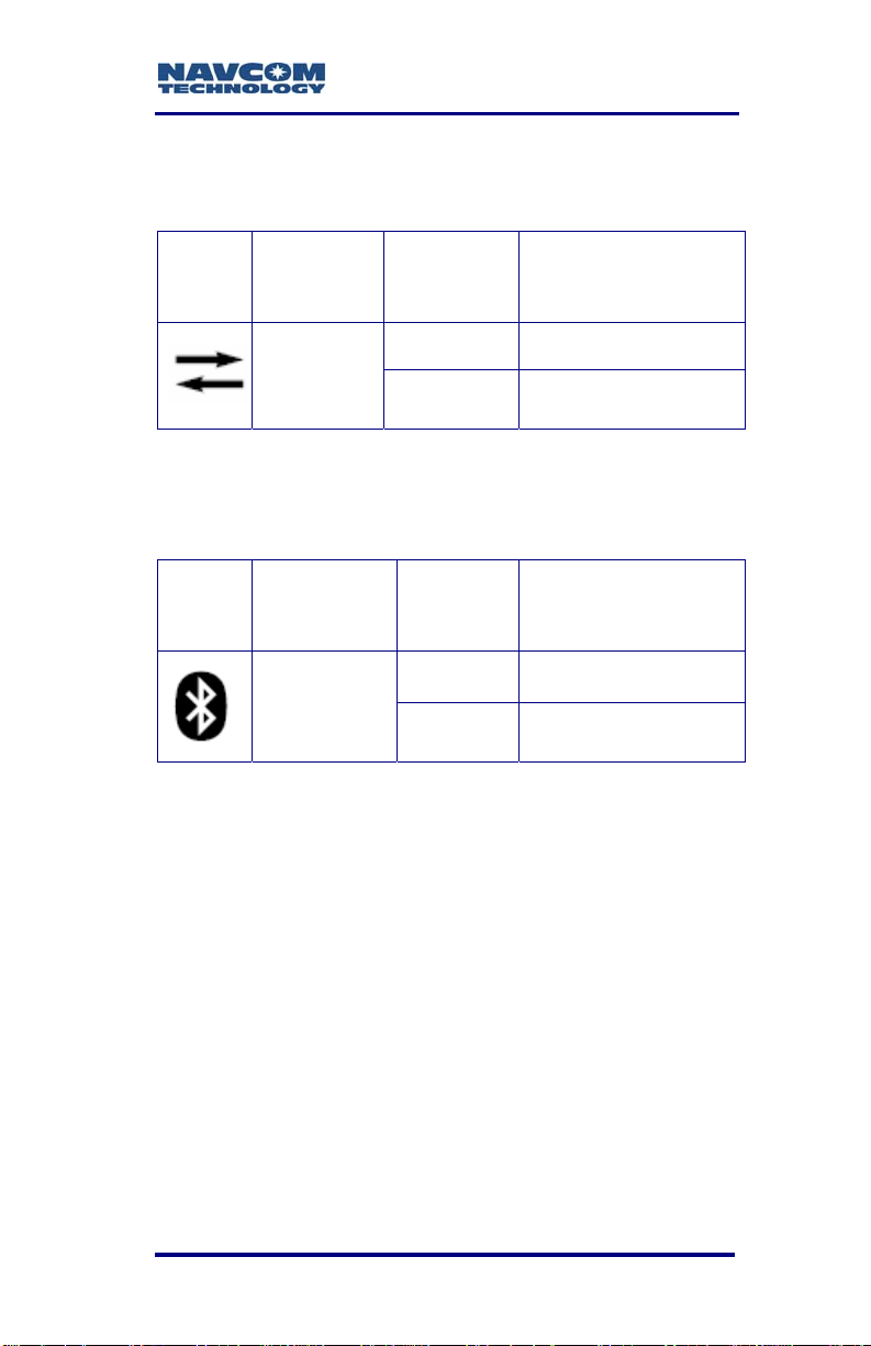
Bluetooth
Only SF-2110M and SF-2110R sensors with the
Bluetooth icon on the front indicator panel are
Bluetooth capable (see Figure 11). The Bluetooth
module permits cableless operation between the
sensor and a Bluetooth equipped controller. Wireless
connectivity is provided within a range of 10 meters
(32 feet). The Bluetooth module contains Bluetoothcertified components, and is FCC and CE certified.
Refer to the StarUtil-2110 User Guide
for instructions to setup Bluetooth
communications via the supplied NavCom
software utility, StarUtil-2110, (see Related
Documents in the fore-matter).
* Consult Release Notes on the NavCom web site for availability. 1-19
Page 22
SF-2110 User Guide – Rev. C
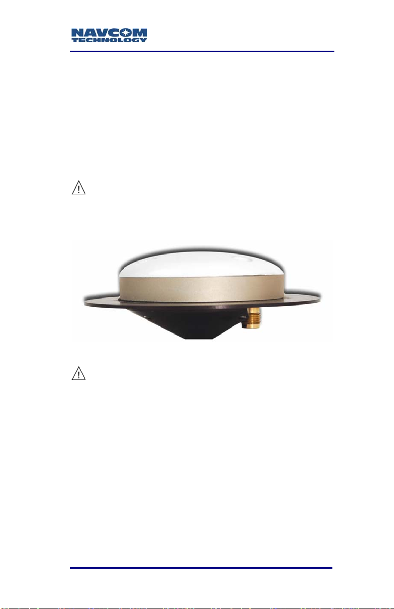
Antennae
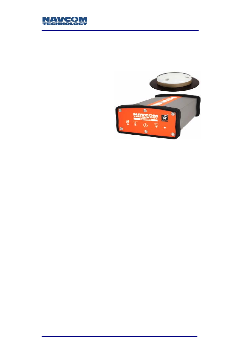
Standard
The standard integrated
antenna
(PN: 82-0010170001LF)
tracks all GPS, WAAS/EGNOS and StarFire signals.
Our compact GPS antenna has excellent tracking
performance and a stable phase center for GPS L1.
The robust housing assembly features a standard
5/8” BSW thread for mounting directly to a surveyor’s
pole, tripod, or mast and is certified to 70,000 feet
(see Specifications for restrictions).
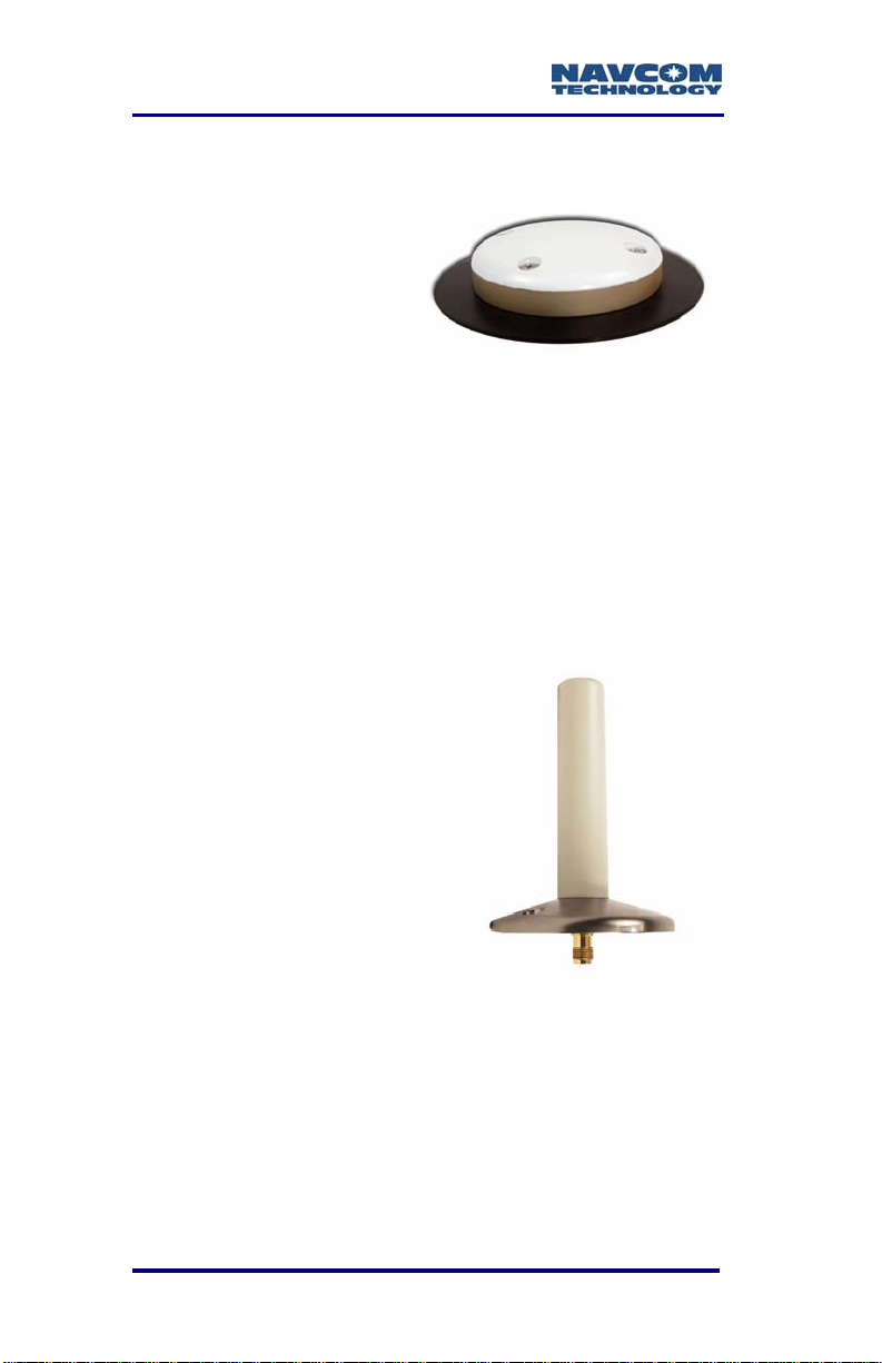
L-band (option – SF-2110R only)
The L-band antenna
(PN: 82-001018-0001LF)
tracks StarFire signals. This
antenna has excellent
tracking performance of
geostationary satellites for
latitudes furthest from the
equator. The robust housing
assembly features a flat
mounting surface with three
mounting holes and a 3m
coaxial cable with TNC
connectors. The L-Band antenna comes with a pipe
mount adapter for one inch diameter pipes (see
Figure 24). The SF-2110R uses the SF-2110M GPS
antenna to receive the GPS and WAAS/EGNOS
signals.
1-20 * Consult Release Notes on the NavCom web site for availability.
Page 23

SF-2110 User Guide – Rev. C
Controller
The SF-2110 GPS sensor is designed for use with an
external controller solution connected via one of two
serial ports or Bluetooth.
This may be accomplished using a PC, Tablet PC or,
Personal Digital Assistant (PDA) and a software
program which implements the rich control language
defined for NavCom GPS products. Refer to the
user’s guide of the controller solution for further
information. NavCom lists several application
software solutions on our website:
http://www.navcomtech.com/Support/ApplicationSoftware.cfm
In addition, NavCom provides a Windows™ based
software utility, called StarUtil-2110, with the receiver.
The StarUtil-2110 User Guide, P/N 96-310027-3001,
is available on-line at
http://www.navcomtech.com/Support/DownloadCenter.cfm?categ
ory=manuals.
* Consult Release Notes on the NavCom web site for availability. 1-21
Page 24
SF-2110 User Guide – Rev. C
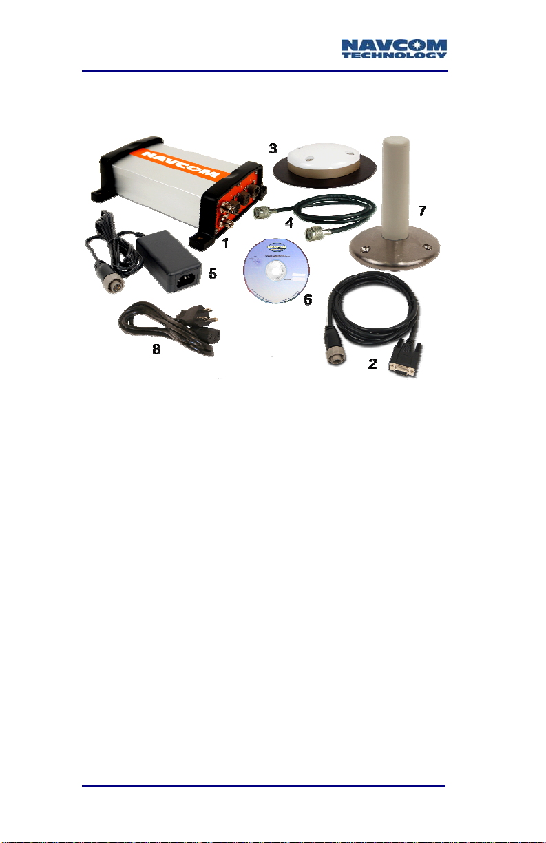
Included Items
Figure 1: SF-2110 Supplied Equipment
1-22 * Consult Release Notes on the NavCom web site for availability.
Page 25

SF-2110 User Guide – Rev. C
Table 1: Supplied Equipment
SF-2110 GPS Sensor
1
(SF-2110M P/N 92-310367-3002LF)
(SF-2110R P/N 92-310367-3001LF)
Positronic 9-Pin to DB9S Data Cable, 6 ft
2
(P/N 94-310260-3006LF)
L1/L-Band GPS Antenna, Patch
3
(P/N 82-001017-0001LF)
GPS Antenna Cable, 12 ft (x2, SF-2110R only)
4
(P/N 94-310261-3012LF)
Positronic 9-Pin Universal AC/DC Power Adapter
5
12VDC, 1.25A
(P/N 82-020005-3001LF )
CD-Rom containing User Guides, brochures,
6
software utilities, and technical papers.
(P/N 96-314001-3001)
L-Band GPS Antenna, Helix (SF-2110R only)
7
(P/N 82-001018-0001LF)
8 North American 3-Pin AC power Cord, 10 ft
Mounting Bracket {Shown with GPS Sensor}
9
(P/N 88-310408-3001LF)
Shipping Carton with Label {Not Shown}
10
(P/N 79-200303-0001)
SF-2110 User’s Guide {Not Shown}
11
(P/N 96-310023-3001 - included on supplied CD)
SF-2110 Quick Start Guide {Not Shown}
12
(P/N 96-310031-3001 Hard Copy)
Pipe Mount Adapter for L-Band GPS Antenna, Helix
13
(SF-2110R only) {see Figure 24}
* Consult Release Notes on the NavCom web site for availability. 1-23
Page 26

SF-2110 User Guide – Rev. C
Applications
The rugged and reliable SF-2110 GPS series is
designed for productivity with minimal setup time. The
SF-2110 series is ideal for mounting to suit a variety
of machine guidance and control applications as well
as for use in backpack GIS and mapping applications.
The primary operation mode uses the StarFire
service, and offers half-meter accuracy for immediate
results in the field (post-convergence period); great
for navigation and relocation of existing assets. The
two SBAS channels provide free GPS RTCA/DO229D compliant corrections (WAAS/EGNOS/MSAS/
GAGAN), which coupled with NavCom’s enhanced
SBAS algorithm typically provide sub-meter real-time
accuracy. The receiver also provides sub-meter
accuracy using RTCM DGPS code corrections from
sources such as USCG beacons (additional
equipment required).
Simply connect the controller solution to an available
port and receive NMEA format position information, or
use a NavCom partner controller solution for
additional configuration and monitoring capabilities.
The SF-2110 GPS sensors meet the needs of a large
number of applications including, but not limited to:
9 Land Survey / GIS
9 Nautical Stationkeeping
9 Asset Location
9 Hydrographic Survey
9 Photogrammetric Survey
9 Machine Control
9 Railway, Ship and Aircraft Precise Location
Several application software solutions are listed on
the NavCom website at:
http://www.navcomtech.com/Support/ApplicationSoft
ware.cfm
1-24 * Consult Release Notes on the NavCom web site for availability.
Page 27

SF-2110 User Guide – Rev. C
1
Unique Features
The SF-2110 GPS sensor has many unique features:
StarFire
1
The ability to receive NavCom’s unique StarFire
correction service is fully integrated within each unit.
A single set of corrections can be used globally
enabling a user to achieve half-meter level positioning
accuracy without the need to deploy a separate base
station, thus saving time and capital expenditure.
StarFire position outputs are referenced to the
ITRF2005 datum (Apr 08).
Positioning Flexibility
The SF-2110 is capable of using WAAS, EGNOS,
MSAS, GAGAN (RTCA/DO-229D compliant) code
corrections via two internal Satellite Based
Augmentation System (SBAS) channels. The
SF-2110 automatically configures to use the most
suitable correction source available and changes as
the survey dictates (this feature can be overridden).
Data Sampling
1Hz std, 5 and 10Hz Optional
GPS L1 raw measurement data is output up to 1Hz in
the standard configuration. An optional upgrade
allows 5 and 10Hz raw measurement data via either
of the two serial ports.
The PVT (Position, Velocity, & Time) data is output at
up to 1Hz in the standard configuration. An optional
upgrade allows 5 and 10Hz position updates for
highly dynamic applications.
Separate Software Option Required
* Consult Release Notes on the NavCom web site for availability. 1-25
Page 28

SF-2110 User Guide – Rev. C
GPS Performance
The SF-2110 utilizes a precision GPS engine, which
incorporates several patented innovations. The
engine’s industry leading receiver sensitivity provides
more than 50% signal to noise ratio advantage over
competing technologies. This results in improved real
time positioning, proven through independent tests,
when facing various multipath environments.
Rugged Design
Units have been tested to conform to MIL-STD-810F
for low pressure, solar radiation, rain, humidity, saltfog, sand, and dust.
The rugged design of the SF-2110 system
components provides protection against the harsh
environments common to areas such as construction
sites, offshore vessels, and mines.
1-26 * Consult Release Notes on the NavCom web site for availability.
Page 29

SF-2110 User Guide – Rev. C
Chapter 2 .................................Interfacing
This chapter details the SF-2110 GPS sensor
connectors, LED display, appropriate sources of
electrical power, and how to interface the
communication ports.
Electrical Power
A rear panel 9-pin Positronic male connector provides
electrical power to the SF-2110. Pin assignments are
given in Table 2; see Figure 4 for pin location on the
connector.
Table 2: External Power Cable Pin-Out
Pin Signal Color
1 *1PPS Out Blue
2 Ignition Brown
3 *Event Yellow
4 Power Input Orange
5 Power Return Black
6 Power Input Red
7 Not Used Green
8 Not Used Violet
9 Signal GND Gray
* Consult Release Notes on the NavCom web site for availability. 2-27
Page 30
SF-2110 User Guide – Rev. C
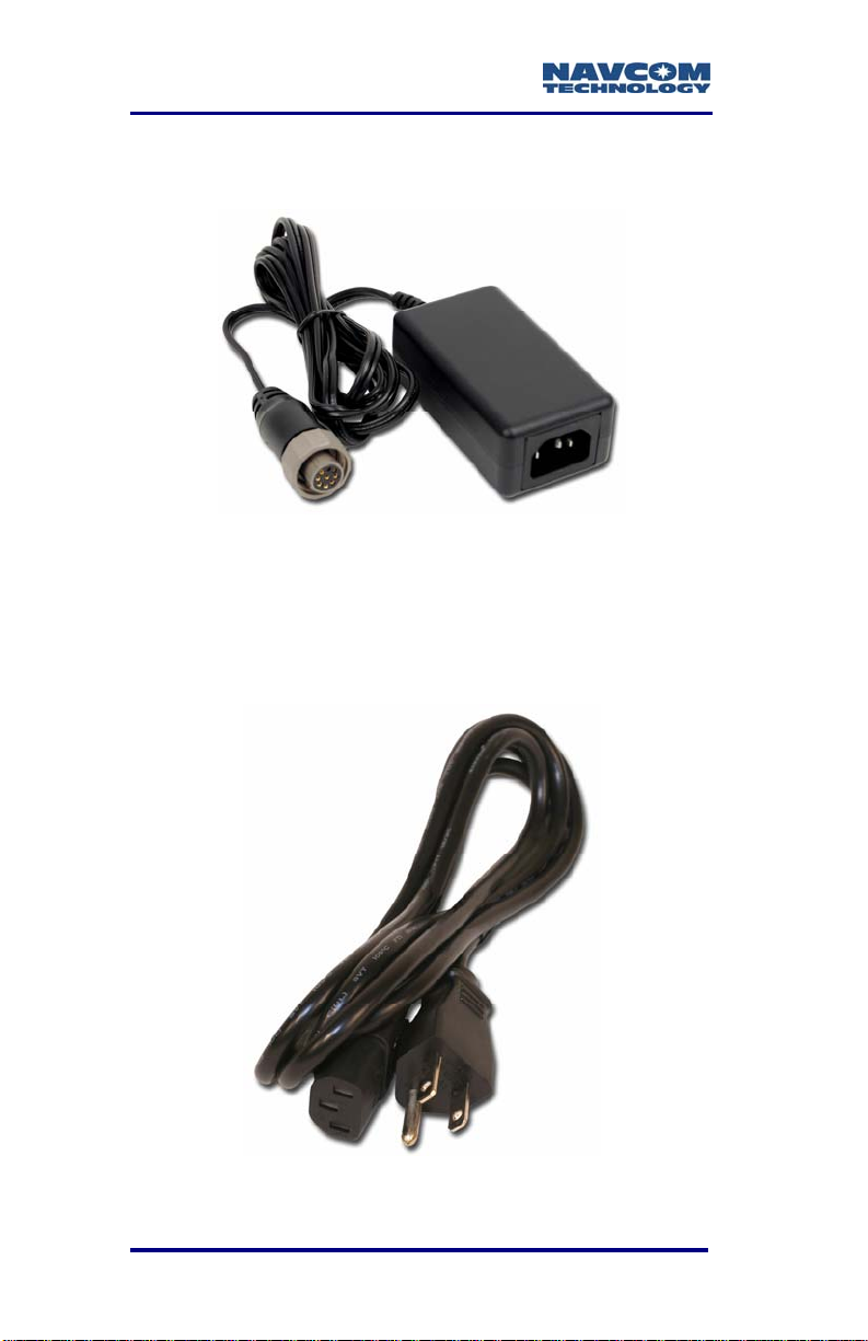
The SF-2110 is supplied with a universal AC/DC,
12V, 1.25A power adapter (P/N 82-020005-3001LF).
Figure 2: Universal Power Adapter
Replacement AC power cords are
available through electronics retailers
(Radio Shack, Walmart, Best Buy,
etc.)
Figure 3: AC Power Cord
2-28 * Consult Release Notes on the NavCom web site for availability.
Page 31
SF-2110 User Guide – Rev. C
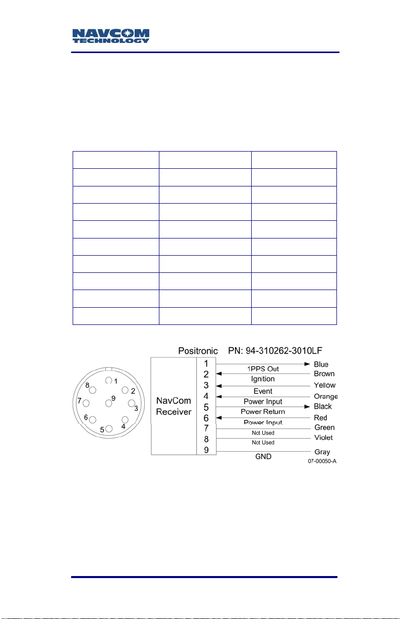
P/N 94-310262-3010LF is an optional 10ft (3m)
unterminated power cable fitted with a Positronic plug
type, used to connect directly to a DC source. The
wiring color code and pin assignments are labeled on
the cable assembly and provided below.
Table 3: Optional DC Power Cable Pin Assignments
Color Signal Pin No
Blue *1PPS Out 1
Brown Ignition 2
Yellow *Event 3
Orange Power Input 4
Black Power Return 5
Red Power Input 6
Green Not Used 7
Violet Not Used 8
Gray GND 9
Figure 4: Power Cable Pin Assignment
* Consult Release Notes on the NavCom web site for availability. 2-29
Page 32

SF-2110 User Guide – Rev. C
The GPS sensor is protected from reverse polarity
with an inline diode. It will operate on any DC voltage
between 9 and 36 VDC, 5 watts (maximum).
Voltages less than 9VDC will turn the
unit off. To turn the unit on, power
must be in the 9 to 36 VDC range.
Press and hold the I/O switch in for
more than 3 seconds.
Voltages in excess of 36VDC will
damage the unit. The power supply
must be well conditioned with surge
protection. Vehicular electrical systems
which create voltage spikes in excess
of 36VDC will benefit from providing
power protection during vehicle engine
power-up. This can be accomplished
through a relay power-on sequence
and/or power conditioning (such as a
DC to DC converter). Do not connect
equipment directly to the vehicles
battery without in-line protection (such
as a DC to DC converter).
Functionality Rules: Interaction of Front
Panel On/Off Switch & Ignition Pin
9 If the unit is powered off from the front panel
On/Off switch (see Figure 5):
• Applying +7VDC or greater to the
Ignition pin (see Figure 4) turns the
unit on
• Removing power from the Ignition pin
turns the unit off
9 If the unit is turned on from the front panel On/Off
switch, the Ignition pin is over-ridden and will not
function.
2-30 * Consult Release Notes on the NavCom web site for availability.
Page 33

SF-2110 User Guide – Rev. C
9 If the unit is turned off from the Ignition pin, the
front panel On/Off switch is over-ridden and will
not function.
9 If the unit is turned on from the Ignition pin and
the user wishes to use the On/Off switch for future
on/off procedures, the unit must be turned off from
the front panel On/Off switch.
Communication Ports
The SF-2110 provides two 9-pin female Positronic
connector communication ports labeled Port A and
Port B located at the back of the sensor, as shown in
Figure 9. Each conforms to the EIA RS232 standard
with data rates from 4.8 to 115.2Kbps. The connector
pin-outs are described in Table 4A and 5B. The
supplied interface data cable (P/N 94-3102603006LF) is constructed as described in Figure 8. The
SF-2110 is configured as a DCE device. Laptop and
desktop computers are configured as DTE devices,
therefore a straight-through cable provides proper
connectivity (PC TXD pin 2 connects to SF-2110 RXD
pin 2).
New models of the SF-2110 provide Bluetooth
wireless connectivity within a range of 10 meters (32
feet). Only SF-2110 sensors with the Bluetooth icon
on the front indicator panel are Bluetooth capable
(see Figure 11). The Bluetooth module contains
Bluetooth-certified components. The data rate for
Bluetooth communications is 230.4Kbps.
* Consult Release Notes on the NavCom web site for availability. 2-31
Page 34

SF-2110 User Guide – Rev. C
Table 4A: Port A Serial Cable Pin-Outs
(P/N 94-310260-3006LF)
Positronic
Pins
Signal Nomenclature
[DCE w/respect to DB9]
1 Not connected 2 Not connected 3 *1PPS 8
4 RXD RS-232 3
5 TXD RS-232 2
6 Not connected 7
7 Not connected 8 Not connected 9 GND 5
Table 4B: Port B Serial Cable Pin-Outs
(P/N 94-310260-3006LF)
Positronic
Pins
Signal Nomenclature
[DCE w/respect to DB9]
1 Not connected 2 Not connected -
DB9S
Pins
DB9S
Pins
3 RD+ RS-422 8
4 RXD RS-232 / RD- RS-422 3
5 TXD RS-232 / TD- RS-422 2
6 TD+ RS-422 7
7 Not connected 8 Not connected 9 GND 5
2-32 * Consult Release Notes on the NavCom web site for availability.
Page 35

Power/GPS
Status
Figure 5: SF-2110 Front View With Bluetooth
StarFire
Status
On/Off
SF-2110 User Guide – Rev. C
Data I/O
Activity
Bluetooth
Connectivity
Power/GPS
Status
StarFire
Status
On/Off
Data I/O
Activity
Figure 6: SF-2110 Front View Without Bluetooth
* Consult Release Notes on the NavCom web site for availability. 2-33
Page 36

SF-2110 User Guide – Rev. C
Figure 7: NavCom Serial Cable P/N 94-310260-
3006LF
PN: 94-310260-3006LF
Positronic
1
2
3
4
8
9
5
NavCom
7
Receiver
6
Port A / Port B
1
2
1PPS / RD+ RS-422
3
RD RS-232 / RD- RS-422
4
5
TD RS-232 / TD- RS-422
6
NC / TD+ RS-422
7
8
GND / GND
9
Figure 8: NavCom Serial Cable Pin Assignment
DB9S
07-00048-E
1
2
3
4
5
6
7
8
9
2-34 * Consult Release Notes on the NavCom web site for availability.
Page 37

SF-2110 User Guide – Rev. C
TNC Connector 1
L1/StarFire Antenna
Figure 9: SF-2110M Back View
TNC Connector 1
L1 Antenna
Port A
RS232
Power
Port
Port B
RS232/422
(switchable)
Power
Port
TNC Connector 2
Optional Separate
StarFire Helix
Antenna
Port A
RS232
Port B
RS232/422
(switchable)
Figure 10: SF-2110R Back View
*Event
The SF-2110 accepts an event input pulse to
synchronize external incidents requiring precise GPS
time tagging, such as aerial photography. For
example, the action of a camera’s aperture creates
an input pulse to the Event port. The SF-2110 outputs
* Consult Release Notes on the NavCom web site for availability. 2-35
Page 38

SF-2110 User Guide – Rev. C
position and time information relative to each
photograph taken.
Specifications:
9 50 Ohm input impedance
9 3Vdc > Input Voltage, High < 6Vdc
9 0Vdc < Input Voltage, Low < 1.2Vdc
9 Minimum pulse width, 100nsec
9 Rising or Falling edge Synchronization
Connecting the shared EVT MKR port requires a nine
pin, cable fitted with a Positronic plug, NavCom
P/N 94-310262-3010LF.
An *event latch interface unit may be
necessary if the input device pulse is
unable to drive the input.
Detailed specifications of the Event
Input, cable wiring, and configuration
may be found in Appendix D of this
User Guide.
*1 PPS
A pulse is available from the SF-2110 at an output
rate of once per second. This pulse can be used for a
variety of Time/Mark applications where relative
timing is required.
Specifications:
9 15ns relative accuracy
9 Better than 100ns absolute accuracy
9 50 Ohm, TTL level
9 Pulse width, default 100mS, range 10 – 999mS
9 Pulse delay, default 0mS, range 0 – 999mS
9 Rising or Falling Edge Synchronization
2-36 * Consult Release Notes on the NavCom web site for availability.
Page 39
SF-2110 User Guide – Rev. C
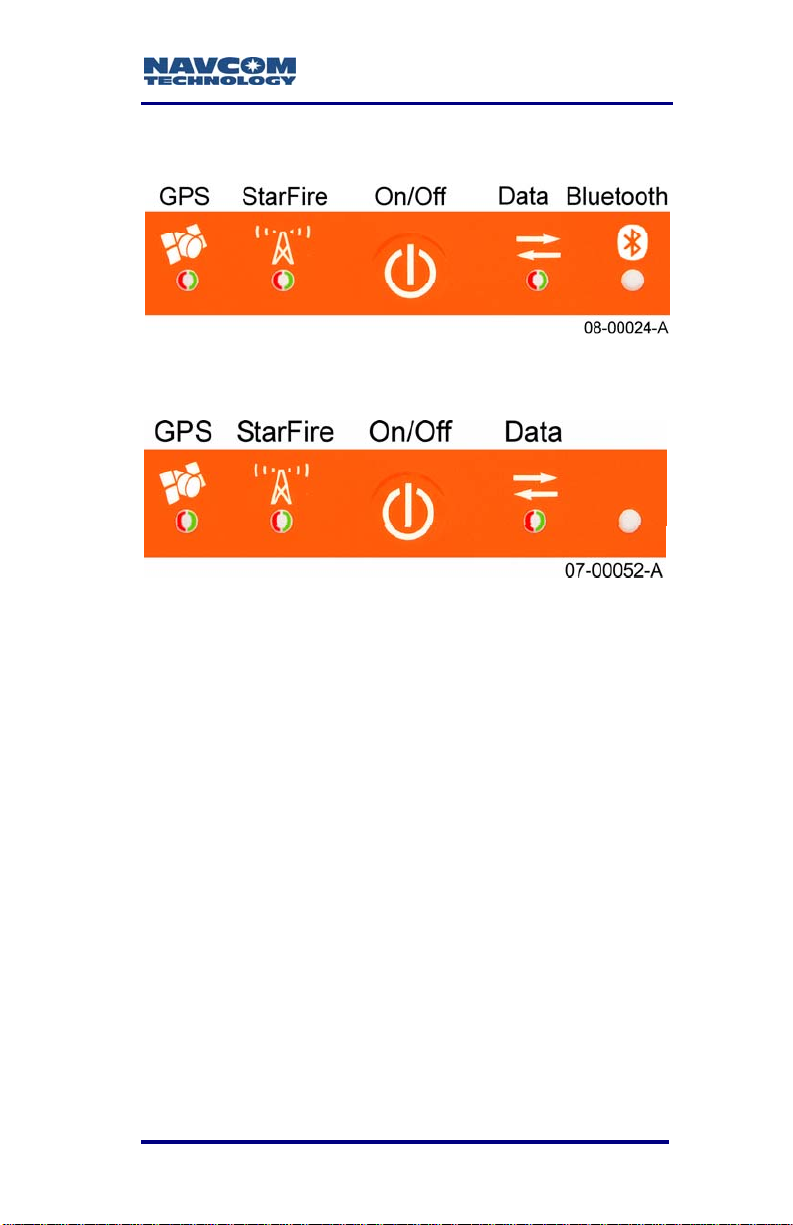
Indicator Panel
Figure 11: Indicator Panel – With Bluetooth
Figure 12: Indicator Panel – Without Bluetooth
The indicator panel provides a quick status view of
the GPS navigation/operating mode, StarFire signal
strength, the On/Off (I/O) switch, and, in new models,
Bluetooth connectivity, respectively.
To power the unit on or off, depress the I/O switch for
more than 3 seconds. All LEDs illuminate for a period
of 3-5 seconds during power-up of the GPS sensor.
Refer to the Functionality Rules on page 2-30
for details on powering on/off the unit.
* Consult Release Notes on the NavCom web site for availability. 2-37
Page 40

SF-2110 User Guide – Rev. C
GPS LEDs
Table 5: GPS LED Indication
Icon
Indicator Status Description
Off
Power on but not
Acquiring GPS
(no nav 2D/3D fix yet)
Tracking GPS
satellites (nav fix)
Power/GPS
Red
Green
Blinking
Green
The GPS LEDs blink at the PVT
positioning rate (1, 5, or 10Hz)
StarFire Link LEDs
Table 6: StarFire Link LED Indication (Default)
Icon
Indicator Status Description
No StarFire signal
No StarFire License
Acquiring StarFire
signal
Tracking StarFire
signal
StarFire
Link
Red
Red
Blinking
Green
Blinking
Green
Power off
tracking
satellites
2-38 * Consult Release Notes on the NavCom web site for availability.
Page 41
Data I/O Active LEDs
Table 7: Data I/O Active LED Indication
SF-2110 User Guide – Rev. C
Icon
Indicator Status Description
No data output
Data I/O active
Data
Red
Green
Blinking
Bluetooth Connectivity LEDs
Table 8: Bluetooth Connectivity LED Indication
Icon
Indicator Status Description
Red
Bluetooth
Blue
No Bluetooth
connection
Bluetooth
connection active
* Consult Release Notes on the NavCom web site for availability. 2-39
Page 42

SF-2110 User Guide – Rev. C
This page is left blank intentionally
2-40 * Consult Release Notes on the NavCom web site for availability.
Page 43
SF-2110 User Guide – Rev. C
Chapter 3 .................................Installation
This chapter provides guidance on hardware
installation for optimum performance.
Standard Antenna
The 5/8 inch BSW threaded antenna mount has a
depth of 16mm (0.63 inch).
The BSW insert is secured in-place with an
adhesive, and its removal will change the
shock and vibration sustainability
characteristics of the antenna mount.
Figure 13: Standard GPS/L-band Antenna
Do not loosen or remove the Phillips screws
on the base of the antenna for mounting
purposes. This will VOID the warranty and
compromise the environmental seal of the
antenna, leading to internal damage.
9 Antenna placement is critical to good system
performance. Avoid antenna shading by buildings,
rooftop structures, foliage, hills/mountains, etc.
9 Locate the antenna where it has a clear view of
the sky, to an elevation angle of 7º if possible.
Obstructions below 15º elevation generally are
not a problem, though this is dependent on
satellite availability for the local region.
* Consult Release Notes on the NavCom web site for availability. 3-41
Page 44

SF-2110 User Guide – Rev. C
9 Avoid placing the antenna where more than 90º
azimuth of the sky is obstructed. When more than
90º of azimuth is shaded, it is often still possible
for the reciever to navigate, however, poor
satellite geometry (due to satellite shading) will
provide poor positioning results. Even 10º of
shading can have a negative effect on
performance, though this generally is not the
case.
9 Avoid placing the antenna on or near metal or
other electrically reflective surfaces.
9 Do not paint the antenna enclosure with a
metallic-based paint.
9 Avoid placing the antenna near electrical motors
(elevator, air conditioner, compressor, etc.)
9 Do not place the antenna too close to other active
antennas. The wavelength of L1 is 0.19m. The
minimum acceptable separation between
antennas is 1m (39 in), which provides 6dB of
isolation. For 10dB of isolation, separate the GPS
antennas by 2.5m (8ft), and for 13dB of isolation
(recommended) separate the antennas by
5m (16ft).
9 Active antennas (those with LNA’s or amplifiers)
create an electrical field around the antenna.
These radiated emissions can interfere with other
nearby antennas. Multiple GPS antennas in close
proximity to each other can create multipath and
oscillations between the antennas. These add to
position error or the inability to process the
satellite signals.
9 Most antenna’s have better gain when the satellite
is high in elevation. Expect tracking performance
to fade as the satellite lowers in elevation. It is not
unusual to see 10dB difference in antenna gain
3-42 * Consult Release Notes on the NavCom web site for availability.
Page 45

SF-2110 User Guide – Rev. C
(which translates into signal strength) throughout
the entire elevation tracking path.
9 Map obstructions above the horizon using a
compass and inclinometer. Use satellite prediction
software with a recent satellite almanac to assess
the impact on satellite visibility at that location
(available on NavCom’s website).
9 A clear line of sight between the antenna and the
local INMARSAT satellite is required to track the
StarFire signal. INMARSAT satellites are geosynchronized 35,768kms above the Equator,
currently at Longitudes 15.5° West, 098° West,
142° West, 025° East, 109° East, and 143.5°
East. An inclination and bearing estimation tool is
available on NavCom’s website to aid in
determining potential obstructions to StarFire
signal.
StarFire Satellite locations and IDs may
change after September 19, 2008, as
replacement satellites are brought into
service for aging satellites.
L-Band Antenna (SF-2110R Only)
The separate L-band antenna for the SF-2110R is
used in high latitude applications and most frequently
on marine vessels. This is an active antenna,
meaning it has a built-in LNA. Therefore, this antenna
should have good isolation from other near-frequency
antennae. The best practice is to follow the same
precautions as the standard GPS antenna. On
platforms with many antenna systems, it is better to
locate the standard GPS antenna closer to the
wheelhouse, but out of the radar or satcom beam
path and the L-band antenna high on the mast. For
best performance, do not allow more than 7dB of
cable loss between the antenna and the receiver.
* Consult Release Notes on the NavCom web site for availability. 3-43
Page 46

SF-2110 User Guide – Rev. C
Applications at high latitudes without the L-band
antenna should mount the GPS antenna high on the
mast, with the same considerations for beam path
avoidance and cable loss limitations.
GPS Sensor
Mount the SF-2110 GPS sensor to a flat surface.
Shock isolators suitable for 1.8kg (4lbs) may be
necessary for environments with high vibration, i.e.
Earth moving equipment or aircraft installation.
The SF-2110 can be installed in a backpack for
mobile surveying applications.
Do not place the sensor in a confined space or where
it may be exposed to excessive heat, moisture, or
humidity.
There are no user serviceable parts
inside the SF-2110 GPS sensor.
Removing the screws that secure the
front end and rear end plates will void
the equipment warranty.
Figure 14: SF-2110 Base Plate Dimensions
Without Mounting Brackets
3-44 * Consult Release Notes on the NavCom web site for availability.
Page 47

SF-2110 User Guide – Rev. C
Figure 15: SF-2110 Base Plate Dimensions
With Mounting Brackets
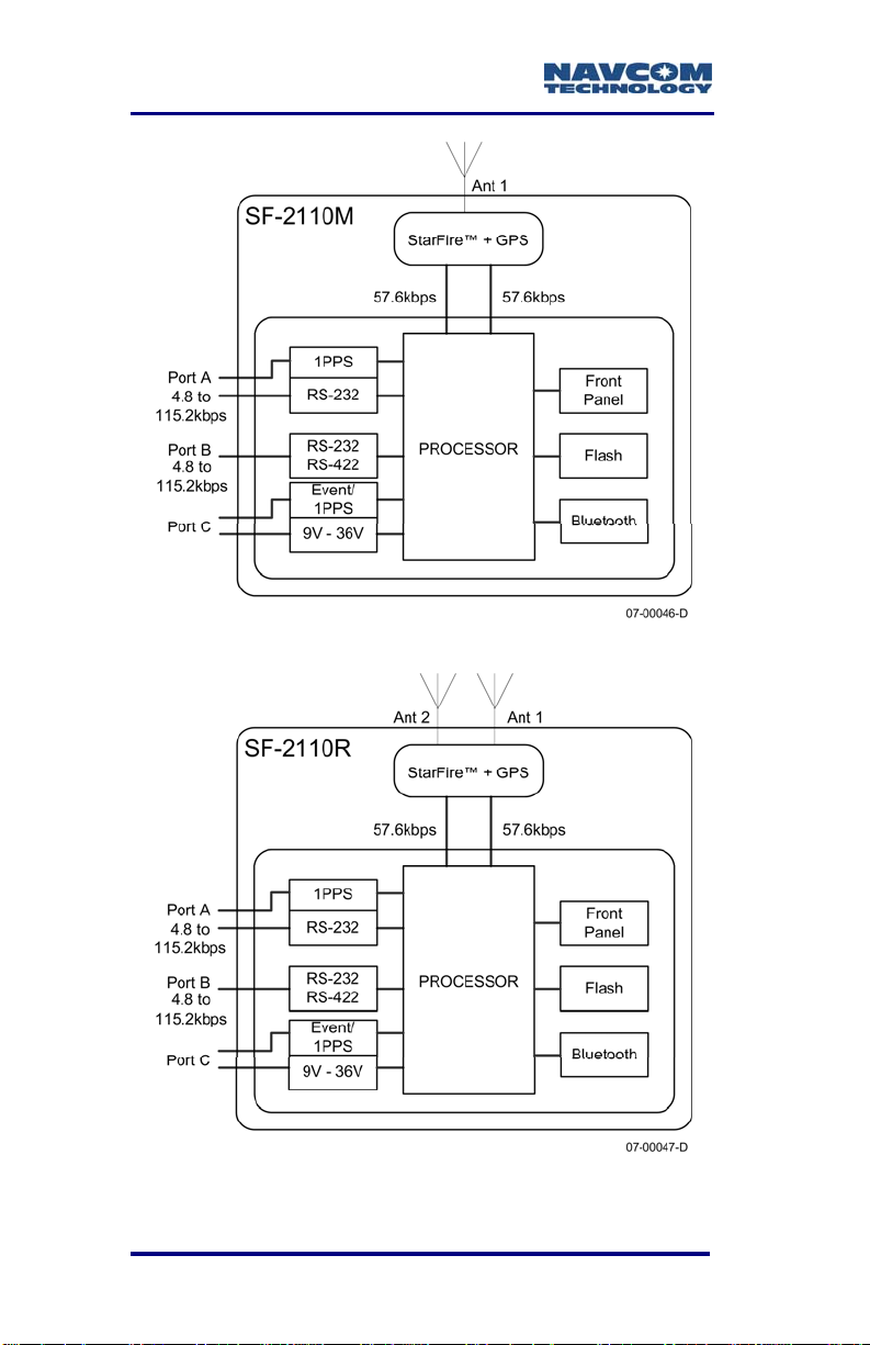
Block Diagrams
The SF-2110 has three user configurable physical
communications ports (two external and one internal)
and several logical communications ports. New
SF-2110 models include a Bluetooth module which
provides wireless communication with a Bluetooth
enabled controller. To aid in distinguishing these
ports, please refer to the block diagrams below.
(Continued)
* Consult Release Notes on the NavCom web site for availability. 3-45
Page 48
SF-2110 User Guide – Rev. C
*
*
*
Figure 16: SF-2110M Block Diagram
*
*
*
Figure 17: SF-2110R Block Diagram
3-46 * Consult Release Notes on the NavCom web site for availability.
Page 49

SF-2110 User Guide – Rev. C
Communication Port Connectivity
There is no default control port on the receiver.
Establish communications via Bluetooth or a data
cable:
9 Setup Bluetooth communications via either
StarUtil-2110 or a third party software/utility.
9 Connect the supplied Positronic 9-Pin connector
of the serial cable (P/N 94-310260-3006LF) to
Port A or Port B of the SF-2110. Connect the DB9
end to the control device.
Figure 18 shows a common configuration with
the control device connected to Port A and an
auxiliary device connected to Port B for data
logging.
Some devices may require an additional
adapter. The receiver is configured as a DCE
device.
Figure 18: Communication Port Connections
* Consult Release Notes on the NavCom web site for availability. 3-47
Page 50

SF-2110 User Guide – Rev. C
GPS Antenna Connector
The connector used on the SF-2110 is a TNC female,
labeled ANT 1 on the rear panel of the sensor as
shown in Figure 9.
Both the GPS antenna port (ANT 1)
and the StarFire antenna port
(ANT 2 - SF-2110R only) provide
5.0VDC, 150mA. Do not disconnect
the antenna when the GPS unit is
powered on.
The system is supplied with 12ft (3.6m) of RG58/U
cable (P/N 94-310261-3012LF). The cable is fitted
with two straight male TNC connectors.
The cable length between the antenna and SF-2110
should not exceed 7dB loss at 1.575GHz for optimum
performance, though the system may tolerate up to
10dB of cable loss with minimal performance. Lower
elevation satellite tracking suffers the most with more
than 7dB insertion loss.
3-48 * Consult Release Notes on the NavCom web site for availability.
Page 51

SF-2110 User Guide – Rev. C
Table 9: Acceptable Cable Lengths
Cable
Type
RG-58C 19.605 36.00 7.06 64.32 11.00 7.08
RG-142 16.494 43.00 7.09 54.12 13.00 7.04
RG-213 9.564 74.00 7.08 31.38 22.50 7.06
RG-223 17.224 41.00 7.06 56.51 12.50 7.06
LMR600 3.407 207.00 7.05 11.18 63.00 7.04
LMR400 5.262 133.00 7.00 17.26 41.00 7.08
LMR240 10.127 70.00 7.09 33.23 21.00 6.98
LMR195 14.902 47.00 7.00 48.89 14.00 6.85
Atten.
(dB) per
100 Ft.
Cable
Length
in Feet
Loss
in dB
Atten.
(dB)
per
100 m
Cable
Length
in
Meters
Loss
in dB
In-line amplifiers suitable for all GPS frequencies may
be used to increase the length of the antenna cable,
but care should be exercised that tracking
performance is not degraded due to multiple
connections, noise from the amplifier, and possible
ingress of moisture and dust to the in-line amplifier.
In-line amplifier or splitter devices must pass DC
power from the receiver to the antenna, or source the
appropriate voltage and current to the antenna (see
Antenna Specifications). In-line amplifiers may also
over-saturate the receiver front-end if improperly
used.
The antenna cable can degrade signal
quality if incorrectly installed, or the cable
loss exceeds NavCom specifications.
Take care not to kink, stretch, distort, or
damage the antenna cable. Do not place
the cable adjacent to cables carrying
electrical power or radio frequencies. In
these instances, attempt to cross cables
at 90º angles in an effort to reduce crosscoupling of RF signals.
* Consult Release Notes on the NavCom web site for availability. 3-49
Page 52

SF-2110 User Guide – Rev. C
Where the GPS antenna is exposed to
sources of electromagnetic discharge
such as lightning, install a properly
grounded in-line electrical surge
suppressor between the GPS sensor and
antenna. Install protective devices in
compliance with local regulatory codes
and practices. Protective devices must
pass DC power from the receiver to the
antenna.
3-50 * Consult Release Notes on the NavCom web site for availability.
Page 53

SF-2110 User Guide – Rev. C
Chapter 4 ...............................Configuration
The SF-2110 has a rich interface and detailed control
language, allowing each unit to be individually tailored
to a specific application.
There are essentially 3 methods available to
configure and control the SF-2110:
9 StarUtil-2110 – This program is a NavCom
developed utility designed to configure and view
many (but not all) of the SF-2110 functions. In
addition to its setup capabilities, StarUtil can
capture and log data, upload new software and
licenses to the internal processors, and query and
display various receiver performance functions.
Though it is developed as an Engineering tool, it
has its own place in the commercial market as
well. The program is provided on the CD with the
SF-2110.
9 3rd party controller – Some manufacturers have
already integrated NavCom’s control features in
their bundled hardware and software solution kits
in a variety of applications including GIS, Machine
Control, Aerial Photogrammetry, Land &
Oceanographic Survey, Agriculture, and Military
products. Information on these applications is
available from the NavCom website and customer
service.
9 User Program – Users may develop unique
operating programs to control the SF-2110
(potentially in conjunction with other devices or
utilities). To facilitate this effort, NavCom has an
additional tool available: the SF-2110 Technical
Reference Manual (TRM). The TRM is provided
on the CD with the SF-2110. Information on this
tool is also available on the NavCom website and
customer service.
* Consult Release Notes on the NavCom web site for availability. 4-51
Page 54

SF-2110 User Guide – Rev. C
Ports A and B, and Bluetooth Virtual COM Port
There is no default control port on the receiver. When
either port is connected to control software (such as
StarUtil-2110), that port becomes the control port.
PORT A
9 Configuration – Control or Data Port
9 Rate – 57.6kbps
This port is normally used to input and output
proprietary messages used for navigation and
receiver setup. Table 10 describes the default
messages needed to best initiate surveying with
minimal effort.
The user has full control over the utilized message
types and their associated rates via either
StarUtil-2110 or a third party software/utility.
PORT B
9 Configuration – Control or Data Port
9 Rate – 57.6kbps
This port is normally used to output data to other
devices or machines that can make immediate use of
the precise positioning data available from the
SF-2110. The data port outputs NCT Binary
Messages and NMEA Messages, and when applying
external dGPS corrections, also serves as the dGPS
correction input port.
BLUETOOTH VIRTUAL COM PORT
9 Configuration – Control Port
9 Rate – 230.4kbps
The PC’s virtual COM port is used to input and output
proprietary messages used for navigation and
receiver setup. Table 10 describes the default
messages needed to best initiate surveying with
minimal effort.
4-52 * Consult Release Notes on the NavCom web site for availability.
Page 55

SF-2110 User Guide – Rev. C
The user has full control over the utilized message
types and their associated rates via either
StarUtil-2110 or a third party software/utility.
Factory Default Output Messages
NCT Binary Messages
Table 10: Factory Default NCT Binary Messages
Msg Rate Description
81 On Change Ephemeris
86 On Change Channel Status
A0 On Change Alert Message
AE 600 Seconds Identification Block
B0 On Change Raw Measurement Data
B1 On Change PVT Solution
The term “On Change” indicates that
the SF-2110 will output the specified
message only when the information in
the message changes. On occasion,
there may be an epoch without a
message block output. Refer to
StarUtil-2110 User Guide.
Message Descriptions
The following message descriptions are fully defined
in the SF-2110 Technical Reference Manual (see
Related Documents)
9 81 Packed Ephemeris:
Individual satellite tracking information including:
GPS Week number of collected ephemeris, GPS
Time of week [in seconds] of collected
* Consult Release Notes on the NavCom web site for availability. 4-53
Page 56

SF-2110 User Guide – Rev. C
ephemeris, IODC, and sub-frame 1, 2, and 3
data.
9 86 Channel Status:
Receiver channel status information containing:
the GPS week, GPS Time of Week, number of
satellites viewed/tracked, PDOP, tracked satellite
identity, satellite elevation and azimuth, C/No for
the L1 signals, and correction age for each
satellite.
9 A0 Alert Text Message:
Details message receipt and processing.
9 AE Identification Block:
Details the receiver software versions (GPS
Engine, and Processor) and digital serial
numbers.
9 B0 Raw Measurement Data:
Raw Measurement Data Block containing: the
GPS Week, GPS Time of Week, Status, Channel
Status, CA Pseudorange, and L1 Phase. This
data stream is repeated for each individual
tracked satellite.
9 B1 PVT (Position, Velocity, and Time):
Provides: GPS Week number, satellites used,
latitude, longitude, navigation mode, and DOP
information.
4-54 * Consult Release Notes on the NavCom web site for availability.
Page 57

SF-2110 User Guide – Rev. C
NMEA Messages
Table 11: Factory Default NMEA Messages
Msg Rate Description
GGA On Change GPS Fix Data
VTG On Change
Course Over Ground &
Ground Speed
Message Descriptions
9 GGA GP S Fix Data:
Time, position and fix related data.
9 VTG Course Over Ground & Ground Speed:
The actual course and speed relative to the
ground.
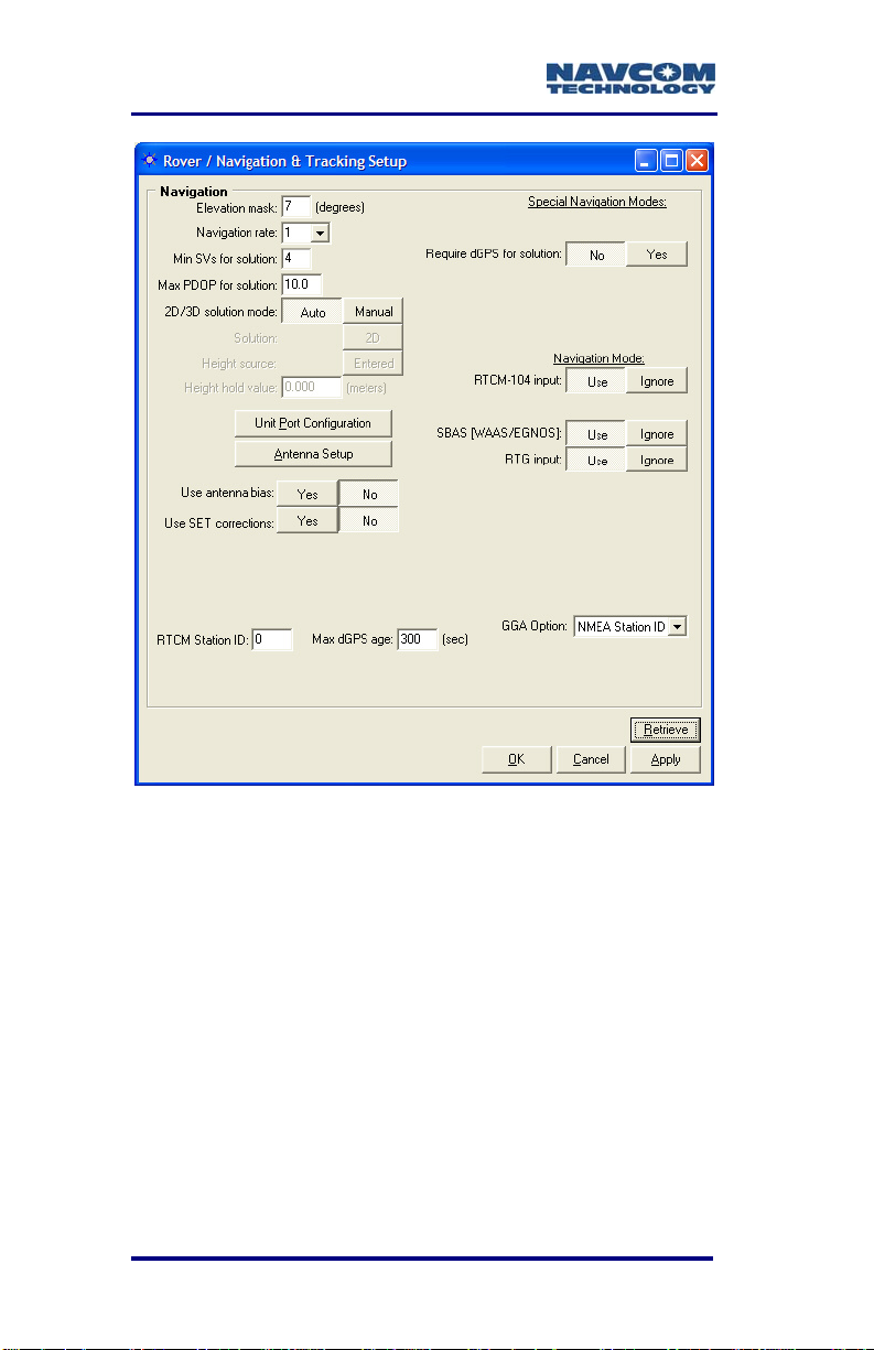
Rover Navigation Setup
NavCom’s StarUtil-2110 provides Rover setup
capabilities in the Rover / Navigation & Tracking
Setup window shown in Figure 19. Refer to the
StarUtil-2110 User Guide, included on the CD with
the SF-2110, for details.
* Consult Release Notes on the NavCom web site for availability. 4-55
Page 58
SF-2110 User Guide – Rev. C
Figure 19: StarUtil-2110 Rover Navigation Setup
3rd Party Controller Configuration Settings
Please refer to the third party controller solution
manual/user guide if the SF-2110 GPS sensor is part
of an integrated solution.
4-56 * Consult Release Notes on the NavCom web site for availability.
Page 59

SF-2110 User Guide – Rev. C
Chapter 5 .................... Safety Instructions
The SF-2110 GPS sensor is designed for precise
navigation and positioning using the Global
Positioning System. Users must be familiar with the
use of portable GPS equipment, the limitations
thereof and these safety instructions prior to use of
this equipment.
Transport
Always carry the NavCom equipment in either the
original packing material or packaging which provides
protection to the receiver and antenna against shock
and vibration.
Utilize all original packaging when transporting via
rail, ship, or air.
Maintenance
The NavCom equipment may be cleaned using a new
lint free cloth moistened with pure alcohol.
Connectors must be inspected, and if necessary
cleaned before use. Always use the provided
connector protective caps to minimize moisture and
dirt ingress.
Inspect cables regularly for kinks and cuts as these
may cause interference and equipment failure.
Damp equipment must be dried at a temperature less
than +40°C (104°F), but greater than 5°C (41°F) at
the earliest opportunity.
External Power Source
The SF-2110 is supplied with an external power cable
(P/N 94-310262-3010LF). This must be connected to
the chosen external power solution in accordance
with Chapter 2 Interfacing\Electrical Power. It is
5-57
Page 60

SF-2110 User Guide – Rev. C
important that the external power source allow
sufficient current draw for proper operation.
Insufficient supplied current will cause damage to the
external power source.
If the chosen external power source is a disposable
battery, please dispose the battery in accordance with
the local regulations.
Safety First
The owner of this equipment must ensure that all
users are properly trained prior to using the
equipment and are aware of the potential hazards
and how to avoid them.
Other manufacturer’s equipment must be used in
accordance with the safety instructions issued by that
manufacturer. This includes other manufacturer’s
equipment that may be attached to NavCom
Technology, Inc. manufactured equipment.
Always use the equipment in accordance with local
regulatory practices for safety and health at work.
There are no user serviceable parts inside the
SF-2110 GPS sensor. Accessing the inside of the
equipment will void the equipment warranty.
Take care to ensure the SF-2110 does not come into
contact with electrical power installations, the unit is
securely fastened and there is protection against
electromagnetic discharge in accordance with local
regulations.
5-58
Page 61

SF-2110 User Guide – Rev. C
A.................... GPS Module Specifications
The technical specifications of this unit are detailed
below. NavCom Technology, Inc. is constantly
improving, and updating our technology. For the
latest technical specifications for all products go to:
http://www.navcomtech.com/Support/
These GPS sensors are fitted with an internal Lithium
coin cell battery used to maintain GPS time when
power is removed from the unit. This allows faster
satellite acquisition upon unit power up. The cell has
been designed to meet over 10 years of service life
before requiring replacement at a NavCom approved
maintenance facility.
Features
9 Fully integrated receiver in robust housing
9 "All-in-view" tracking on 16 channels
(14 L1 GPS + 2 SBAS)
9 Global half-meter level accuracy using StarFire
corrections
9 Fully automatic acquisition of StarFire
broadcast
corrections
9 2 separate SBAS channels, RTCA/DO-229D
compliant (WAAS/EGNOS/MSAS/GAGAN)
9 L1 C/A code with carrier phase smoothing
9 User programmable measurement and
navigation data rates
9 Minimal data latency
9 Output format NMEA 0183 or NavCom
proprietary binary
9 Bluetooth capable in new models
* Consult Release Notes on the NavCom web site for availability. A-59
Page 62

SF-2110 User Guide – Rev. C
9 *1PPS Output
9 *Event Marker
9 Accessories Included: AC/DC adapter, Antenna,
Antenna cable, Data cable, Mounting brackets,
Documentation/Software CD
9 Software included: Command and Control Utility,
Raw binary to RINEX 2.X Conversion Utility
9 Certification: FCC Part 15 Class B, CE
9 Indicator LEDs: Power/GPS status, StarFire
status, Interface status, Bluetooth connectivity
9 Rugged and lightweight package for mobile
applications
9 User programmable output rates
9 Output of NMEA 0183 v3.1 messages
Time-To-First-Fix
Cold Start
Satellite
Acquisition
Satellite
Reacquisition
< 45 Seconds (typical/without
Almanac)
< 1 second outage time;
immediate reacquisition
< 30 seconds software, typical;
with outage time < 65 seconds
> 65 seconds outage time
requires full acquisition process
Dynamics
Acceleration: 4g
Speed: < 1000knots (515 m/s1)
Altitude: < 60,000 ft1 (18.3 km)
1
Restricted by export laws
A-60 * Consult Release Notes on the NavCom web site for availability.
Page 63

SF-2110 User Guide – Rev. C
Measurement Performance
Real-time StarFire SBAS Accuracy
Position (H):
Position (V):
Velocity:
Without WAAS IONO
<50 cm
<1 m
0.03 m/s
<1 m H; <1.5 m V
Real-time WAAS/EGNOS/MSAS/GAGAN SBAS
Accuracy
Position (H):
Position (V):
Velocity:
<1 m
<2 m
0.03 m/s
RTCM Code Differential GPS <200km (RMS)
Position (H):
Position (V):
Velocity:
<1 m
<2 m
0.03 m/s
Pseudo-range Measurement Precision (RMS)
Raw C/A code :
Raw carrier phase
noise:
90cm
5 mm
User programmable output rates
SF-2110M
PVT 1Hz Standard
5 & 10Hz Optional
Raw data 1Hz Standard
5 & 10Hz Optional
SF-2110R
PVT
1Hz Standard
5 &10Hz Optional
Raw data
1Hz Standard
5 & 10Hz Optional
* Consult Release Notes on the NavCom web site for availability. A-61
Page 64

SF-2110 User Guide – Rev. C
Data Latency
PVT < 100 ms at all rates
Raw data < 100 ms at all rates
*1PPS
Accuracy: 50ns (Relative; User
Configurable)
Connector Assignments
Port A RS-232 serial port, from 4800
bps to 115.2 kbps
*1PPS
Port B RS-232/RS-422 serial port, from
4800 bps to 115.2 kbps
Port C Power port, from 9V to 36V
*Event Marker
*1PPS
Bluetooth 1 Serial Port Service, 230.4kbps
10m (32 ft) range
A-62 * Consult Release Notes on the NavCom web site for availability.
Page 65

SF-2110 User Guide – Rev. C
Input/Output Data Messages
NCT Proprietary
Data
NMEA-0183
Messages
(Output Only)
Code Corrections RTCM 1 or 9; 3
PVT,
Raw Measurement
Satellite Messages
Nav Quality
Receiver Commands
*ALM, GGA, GLL, GSA, GST,
GSV, RMC, VTG, ZDA, GBS,
and GRS
WAAS/EGNOS/MSAS/GAGAN
StarFire
See Related Standards at the front of
this manual for information on the
various data formats
LED Display Functions (Default)
GPS
Link
Data I/O Active
Bluetooth
Satellite Based Augmentation System Signals
Position Quality
StarFire Signal Strength
Data I/O Status
Bluetooth Connectivity
RTCA/DO-229D Standard
(WAAS/EGNOS/MSAS/GAGAN)
StarFire
* Consult Release Notes on the NavCom web site for availability. A-63
Page 66

SF-2110 User Guide – Rev. C
Physical and Environmental
Size (L x W x H):
w/o Bracket
Size (L x W x H):
with Bracket
< 8.3 x 4.7 x 2.5(in)
(211 x 119.4 x 63.5)mm
< 8.3 x 6.55 x 2.56(in)
(211 x 166 x 65)mm
Weight: 1.7lbs (0.77 kg)
External Power:
Input Voltage:
Consumption:
Connectors:
I/O Ports:
DC Power:
GPS/L-Band
Antenna:
L-Band Antenna:
Antenna Power:
ANT 1:
ANT 2 (SF-2110R
9 VDC to 36 VDC
<5 W
2 x 9 pin Circular
1 x 9 pin Circular
TNC-F
TNC-F (SF-2110R Only)
5.0 VDC, 150mA
5.0 VDC, 150mA
Only):
Temperature (ambient)
Operating
Storage:
-30º to +70º C
(-22º to +158º F)
-40º to +85º C
(-40º to +185º F)
Humidity: 95% non-condensing
A-64 * Consult Release Notes on the NavCom web site for availability.
Page 67

SF-2110 User Guide – Rev. C
B........................... Antenna Specifications
Table 12: 82-001017-0001LF Standard Antenna
Frequency 1525-1660 MHz
GPS L1 plus StarFire
Polarization Right Hand Circular (RHCP)
Pre–Amplifier 35dB gain (+/-1.2dB)
Noise Figure <2.1dB
Filter Rejection 9dB @ 1690MHz
21dB @ 1626MHz
38dB @ 1660MHz
Impedance 50 Ohms
VSWR / RL
Band Rejection 20dB @ 250MHz
RF Power Handling +30dBm (1 W)
Input Voltage 2.5 – 24 VDC
Power Consumption 0.2W
Cable Connector TNC Female
Operating Temp
Altitude 70,000ft; 21,336m
Finish Skydrol resistant
Material 6061-T6 Aluminum alloy
Weight 397g (14oz)
Vibration >30g’s
≤ 2.0:1 / 9.54dB min.
39mA +
-55°C to +85°C
polyurethane Enamel with
nickel plated base
base composite radome,
impact, abrasion, UV,
solvent, skydrol resistant,
and fire retardant
10mA @ 5VDC
B-65
Page 68

SF-2110 User Guide – Rev. C
Designed to FAA TSO-C144, DO-160D,
D0-228, MIL-C-5541, MIL-E5400, MIL-I-45208A, MILSTD-810, AND SAE J1455
Figure 20: PN: 82-001017-0001LF Antenna Dimensions
To achieve the greatest level of accuracy,
the absolute phase center values must be
incorporated into the processing. Phase
B-66
Page 69

SF-2110 User Guide – Rev. C
center information on this antenna is
found in Table 12 above.
Radiation Pattern
Figure 21: 82-001017-0001LF Radiation Pattern
Optimal antenna performance is realized at
elevations greater than 30º.
There is a 10dB variation between 0º and 90º
elevation (factor 10x); therefore, lower
elevation satellites are always more difficult to
track.
There is a 5dB variation between ~35º and 0º
elevation (factor >3x)
B-67
Page 70

SF-2110 User Guide – Rev. C
Table 13: L-band SF-2110R Antenna
Part Number 82-001018-0001LF
Frequency 1525-1575 MHz
INMARSAT StarFire
Polarization Right Hand Circular (RHCP)
Pre–Amplifier 34dB gain min.
Noise Figure 2.9dB
Impedance 50 Ohms
Input Voltage 2.5 to 24 VDC
Power Consumption 0.3W typical
60mA +
10mA @ 5.0VDC
Connector TNC Female
Operating Temp
-55°C to +85°C
Finish Skydrol resistant
polyurethane Enamel base
Iriditeper MIL-C-5541
Material 6061-T6 Aluminum alloy
base composite radome,
impact, abrasion, UV,
solvent, skydrol resistant,
and fire retardant
Weight 5.2oz [146g]
Vibration >30g’s
Designed to FAA TSO-C144, DO-160D,
D0-228, MIL-C-5541, MIL-I-
45208A, MIL-STD-810, AND
SAE J1455
Wind loading 135 MPH
B-68
Page 71

SF-2110 User Guide – Rev. C
Figure 22: PN: 82-001018-0001LF Antenna
Dimensions (SF-2110R only)
B-69
Page 72

SF-2110 User Guide – Rev. C
Figure 23: PN: 82-001018-0001LF Mounts
Figure 24: Pipe Mount Adapter for L-band SF-2110R
Antenna
B-70
Page 73

Radiation Pattern
Figure 25:
82-001018-0001LF Radiation Pattern
SF-2110 User Guide – Rev. C
Optimal antenna performance is realized at
elevations between 10º and 50º.
There is an 8dB variation between 40º
and 90º elevation (factor 6.3x);
therefore, higher elevation satellites
are always more difficult to track.
There is a 3dB variation between 10º
and 0º elevation (factor >2x)
B-71
Page 74

SF-2110 User Guide – Rev. C
This page is left blank intentionally
B-72
Page 75
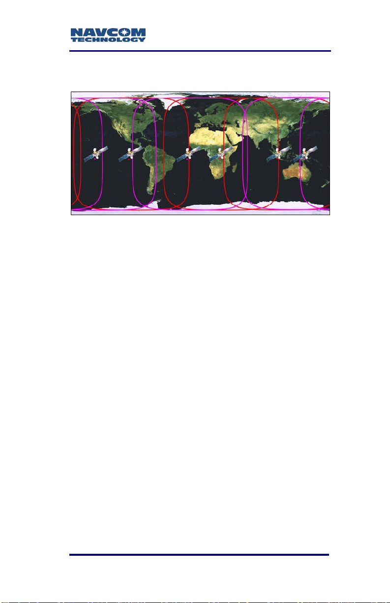
SF-2110 User Guide – Rev. C
C .................................................... StarFire
Description
The StarFire Network is a global system for the
distribution of SBAS corrections giving the user the
ability to measure their position anywhere in the world
with exceptional reliability and unprecedented
accuracy of better than 50cm (19.7 inches; in this
product). Because the SBAS corrections are
broadcast via INMARSAT geo-stationary satellites,
the user needs no local reference stations or postprocessing to get this exceptional accuracy.
Furthermore, the same accuracy is available virtually
any where on the earth's surface on land or sea from
76°N to 76°S latitude, due to the worldwide coverage
of these geo-stationary satellites.
C-73
Page 76

SF-2110 User Guide – Rev. C
Infrastructure
The system utilizes the GPS satellite system, L-Band
communication satellites, and a worldwide network of
reference stations to deliver real-time high precision
positioning.
To provide this unique service, NavCom has built a
global network of dual-frequency reference stations,
which constantly receive signals from the GPS
satellites as they orbit the earth. Data from these
reference stations is fed to two USA processing
centers in Torrance, California and Moline, Illinois
where they are processed to generate the differential
corrections.
From the two processing centers, the correction data
is fed via redundant and independent communication
links to satellite uplink stations at Laurentides,
Canada; Perth, Australia; Burum, The Netherlands;
Santa Paula, California; Auckland, New Zealand; and
Southbury, Connecticut for rebroadcast via the geostationary satellites.
The key to the accuracy and convenience of the
StarFire system is the source of SBAS corrections.
GPS satellites transmit navigation data on two
L-Band frequencies. The StarFire reference stations
are all equipped with geodetic-quality, dual-frequency
receivers. These reference receivers decode GPS
signals and send precise, high quality, dual-frequency
pseudorange and carrier phase measurements back
to the processing centers together with the data
messages, which all GPS satellites broadcast.
At the processing centers, NavCom's proprietary
differential processing techniques used to generate
real time precise orbits and clock correction data for
each satellite in the GPS constellation. This
proprietary Wide Area DGPS (WADGPS) algorithm is
C-74
Page 77

SF-2110 User Guide – Rev. C
optimized for a dual-frequency system such as
StarFire in which dual-frequency ionospheric
measurements are available at both the reference
receivers and the user receivers. It is the use of dualfrequency receivers at both the reference stations
and the user equipment together with the advanced
processing algorithms, which makes the exceptional
accuracy of the StarFire system possible.
Creating the corrections is just the first part. From our
two processing centers, the differential corrections
are then sent to the Land Earth Station (LES) for
uplink to L-Band communications satellites. The
uplink sites for the network are equipped with
NavCom-built modulation equipment, which
interfaces to the satellite system transmitter and
uplinks the correction data stream to the satellite that
broadcasts it over the coverage area. Each L-Band
satellite covers more than a third of the earth.
Users equipped with a StarFire precision GPS
receiver actually have two receivers in a single
package, a GPS receiver and an L-Band
communications receiver, both designed by NavCom
for this system. The GPS receiver tracks all the
satellites in view and makes pseudorange
measurements to the GPS satellites. Simultaneously,
the L-Band receiver receives the correction
messages broadcast via the L-Band satellite. When
the corrections are applied to the GPS
measurements, a position measurement of
unprecedented real time accuracy is produced.
Reliability
The entire system meets or exceeds a target
availability of 99.99%. To achieve this, every part of
the infrastructure has a built-in back-up system.
C-75
Page 78

SF-2110 User Guide – Rev. C
All the reference stations are built with duplicate
receivers, processors and communication interfaces,
which switch automatically or in response to a remote
control signal from the processing centers. The data
links from the reference stations use the Internet as
the primary data link and are backed up by dedicated
communications lines, but in fact the network is
sufficiently dense that the reference stations
effectively act as back up for each other. If one or
several fail, the net effect on the correction accuracy
is not impaired.
There are two continuously running processing
centers, each receiving all of the reference site inputs
and each with redundant communications links to the
uplink LES. The LESs are equipped with two
complete and continuously operating sets of uplink
equipment arbitrated by an automatic fail over switch.
Finally, a comprehensive team of support engineers
maintains round the clock monitoring and control of
the system.
The network is a fully automated self-monitoring
system. To ensure overall system integrity, an
independent integrity monitor receiver, similar to a
standard StarFire user receiver, is installed at every
reference station to monitor service quality. Data from
these integrity monitors is sent to the two
independent processing hubs in Torrance, California
and Moline, Illinois. Through these integrity monitors
the network is continuously checked for overall SBAS
positioning accuracy, L-Band signal strength, data
integrity and other essential operational parameters.
C-76
Page 79

SF-2110 User Guide – Rev. C
How to Access the StarFire Service
StarFire is a subscription service. The user pays a
subscription, which licenses the use of the service for
a predetermined period of time.
Subscriptions can be purchased for quarterly,
biannual or annual periods and are available via a
NavCom authorized representative, or by contacting
NavCom Sales Department
An authorized subscription will provide an encrypted
key, which is specific to the Serial Number of the
NavCom receiver to be authorized. This is entered
into the receiver using the provided controller
solution. Typically the initial license is preinstalled at
the factory, and subsequent licenses will be installed
by the user.
The only piece of equipment needed to use the
StarFire system is a StarFire receiver. NavCom offers
a variety of receivers configured for different
applications. Details of all the StarFire receivers are
available from the NavCom authorized local
representative or the NavCom website at:
www.NavComtech.com
.
StarFire receivers include a dual-frequency GPS
receiver and an L-Band receiver integrated into a
single unit to provide the exceptional precise
positioning capability of the StarFire Network,
anywhere, anytime.
C-77
Page 80

SF-2110 User Guide – Rev. C
Figure 26: StarFire Network
C-78
Page 81
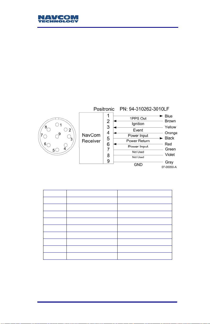
SF-2110 User Guide – Rev. C
D .....................*Event Input Configuration
Figure 27 details the wiring of the Event/Can cable
assembly NavCom part number
P/N 94-310262-3010LF.
Refer to Chapter 2, Event section for detailed
electrical specifications.
Table 14 details the wiring configuration required for
Event-Hi, and Event-Lo pulse sensing.
Figure 27: *Event Cable Wiring Diagram
Table 14: *Event Wiring Connections
Pin # Signal Name Color
1 *1PPS Out Blue
2 Ignition Brown
3 *Event Yellow
4 Power Input Orange
5 Power Return Black
6 Power Input Red
7 Not Used Green
8 Not Used Violet
9 GND Gray
Once the cable is wired to correspond with the event
pulse requirements, configure the receiver to output
the message containing a time mark, referenced to
* Consult Release Notes on the NavCom web site for availability. D-79
Page 82

SF-2110 User Guide – Rev. C
the time kept within the receiver, indicating when the
event is sensed (0xB4).
The *Event Input can be triggered on the Rising or
Falling edge of the input pulse. Configuration is
possible thru the StarUtil-2110 program.
Figure 28 is a screen capture of the program’s PPS &
Event Latch window.
Figure 28: *PPS & Event Latch Configuration
Enable the Event Latch message (0xB4) in the NCT
Binary Messages output list. Set the Message Rate
for 0xB4 to “On Trigger”. Right-Click on the Rate cell
for the B4 Message, and follow the menu as depicted
in Figure 29. Once configured, the Event Latch
Message (0xB4) is output upon recognition of an
input trigger by the receiver.
Figure 29: *Event Latch Output Rate Configuration
D-80 * Consult Release Notes on the NavCom web site for availability.
Page 83

SF-2110 User Guide – Rev. C
E................. CE Declaration of Conformity
E-81
Page 84

SF-2110 User Guide – Rev. C
This page is left blank intentionally
E-82
Page 85

SF-2110 User Guide – Rev. C
Glossary
.yym files see meteorological files (where yy = two
digit year data was collected).
.yyn files see navigation files (where yy = two digit
year data was collected).
.yyo files see observation files (where yy = two digit
year data was collected).
almanac files an almanac file contains orbit
information, clock corrections, and atmospheric delay
parameters for all satellites tracked. It is transmitted
to a receiver from a satellite and is used by mission
planning software.
alt see altitude.
altitude vertical distance above the ellipsoid or geoid.
It is always stored as height above ellipsoid in the
GPS receiver but can be displayed as height above
ellipsoid (HAE) or height above mean sea level
(MSL).
Antenna Phase Center (APC) The point in an
antenna where the GPS signal from the satellites is
received. The height above ground of the APC must
be measured accurately to ensure accurate GPS
readings. The APC height can be calculated by
adding the height to an easily measured point, such
as the base of the antenna mount, to the known
distance between this point and the APC.
APC see antenna phase center or phase center.
Autonomous positioning (GPS) a mode of
operation in which a GPS receiver computes position
fixes in real time from satellite data alone, without
reference to data supplied by a reference station or
orbital clock corrections. Autonomous positioning is
typically the least precise positioning procedure a
Glossary-83
Page 86

SF-2110 User Guide – Rev. C
GPS receiver can perform, yielding position fixes that
are precise to 100 meters with Selective Availability
on, and 30 meters with S/A off.
azimuth the azimuth of a line is its direction as given
by the angle between the meridian and the line
measured in a clockwise direction from the north
branch of the meridian.
base station see reference station.
baud rate (bits per second) the number of bits sent
or received each second. For example, a baud rate of
9600 means there is a data flow of 9600 bits each
second. One character roughly equals 10 bits.
bits per second see baud rate.
bps see baud rate.
BSW (British Standard Whitworth) a type of coarse
screw thread. A 5/8” diameter BSW is the standard
mount for survey instruments.
C/A code see Coarse Acquisition code.
CAN BUS a balanced (differential) 2-wire interface
that uses an asynchronous transmission scheme.
Often used for communications in vehicular
applications.
channel a channel of a GPS receiver consists of the
circuitry necessary to receive the signal for a single
GPS satellite.
civilian code see Coarse Acquisition code.
Coarse Acquisition code (C/A or Civilian code)
the pseudo-random code generated by GPS
satellites. It is intended for civilian use and the
accuracy of readings using this code can be
degraded if selective availability (S/A) is introduced
by the US Department of Defense.
Glossary-84
Page 87

SF-2110 User Guide – Rev. C
COM# shortened form of the word Communications.
Indicates a data communications port to/from the
GPS sensor to a controller or data collection device.
Compact Measurement Record (CMR) a standard
format for DGPS corrections used to transmit
corrections from a reference station to rover sensors.
See Related Standards in Notices.
controller a device consisting of hardware and
software used to communicate and manipulate the
I/O functions of the GPS sensor.
convergence period (StarFire) is the time necessary
for the received StarFire signal corrections to be
applied and the position filtered to optimal
performance. The convergence period is typically 30
to 45 minutes to achieve <decimeter accuracy. This
period may be overcome using the Quick Start
method.
data files files that contain Proprietary, GPS, NMEA,
RTCM, or any type of data logged from a GPS
receiver.
datum A reference datum is a known and constant
surface which can be used to describe the location of
unknown points. Geodetic datums define the size and
shape of the earth and the origin and orientation of
the coordinate systems used to map the earth.
DB9P a type of electrical connector containing 9
contacts. The P indicates a plug pin (male).
DB9S a type of electrical connector containing 9
contacts. The S indicates a slot pin (female).
DCE Data Communications Equipment. Defined pin
assignments based on the IEEE RS-232 signaling
standard. See Figure 30.
Glossary-85
Page 88

SF-2110 User Guide – Rev. C
`
Modem
DTE
DB25RJ45 DB9DB9 DB25
6
5
4
2
3
1
8
20
1
8
2
3
3
2
4
5
7
6
6
7
4
8
5
Straight-Through Cable
DCD
RD
TD
DTR
GND
DSR
RTS
CTS
DCE
1
2
3
4
5
6
7
8
07-00041-A
8
3
2
20
7
6
4
5
Figure 30: DTE to DCE RS-232 Pin Assignments
DGPS see Differential GPS.
Differential GPS (DGPS) a positioning procedure
that uses two receivers, a rover at an unknown
location and a reference station at a known, fixed
location. The reference station computes corrections
based on the actual and observed ranges to the
satellites being tracked. The coordinates of the
unknown location can be computed with sub-meter
level precision by applying these corrections to the
satellite data received by the rover.
Dilution of Precision (DOP) a class of measures of
the magnitude of error in GPS position fixes due to
the orientation of the GPS satellites with respect to
the GPS receiver. There are several DOPs to
measure different components of the error. Note: this
is a unitless value. see also PDOP.
DOP see Dilution of Precision.
DTE Data Terminal Equipment. See DCE.
Glossary-86
Page 89

SF-2110 User Guide – Rev. C
dual-frequency a type of GPS receiver that uses
both L1 and L2 signals from GPS satellites. A dualfrequency receiver can compute more precise
position fixes over longer distances and under more
adverse conditions because it compensates for
ionospheric delays.
dynamic mode when a GPS receiver operates in
dynamic mode, it assumes that it is in motion and
certain algorithms for GPS position fixing are enabled
in order to calculate a tighter position fix.
EGNOS (European Geostationary Navigation
Overlay Service) a European satellite system used
to augment the two military satellite navigation
systems now operating, the US GPS and Russian
GLONASS systems.
elevation distance above or below Local Vertical
Datum.
elevation mask the lowest elevation, in degrees, at
which a receiver can track a satellite. Measured from
the horizon to zenith, 0º to 90º.
ellipsoid a mathematical figure approximating the
earth’s surface, generated by rotating an ellipse on its
minor axis. GPS positions are computed relative to
the WGS-84 ellipsoid. An ellipsoid has a smooth
surface, which does not match the earth’s geoidal
surface closely, so GPS altitude measurements can
contain a large vertical error component.
Conventionally surveyed positions usually reference a
geoid, which has an undulating surface and
approximates the earth’s surface more closely to
minimize altitude errors.
epoch literally a period of time. This period of time is
defined by the length of the said period.
Glossary-87
Page 90

SF-2110 User Guide – Rev. C
GAGAN (GPS Aided Geo Augmented Navigation)
an Indian satellite system that provides a set of
corrections for the GPS satellites, which are valid for
the Indian region. They incorporate satellite orbit and
clock corrections.
geoid the gravity-equipotential surface that best
approximates mean sea level over the entire surface
of the earth. The surface of a geoid is too irregular to
use for GPS readings, which are measured relative to
an ellipsoid. Conventionally surveyed positions
reference a geoid. More accurate GPS readings can
be obtained by calculating the distance between the
geoid and ellipsoid at each position and subtracting
this from the GPS altitude measurement.
GIS (Geographical Information Systems) a
computer system capable of assembling, storing,
manipulating, updating, analyzing and displaying
geographically referenced information, i.e. data
identified according to their locations. GIS technology
can be used for scientific investigations, resource
management, and development planning. GIS
software is used to display, edit, query and analyze
all the graphical objects and their associated
information.
Global Positioning System (GPS) geometrically,
there can only be one point in space, which is the
correct distance from each of four known points. GPS
measures the distance from a point to at least four
satellites from a constellation of 24 NAVSTAR
satellites orbiting the earth at a very high altitude.
These distances are used to calculate the point’s
position.
GMT see Greenwich Mean Time.
GPS see Global Positioning System.
GPS time a measure of time. GPS time is based on
UTC, but does not add periodic ‘leap seconds’ to
Glossary-88
Page 91

SF-2110 User Guide – Rev. C
correct for changes in the earth’s period of rotation.
As of September 2002 GPS time is 13 seconds
ahead of UTC.
Greenwich Mean Time (GMT) the local time of the
0° meridian passing through Greenwich, England.
HAE see altitude, and ellipsoid.
IODC Issue of Data, Clock - The IODC indicates the
issue number of the data set and thereby provides
the user with a convenient means of detecting any
change in the correction parameters. The transmitted
IODC will be different from any value transmitted by
the satellite during the preceding seven days.
JPL Jet Propulsion Laboratory.
Kbps kilobits per second.
L-Band the group of radio frequencies extending
from approximately 400MHz to approximately
1600MHz. The GPS carrier frequencies L1
(1575.4MHz) and L2 (1227.6 MHz) are in the L-Band
range.
L1 carrier frequency the primary L-Band carrier
used by GPS satellites to transmit satellite data. The
frequency is 1575.42MHz. It is modulated by C/A
code, P-code, or Y-code, and a 50 bit/second
navigation message. The bandwidth of this signal is
1.023MHz.
L2 carrier frequency the secondary L-Band carrier
used by GPS satellites to transmit satellite data. The
frequency is 1227.6MHz. It is modulated by P-code,
or Y-code, and a 50 bit/second navigation message.
The bandwidth of this signal is 10.23MHz.
lat see latitude.
latitude (lat) the north/south component of the
coordinate of a point on the surface on the earth;
expressed in angular measurement from the plane of
Glossary-89
Page 92

SF-2110 User Guide – Rev. C
the equator to a line from the center of the earth to
the point of interest. Often abbreviated as Lat.
LED acronym for Light Emitting Diode.
LEMO a type of data or power connector.
LES Land Earth Station the point on the earth’s
surface where data is up linked to a satellite.
logging interval the frequency at which positions
generated by the receiver are logged to data files.
lon see longitude.
longitude (long) the east/west component of the
coordinate of a point on the surface of the earth;
expressed as an angular measurement from the
plane that passes through the earth’s axis of rotation
and the 0° meridian and the plane that passes
through the axis of rotation and the point of interest.
Often abbreviated as Long.
Mean Sea Level (MSL) a vertical surface that
represents sea level.
meridian one of the lines joining the north and south
poles at right angles to the equator, designated by
degrees of longitude, from 0° at Greenwich to 180°.
meteorological (.YYm) files one of the three file
types that make up the RINEX file format. Where YY
indicates the last two digits of the year the data was
collected. A meteorological file contains atmospheric
information.
MSAS (MTSAT Satellite-based Augmentation
System) a Japanese satellite system that provides a
set of corrections for the GPS satellites, which are
valid for the Japanese region. They incorporate
satellite orbit and clock corrections.
MSL see Mean Sea Level.
Glossary-90
Page 93

SF-2110 User Guide – Rev. C
multipath error a positioning error resulting from
interference between radio waves that has traveled
between the transmitter and the receiver by two paths
of different electrical lengths.
navigation (.YYn) files one of the three file types
that make up the RINEX file format. Where YY
indicates the last two digits of the year the data was
collected. A navigation file contains satellite position
and time information.
observation (.YYo) files one of the three file types
that make up the RINEX file format. Where YY
indicates the last two digits of the year the data was
collected. An observation file contains raw GPS
position information.
P/N Part Number.
P-code the extremely long pseudo-random code
generated by a GPS satellite. It is intended for use
only by the U.S. military, so it can be encrypted to Ycode deny unauthorized users access.
parity a method of detecting communication errors by
adding an extra parity bit to a group of bits. The parity
bit can be a 0 or 1 value so that every byte will add up
to an odd or even number (depending on whether
odd or even parity is chosen).
PDA Personal Digital Assistant.
PDOP see Position Dilution of Precision.
PDOP mask the highest PDOP value at which a
receiver computes positions.
phase center the point in an antenna where the
GPS signal from the satellites is received. The height
above ground of the phase center must be measured
accurately to ensure accurate GPS readings. The
phase center height can be calculated by adding the
height to an easily measured point, such as the base
Glossary-91
Page 94

SF-2110 User Guide – Rev. C
of the antenna mount, to the known distance between
this point and the phase center.
Position the latitude, longitude, and altitude of a
point. An estimate of error is often associated with a
position.
Position Dilution of Precision (PDOP) a measure of
the magnitude of Dilution of Position (DOP) errors in
the x, y, and z coordinates.
Post-processing a method of differential data
correction, which compares data logged from a
known reference point to data logged by a roving
receiver over the same period of time. Variations in
the position reported by the reference station can be
used to correct the positions logged by the roving
receiver. Post-processing is performed after the user
collects the data and returns to the office, rather than
in real time as data is logged, so it can use complex,
calculations to achieve greater accuracy.
Precise code see P-code.
PRN (Uppercase) typically indicates a GPS satellite
number sequence from 1 – 32.
prn (Lower Case) see Pseudorandom Noise.
Protected code see P-code.
Proprietary commands those messages sent to and
received from GPS equipment produced by NavCom
Technology, Inc. own copyrighted binary language.
pseudo-random noise (prn) a sequence of data that
appears to be randomly distributed but can be exactly
reproduced. Each GPS satellite transmits a unique
PRN in its signals. GPS receivers use PRNs to
identify and lock onto satellites and to compute their
pseudoranges.
Pseudorange the apparent distance from the
reference station’s antenna to a satellite, calculated
Glossary-92
Page 95

SF-2110 User Guide – Rev. C
by multiplying the time the signal takes to reach the
antenna by the speed of light (radio waves travel at
the speed of light). The actual distance, or range, is
not exactly the same because various factors cause
errors in the measurement.
PVT GPS information depicting Position, Velocity,
Time in the NCT proprietary message format.
Quick Start (StarFire) a startup mode that allows
instant <decimeter accuracy with received StarFire
signals, allowing the convergence period to be
waived. The Quick Start (user input) position should
have an accuracy of better <decimeter to achieve
maximum results. Any error in the user input position
will bias the StarFire position error accordingly, until
convergence can correct the bias. In this scenario,
convergence may take longer than the typical startup
convergence period.
Radio Technical Commission for Maritime
Services see RTCM.
range the distance between a satellite and a GPS
receiver’s antenna. The range is approximately equal
to the pseudorange. However, errors can be
introduced by atmospheric conditions which slow
down the radio waves, clock errors, irregularities in
the satellite’s orbit, and other factors. A GPS
receiver’s location can be determined if you know the
ranges from the receiver to at least four GPS
satellites. Geometrically, there can only be one point
in space, which is the correct distance from each of
four known points.
RCP a NavCom Technology, Inc. proprietary
processing technique in which carrier phase
measurements, free of Ionospheric and Troposphere
effects are used for navigation.
Real-Time Kinematic (RTK) a GPS system that
yields very accurate 3D position fixes immediately in
Glossary-93
Page 96

SF-2110 User Guide – Rev. C
real-time. The base station transmits its GPS position
to roving receivers as the receiver generates them,
and the roving receivers use the base station
readings to differentially correct their own positions.
Accuracies of a few centimeters in all three
dimensions are possible. RTK requires dual
frequency GPS receivers and high speed radio
modems.
reference station a reference station collects GPS
data for a fixed, known location. Some of the errors in
the GPS positions for this location can be applied to
positions recorded at the same time by roving
receivers which are relatively close to the reference
station. A reference station is used to improve the
quality and accuracy of GPS data collected by roving
receivers.
RHCP Right Hand Circular Polarization used to
discriminate satellite signals. GPS signals are RHCP.
RINEX (Receiver Independent Exchange) is a file
set of standard definitions and formats designed to be
receiver or software manufacturer independent and to
promote the free exchange of GPS data. The RINEX
file format consists of separate files, the three most
commonly used are:
the observation (.YYo) file,
the navigation (.YYn) file,
meteorological (.YYm) files; where YY indicates
the last two digits of the year the data was
collected.
rover any mobile GPS receiver and field computer
collecting data in the field. A roving receiver’s position
can be differentially corrected relative to a stationary
reference GPS receiver or by using GPS orbit and
clock corrections from a SBAS such as StarFire.
roving receiver see rover.
Glossary-94
Page 97

SF-2110 User Guide – Rev. C
RTCM (Radio Technical Commission for Maritime
Services) a standard format for Differential GPS
corrections used to transmit corrections from a base
station to rovers. RTCM allows both real-time
kinematic (RTK) data collection and post-processed
differential data collection. RTCM SC-104 (RTCM
Special Committee 104) is the most commonly used
version of RTCM message.
RTK see Real-time kinematic.
RTG Real Time GIPSY, a processing technique
developed by NASA’s Jet Propulsion Laboratory to
provide a single set of real time global corrections for
the GPS satellites.
S/A see Selective Availability.
SBAS (Satellite Based Augmentation System) this
is a more general term, which encompasses WAAS,
StarFire and EGNOS type corrections.
Selective Availability (S/A) is the deliberate
degradation of the GPS signal by encrypting the Pcode and dithering the satellite clock. When the US
Department of Defense uses S/A, the signal contains
errors, which can cause positions to be inaccurate by
as much as 100 meters.
Signal-to-Noise Ratio (SNR) is a measure of a
satellite’s signal strength.
single-frequency is a type of receiver that only uses
the L1 GPS signal. There is no compensation for
ionospheric effects. The SF-2110 is a single
frequency receiver.
SNR see signal-to-noise Ratio.
StarFire a set of real-time global orbit and clock
corrections for GPS satellites. StarFire equipped
receivers are capable of real-time decimeter
positioning
Glossary-95
Page 98

SF-2110 User Guide – Rev. C
(see Appendix C).
Spread Spectrum Radio (SSR) a radio that uses
wide band, noise like (pseudo-noise) signals that are
hard to detect, intercept, jam, or demodulate making
any data transmitted secure. Because spread
spectrum signals are so wide, they can be transmitted
at much lower spectral power density (Watts per
Hertz), than narrow band signals.
SV (Space Vehicle) a GPS satellite.
Universal Time Coordinated (UTC) a time standard
maintained by the US Naval Observatory, based on
local solar mean time at the Greenwich meridian.
GPS time is based on UTC.
UTC see Universal Time Coordinated.
WAAS (Wide Area Augmentation System) a US
satellite system that provides a set of corrections for
the GPS satellites, which are valid for the North
American region. They incorporate satellite orbit and
clock corrections.
WADGPS (Wide Area Differential GPS) a set of
corrections for the GPS satellites, which are valid for
a wide geographic area.
WGS-84 (World Geodetic System 1984) the current
standard datum for global positioning and surveying.
The WGS-84 is based on the GRS-80 ellipsoid.
Y-code the name given to encrypted P-code when
the U.S. Department of Defense uses selective
availability.
Glossary-96
Page 99

SF-2110 User Guide – Rev. C
This page is left blank intentionally
Glossary-97
 Loading...