

Page 1
S
S
F--
F
2
2
0
0
4
4
0
0
GGPPSS PPrroodduucctt
UUsseerr GGuuiidde
e
NavCom Technology, Inc.
20780 Madrona Avenue
Torrance, CA 90503
USA
Tel: +1 310.381.2000
Fax: +1 310.381.2001
sales@navcomtech.com
www.navcomtech.com
Page 2

Page 3

SF-2040 User Guide - Rev. E
Table of Contents
Table of Contents................................................. i
Notices.................................................................. ii
Chapter 1 Introduction.................................... 7
System Overview..................................................... 7
Applications .......................................................... 10
Unique Features .................................................... 10
Chapter 2 Interfacing..................................... 13
Electrical Power Supply..........................................13
Communication Ports............................................16
Indicator Panel ......................................................18
Chapter 3 Installation .................................... 22
SF-2040................................................................. 22
Communications Ports .......................................... 25
GPS Sensor............................................................ 26
Chapter 4 Configuration................................ 27
Factory Default Settings.........................................27
Advanced Configuration Settings........................... 30
Chapter 5 Safety Instructions ........................ 31
FCC Notice............................................................ 31
Transport .............................................................. 31
Maintenance ......................................................... 32
External Power Source ........................................... 32
Battery ..................................................................32
Safety First............................................................. 37
A
GPS
Sensor Technical Specifications ......... 38
SF-2040................................................................. 38
B StarFire ..................................................... 43
Description............................................................ 43
How to Access the
Glossary............................................................. 49
StarFire
Service...................... 47
i
Page 4

SF-2040 User Guide - Rev. E
Notices
SF-2040
P/N
Revision E August 2005
Serial Number:
Date Delivered:
GPS
Products User Guide
96-310003-3001
Copyright
2002 by NavCom Technology, Inc.
All rights reserved. No part of this work or the computer
programs described herein may be reproduced or
stored or transmitted by any means, without the
written permission of the copyright holders. Translation
in any language is prohibited without the permission of
the copyright holders.
Trademarks
The ‘find your way’, ‘NavCom Globe’ and NAVCOM
TECHNOLOGY logos are trademarks of NavCom
Technology, Inc.
Deere & Company. All other product and brand names
are trademarks or registered trademarks of their
respective holders.
StarFire
is a registered trademark of
FCC Notice
This device complies with Part 15 of the FCC Rules.
Operation is subject to the following two conditions:
ii
Page 5

SF-2040 User Guide - Rev. E
(1) this device may not cause harmful interference, and
(2) this device must accept any interference received,
including interference that may cause undesired
operation.
User Notice
NAVCOM TECHNOLOGY, INC. SHALL NOT BE
RESPONSIBLE FOR ANY INACCURACIES, ERRORS, OR
OMISSIONS IN INFORMATION CONTAINED HEREIN,
INCLUDING, BUT NOT LIMITED TO, INFORMATION
OBTAINED FROM THIRD PARTY SOURCES, SUCH AS
PUBLICATIONS OF OTHER COMPANIES, THE PRESS, OR
COMPETITIVE DATA ORGANIZATIONS.
THIS PUBLICATION IS MADE AVAILABLE ON AN “AS IS”
BASIS AND NAVCOM TECHNOLOGY, INC.
SPECIFICALLY DISCLAIMS ALL ASSOCIATED
WARRANTIES, WHETHER EXPRESS OR IMPLIED. IN NO
EVENT WILL NAVCOM TECHNOLOGY, INC. BE LIABLE
FOR DIRECT, INDIRECT, SPECIAL, INCIDENTAL, OR
CONSEQUENTIAL DAMAGES IN CONNECTION WITH
THE USE OF OR RELIANCE ON THE MATERIAL
CONTAINED IN THIS PUBLICATION, EVEN IF ADVISED
OF THE POSSIBILITY OF SUCH DAMAGES. NAVCOM
TECHNOLOGY, INC. RESERVES THE RIGHT TO MAKE
IMPROVEMENTS OR CHANGES TO THIS PUBLICATION
AND THE PRODUCTS AND SERVICES HEREIN
DESCRIBED AT ANY TIME, WITHOUT NOTICE OR
OBLIGATION.
Limited Warranty
NavCom Technology, Inc., warrants that its products
will be free from defects in workmanship at the time of
delivery. Under this limited warranty parts found to be
defective or defects in workmanship will be repaired or
replaced at the discretion of NavCom Technology, Inc.,
iii
Page 6

SF-2040 User Guide - Rev. E
at no cost to the Buyer, provided that the Buyer returns
the defective product to NavCom Technology, Inc. in
the original supplied packaging and pays all
transportation charges, duties, and taxes associated
with the return of the product. Parts replaced during
the warranty period do not extend the period of the
basic limited warranty.
This provision does not extend to any NavCom
Technology, Inc. products, which have been subjected
to misuse, accident or improper installation,
maintenance or application, nor does it extend to
products repaired or altered outside the NavCom
Technology, Inc. production facility unless authorized in
writing by NavCom Technology, Inc.
THIS PROVISION IS EXPRESSLY ACCEPTED BY THE
BUYER IN LIEU OF ANY OR ALL OTHER AGREEMENTS,
STATEMENTS OR REPRESENTATIONS, EXPRESSED OR
IMPLIED, IN FACT OR IN LAW, INCLUDING THE
IMPLIED WARRANTIES OF MERCHANTABILITY AND
FITNESS FOR A PARTICULAR PURPOSE AND OF ALL
DUTIES OR LIABILITIES OF NAVCOM TECHNOLOGY,
INC. TO THE BUYER ARISING OUT OF THE USE OF THE
GOODS, AND NO AGREEMENT OR UNDERSTANDING
VARYING OR EXTENDING THE SAME WILL BE BINDING
UPON NAVCOM TECHNOLOGY, INC. UNLESS IN
WRITING, SIGNED BY A DULY-AUTHORIZED OFFICER
OF NAVCOM TECHNOLOGY, INC.
This limited warranty period is one (1) year from date of
purchase.
iv
Page 7

SF-2040 User Guide - Rev. E
USG FAR
Technical Data Declaration (Jan 1997)
The Contractor, NavCom Technology, Inc., hereby
declares that, to the best of its knowledge and belief,
the technical data delivered herewith under
Government contract (and subcontracts, if appropriate)
are complete, accurate, and comply with the
requirements of the contract concerning such technical
data.
StarFire
The
be purchased in order to access the service. Licenses are
non-transferable, and are subject to the terms of the
StarFire
on the
and conditions visit
email inquiry to
Licensing
StarFire
signal requires a subscription that must
™ Signal License agreement. For further details
StarFire
™ Signal Network, its capabilities, terms
www.navcomtech.com
or send an
sales@navcomtech.com
Global Positioning System
Selective availability (S/A
2000 at 04:05
stated that present
The US Government may at any time end or change
operation of these satellites without warning.
The U.S. Department of Commerce Limits
Requirements state that all exportable
contain performance limitations so that they cannot be
used to threaten the security of the United States.
Access to satellite measurements and navigation results
will be limited from display and recordable output
when predetermined values of velocity and
UTC
code) was disabled on 2nd May
. The United States government has
GPS
users do so at their own risk.
GPS
products
altitude
are
v
Page 8

SF-2040 User Guide - Rev. E
exceeded. These threshold values are far in excess of
the normal and expected operational parameters of the
GPS
SF-2040
Use of this Document
This User Guide is intended to be used by someone
familiar with the concepts of
equipment.
Sensor.
GPS
and satellite surveying
Note indicates additional information to make better
use of the product.
a Indicates a caution, care, and/or safety situation.
0 Warning indicates potentially harmful situations.
Items that have been
acronym that can be found in the Glossary.
NavCom Technology, Inc. is constantly improving, and
updating our manuals. For the latest revisions to this
User Guide in a digital format go to:
support.navcomtech.com
vi
ITALICIZED
indicate a term or
Page 9

SF-2040 User Guide - Rev. E
Chapter 1 Introduction
The SF-2040
to the precise positioning community who need a
cost-effective, high performance
unique receivers use the
worldwide
decimeter level
the world, anytime.
GPS
sensor delivers unmatched accuracy
StarFire
Differential GPS
position
accuracy, virtually anywhere in
GPS
sensor. These
Network, NavCom’s
system, for instant
System Overview
GPS
Sensor
The SF-2040 sensor consists of a 24-
frequency
channels for receiving
System (SBAS)
reception of NavCom’s
service, for instant decimeter-level position accuracy,
anywhere in the world, anytime. The sensor can output
proprietary raw data as fast as 50Hz (optional) and
Position Velocity Time (PVT
(optional) through two 115kbps serial ports with less
than 20ms latency. The horizontal accuracy of 10 cm or
better and the vertical accuracy of 15 cm or better are
maintained as each output is independently calculated
based on an actual
opposed to an extrapolation between 1Hz
measurements. NavCom's SF-2040 model sensors
deliver unmatched positioning accuracy to system
integrators needing a cost-effective, high performance
differential
precision
signals and an
GPS
sensor.
GPS
sensor with two additional
Satellite Based Augmentation
L-Band
StarFire
) data as fast as 25Hz
GPS
position measurement, as
channel dual
demodulator for
Network correction
The SF-2040 has a built-in
reception of NavCom’s
L-Band
StarFire
demodulator for
Network correction
1-7
Page 10

SF-2040 User Guide - Rev. E
service giving an immediate solution for the system
integrator. Additionally, the sensor simultaneously
accepts corrections for
seamless position output.
DGPS (WAAS/EGNOS)
assuring
Integrated
The all-in-one housing incorporates our compact
antenna with excellent tracking performance and a
stable phase center for
housing assembly features a standard 5/8”
for mounting directly to a surveyor’s pole, tripod, or
mast and is certified to 70,000 feet.
GPS
and L-Band Antenna
GPS
L1 and L2. The robust
BSW
Although rated to 70K feet, this antenna is not
designed for aircraft installations. Contact
sales@navcomtech.com
Controller
GPS
The SF-2040
external
serial COM ports.
This may be accomplished using an IBM compatible PC,
Tablet PC or
software program which implements the rich control
language defined for NavCom
User’s Guide of your
information.
Controller
sensor is designed for use with an
Personal Digital Assistant (PDA
for aircraft solutions.
solution connected via one of two
) and a
GPS
products. See the
Controller
Solution for further
GPS
thread
1-8
Page 11
SF-2040 User Guide - Rev. E
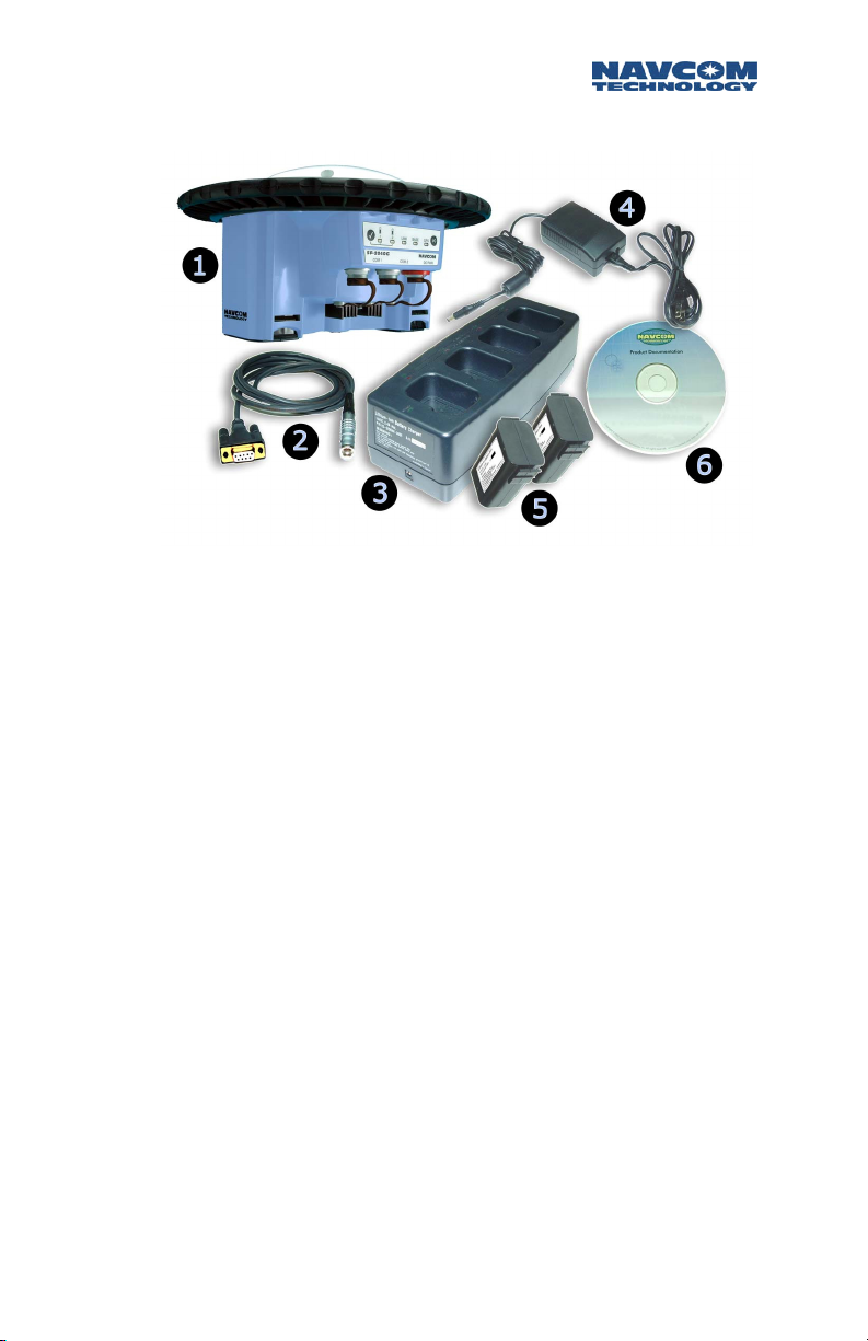
Included Items
Figure 1 SF-2040 Supplied Equipment
X SF-2040
Y
LEMO
Supplied Coily Cable P/N 94-310090-3003 (Straight
Cable P/N 94-310059-3006 shown in photo)
GPS
sensor (P/N 92-310055-3001)
7 Pin to
DB9S
Data Communications Cable
Z Battery Charger (P/N 92-310046-3001)
[ Universal AC/DC Adapter for Battery Charger
(P/N 82-020003-5001)
\ 2 Lithium Ion Batteries
P/N
(1 Battery Each =
] CD-Rom (
Guides to NavCom Technology, Inc. product line,
brochures, software utilities, and technical papers.
1-9
P/N
96-310006-3001) containing User
59-020101-0001)
Page 12

SF-2040 User Guide - Rev. E
^ SF-2040 User’s Guide {Not Shown}
(Hard Copy
P/N
96-310003-3001)
_ Ruggedized Travel Case {Not Shown}
P/N
(
Applications
79-100100-0002)
The SF-2040
number of applications including, but not limited to:
Land Survey / GIS
Asset Location
Hydrographic Survey
Topographical Survey
GPS
Sensor meets the needs of a large
Unique Features
The SF-2040
StarFire
The ability to receive NavCom’s unique
correction service is fully integrated within each unit
with no additional equipment required. A single set of
corrections can be used globally enabling a user to
achieve decimeter level positioning accuracy without
the need to deploy a separate
time and capital expenditure.
GPS
Sensor has many unique features:
[Subscription Required]
base station
StarFire
, thus saving
StarFire™ position accuracies are referenced to the
ITRF2000
1-10
datum.
Page 13

SF-2040 User Guide - Rev. E
A horizontal geodetic datum may consist of the
longitude and latitude of an initial point (origin); an
azimuth of a line (direction) to some other triangulation
station; the parameters (radius and flattening) of the
ellipsoid selected for the computations; and the geoid
separation at the origin. A change in any of these
quantities affects every point on the datum. For this
reason, while positions within a system are directly and
accurately relatable, data such as distance and azimuth
derived from computations involving geodetic positions
on different datums will be in error in proportion to the
difference in the initial quantities.
RTK Extend™
RTK Extend™ enables continuous RTK position accuracy
during radio communication outages by utilizing
NavCom’s global StarFire™ corrections. Traditionally,
when an RTK rover loses communication with the base
station, it is unable to continue to provide position
updates for more than a few seconds, resulting in user
down-time and reduced productivity. Through a
revolutionary technique called RTK Extend™, a
NavCom StarFire™ receiver, operating in RTK mode,
can transition to RTK Extend™ mode and maintain
centimeter accurate positioning during communication
loss for up to 15 minutes. RTK Extend™ allows the user
to work more efficiently and without interruption, thus
enabling them to concentrate on the work rather than
the tools.
Positioning Flexibility
The SF-2040 is capable of using two internal
Based Augmentation System
provide
Wide Area Augmentation System (WAAS)
(
SBAS
) channels that
Satellite
or
European Geostationary Navigation Overlay Service
(EGNOS)
code corrections. The SF-2040 configures
1-11
Page 14

SF-2040 User Guide - Rev. E
itself to use the most suitable correction source available
and changes as the survey dictates.
Data Sampling
GPS
L1 and L2 raw data is 1 to 5Hz in the standard
configuration and as an optional upgrade as fast as 10,
25, and 50Hz via either of the two serial ports. The
(Position, Time, & Velocity)
standard configuration and as an optional upgrade as
fast as 10 and 25Hz for high dynamic applications.
GPS
Performance
data is also 1 to 5Hz in the
PVT
The NCT-2100
incorporates several patented innovations. The receiver
provides more than 50% signal to noise ratio advantage
over competing technologies. The benefit to the user is
improved real time positioning, with independent tests
proving the NCT-2100 to be the best receiver when
facing various
Rugged Design
The rugged design of the SF-2040 system components
provides protection against the harsh environments
common to areas such as construction sites and can
withstand a 2-meter drop onto a flat hard surface.
Units have been tested to conform to MIL-STD-810F for
low pressure, solar radiation, rain, humidity, salt fog,
sand, and dust.
GPS
engine at the heart of the SF-2040
multipath
environments.
1-12
Page 15

SF-2040 User Guide - Rev. E
Chapter 2 Interfacing
This chapter details the SF-2040
and status display, appropriate sources of electrical
power, and how to interface the communication ports.
GPS
sensor connecters
Electrical Power Supply
Electrical power is input thru a 4-pin
connector located on the front panel of the SF-2040,
and labeled ‘DC PWR.’ The pin designations are shown
in Table 1; see Figure 2 for pin rotation on unit.
Pin Description
1
Return [Ground]
2
3
Power Input 10 to 30 VDC
LEMO
female
4
Table 1: External Power Cable Pin-Out
Pins 1 and 2 are connected together inside the SF-
2040
GPS
sensor. Pins 3 and 4 are connected together
inside the
GPS
sensor.
When using an external power cable longer than 5m
(15ft), it is recommended that positive voltage DC be
2-13
Page 16

SF-2040 User Guide - Rev. E
applied on both pins 3 and 4, and return on both pins
1 and 2.
The optional NavCom P/N 82-020002-5001 Universal
AC/DC 12 V 2 Amp Power Adapter can be used to
supply DC voltage wherever an AC outlet is available for
the SF-2040 GPS receiver. Another optional external
P/N
power cable, NavCom
(10ft) unterminated power cable fitted with a
plug type (Mfr.
strain relief, is suitable for supplying power to the SF-
GPS
2040
designations are labeled on this optional cable
assembly.
The
GPS
sensor is protected from reverse polarity by an
inline diode. It will operate on any DC voltage between
10 and 30 VDC, capable of supplying the required
current, typically. Power Consumption of the SF-2040 is
typically 8 Watts Maximum.
P/N
FGG.1K.304.CLAC50Z) and red
sensor. The wiring color code and pin
94-310060-3010 a 3m
LEMO
Voltages less than 10VDC will shut the unit down.
When power is restored, the ON switch will need to be
held down for more than 3 seconds.
0 Voltages in excess of 30VDC will damage the unit. It
is extremely important to ensure that the power
supply is well conditioned with surge protection.
This is especially true for vehicular electrical systems,
which can create voltage spikes far in excess of
30VDC.
The SF-2040 comes equipped with 2 removable Lithium
Ion battery packs that provide secondary power when
the primary external voltage is not available. Each of the
two battery packs is designed to last ~4 hours on a
single charge[conditions vary with use]. The smart
2-14
Page 17

SF-2040 User Guide - Rev. E
battery interface allows the batteries to be hot-swapped
on the fly. When battery 1 voltage level is sensed to be
between 7.5vdc to 8.2vdc, the sensor will automatically
switch over to battery 2 without the loss of a single
observation. A third battery (not supplied) could then
replace battery 1, and the process would reverse.
When external power is applied, it has precedence
over the batteries, but will not charge the batteries.
LED
Detailed information on the battery
s, batteries, and
battery charger can be found in Chapter 2 Interfacing,
Chapter 3 Installation, and Chapter 5 Safety.
2-15
Page 18
SF-2040 User Guide - Rev. E
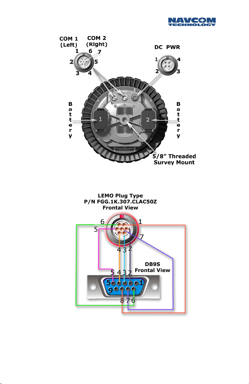
Communication Ports
The SF-2040
LEMO
connector communication ports located below
the Indicator Panel labeled
in Figure 2. Each conforms to the EIA RS232 standard
with data speeds between 1200
The pin-outs for these connectors are described in Table
2. An interface data cable (
supplied with the SF-2040 for easy startup. The cable
construction is described in Figure 3.
Pin Connections for SF-2040 Serial Cable
LEMO
Pins
1 CTS___Clear To Send 8
2 RD____Receive Data 2
3 TD____Transmit Data 3
GPS
sensor is fitted with two 7-pin female
COM
1 and
bps
P/N
94-310090-3003) is
Signal Nomenclature
DCE
w/respect to
[
DB9S
COM
2 as shown
and 115.2
DB9S
]
kbps
Pins
.
4 DTR___Data Terminal Ready 4
5 RTN___Return [Ground] 5
6 DSR___Data Set Ready 6
7 RTS___Request To Send 7
Table 2: Serial Cable Pin-Outs
2-16
Page 19
SF-2040 User Guide - Rev. E
Figure 2: SF-2040 Viewed From Bottom
Figure 3: NavCom Serial Cable 94-310090-3003
Pin 5 should connect to shield of cable at both ends.
2-17
Page 20

SF-2040 User Guide - Rev. E
Indicator Panel
Figure 4: SF-2040 Indicator Panel
The Indicator Panel provides the on/off (I/O) switch and
a quick view of the status of the SF-2040
corrections source and batteries. Each of the five
indicators has three
detailed in the following tables.
To power the unit on or off, the I/O switch must be
depressed for more than 3 seconds. During power up of
the
GPS
sensor, all
seconds.
LED
s, which depict status as
LED
s will be on for a period of 3-5
GPS
sensor,
2-18
Page 21
SF-2040 User Guide - Rev. E
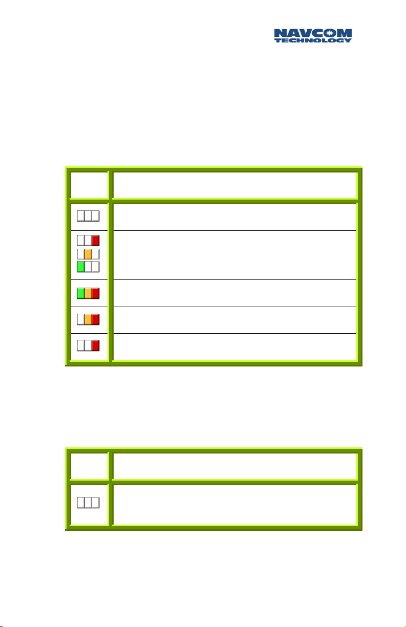
Link LEDs
The Link lights are software configurable via the
appropriate NavCom proprietary command. The link light
has numerous scenarios available so only the factory
default configuration is discussed in Table 3.
LINK Status
Indicates power is off if all other
Repeating Red to Amber to Green indicates
Searching for
Base LEDs
BASE Status
The BASE
Strong Signal Strength from
Medium Signal Strength from
Weak Signal Strength from
Table 3: Link Light Indication
standardSF-2040
StarFire
LED
s are not utilized in the
signal.
GPS
sensor configuration.
LED
StarFire
StarFire
StarFire
s are off.
.
.
.
Table 4: Link Light Indication
2-19
Page 22
SF-2040 User Guide - Rev. E
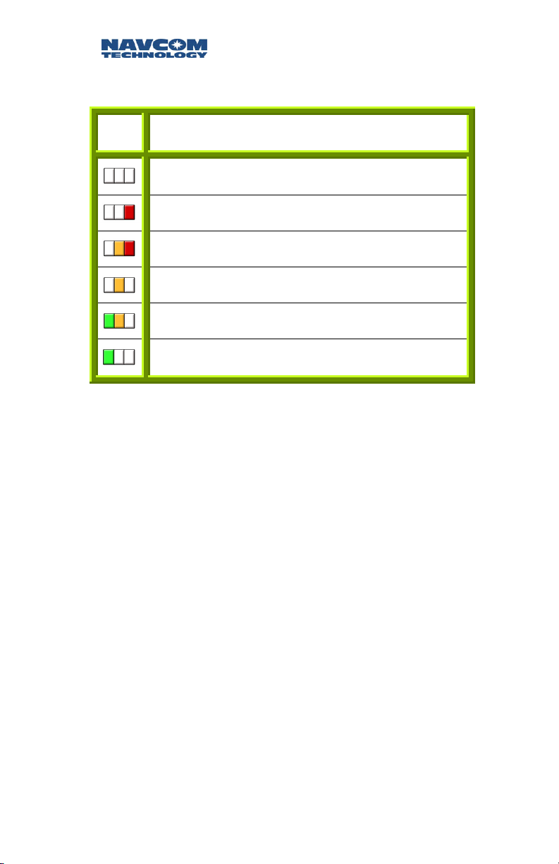
GPS
LEDs
GPS
Status
Power is off.
Power is on, No satellites tracked.
Tracking satellites,
Non-differential positioning.
Code based differential positioning.
The
(1, 2, 5, 10 and 25 Hz).
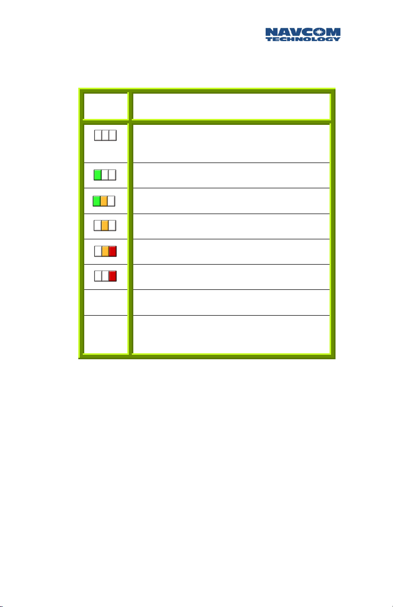
Battery LEDs
A fully charged battery indication is a GREEN light, and
an extremely low battery is indicated by a RED light.
Different combinations of the three
various battery levels. Table 6 illustrates the possible
scenarios and the estimated voltage level (as a
percentage) remaining in the battery. The battery
will blink at 5Hz for the battery in use, and 1Hz for the
battery in reserve (see Table 6 Blink Rate).
Dual frequency
Table 5:
GPS LED
s will blink at the positioning rate selected
GPS
position
Phase positioning.
Light Indication
not available yet.
LED
colors indicate
LED
s
The indicator panel has a Battery Test button, indicated
by a . Depressing this button will give an indication of
2-20
Page 23
SF-2040 User Guide - Rev. E
the battery status as per Table 6, typically for duration
of 20 to 30 seconds.
Battery Status
Battery Not Installed, or
Battery Installed but drained.
Greater Than 80% Remaining
60% - 80% Remaining
40% - 60% Remaining
20% - 40% Remaining
Less Than 20% (Solid; No Blink Rate)
In Use
Not In
Use
Table 6: Battery Status
LED
(s) Blink Rate at 5Hz
LED
(s) Blink Rate at 1Hz
LED
Indicator
The Battery lights are software configurable via the
appropriate NavCom proprietary command. The
factory default
LED
states are described in Table 6.
Batteries are NOT charged in the unit! If external
power is applied, the battery LEDs will indicate the
status of the batteries and NOT the external power
source.
2-21
Page 24

SF-2040 User Guide - Rev. E
Chapter 3 Installation
This chapter provides guidance on how the hardware
should be installed for optimum performance.
SF-2040
Charging The Batteries
The batteries (
partially charged state when you receive your SF-2040.
It is recommended that you complete one full charge
cycle (approximately 10 hours) before attempting to
use the batteries. Only use the supplied battery charger
(
P/N
92-310046-3001) and Universal AC/DC adapter
P/N
82-020003-5001) to charge the batteries
(
otherwise damage to the batteries could occur.
The charger can accommodate 4 batteries and has
independent charging bays for simultaneous charging.
The battery charger has a GREEN
power is applied to the charger. Adjacent to each
battery bay, is a RED
indicates the charge state of each battery. A GREEN
light indicates the charging of the battery is complete,
and a RED light indicates the battery is in the process of
being charged.
a
Batteries should not be stored in the charger for periods
greater than 5 days
indicator
defective battery. If this occurs, place the battery in the
SF-2040 and power on for ~10-15 minutes in order to
slightly discharge the battery.
P/N
59-020101-0001) will be in a
LED
to indicate that
LED
and a GREEN
. This will cause the charging
LED
s to shut off giving a false indication of a
LED
that
3-22
Page 25

SF-2040 User Guide - Rev. E
To charge the batteries follow the procedure below:
y Connect the Universal AC/DC adapter
P/N
82-020003-5001) to the battery charger
(
assembly (
y Plug the opposite end of the Universal AC/DC
power adapter into an AC receptacle. The GREEN
POWER LED should light up.
y Insert each battery into a battery bay. The RED
LED adjacent to that bay will light.
y One full charge cycle takes ~8 to ~10 hours to
complete.
P/N
92-310046-3001).
Installing/Removing the Batteries
The batteries are Lithium Ion type, which have none of
the memory effects seen in NiCad rechargeables.
Batteries are shipped in a partially charged state.
Batteries should receive one full charge cycle before
use.
a
The batteries should be removed from the SF-2040 if
the unit will not be used for >1 week, see Chapter 5
Safety Instructions/Battery.
0 Warning: Lithium Ion Battery Pack should be used
with designated charger only! Do Not short circuit
battery contacts. Do Not store above 60 deg C (140
deg F). Do Not disassemble battery. Do Not expose
to fire, explosive hazard. DO dispose of the battery
in accordance with the manufacturer’s
specifications. (See Chapter 5 Safety Instructions).
3-23
Page 26

SF-2040 User Guide - Rev. E
Battery Installation:
The batteries are keyed so as to prevent inverse
installation. There are two locking clips on either side of
the end of the battery as shown in Figure 5. Slide the
battery into its chamber. Press each end firmly until a
“snap” or “click” sound is heard. Repeat for the other
end.
Battery Removal:
Using the thumb and the middle finger, depress the
two locking clips firmly. The battery should pop out
enough to be pulled free of the chamber.
Care should be exercised when removing the batteries.
If the battery is in an inverted state, it may fall free to
the ground when the locking clips are depressed.
Figure 5: Battery Locking Clips
Mounting the SF-2040
The SF-2040 housing is fitted with a female 5/8”
threaded mount with a depth of 16mm (0.63”). This is
the means of mounting the SF-2040 to the surveyor’s
BSW
3-24
Page 27

SF-2040 User Guide - Rev. E
pole, or any apparatus that accepts the thread size, as
seen in Figure 2.
Communications Ports
Connect the supplied
serial cable (
setup Control Port) connector of the SF-2040. Connect
the
DB9S
some devices may require an additional adaptor, as the
receiver is configured as a DCE device.
P/N
end to your controlling device. Note that
By factory default
SF-2040.
by using the appropriate NavCom
commands
NMEA messages, cannot output on the Control Port
COM 1
. NOTE: Some output data types, such as
LEMO
7-Pin end of the NavCom
94-310090-3003) to
COM 2
can be designated as the control port
is the control port for the
COM 2
proprietary
(factory
Figure 6: Communications Interface
If you desire to provide external power to the SF-2040, you
P/N
will need an optional NavCom External Power cable (
310060-3010). Construction specifications are detailed
Chapter 2 Interfacing.
94-
3-25
Page 28

SF-2040 User Guide - Rev. E
GPS Sensor
The all in one construction of the
to be mounted on a surveyor’s pole or any apparatus
via the female 5/8” thread mounting receptacle on the
bottom of the housing. (See Figure 2) The sensor
should be stored in its ruggedized storage case. It
should not be placed in a space where it may be
exposed to excessive heat, moisture, or humidity.
There should be an unobstructed view of the sky above
a 10-degree
visibility. Any obstructions above the horizon should be
mapped using a compass and clinometer and used in
satellite prediction software with a recent satellite
almanac
location. Potential sources of interference should be
avoided where possible. Example interference sources
include overhead power lines, radio transmitters and
nearby electrical equipment.
To take full advantage of the
needs to be a clear line of sight between the antenna
and the local Inmarsat satellite. Inmarsat satellites are
geo-synchronized 35,768kms above the Equator
currently at Longitudes 098West, 025East, and
109East.
elevation mask
to assess the impact on satellite visibility at that
for optimum
GPS
StarFire
sensor allows it
GPS
satellite
service, there
There are no user serviceable parts inside the SF-2040
GPS
sensor. Opening the unit will compromise the
environmental seal and will void the equipment
warranty.
3-26
Page 29

SF-2040 User Guide - Rev. E
Chapter 4 Configuration
The SF-2040
detailed control language, which allows each unit to
be tailored specifically to the required application.
GPS
product has a rich interface and
Factory Default Settings
COM1
Configuration - Data port
Rate – 19.2Kbps
Output of NMEA messages GGA & VTG
scheduled @ 1Hz rate
COM2
Configuration - Control Port
Rate – 19.2Kbps
Input/output of NavCom Proprietary messages
used for Navigation and receiver setup. Table 7
describes the default messages that provide the
user the best opportunity to initiate surveying
with minimal effort.
The user has full control over the types of messages
utilized and their associated rates by using either
NavCom Technologies StarUtil or a third party
software/Utility
4-27
Page 30

SF-2040 User Guide - Rev. E
Message Rate Description
44
81
86
A0
AE
B0
B1
On
Change
On
Change
On
Change
On
Change
600
Seconds
On
Change
On
Change
Packed
Packed
Channel
Alert Text Message
Identification Block
Raw Measurement Data
Almanac
Ephemeris
Status
PVT
Block
COM
Table 7: Factory Setup Proprietary Messages
2
The term “On Change” indicates that the SF-2040 will
output the specified message only when the
information in the message changes. Thus in some
cases, there may be an epoch without a message block
output.
44 Packed
corresponding to each satellite in the
constellation. This information includes
number of
4-28
Almanac
almanac
: This message provides data
GPS
GPS
Week
collected,
GPS
Time of week [in
Page 31

SF-2040 User Guide - Rev. E
seconds] that
reference week,
source,
4 & 5.
81 Packed
information as it relates to individual satellites
tracked, including
collected,
almanac
ephemeris
2, & 3 data.
86 Channel Status: Provides receiver
information and contains the
of Week, NCT-2100 Engine status, solution status,
number of satellites being tracked and the number
and identity of satellites used in solution,
the satellite
A0 Alert Text Message: Details if a message has
been properly received and processed.
AE Identification Block: Details the receiver software
versions.
almanac
health, pages 1-25, and subframes
Ephemeris
GPS
Time of week [in seconds] that
was collected, IODC, and Sub-frame 1,
PRN
.
was collected,
almanac
reference time,
: This message provides
GPS
Week number of
GPS
week,
almanac
almanac
ephemeris
channel
GPS
PDOP
status
Time
and
B0 Raw Measurement Data: Raw Measurement Data
GPS
Block that contains the
Week, Time Slew Indicator, Status,
CA
Pseudorange
Pseudorange
CA
repeated for any additional satellite.
B1
PVT
: Provides
latitude, longitude, navigation mode, and
information.
, L1 Phase, P1-CA
, and L1 Phase. This data stream is
GPS
Week number, satellites used,
Week,
GPS
Time of
Channel
Status,
Pseudorange
DOP
, P2-
4-29
Page 32

SF-2040 User Guide - Rev. E
Advanced Configuration Settings
If a third party
your SF-2040
manual/user’s guide.
Controller
GPS
sensor, please refer to that
Solution was provided with
4-30
Page 33

SF-2040 User Guide - Rev. E
Chapter 5 Safety Instructions
The SF-2040
navigation and positioning using the
Positioning System
of portable
these safety instructions prior to use of this equipment.
FCC Notice
This device complies with Part 15 of the FCC Rules.
Operation is subject to the following two conditions:
(1) this device may not cause harmful interference, and
(2) this device must accept any interference received,
including interference that may cause undesired
operation.
Transport
The NavCom equipment should always be carried in its
case. The case must be secured whilst in transit to
minimize shock and vibration.
GPS
Product is designed for precise
Global
. Users must be familiar with the use
GPS
equipment, the limitations thereof and
All original packaging should be used when
transporting via rail, ship, or air.
5-31
Page 34

SF-2040 User Guide - Rev. E
Maintenance
The NavCom equipment may be cleaned using a new
lint free cloth moistened with pure alcohol.
Connecters must be inspected and if necessary cleaned
before use. Always use the provided connecter
protective caps to minimize moisture and dirt ingress.
Cables should be regularly inspected for kinks and cuts
as these may cause interference and equipment failure.
Damp equipment must be dried at a temperature less
than +40C (104F), but greater than 5C (41F) at the
earliest opportunity.
External Power Source
If the SF-2040 is used with an external power cable
(
P/N
94-310060-3010), this must be connected to the
chosen external power solution in accordance with
Chapter 2 Interfacing\Electrical Power. It is important
that the external power source allow sufficient current
draw for proper operation. Insufficient supplied current
will cause damage to your external power source.
If your chosen external power source is a disposable
battery, please dispose of the battery in accordance
with your local regulations.
Battery
The battery pack contains Lithium Ion cells and should
be used with the supplied charger only (92-310046-
3001). Any short circuit battery contacts could result in
an explosion, and the release of toxic fumes. Do Not
store above 40C (104 F) or below 0C (32 F). Do Not
5-32
Page 35

SF-2040 User Guide - Rev. E
disassemble battery; there are no user serviceable parts
inside. Do Not expose to fire, this could result in an
explosion, and the release of toxic fumes. DO dispose of
the battery properly; cover the contacts with a nonconductive material and recycle.
The Lithium Ion battery packs are classified by the
United States Federal Government as non-hazardous
waste and are safe for disposal in the normal municipal
waste stream per your local regulations. These batteries,
however, do contain recyclable materials and are
accepted for recycling by the Rechargeable Battery
Recycling Corporation's (RBRC) Battery Recycling
Program. Go to the RBRC website at
additional information.
Although the battery packs are disposable, please follow
these Warnings and Cautions.
www.rbrc.org for
0WARNING
When Using the Battery
(1) Misusing the battery may cause the battery to get
hot, explode, or ignite and cause serious injury.
Be sure to follow the safety rules listed below:
• Do not place the battery in fire or heat the
battery.
• Do not install the battery backwards so that the
polarity is reversed.
• Do not connect the positive terminal and the
negative terminal of the battery to each other
with any metal object (such as wire).
• Do not carry or store the batteries together with
necklaces, hairpins, or other metal objects.
5-33
Page 36

SF-2040 User Guide - Rev. E
• Do not pierce the battery with nails, strike the
battery with a hammer, step on the battery, or
otherwise subject it to strong impacts or shocks.
• Do not solder directly onto the battery.
• Do not expose the battery to water or salt water,
or allow the battery to get wet.
(2) Do not disassemble or modify the battery. The
battery contains safety and protection devices,
which if damaged, may cause the battery to
generate heat, explode or ignite.
(3) Do not place the battery on or near fires, stoves,
or other high-temperature locations. Do not place
the battery in direct sunshine, or use or store the
battery inside cars in hot weather. Doing so may
cause the battery to generate heat, explode, or
ignite. Using the battery in this manner may also
result in a loss of performance and a shortened life
expectancy.
aCAUTION
(1) This device is not to be used by small children.
(2) When the battery is worn out, insulate the
terminals with adhesive tape or similar materials
before disposal.
(3) Immediately discontinue use of the battery if,
while using, charging, or storing the battery, the
battery emits an unusual smell, feels hot,
changes color, changes shape, or appears
abnormal in any other way.
(4) Do not place the batteries in microwave ovens,
high-pressure containers, or on induction
cookware.
5-34
Page 37

SF-2040 User Guide - Rev. E
(5) In the event that the battery leaks and the fluid
get into one’s eye, do not rub the eye. Rinse
well with water and immediately seek medical
care. If left untreated the battery fluid could
cause damage to the eye.
(6) If the SF2040G is to be stored unused for a
period >1 (one) week, the batteries should be
removed as the sensor will draw current from
the batteries even when turned off.
0WARNING
While Charging the Battery
(1) Be sure to follow the rules listed below while
charging the battery. Failure to do so may cause
the battery to become hot, explode, or ignite
and cause serious injury.
• When charging the battery, use only the specified
battery charger
Universal AC/DC adapter
P/N
92-310046-3001, and
P/N
82-020003-5001.
• Do not attach the batteries to a power supply
plug or directly to a car’s cigarette lighter.
• Do not place the batteries in or near fire, or into
direct sunlight. When the battery becomes hot,
the built-in safety equipment is activated;
preventing the battery from charging further, and
heating the battery can destroy the safety
equipment and can cause additional heating,
breaking, explosion, or ignition of the battery.
(2) Do not continue charging the battery if it does
not recharge within the specified charging time
(see Chapter 3 Installation). Doing so may cause
5-35
Page 38

SF-2040 User Guide - Rev. E
the battery to become hot, explode, or ignite. The
temperature range over which the battery can be
charged is 0C to 45C. Charging the battery at
temperatures outside of this range may cause the
battery to become hot or to break. Charging the
battery outside of this temperature range may
also harm the performance of the battery or
reduce the battery’s life expectancy.
0WARNING
When Discharging the Battery
Do not discharge the battery using any device
except for the specified device. When the battery is
used in devices aside from the specified device it
may damage the performance of the battery or
reduce its life expectancy, and if the device causes
an abnormal current to flow, it may cause the
battery to become hot, explode, or ignite and cause
serious injury.
aCAUTION
The temperature range over which the battery can
be discharged is 0C to +40C. Use of the battery
outside of this temperature range may damage the
performance of the battery or may reduce its life
expectancy.
aCAUTION
Batteries should not be stored in the charger for
periods greater than 5 days. This will cause the
charging indicator
indication of a defective battery. If this occurs, place
the battery in the SF-2040 and power on for ~10-15
minutes in order to slightly discharge the battery.
5-36
LED
s to shut off giving a false
Page 39

SF-2040 User Guide - Rev. E
Safety First
The owner of this equipment must ensure that all users
are properly trained prior to using the equipment and
are aware of the potential hazards and how to avoid
them.
Other manufacturers’ equipment must be used in
accordance with the safety instructions issued by that
manufacturer. This includes other manufacturers
equipment that may be attached to NavCom
Technology Inc manufactured equipment.
The equipment should always be used in accordance
with local regulatory practices for safety and health at
work.
There are no user serviceable parts inside the SF-2040
GPS
sensor. Accessing the inside of the equipment will
void the equipment warranty.
Typically the SF-2040 may be mounted on a pole, or a
tripod. Care should be taken to ensure that the SF-2040
does not come into contact with electrical power
installations, the unit is securely fastened and there is
protection against electromagnetic discharge in
accordance with local regulations.
GPS
The
regulations for electromagnetic interference. This does
not guarantee non-interference with other equipment.
Additionally, the
by nearby sources of electromagnetic radiation.
The
the United States Air Force. Operation of the
satellites may be changed at any time and without
warning.
sensor has been tested in accordance with FCC
GPS
sensor may be adversely affected
Global Positioning System
is under the control of
GPS
5-37
Page 40

SF-2040 User Guide - Rev. E
A
The technical specifications of this unit are detailed
below. NavCom Technology, Inc. is constantly
improving, and updating our technology. For the latest
technical specifications for all products go to:
GPS
Sensor Technical Specifications
support.navcomtech.com
SF-2040
The SF-2040
cell used to maintain
from the unit. This allows faster satellite acquisition
upon unit power up. The cell has been designed to
typically meet 10 years of service life before requiring
replacement at a NavCom approved maintenance
facility.
GPS
is fitted with an internal Lithium coin
GPS
time when power is removed
Features
• "All-in-view" tracking with 26 channels
(12 L1 GPS + 12 L2 GPS + 2 SBAS)
• Global decimeter-level accuracy using
corrections
• Fully automatic acquisition of
broadcast corrections
• Rugged and lightweight package for mobile
applications
• L1 & L2 full wavelength carrier tracking
• C/A, P1 & P2 code tracking
• User programmable output rates:
• Minimal data latency
WAAS
• 2 separate
• Superior interference suppression
• Patented
multipath
/EGNOS channels
rejection
StarFire
StarFire
™ satellite
A-38
™
Page 41

SF-2040 User Guide - Rev. E
• Supports NMEA 0183 v3.1messages
• Self-survey mode (
position
averaging)
Physical and Environmental
• Size: 10.4"W x 5.5"H (264mm x 140mm)
• Weight: 5.5lb. (2.5kg)
• External Power:
Input Voltage: 10 VDC to 30 VDC
Consumption: <8W Maximum
• Connectors:
I/O Ports: 2 x 7-pin LEMO
DC Power: 4-pin LEMO
• Temperature (ambient):
Operating: -40º C to +55º C
Storage: -40º C to +85º C [w/o Batteries]
0 C to +60 C [with Batteries]
• Humidity: 95% non-condensing
• Tested in accordance with MIL-STD-810F for:
Low pressure, solar radiation, rain, humidity,
salt-fog, sand & dust.
Measurement Performance
• Real-time
• Pseudo-range Measurement Precision (RMS):
Raw C/A code : 20cm @ 42 dB-Hz
Raw carrier phase noise: L1: 0.95 mm @ 42 dB-Hz
StarFire DGPS
Position (H): <10 cm
Position (V): <15 cm
Velocity: 0.01 m/s
Accuracy:
L2: 0.85 mm @ 42 dB-Hz
A-39
Page 42

SF-2040 User Guide - Rev. E
• User programmable output rates:
SF-2040
PVT: 1, 2, 5Hz Standard
Optional, 10 & 25Hz
Raw data: 1, 2, 5Hz Standard
Optional, 10, 25, & 50Hz
• Data Latency:
PVT
: < 20 ms at all nav rates
Raw data: < 20 ms at all rates
• Time-to-first-fix:
Cold Start
Satellite Acquisition: < 60 Seconds (typical)
Satellite Reacquisition: < 1 Second
• Dynamics:
Acceleration: up to 6g
Speed: < 515 m/s*
Altitude: < 60,000 ft*
(*Restricted by export laws)
Connector Assignments
•Data Interfaces:
2 serial ports from 1200
• COM Port Functions:
NCT Proprietary Control & Data
bps
to 115.2 kbps
Input/Output Data Messages
• NCT Proprietary Data: PVT
Raw Measurement
A-40
Page 43

SF-2040 User Guide - Rev. E
Satellite Messages
Nav Quality
Receiver Commands
• NMEA Messages ALM, GGA, GLL, GSA,
(Output Only): GSV, RMC, VTG, ZDA, GST
Proprietary NMEA Type SET
(Output Only)
• Code Corrections: RTCM 1 or 9
WAAS/EGNOS
• RTK Correction Data (I/O) v.2.2: NCT Proprietary
RTCM 18,19 or 20,
CMR+ CMR (Msg. 0, 1, 2)
RTK data only available in SF-Series receivers optioned
for RTK Extend operation.
LED Display Functions:
• Link
• Base Station N/A in SF-2040
• GPS Position Quality
StarFire
Signal Strength (Default)
(User Programmable)
(User Programmable)
Satellite Based Augmentation System Signals
•
WAAS
/EGNOS
StarFire
•
(proprietary)
A-41
Page 44

SF-2040 User Guide - Rev. E
A-42
Figure A1: SF-2040 Dimensions
Page 45

SF-2040 User Guide - Rev. E
B StarFire
Description
The
StarFire
distribution of
user the ability to measure his
world with exceptional reliability and unprecedented
accuracy of better than 10cm (4inches). Because the
Differential GPS
geo-stationary satellites, the user needs no local
reference stations or post processing to get this
exceptional accuracy. Furthermore, the same accuracy
is available virtually any where on the earth's surface on
land or sea from 76N to 76S latitude due to the
worldwide coverage of the geo-stationary satellites.
™ Network is a global system for the
Differential GPS
corrections are broadcast via Inmarsat
corrections giving the
position
anywhere in the
B-43
Page 46

SF-2040 User Guide - Rev. E
Infrastructure
The system utilizes the
communication satellites, and a worldwide network of
reference stations to deliver real-time high precision
positioning.
To provide this unique service, NavCom has built a
global network of
which constantly receive signals from the
as they orbit the earth. Data from these reference
stations is fed to two USA Processing Centers in
Redondo Beach, California and Moline, Illinois where
they are processed to generate the differential
corrections.
From the two Processing Centers, the correction data is
fed via redundant and independent communication
links to satellite uplink stations at Laurentides in
Canada, Goonhilly in England and Auckland in New
Zealand for uplink to the geo-stationary satellites.
The key to the accuracy and convenience of the
StarFire
satellites transmit navigation data on two
frequencies. The
equipped with geodetic-quality,
receivers. These reference receivers decode
and send precise high quality
pseudorange
the Processing Centers together with the data
messages, which all
system is the source of
and carrier phase measurements back to
GPS
satellite system,
dual-frequency
StarFire
reference stations are all
dual-frequency
GPS
satellites broadcast.
L-Band
reference stations,
GPS
satellites
DGPS
corrections.
L-Band
dual-frequency
GPS
signals
GPS
At the Processing Centers, NavCom's proprietary
differential processing technique, developed under
license from the NASA Jet Propulsion Laboratory (
based upon the
used to generate real time precise orbits and clock
correction data for each satellite in the
JPL
Real Time Gypsy (
RTG
) software, is
GPS
JPL
B-44
)
Page 47

SF-2040 User Guide - Rev. E
constellation. This proprietary wide area
(
WADGPS
system such as
ionospheric measurements are available at both the
reference receivers and the user receivers. It is the use of
dual-frequency
and the user equipment together with the advanced
processing algorithms, which makes the exceptional
accuracy of the
Creating the corrections is just the first part. From our
two Processing Centers, the differential corrections are
then sent to the Land Earth Station (LES) for uplink to
Band
network are equipped with NavCom-built modulation
equipment, which interfaces to the satellite system
transmitter and uplinks the correction data stream to
the satellite that broadcasts it over the coverage area.
Each
earth.
Users equipped with a
actually have two receivers in a single package, a
receiver and an
designed by NavCom for this system. The
tracks all the satellites in view and makes
measurements to the
L-Band
broadcast via the
are applied to the
measurement of unprecedented real time accuracy is
produced.
) algorithm is optimized for a
StarFire
receivers at both the reference stations
StarFire
communications satellites. The uplink sites for the
L-Band
satellite covers more than a third of the
L-Band
receiver receives the correction messages
in which
system possible.
StarFire
communications receiver, both
GPS
L-Band
GPS
measurements, a
precision
satellites. Simultaneously, the
satellite. When the corrections
DGPS
dual-frequency
dual-frequency
GPS
receiver
GPS
receiver
pseudorange
position
GPS
L-
Reliability
The entire system meets or exceeds a target availability
of 99.99%. To achieve this, every part of the
infrastructure has a built-in back-up system.
B-45
Page 48

SF-2040 User Guide - Rev. E
All the reference stations are built with duplicate
receivers, processors and communication interfaces,
which switch automatically or in response to a remote
control signal from the Processing Centers. The data
links from the reference stations use the Internet as the
primary data link and are backed up by dedicated
communications lines, but in fact the network is
sufficiently dense that the reference stations effectively
act as back up for each other. If one or several fail, the
net effect on the correction accuracy is not impaired.
There are two Processing Centers located
geographically distant from each other and running
continuously, each receiving all of the reference site
inputs and each with redundant communication links to
the uplink sites (LES). The Land Earth Stations are
equipped with two complete and continuously
operating sets of uplink equipment arbitrated by an
automatic fail over switch. Finally, a comprehensive
team of support engineers maintains round the clock
monitoring and control of the system.
The network is a fully automated self-monitoring
system. To ensure overall system integrity, an
independent integrity monitor receiver, similar to a
standard
reference station
these integrity monitors is sent to the two independent
processing hubs in Redondo Beach, California and
Moline, Illinois. Through these integrity monitors the
network is continuously checked for overall
positioning accuracy,
integrity and other essential operational parameters.
StarFire
user receiver, is installed at every
to monitor service quality. Data from
DGPS
L-Band
signal strength, data
B-46
Page 49

SF-2040 User Guide - Rev. E
How to Access the
StarFire
subscription, which licenses the use of the service for a
predetermined period of time.
Subscriptions can be purchased for quarterly, biannual
or annual periods and are available via a NavCom
authorized representative, or by contacting
Sales Department.
An authorized subscription will provide an encrypted
keyword, which is specific to the Serial Number of the
NavCom receiver to be authorized. This is entered into
the receiver using the provided
The only piece of equipment needed to use the
StarFire
a variety of receivers configured for different
applications. Details of all the
available from the NavCom authorized local
representative or the NavCom website at:
is a subscription service. The user pays a
system is a
StarFire
StarFire
Service
NavCom
Controller
receiver. NavCom offers
StarFire
solution.
receivers are
www.navcomtech.com
Each of these
frequency
integrated into a single unit to provide the exceptional
precise positioning capability of the
anywhere, anytime.
StarFire
GPS
receiver and an
receivers includes a
L-Band
receiver
StarFire
dual-
system,
B-47
Page 50

SF-2040G User Guide
B-48
Figure B1: StarFire Network
Page 51

SF-2040 User Guide - Rev. E
Glossary
.yym files see meteorological files (where yy = two digit
year data was collected).
.yyn files see navigation files (where yy = two digit year
data was collected).
.yyo files see observation files (where yy = two digit
year data was collected).
almanac files an almanac file contains orbit
information, clock corrections, and atmospheric delay
parameters for all satellites tracked. It is transmitted to a
receiver from a satellite and is used by mission planning
software.
alt see
altitude vertical distance above the
is always stored as height above
receiver but can be displayed as height above
(HAE) or height above
antenna phase center (APC) The point in an antenna
where the
height above ground of the APC must be measured
accurately to ensure accurate
height can be calculated by adding the height to an
easily measured point, such as the base of the antenna
mount, to the known distance between this point and
the APC.
APC see
altitude
.
ellipsoid
ellipsoid
mean sea level (MSL
GPS
signal from the satellites is received. The
GPS
readings. The APC
in the
).
antenna phase center or phase center
or
geoid
GPS
ellipsoid
.
. It
Glossary-49
Page 52

SF-2040 User Guide - Rev. E
Autonomous positioning (
in which a
time from satellite data alone, without reference to data
supplied by a
corrections.
least precise positioning procedure a
perform, yielding
meters with Selective Availability on, and 30 meters
with S/A off.
azimuth the
the angle between the
in a clockwise direction from the north branch of the
meridian
base station see
baud rate (
received each second. For example, a
means there is a data flow of 9600 bits each second.
One character roughly equals 10 bits.
bits per second see
bps see
GPS
receiver computes
reference station
Autonomous positioning
position
azimu h
.
of a line is its direction as given by
t
reference station
bits per second
baud rate.
baud rate
.
GPS
) a mode of operation
position
or orbital clock
fixes that are precise to 100
meridian
and the line measured
.
) the number of bits sent or
fixes in real
is typically the
GPS
receiver can
baud rate
of 9600
BSW (British Standard Whitworth) a type of coarse
screw thread. A 5/8” diameter
mount for survey instruments.
C/A code see
CAN BUS a balanced (differential) 2-wire interface that
uses an asynchronous transmission scheme. Often used
for communications in vehicular applications.
channel a
circuitry necessary to receive the signal for a single
satellite.
Coarse Acquisition code
channel
of a
GPS
BSW
is the standard
.
receiver consists of the
GPS
Glossary-50
Page 53

SF-2040 User Guide - Rev. E
civilian code see
Coarse Acquisition code (C/A or
the pseudo-random code generated by
is intended for civilian use and the accuracy of readings
using this code can be degraded if
S/A
) is introduced by the US Department of Defense.
(
COM# shortened form of the word Communications.
Indicated a data communications port to/from the
sensor to a
controller a device consisting of hardware and software
used to communicate and manipulate the I/O functions
of the
Compact Measurement Record (CMR) a standard
format for
corrections from a
data files files that contain Proprietary,
RTCM
datum A reference datum is a known and constant
surface which can be used to describe the location of
unknown points. Geodetic datums define the size and
shape of the earth and the origin and orientation of the
coordinate systems used to map the earth.
DB9P a type of electrical connector containing 9
contacts. The P indicates a plug pin (male).
DB9S a type of electrical connector containing 9
contacts. The S indicates a slot pin (female).
DGPS see
GPS
sensor.
DGPS
or any type of data logged from a
Differential GPS
Coarse Acquisition code
controller
or data collection device.
corrections used to transmit
reference station
.
.
Civilian code
GPS
)
satellites. It
selective availability
GPS
to
rover
sensors.
GPS
, NMEA,
GPS
receiver.
Glossary-51
Page 54

SF-2040 User Guide - Rev. E
Differential
uses two receivers, a
reference s ation
a
reference station
actual and observed ranges to the satellites being
tracked. The coordinates of the unknown location can
be computed with sub-meter level precision by
applying these corrections to the satellite data received
by the
Dilution of Precision (
magnitude of error in
orientation of the
receiver. There are several
components of the error. Note: this is a unit less value.
see also
DOP see
dual-frequency a type of
L1 and L2 signals from
receiver can compute more precise position fixes over
longer distances and under more adverse conditions
because it compensates for ionospheric delays. The SF2040 is a dual frequency receiver.
dynamic mode when a
dynamic mode
certain algorithms for
order to calculate a tighter
EGNOS (European Geostationary Navigation Overlay
Service) a European satellite system used to augment
the two military satellite navigation systems now
operating, the US
elevation distance above or below Local Vertical
Datum.
GPS (DGPS
rover
at a known, fixed location. The
t
computes corrections based on the
rover
.
DOP
GPS position
GPS
satellites with respect to the
PDOP
.
Dilution of Precision
GPS
, it assumes that it is in motion and
GPS position
GPS
and Russian GLONASS systems.
) a positioning procedure that
at an unknown location and
) a class of measures of the
fixes due to the
GPS
DOP
s to measure different
.
GPS
receiver that uses both
satellites. A
GPS
receiver operates in
position
dual-frequency
fixing are enabled in
fix.
Glossary-52
Page 55

SF-2040 User Guide - Rev. E
elevation mask the lowest
which a receiver can track a satellite. Measured from
the horizon to zenith, 0º to 90º.
ellipsoid a mathematical figure approximating the
earth’s surface, generated by rotating an ellipse on its
GPS
minor axis.
WGS-84
which does not match the earth’s geoidal surface
closely, so
large vertical error component. Conventionally surveyed
positions usually reference a
undulating surface and approximates the earth’s surface
more closely to minimize
epoch literally a period of time. This period of time is
defined by the length of the said period.
geoid the gravity-equipotential surface that best
approximates
the earth. The surface of a
for
ellipsoid
geoid
calculating the distance between the
ellipsoid
ellipsoid
GPS
readings, which are measured relative to an
. Conventionally surveyed positions reference a
. More accurate
at each
GPS altitude
positions are computed relative to the
. An
GPS altitude
mean sea level
position
measurement.
elevation
ellipsoid
measurements can contain a
has a smooth surface,
geoid
altitude
over the entire surface of
geoid
GPS
readings can be obtained by
and subtracting this from the
, in degrees, at
, which has an
errors.
is too irregular to use
geoid
and
GIS (Geographical Information Systems) a computer
system capable of assembling, storing, manipulating,
updating, analyzing and displaying geographically
referenced information, i.e. data identified according to
their locations. GIS technology can be used for scientific
investigations, resource management, and
development planning. GIS software is used to display,
edit, query and analyze all the graphical objects and
their associated information.
Glossary-53
Page 56

SF-2040 User Guide - Rev. E
Global Positioning System (GPS) geometrically, there
can only be one point in space, which is the correct
GPS
distance from each of four known points.
the distance from a point to at least four satellites from
a constellation of 24 NAVSTAR satellites orbiting the
earth at a very high
to calculate the point’s
GMT see Greenwich Mean Time
GPS see
GPS time a measure of time.
UTC
correct for changes in the earth’s period of rotation. As
of September 2002
UTC
Greenwich Mean Time (
meridian
HAE see
JPL Jet Propulsion Laboratory.
Global Positioning System
, but does not add periodic ‘leap seconds’ to
.
passing through Greenwich, England.
altitude
altitude
GPS
, and
. These distances are used
position
time is 13 seconds ahead of
ellipsoid
.
.
GPS
time is based on
GMT
) the local time of the 0°
.
measures
Kbps kilobits per second.
L-Band the group of radio frequencies
extending from approximately 400 MHz to
approximately 1600 MHz. The
frequencies L1 (1575.4 MHz) and L2 (1227.6
MHz) are in the
L1 carrier frequency the primary
by
GPS
satellites to transmit satellite data. The
frequency is 1575.42MHz. It is modulated by
P-code or Y-code, and a 50 bit/second navigation
message.
L-Band
range.
GPS
carrier
L-Band
carrier used
C/A code
Glossary-54
,
Page 57

SF-2040 User Guide - Rev. E
L2 carrier frequency the secondary
by
GPS
satellites to transmit satellite data. The
frequency is 1227.6MHz. It is modulated by
Y-code, and a 50 bit/second navigation message.
lat see latitude.
latitude (lat) the north/south component of the
coordinate of a point on the surface on the earth;
expressed in angular measurement from the plane of
the equator to a line from the center of the earth to the
point of interest. Often abbreviated as Lat.
LED acronym for Light Emitting Diode.
LEMO a type of connector.
LES Land Earth Station the point on the earth’s surface
where data is up linked to a satellite.
logging interval the frequency at which positions
generated by the receiver are logged to
long see longitude.
longitude (
coordinate of a point on the surface of the earth;
expressed as an angular measurement from the plane
that passes through the earth’s axis of rotation and the
0°
meridian
of rotation and the point of interest. Often abbreviated
Long
as
Mean Sea Level (
sea level.
meridian one of the lines joining the north and south
poles at right angles to the equator, designated by
degrees of longitude, from 0° at Greenwich to 180°.
long
) the east/west component of the
and the plane that passes through the axis
.
MSL
) a vertical surface that represents
L-Band
data files
carrier used
P-code
or
Glossary-55
Page 58

SF-2040 User Guide - Rev. E
meteorological (.YYm) files one of the three file types
that make up the
the last two digits of the year the data was collected. A
meteorological file contains atmospheric information.
MSL see
multipath error a positioning error resulting from
interference between radio waves that has traveled
between the transmitter and the receiver by two paths
of different electrical lengths.
navigation (.YYn) files one of the three file types that
make up the
last two digits of the year the data was collected. A
navigation file contains satellite
information.
observation (.YYo) files one of the three file types that
make up the
last two digits of the year the data was collected. An
observation file contains raw
P/N Part Number.
P-code the extremely long pseudo-random code
generated by a
by the U.S. military, so it can be encrypted to Y-code
deny unauthorized users access.
parity a method of detecting communication errors by
adding an extra parity bit to a group of bits. The parity
bit can be a 0 or 1 value so that every byte will add up
to an odd or even number (depending on whether odd
or even parity is chosen).
PDA Personal Digital Assistant.
Mean sea level
RINEX
RINEX
RINEX
GPS
file format. Where YY indicates
file format. Where YY indicates the
position
file format. Where YY indicates the
GPS position
satellite. It is intended for use only
and time
information.
PDOP see
Position Dilution of Precision
Glossary-56
.
Page 59

SF-2040 User Guide - Rev. E
PDOP mask the highest
computes positions.
phase center the point in an antenna where the
signal from the satellites is received. The height above
ground of the
accurately to ensure accurate
center
an easily measured point, such as the base of the
antenna mount, to the known distance between this
point and the
Position the latitude, longitude, and
An estimate of error is often associated with a
Position Dilution of Precision (PDOP) a measure of
the magnitude of Dilution of Position (
the x, y, and z coordinates.
Post-processing a method of differential data
correction, which compares data logged from a known
reference point to data logged by a
the same period of time. Variations in the
reported by the
the positions logged by the
processing is performed after you have collected the
data and returned to the office, rather than in real time
as you log the data, so it can use complex, calculations
to achieve greater accuracy.
Precise code see
PRN (Uppercase) typically indicates a
number sequence from 1 – 32.
prn (Lower Case) see Pseudorandom Noise.
Protected code
height can be calculated by adding the height to
phase center
phase center
reference station
see
P-code
P-code
PDOP
value at which a receiver
must be measured
GPS
readings. The
.
altitude
DOP
roving receiver
position
can be used to correct
roving receiver
.
. Post-
GPS
.
GPS
phase
of a point.
position
) errors in
over
satellite
.
Glossary-57
Page 60

SF-2040 User Guide - Rev. E
Proprietary commands those messages sent to and
received from
Technology, Inc. own copyrighted binary language.
pseudo-random noise (
appears to be randomly distributed but can be exactly
reproduced. Each
in its signals.
lock onto satellites and to compute their pseudoranges.
Pseudorange the apparent distance from the
station
the time the signal takes to reach the antenna by the
speed of light (radio waves travel at the speed of light).
The actual distance, or
because various factors cause errors in the
measurement.
PVT
in the NCT proprietary message format.
Radio Technical Commission for Maritime Services
range the distance between a satellite and a
receiver’s antenna. The
the
atmospheric conditions which slow down the radio
waves, clock errors, irregularities in the satellite’s orbit,
and other factors. A
determined if you know the ranges from the receiver to
at least four
be one point in space, which is the correct distance
from each of four known points.
RCP a NavCom Technology, Inc. proprietary processing
technique in which carrier phase measurements, free of
’s antenna to a satellite, calculated by multiplying
GPS
see
pseudorange
GPS
equipment produced by NavCom
prn
) a sequence of data that
GPS
GPS
receivers use
satellite transmits a unique
PRN
s to identify and
PRN
reference
range
, is not exactly the same
information depicting Position, Velocity, Time
RTCM
.
GPS
range
is approximately equal to
. However, errors can be introduced by
GPS
receiver’s location can be
GPS
satellites. Geometrically, there can only
Glossary-58
Page 61

SF-2040 User Guide - Rev. E
Ionospheric and Troposphere effects are used for
navigation.
RTK
) a
GPS
Real-Time Kinematic (
very accurate 3D
The
base station
receivers
receivers
correct their own positions. Accuracies of a few
centimeters in all three dimensions are possible.
requires
radio modems.
reference station a
for a fixed, known location. Some of the errors in the
GPS
positions recorded at the same time by
which are relatively close to the
as the receiver generates them, and the
use the
dual frequency GPS
positions for this location can be applied to
reference station
accuracy of
RHCP Right Hand Circular Polarization used to
discriminate satellite signals.
position
transmits its
fixes immediately in real-time.
base station
receivers and high speed
reference station
is used to improve the quality and
GPS
data collected by
system that yields
GPS position
to
roving
roving
readings to differentially
RTK
collects
GPS
data
roving receivers
reference station
. A
roving receive s. r
GPS
signals are RHCP.
RINEX (Receiver Independent Exchange) is a file set
of standard definitions and formats designed to be
receiver or software manufacturer independent and to
promote the free exchange of
format consists of separate files, the three most
commonly used are: the observation
(.YYo) file, the navigation (.YYn) file, and the
meteorological (.YYm) files; where YY indicates the last
two digits of the year the data was collected.
rover any mobile
collecting data in the field. A
can be differentially corrected relative to a stationary
reference
corrections from a
GPS
GPS
receiver and field computer
receiver or by using
SBAS
such as StarFire.
GPS
data. The
RINEX
file
roving receiver’s position
GPS
orbit and clock
Glossary-59
Page 62

SF-2040 User Guide - Rev. E
roving receiver see
RTCM
(Radio Technical Commission for Maritime Services)
a standard format for
to transmit corrections from a
RTCM allows both
collection and post-processed differential data
collection. RTCM SC-104 (RTCM Special Committee
104) is the most commonly used version of RTCM
message.
RTK see
RTG Real Time GIPSY, a processing technique
developed by NASA’s Jet Propulsion Laboratory to
provide a single set of real time global corrections for
the
S/A see
SBAS (Satellite Based Augmentation System) this is
a more general term, which encompasses
StarFire
Real-time kinematic
GPS
satellites.
Selective availability
and
rover
.
Differential GPS
base station
real-time kinematic (RTK
.
.
EGNOS
type corrections.
corrections used
to
rovers
.
) data
WAAS
,
Selective Availability (S/A) deliberate degradation of
GPS
the
Department of Defense uses
errors, which can cause positions to be inaccurate by as
much as 100 meters.
Signal-to-Noise Ratio (
signal strength.
single-frequency a type of receiver that only uses the
L1
effects.
signal by encrypting the
SNR
GPS
signal. There is no compensation for ionospheric
P-code
S/A
, the signal contains
) a measure of a satellite’s
. When the US
Glossary-60
Page 63

SF-2040 User Guide - Rev. E
SNR see
StarFire a set of real-time global orbit and clock
corrections for
receivers are capable of real-time decimeter positioning
(see Appendix B).
Spread Spectrum Radio (SSR) a radio that uses wide
band, noise like (pseudo-noise) signals that are hard to
detect, intercept, jam, or demodulate making any data
transmitted secure. Because spread spectrum signals are
so wide, they can be transmitted at much lower spectral
power density (Watts per Hertz), than narrow band
transmitters.
SV (Space Vehicle) a
Universal Time Coordinated (
maintained by the US Naval Observatory, based on
local solar mean time at the Greenwich
time is based on
UTC see
WAAS (Wide Area Augmentation System) a set of
corrections for the
Americas region. They incorporate satellite orbit and
clock corrections.
signal-to-noise
GPS
Ratio.
satellites. StarFire equipped
GPS
satellite.
UTC
UTC
.
Universal time coordinated
GPS
satellites, which are valid for the
) a time standard
meridian. GPS
.
WAD
GPS (Wide Area Differential GPS
corrections for the
wide geographic area.
WGS-84 (World Geodetic System 1984) the current
standard datum for global positioning and surveying.
The WGS-84 is based on the GRS-80
Y-code the name given to encrypted
U.S. Department of Defense uses
GPS
satellites, which are valid for a
) a set of
ellipsoid
P-code
.
when the
selective availability
.
Glossary-61
 Loading...