

Page 1
NavCom Technology, Inc.
20780 Madrona Avenue
Torrance, California 90503 USA
Tel: +1 310.381.2000
Fax: +1 310.381.2001
sales@navcomtech.com
www.navcomtech.com
P/N: 96-310021-2101
RINEX Utility
User Guide
Page 2

RINEX Utility – Rev D
Table of Contents
Table of Contents ....................................................................................................................... i
List of Figures ........................................................................................................................... ii
List of Tables ............................................................................................................................. ii
Notices ...................................................................................................................................... iii
Copyright .............................................................................................................................................. iii
Trademarks .......................................................................................................................................... iii
User Notice ........................................................................................................................................... iii
Revision History ....................................................................................................................... iv
Use of This Document .............................................................................................................. v
Overview of the RINEX Utility ................................................................................................... 7
File I/O...................................................................................................................................................... 8
File Naming Convention ........................................................................................................................... 8
User Input............................................................................................................................................... 11
Options ................................................................................................................................................... 11
GPS Week Number ............................................................................................................................ 12
GPS Time ........................................................................................................................................... 12
Execution and Progress ......................................................................................................................... 15
Output Completed .................................................................................................................................. 15
i
Page 3

RINEX Utility – Rev D
List of Figures
Figure 1: NavCom RINEX Utility ................................................................................................. 7
Figure 2: Input File and Output Directory ................................................................................... 8
Figure 3: NavCom Input File Naming Convention ....................................................................... 9
Figure 4: User Input Area .......................................................................................................... 11
Figure 5: Options Area ................................ ................................................................ .............. 11
Figure 6: Output Interval and Ephemeris Option ....................................................................... 13
Figure 7: Antenna Type............................................................................................................. 14
Figure 8: Progress of RINEX Conversion .................................................................................. 15
Figure 9: RINEX Output Completed .......................................................................................... 15
List of Tables
Table 1: RINEX Output File Naming Convention ......................................................................... 9
Table 2: RINEX Utility Defaults ................................................................................................. 10
Table 3: GPS Time ................................................................................................................... 13
ii
Page 4

RINEX Utility – Rev D
Notices
RINEX Utility User Guide
P/N 96-310021-2101
Revision D
October 2014
Serial Number:
Date Delivered:
Purchased From:
Copyright
2014 by NavCom Technology, Inc.
All rights reserved. No part of this work or the computer program(s) described herein may be
reproduced, stored, or transmitted by any means, without the expressed written consent of the
copyright holders. Translation in any language is prohibited without the expressed written
consent of the copyright holders.
Trademarks
‘find your way’, ‘NavCom Globe’ and ‘NAVCOM TECHNOLOGY’ logos are trademarks of
NavCom Technology, Inc. StarFire™ is a registered trademark of Deere & Company. All other
product and brand names are trademarks or registered trademarks of their respective holders.
User Notice
NavCom Technology, Inc. shall not be responsible for any inaccuracies, errors, or omissions in
information contained herein, including, but not limited to, information obtained from third party
sources, such as publications of other companies, the press, or competitive data organizations.
This publication is made available on an “as is” basis and NavCom Technology, Inc. specifically
disclaims all associated warranties, whether express or implied. In no event will NavCom
Technology, Inc. be liable for direct, indirect, special, incidental, or consequential damages in
connection with the use of or reliance on the material contained in this publication, even if
advised of the possibility of such damages. NavCom Technology, Inc. reserves the right to
make improvements or changes to this publication and the products and services herein
described at any time, without notice or obligation.
iii
Page 5

RINEX Utility – Rev D
Rev D (Oct 2014)
Added a new web site link for Antenna Calibration Values
Updated graphics.
Added File Naming Convention section.
Updated Antenna List to reflect legacy antennas.
Added updates to File I/O section, User Input section and Options section.
Added 0x81 and EPHEM1B to “Overview” opening paragraph
Rev C (Feb 2009)
Format change.
Updated graphics.
Described new feature, the Antenna Type drop-down list.
Added MEAS1B, PVT1B, and ALM1B to the list of NCT messages that the
RINEX Utility converts to the RINEX V2.1 format.
Deleted the ‘Known Issues’ section – these 2 issues fixed in this software
release (v1.27): The error message, “No Valid Observation Available”, no
longer appears during the conversion process. When the user manually
enters a Marker Position into RINEX, the resulting OBS file’s XYZ
Positions are now correct.
Rev B (Dec 2006)
Updated graphics; updated ‘Known Issues’; Format change
Rev A (Jun 2006)
Initial release
Revision History
iv
Page 6

RINEX Utility – Rev D
Use of This Document
This User Guide is intended to be used by someone familiar with the concepts of GPS and
satellite surveying equipment.
Note indicates additional information to make better use of the product.
This symbol means Reader Be Careful. Indicates a caution, care, and/or safety
situation. The user might do something that could result in equipment damage or
loss of data.
This symbol means Danger. You are in a situation that could cause bodily injury.
Before you work on any equipment, be aware of the hazards involved with
electrical and RF circuitry and be familiar with standard practices for preventing
accidents.
Revisions to this User Guide can be obtained in a digital format from
http://www.navcomtech.com/Support/DownloadCenter.cfm?category=manuals
v
Page 7

RINEX Utility – Rev D
This page is left blank intentionally
vi
Page 8

RINEX Utility – Rev D
Overview of the RINEX Utility
The RINEX Utility converts NCT (NavCom Technology) binary raw data (0xB0, 0xB1, 0x44,
0x81, MEAS1B, PVT1B, ALM1B, and EPHEM1B messages) to RINEX v2.10 or v2.11 Standard.
Converting NCT raw data to RINEX provides a means of post-processing the raw data when
third-party software packages do not support the NCT Binary format, but do possess the ability
to import RINEX Standard measurement data.
Most post-processing programs require a minimum of 60 minutes of data to
process almanac and ephemeris data at the beginning of the file.
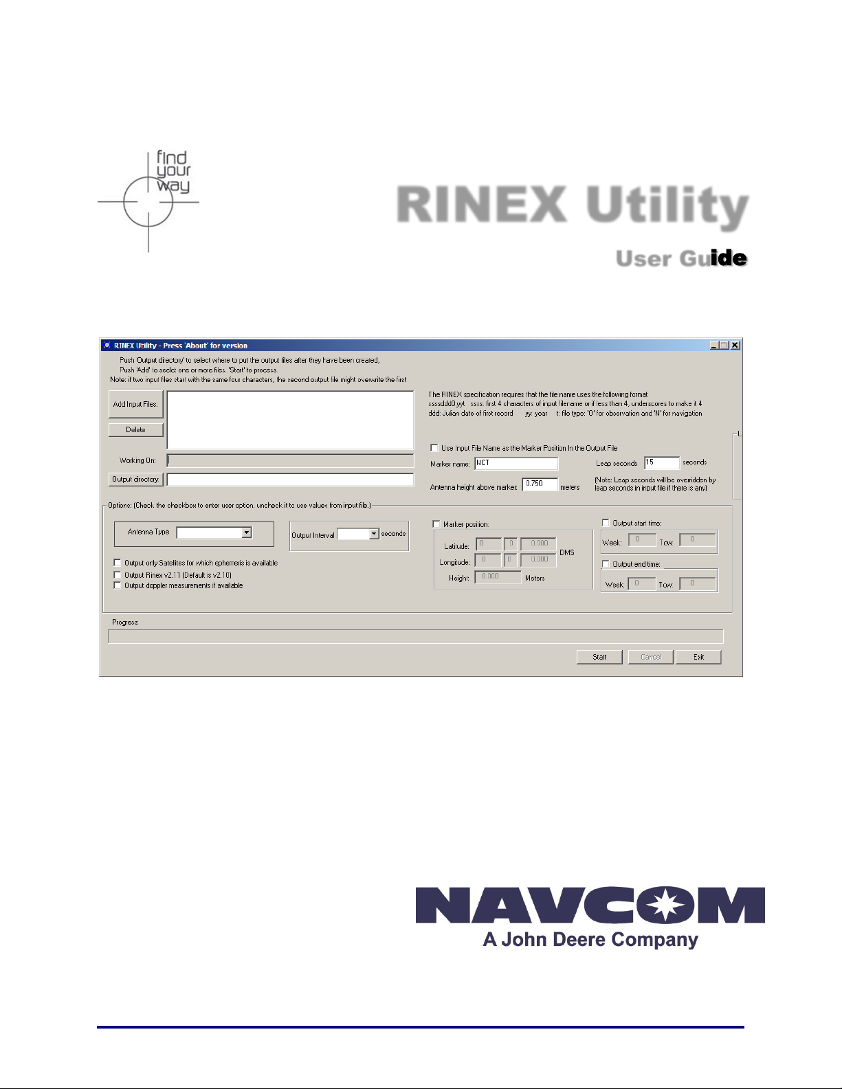
Figure 1: NavCom RINEX Utility
The NCT RINEX Utility GUI is divided into four major areas:
File I/O
User Input
Options
Execution and Progress
7
Page 9

RINEX Utility – Rev D
File I/O
Figure 2: Input File and
Output Directory
Refer to Figure 2 for the steps below:
File Naming Convention
The RINEX protocol requires a specific format for the output file. If you select multiple files with
the same first four characters, each subsequent file will over-write and “crash” those processed
earlier. This really can't be helped, and the recommended approach is to rename the input files
to each have a unique name, and then check the "use file name as marker" check box to see
the file name in the Observations file."
8
Page 10

RINEX Utility – Rev D
File Name
Field
Definition
ssssdddf.yyt
ssss:
4-character station name designator
ddd:
Julian date of the year; i.e. March 23, 2007 = Julian date 082
f:
file sequence number within day
0:
file contains all the existing data of the current day
yy:
year
t:
file type:
O: Observation file
N: Navigation file
M: Meteorological data file
G: GLONASS Navigation file
H: Geostationary GPS payload nav mess file
B: Geostationary GPS payload broadcast data
C: Clock files (see separate documentation)
Table 1: RINEX Output File Naming Convention
If the input files start with the same four characters, the resulting output files will have problems.
For example:
Input file: ANT34_13045.DAT becomes: ANT31841.11O
Input file: ANT35_13045.DAT becomes: ANT31841.11O.
This will overwrite the previous file
Input file: ANT36_13045.DAT becomes: ANT31841.11O.
This will overwrite the previous file
This is important because the standard naming convention of internal data logging files on
NavCom products is “datalog_YYYY_MM_DD_HH_MM.dat”. If the “data” portion of the file
name is not changed when multiple files are selected to process, the result will be that all the
files with the same date information will be over-written with content of the last file processed.
Figure 3: NavCom Input File Naming Convention
9
Page 11

RINEX Utility – Rev D
Leap Seconds
0 or Last Entered
Marker Name
None or Last Entered
Antenna Height
0.0 or Last Entered
Marker Position
Disabled
Output Times (Start and End)
Disabled
Sat Ephemeris when Available
Disabled
Click the Add Input Files button to bring up a browse/selection box and select each NCT
binary raw data file (*.dat) to be converted to the RINEX Standard. Each file selected will
be added to the list box next to the Add Input Files button. Multiple files can be added and
will be processed in the order listed. Once the field is full, a scrollbar will appear on the
right hand side of the field. The number of files that can be processed will depend on the
available memory.
To delete a file, click the file name to highlight it, then click the Delete button.
Be sure to name or rename the input files to avoid overwriting the output files.
Click the Output Directory button to select the folder in which to save the converted files.
Note the warning regarding duplicate file names.
Click the START button at the bottom of the screen to begin the conversion process. The
RINEX Utility will select a file one at a time from the list box, move it to the Working On field
and remove it from the list box.
The Progress bar will show the status of the conversion process. When the conversion is
complete, a prompt will appear which states Rinex Output Completed. Click OK to
continue. The process will repeat until all files have been processed.
Click the Cancel button to stop the operation.
Click the Exit button when you are finished with the conversion process.
The RINEX Utility converts the NCT data file into RINEX files that follow the RINEX naming
convention (refer to the File Naming Convention section above).
The conversion options available in the User Input and Options areas of the
RINEX Utility window are not always necessary to complete the conversion.
However, selecting the appropriate Antenna Type is always recommended
to obtain the best results (see Figure 7).
If the user enters conversion options, the headers of the RINEX files display the user
specific information. If the user does not enter options, the headers display the default
information shown in Table 2.
Table 2: RINEX Utility Defaults
These conversion options are available:
User Input: Marker Name, Leap Seconds, and Antenna Height Above Marker
Options: Marker Position, Output Start / End Times, Antenna Type, Output Interval, and
Ephemeris Output
Refer to sections User Input and
Options for details.
10
Page 12

RINEX Utility – Rev D
If no conversion options are desired, click the Start button to generate the RINEX files.
User Input
Figure 4: User Input Area
Completing the User Input fields is optional. Entries in these fields are included in the headers of
the RINEX navigation or observation files.
Figure 4 shows the User Input area of the RINEX Utility.
Use Input File Name as the Marker Position In the Output File: Clicking the checkbox allows
the input file name to be used as the Marker name.
Marker name: Allows up to 60 characters to identify the site where the data was collected.
Leap seconds: Allows the user to insert the current GPS Leap Second value, if known. If left
blank no leap second value will be reported in the RINEX ephemeris (navigation) file
header, or the RINEX Utility will use the leap second time reported in the raw data file (if one
exists). If the raw data file has a larger leap second value reported than the user entered
value, the raw data file value will be used instead.
Antenna height above marker: Allows the user to insert antenna base height above the
survey point. This adjustment can often be made in the Post Processing Software package
as well.
Options
Figure 5: Options Area
Completing the Options fields is optional. To modify an option, click the checkbox above and/or
to the left of the optional field.
Figure 5 shows the Options area of the RINEX Utility.
11
Page 13

RINEX Utility – Rev D
Marker Position: Allows the user to input the Latitude, Longitude, and Height of the surveyed
position in Degrees Minutes and Seconds. These coordinates are converted to Cartesian
ECEF format and inserted into the “Approximate Position XYZ” area of the RINEX
observation file. If left disabled, the RINEX Utility will average the position based on the
range measurements received from the total number of epochs in the data collection period.
12
Page 14

RINEX Utility – Rev D
RINEX Utility conforms to RINEX Standard 2.10, which states that the Cartesian
ECEF position in the observation file header is WGS84. This means that the height
entered in the RINEX Utility must be WGS84. The RINEX Utility makes no attempt
to convert other datum heights to WGS84. Using height data from a datum other
than WGS84 will result in errors in the Z-axis.
Output start time / Output end time: If enabled, the Output Start and Output End times allow
the user to parse a large raw data file into a smaller snap shot of the overall data collection
period. Caveats are that the GPS Week Number, and the GPS Time Of Week (TOW in
seconds) be entered. If the Output Start and Output End times are disabled, the RINEX
Utility will process the entire data collection period. If the Output Start time is set to be after
the Output End time, no processing will occur. The obverse is true for the Output end time
box.
Refer to the sections below, GPS Week Number and GPS Time, for details on
these values.
GPS Week Number
The GPS Week Number count began at midnight on the evening of 05 January 1980 / morning
of 06 January 1980. Since that time, the count has been incremented by 1 each week, and
broadcast as part of the GPS message. The GPS Week Number field in the data stream is
modulo 1024. This meant that at the completion of week 1023, the GPS Week Number rolled
over to 0 on midnight GPS Time of the evening of 21 August 1999 / morning of 22 August 1999.
The NCT-2000D and NCT-2100D use an adjusted 16-bit integer (U16) in the data to avoid this
confusion. They can handle up to week 65535.
For example, in Figure 5 the GPS Week Number for the Output Start / End times is 1313. To
determine the week/date, subtract 1024 from 1313, which is 290. Then add 290 weeks to 21
August 1999. The result is Sunday 6 March 2005.
GPS Time
The GPS time (seconds into the week) always starts on Sunday morning at 00:00 GMT. Each
24 hour period contains 86,400 seconds. A full week contains 604,800 seconds. Please see the
table below for a breakdown of hourly / daily increments.
13
Page 15

RINEX Utility – Rev D
GMT
Sun
Mon
Tue
Wed
Thu
Fri
Sat
0:00:00
0
86400
172800
259200
345600
432000
518400
1:00:00
3600
90000
176400
262800
349200
435600
522000
2:00:00
7200
93600
180000
266400
352800
439200
525600
3:00:00
10800
97200
183600
270000
356400
442800
529200
4:00:00
14400
100800
187200
273600
360000
446400
532800
5:00:00
18000
104400
190800
277200
363600
450000
536400
6:00:00
21600
108000
194400
280800
367200
453600
540000
7:00:00
25200
111600
198000
284400
370800
457200
543600
8:00:00
28800
115200
201600
288000
374400
460800
547200
9:00:00
32400
118800
205200
291600
378000
464400
550800
10:00:00
36000
122400
208800
295200
381600
468000
554400
11:00:00
39600
126000
212400
298800
385200
471600
558000
12:00:00
43200
129600
216000
302400
388800
475200
561600
13:00:00
46800
133200
219600
306000
392400
478800
565200
14:00:00
50400
136800
223200
309600
396000
482400
568800
15:00:00
54000
140400
226800
313200
399600
486000
572400
16:00:00
57600
144000
230400
316800
403200
489600
576000
17:00:00
61200
147600
234000
320400
406800
493200
579600
18:00:00
64800
151200
237600
324000
410400
496800
583200
19:00:00
68400
154800
241200
327600
414000
500400
586800
20:00:00
72000
158400
244800
331200
417600
504000
590400
21:00:00
75600
162000
248400
334800
421200
507600
594000
22:00:00
79200
165600
252000
338400
424800
511200
597600
23:00:00
82800
169200
255600
342000
428400
514800
601200
23:59:59
86399
172799
259199
345599
431999
518399
604799
Table 3: GPS Time
Example: 518400 = Sat 0:00:00 GMT
Figure 6: Output Interval and Ephemeris Option
Output only Satellites for which ephemeris is available: If enabled, the utility outputs the
ephemeris (navigation) file, but only with ephemeris data for those satellites that have been
tracked over the data collection period. If disabled the ephemeris file will contain data on all
satellites.
Output RINEX v2.11: If enabled, the utility outputs the navigation file in RINEX v.2.11
Standard. If disabled, the file will be output in RINEX v2.10. This feature enables the user
to output the file to be compatible with earlier versions of RINEX.
14
Page 16

RINEX Utility – Rev D
Output Doppler measurements if available: If enabled, Doppler measurements from
MEAS1B will be included in the conversion. Including the Doppler measurements in earlier
versions of RINEX could slow down the conversion process.
Output Interval: Select the output interval in seconds to decimally parse the data, if desired.
Figure 7: Antenna Type
Antenna Type: Select the antenna type used to collect the data. Figure 7 identifies the
NavCom antennae available in the drop-down list:
The Antenna Calibration Values for each product are available from the National
Geodetic Survey (NGS) calibration table hyperlinked to this text.
NAV_ANT3001R: The standard integrated antenna. It tracks all
GPS, GLONASS, WAAS/EGNOS/MSAS/GAGAN and
StarFire™ signals. Our compact GPS antenna has excellent
tracking performance and a stable phase center for signals.
This antenna is listed in the NOAA GPS Antenna Calibration
tables, as NAV_ANT3001R.
NAVANT3001A: The airborne integrated antenna. It tracks all
GPS, GLONASS, WAAS/EGNOS/MSAS/GAGAN and
StarFire™ signals. Our compact antenna has excellent tracking
performance and a stable phase center for all signals. This
antenna is listed in the NOAA GPS Antenna Calibration tables,
as NAVANT3001A.
NAV_ANT3001BR(SPKE): The choke ring integrated antenna.
It tracks all GPS, GLONASS, WAAS/EGNOS/MSAS/GAGAN and
StarFire™ signals. Our antenna has excellent tracking
performance and a stable phase center for GPS L1 and L2. This
antenna is listed in the NOAA GPS Antenna Calibration tables, as
NAV_ANT3001BR.
NAVSF3040: The standard integrated antenna for SF-3040
LAND-PAK receivers. It tracks all GPS, GLONASS,
WAAS/EGNOS/MSAS/GAGAN and StarFire™ signals. Our SF-
3040 GNSS sensor has excellent tracking performance and a
stable phase center for signals. This antenna is listed in the
NOAA GPS Antenna Calibration tables, as NAVSF3040.
15
Page 17

RINEX Utility – Rev D
Execution and Progress
The Start button engages the conversion process, which can be stopped at any time by clicking
the Cancel button. The Exit button closes the utility at any time, including during program
execution, thereby canceling the process.
The file being processed will be listed in the Working On field located in the File I/O section.
Figure 8: Progress of RINEX Conversion
Output Completed
When the files have been converted and stored in the output folder, the following Information
prompt will appear: RINEX output completed. Click the OK button to reset the RINEX Utility.
Figure 9: RINEX Output Completed
16
 Loading...