

Page 1

LAND-PAK™
User Guide
NavCom Technology, Inc.
20780 Madrona Avenue
Torrance, California 90503 USA
Tel: +1 310.381.2000
Fax: +1 310.381.2001
sales@navcomtech.com
www.navcomtech.com
Page 2

LAND-PAK™ User Guide – Rev. D
This page is left blank intentionally.
Page 3

LAND-PAK™ User Guide – Rev. E
Table of Contents
Table of Contents ..................................................... i
List of Figures ........................................................ iv
List of Tables ......................................................... vii
Notices .................................................................. viii
Copyright ................................................................. viii
Trademarks ............................................................. viii
FCC Notice ................................................................ ix
User Notice ................................................................ ix
Limited Warranty ........................................................ x
StarFire™ Licensing ................................................... x
USG FAR ................................................................... xi
Global Positioning System ........................................ xi
Revision History .................................................... xii
Use of This Document ......................................... xiv
Related Documents ..................................................... xiv
SF-3040 GNSS Receiver User Guide PN 96-310034-
3001 ......................................................................... xiv
SF-3040 GNSS Receiver Quick Start Guide PN 96-
310035-3001 ........................................................... xiv
LAND-PAK™ Quick Start Guide PN 96-310039-3001
.................................................................................. xv
StarUtil 3000 User Guide PN 96-310008-3001 ........ xv
Sapphire Technical Reference Manual PN 96-
3120001-3001 .......................................................... xv
RINEXUtil User Guide PN 96-310021-2101 ........... xv
Field Genius User Guide ......................................... xvi
SurvCE Integration Guide ....................................... xvi
StarPoint User Guide............................................... xvi
NavCom Release Notes .......................................... xvi
Related Standards ...................................................... xvii
ICD-GPS-200 ......................................................... xvii
GLONASS ICD, Version 5.0, 2002 ......................... xvii
NTRIP ..................................................................... xvii
RTCM-SC-104 ........................................................ xvii
CMR, CMR+ ........................................................... xvii
QZSS ...................................................................... xviii
NMEA-0183 ............................................................ xviii
Publicly Operated SBAS Signals ............................ xviii
RTCA/DO-229D ................................................. xviii
i
Page 4

LAND-PAK™ User Guide – Rev. E
WAAS (Wide Area Augmentation System) ........ xviii
EGNOS (European Geostationary Navigation
Overlay Service)................................................. xviii
MSAS (MTSAT Satellite-based Augmentation
System) ............................................................... xix
GAGAN (GPS Aided Geo Augmented Navigation)
............................................................................ xix
Chapter 1 Introduction ................................... 20
Unique Features ...........................................................20
Typical Applications ......................................................22
Land Survey and GIS ............................................... 22
LAND-PAK Configurations............................................22
NavCom SF-3040 GNSS Receiver .......................... 23
Base Station and Rover Radio Modems .................. 26
Nautiz X7 Handheld Data Collector ......................... 27
Juniper Archer 2 Handheld Data Collector ............... 31
NavCom FieldGenius ............................................... 35
NavCom CAD Basic ................................................. 35
StarPoint Post-Processing ....................................... 35
Chapter 2 Inventory Check ............................ 37
LAND-PAK UHF Survey System Inventory .............. 37
LAND-PAK GSM Network Rover Inventory ............. 40
LAND-PAK Optional Accessories............................. 42
Chapter 3 Batteries ......................................... 43
SF-3040 GNSS Receiver Battery Packs ......................43
Battery Charger LEDs .............................................. 44
SF-3040 Battery Installation .........................................45
Nautiz X7 Battery Pack .................................................47
Installing the Nautiz X7 Battery ................................ 48
Charging the Battery ................................................ 48
Chapter 4 Function Test Setup ...................... 51
Nautiz X7 Configuration ................................................51
SF-3040 UHF Radio Modem Configuration..................53
Licensing Requirements ...............................................54
Radio Overview ............................................................54
Technical Specifications ...............................................55
RF Interface .............................................................. 56
Channel Spacing ...................................................... 57
Data Speed............................................................... 57
Transmitter ............................................................... 57
Base Station Test Setup ...............................................58
Rover Test Setup ..........................................................61
ii
Page 5

LAND-PAK™ User Guide – Rev. E
Chapter 5 Field Genius ................................... 65
Summary ...................................................................... 65
Installation .................................................................... 66
Registration .................................................................. 70
SF-3040 GNSS Receiver Commands ......................... 74
Configure the Internal Radio as the Data Collector ..... 75
Perform a StarFire Quick Start .................................... 77
View StarFire Status .................................................... 80
Choose an Alternate StarFire Satellite ........................ 81
Set up StarFire Over IP ............................................... 83
Auto connect to SFOIP ................................................ 87
Reset RTK Filters ........................................................ 88
Setting Tolerances ....................................................... 90
StarFire Tolerance .................................................... 93
RTK-X Tolerance ...................................................... 95
RTK Fixed Tolerance................................................ 98
Set the Active Tolerance ........................................ 100
Chapter 6 Equipment Maintenance .............. 103
Transport ................................................................ 103
Maintenance ........................................................... 103
Battery Disposal ..................................................... 103
Safety First ............................................................. 104
A Base Station UHF Boost Radio ...................... 105
Configuration.............................................................. 106
Soft Keys ................................................................ 108
Priority RX/TX ......................................................... 109
Forward Error Correction (FEC) and Error Checking
................................................................................ 109
Operating Modes .................................................... 109
RF Frequency Configuration .................................. 111
RF Power Output .................................................... 113
Signal Threshold ..................................................... 114
Addressing Settings................................................ 115
Serial Port Settings ................................................. 116
Handshaking ........................................................... 117
Additional ................................................................ 117
B UHF Boost Radio Setup ................................. 121
C Handheld Device Specifications .................... 125
D StarFire End-User Lifetime License............... 129
E RoHS Certification .......................................... 138
RoHS 认证 ................................................................. 146
iii
Page 6

LAND-PAK™ User Guide – Rev. E
List of Figures
Figure 1: SF-3040 Connectors, Detail..................... 25
Figure 2: Nautiz X7 Handheld Device ..................... 28
Figure 3: Nautiz X7 Keypad, Detail ......................... 28
Figure 4: Nautiz X7 Data Collector Mating Connectors
....................................................................... 30
Figure 5: Nautiz X7 Pole Clamp and Cradle ........... 30
Figure 6: Nautiz X7 Mounted on the Pole Clamp .... 30
Figure 7: Archer 2 Handheld Device ....................... 31
Figure 8: Archer 2 Data Collector Mating Connectors
....................................................................... 32
Figure 9: Archer 2 Mounted on the Pole Clamp ...... 32
Figure 10: Archer 2 Keypad, Detail ......................... 33
Figure 11: LAND-PAK UHF Survey System............ 38
Figure 12: LAND-PAK Network Rover System ....... 40
Figure 13: Battery Pack Dual-Bay Charger ............. 43
Figure 14: Battery Chamber Release Button .......... 46
Figure 15: Battery Packs Installed in Chamber
Showing Locking Clips .................................... 47
Figure 16: Battery Charger/Charging Cable ............ 49
Figure 17: Windows Mobile Home Screen .............. 52
Figure 18: Windows Mobile Start Screen ................ 53
Figure 19: Radio Modem ........................................ 54
Figure 20: Base Station Tripod – Leg Adjustments . 59
Figure 21: Base Station Tripod ............................... 59
Figure 22: Mounting Tribrach & Tribrach Adapter ... 60
Figure 23: Pole Clamp and Cradle .......................... 61
Figure 24: Mounting the MicroSurvey Nautiz X7 ..... 62
Figure 25: Navcom FieldGenius icon ...................... 66
Figure 26: NavCom FieldGenius Setup Wizard ...... 66
Figure 27: End-User License Agreement ................ 67
Figure 28: Device Selection screen ........................ 67
Figure 29: Ready to Install screen .......................... 67
Figure 30: Application Downloading Complete Prompt
....................................................................... 68
Figure 31: FieldGenius Install screen ..................... 68
Figure 32: FieldGenius CAB Installed Screen ......... 69
iv
Page 7

LAND-PAK™ User Guide – Rev. E
Figure 33: Windows Mobile Today screen ............... 69
Figure 34: FieldGenius Registration screen ............ 70
Figure 35: MicroSurvey License Maintenance screen
........................................................................ 71
Figure 36: MicroSurvey Password screen ............... 71
Figure 37: Keypad ................................................... 72
Figure 38: FieldGenius Registration Key Screen ..... 73
Figure 39: Complete FieldGenius Registration screen
........................................................................ 73
Figure 40: Instrument Selection .............................. 75
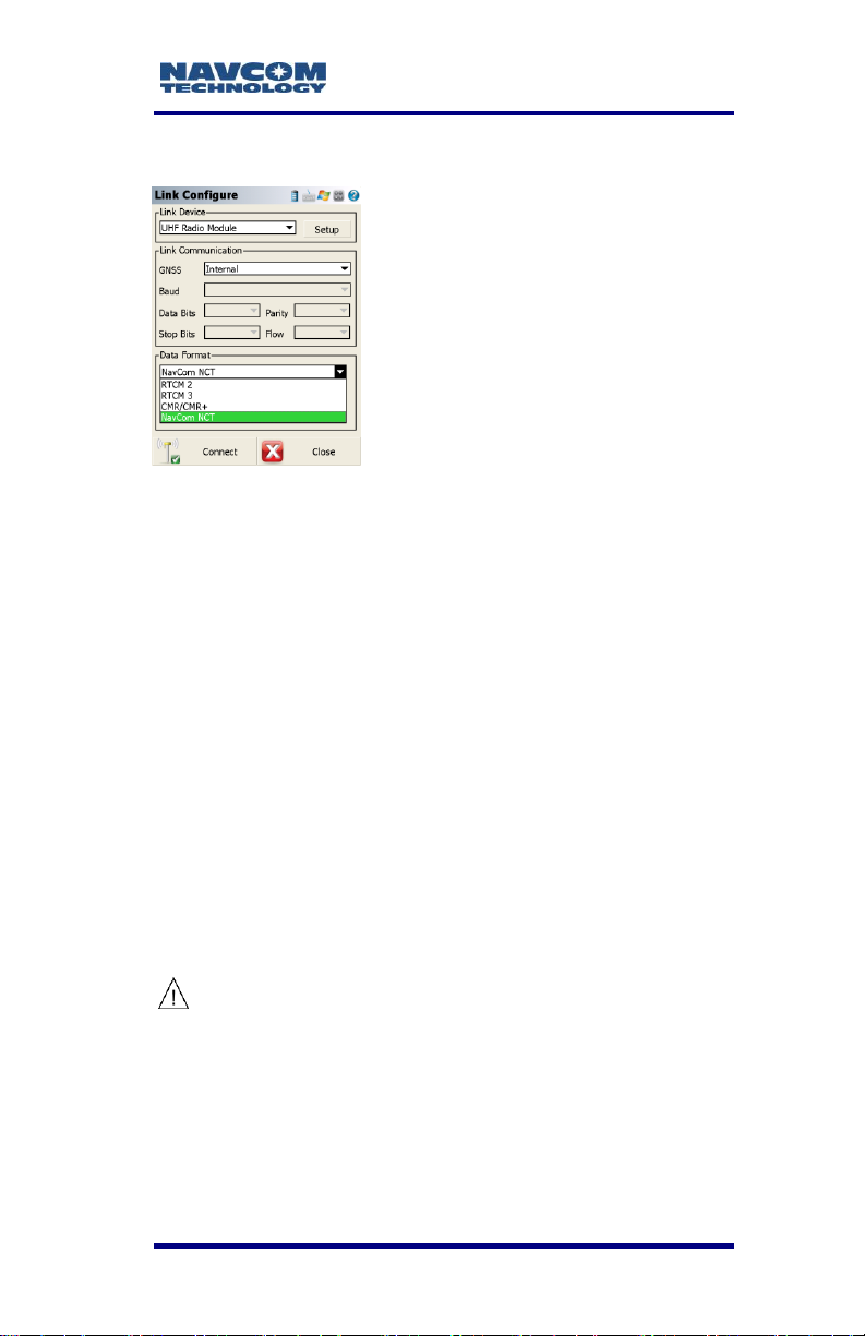
Figure 41: Link Configure ........................................ 76
Figure 42: Radio Setup ........................................... 77
Figure 43: Instrument Settings/StarFire QuickStart . 79
Figure 44: Select QuickStart Point .......................... 79
Figure 45: Instrument Settings/StarFire Status ........ 80
Figure 46: StarFire Status ....................................... 81
Figure 47: Instrument Settings/StarFire Setup ........ 82
Figure 48: StarFire Setup/Source ............................ 82
Figure 49: Instrument Settings/StarFire Setup ........ 84
Figure 50: StarFire Setup/StarFire Over IP ............. 85
Figure 51: StarFire Setup/Mountpoint Selection ...... 86
Figure 52: StarFire Setup/Auto connect to SF-IP .... 87
Figure 53: Instrument Settings/Reset RTK Filters ... 89
Figure 54: GNSS Profile/Tolerance Setting [StarFire]
........................................................................ 94
Figure 55: Tolerance 1/StarFire .............................. 94
Figure 56: GNSS Profile/Tolerance Setting [RTK-X] 96
Figure 57: Tolerance 2/RTK Extend ........................ 96
Figure 58: GNSS Profile/Tolerance Setting [RTK
Fixed] .............................................................. 99
Figure 59: Tolerance 3/RTK Fixed .......................... 99
Figure 60: GNSS Profile/Active Tolerance [StarFire]
...................................................................... 100
Figure 61: Select Tolerance .................................. 101
Figure 62: Boost Radio Wiring Diagram ................ 105
Figure 63: Radio Modem Soft Keys ....................... 108
Figure 64: LCD Display – Data Transfer Mode ...... 110
Figure 65: LCD Display – Programming Mode ...... 110
Figure 66: Active Channel ..................................... 111
v
Page 8

LAND-PAK™ User Guide – Rev. E
Figure 67: Next Digit ............................................. 111
Figure 68: Set Frequency ..................................... 112
Figure 69: Main Menu – Radio Settings ................ 113
Figure 70: TX Level Option ................................... 113
Figure 71: RF Power Output Settings ................... 113
Figure 72: Main Menu – Radio Settings ................ 114
Figure 73: Sig. Threshold option ........................... 114
Figure 74: Network Address ................................. 115
Figure 75: Main Menu – Port 1 Setting ................. 116
Figure 76: Baud Rate Setting ............................... 116
Figure 77: Baud Rate Setting Change .................. 117
Figure 78: Main Menu – Additional Setting ........... 118
Figure 79: Error Correction and Error Checking .... 118
Figure 80: SL-Commands and Priority .................. 119
Figure 81: Save Changes ..................................... 119
Figure 82: Mounting the Radio Antenna Bracket .. 121
Figure 83: Mounting the Antenna and Cable ........ 122
Figure 84: Avoiding Radiation Hazard .................. 123
Figure 85: Mounting the Cable to the Radio ......... 124
vi
Page 9

LAND-PAK™ User Guide – Rev. E
List of Tables
Table 1: Nautiz X7 Keypad Controls ....................... 29
Table 2: Archer 2 Keypad Controls ......................... 33
Table 3: LAND-PAK UHF Survey System Contents
(PN 92-310458-3001LF).................................. 38
Table 4: LAND-PAK Network Rover Parts List (PN
92-310459-3001LF) ......................................... 41
Table 5: LAND-PAK Optional Accessories .............. 42
Table 6: Battery Charger LED Indicators ................. 44
Table 7: UHF Radio Modem Specifications ............. 55
Table 8: Transmission Output Power Values, Watts
vs. dBm ........................................................... 57
Table 9: Measurement Performance ....................... 90
Table 10: LAND-PAK Base Station UHF Amplifier
(Optional) (PN 92-310460-3001LF) ............... 106
Table 11: Radio Modem LED Indications .............. 107
Table 12: Radio Modem Soft Key Functions ......... 108
Table 13: Receiver Sensitivity ............................... 109
Table 14: Nautiz X7 Handheld Device Specifications
...................................................................... 125
Table 15: Archer 2 Specifications .......................... 127
Table 16: Toxic or Hazardous Substances or
Elements Disclosure by Part Number ............ 138
表17: 按部件号列出的有毒或危险物质或原件...... 147
vii
Page 10

LAND-PAK™ User Guide – Rev. E
Notices
LAND-PAK™ User Guide
PN 96-310038-3001
Rev. E
Aug, 2014
Serial Number:
Date Delivered:
Purchased From:
Copyright
2014 by NavCom Technology, Inc.
All rights reserved. No part of this work or the
computer program(s) described herein may be
reproduced, stored, or transmitted by any means,
without the expressed written consent of the copyright
holders. Translation in any language is prohibited
without the expressed written consent of the copyright
holders.
Trademarks
‘find your way’, ‘NavCom Globe’, and ‘NAVCOM
TECHNOLOGY’ logos and ‘Land-Pak™’,
‘RTK/UltraRTK™’, and ‘RTK-Extend™’are
trademarks of NavCom Technology, Inc. StarFire™ is
a registered trademark of Deere & Company. All
other product and brand names are trademarks or
registered trademarks of their respective holders.
viii
Page 11

LAND-PAK™ User Guide – Rev. E
FCC Notice
NavCom-manufactured products comply with Part 15
of the FCC Rules. Operation is subject to the
following two conditions:
1. This device may not cause harmful
interference, and
2. This device must accept any interference
received, including interference that may
cause undesired operation.
The NavCom-manufactured products have been
tested in accordance with FCC regulations for
electromagnetic interference. This does not
guarantee non-interference with other equipment.
Additionally, the products may be adversely affected
by nearby sources of electromagnetic radiation.
The Global Positioning System (GPS) is under the
control of the United States Air Force. Operation of
the GPS satellites may be changed at any time and
without warning.
The FCC compliance of other components within this
system can be found inside the respective user
guides or by contacting the manufacturer directly.
User Notice
NavCom Technology, Inc. shall not be responsible for
any inaccuracies, errors, or omissions in information
contained herein, including, but not limited to,
information obtained from third party sources, such as
publications of other companies, the press, or
competitive data organizations.
This publication is made available on an “as is” basis
and NavCom Technology, Inc. specifically disclaims
all associated warranties, whether express or implied.
ix
Page 12

LAND-PAK™ User Guide – Rev. E
In no event will NavCom Technology, Inc. be liable for
direct, indirect, special, incidental or consequential
damages in connection with the use of or reliance on
the material contained in this publication, even if
advised of the possibility of such damages. NavCom
Technology, Inc. reserves the right to make
improvements or changes to this publication and the
products and services herein described at any time,
without notice or obligation.
Limited Warranty
NavCom warrants that its products will be free from
defects in material and workmanship at the time of
delivery. A full description of the warranty policy is
provided in NavCom’s Standard Terms & Conditions
of Sale For NavCom Products in force at the time of
sale. Please contact your NavCom dealer or NavCom
Sales for a copy of the warranty policy for your
specific product. Please include your model and serial
number, approximate date of purchase, and the
dealer name where the unit was purchased through
so that we may better service this request.
StarFire™ Licensing
The StarFire™ signal requires a subscription that
must be purchased for products other than LANDPAK in order to access the service. LAND-PAK
system purchases include a limited-lifetime StarFire
license, in that, the software currently only supports a
ten-year license. This timeframe is inclusive of the
expected serviceable life of the LAND-PAK product
and is subject to StarFire service availability.
Equipment which remains operational at the end of
the ten-year period may be relicensed in 5-year
increments beyond the initial license period. Licenses
are non-transferable, and are subject to the terms of
the StarFire™ Signal License Agreement. Additional
x
Page 13

LAND-PAK™ User Guide – Rev. E
terms and conditions may apply; for full details,
contact a NavCom dealer. For further details on the
StarFire™ Signal Network, its capabilities, terms and
conditions visit www.navcomtech.com or send an
email inquiry to sales@navcomtech.com.
USG FAR
Technical Data Declaration (Jan 1997)
The Contractor, NavCom Technology, Inc., hereby
declares that, to the best of its knowledge and belief,
the technical data delivered herewith under
Government contract (and subcontracts, if
appropriate) are complete, accurate, and comply with
the requirements of the contract concerning such
technical data.
Global Positioning System
Selective availability (S/A code) was disabled on 02
May 2000 at 04:05 UTC. The United States
government has stated that present GPS users use
the available signals at their own risk. The US
Government may at any time end or change
operation of these satellites without warning.
The U.S. Department of Commerce Limits
Requirements state that all exportable GPS products
contain performance limitations so that they cannot
be used to threaten the security of the United States.
Access to satellite measurements and navigation
results will be limited from display and recordable
output when predetermined values of velocity and
altitude are exceeded. These threshold values are far
in excess of the normal and expected operational
parameters of the SF-3040 GNSS receiver.
xi
Page 14

LAND-PAK™ User Guide – Rev. E
Rev E – Aug 2014
Chapter 1:
Changed battery specifications in
Table 2 and 3.
Added note regarding Network RTK
Added Archer 2 user information.
Chapter 2:
Added label colors to UHF antenna
in Table 3.
Chapter 5:
Changed two SFOIP servers to one
server.
Changed RTK Extend operating
time to 15 minutes for nonNavCom
bases
Added note regarding RTK Extend
maximum performance
Added specs and note for RTK-WL.
Deleted specs for StarFire Single
Added note regarding Network RTK.
Revised figures and instructions for
FieldGenius upgrade.
Appendix C:
Added Archer 2 specifications.
Rev D – Sept 2013
Chapter 2: Updated component photos
and part numbers.
Chapter 4: Added controller
configuration instructions.
Chapter 5: Updated specifications for
StarFire Single.
Added FieldGenius software
installation and registration
instructions.
Rev. C – Apr 2013
Table 8: Added tolerances for Static
Post Processing and Rapid Static
Post Processing modes.
Revision History
xii
Page 15

LAND-PAK™ User Guide – Rev. E
Eliminated all references to Galileo, E1
and E2A.
Chapter 5: Added FieldGenius
instructions for StarFire Over IP.
Chapter 5: Revised FieldGenius
instructions for StarFire Alternate
Satellite.
Trade Marks – updated
Added Appendix E: RoHS certification
(both English and Chinese)
Added Table 14: Toxic or Hazardous
Substances or Elements Disclosure
by Part Number (both English and
Chinese)
Added Note that receiver will support
SD card up to 16GB.
Chapter 3: Added note to charge
batteries for 12 hours prior to first
use.
Rev. B - Oct 2011
Chapter 1: updated Communications
with Bluetooth connectivity
information
Table 7: updated bandwidth and notes
Chapter 4: updated Channel Spacing
updated Data Speed
Table : updated Measurement
Performance with StarFire GNSS
Table 13: updated bandwidth and
sensitivity
Appendix A: updated Additional
settings
Rev. A
Initial Issue
xiii
Page 16

LAND-PAK™ User Guide – Rev. E
Use of This Document
This User Guide is intended to be used by someone
familiar with the concepts of GPS and satellite
surveying equipment.
Note indicates additional information to
make better use of the product.
This symbol means Reader Be
Careful. Indicates a caution, care,
and/or safety situation. The user might
do something that could result in
equipment damage or loss of data.
Revisions to this User Guide can be obtained in a
digital format from
http://www.navcomtech.com/Support/
Related Documents
SF-3040 GNSS Receiver User Guide
PN 96-310034-3001
Describes the features, setup, interfacing,
configuration, specifications, and operation of
NavCom’s SF-3040 receiver
SF-3040 GNSS Receiver Quick Start Guide
PN 96-310035-3001
Provides steps to quickly configure and operate the
SF-3040 GNSS receiver
xiv
Page 17

LAND-PAK™ User Guide – Rev. E
LAND-PAK™ Quick Start Guide
PN 96-310039-3001
Provides steps to configure and operate the
LAND-PAK™ with minimal setup time to the point of
collecting positions with RTK/UltraRTK™
Describes the standard configuration for the base and
rover radio modems and controller data collection
software
StarUtil 3000 User Guide
PN 96-310008-3001
Describes the operation and use of NavCom’s
Windows-based control program
Sapphire Technical Reference Manual
PN 96-3120001-3001
Describes the control and output data message
formats utilized by this instrument (for customer
programming purposes
RINEXUtil User Guide
PN 96-310021-2101
Describes the conversion program used for NavCom
proprietary output data message formats to RINEX
ver 2.10 observation and navigation files (for
customer programming purposes
xv
Page 18

LAND-PAK™ User Guide – Rev. E
Field Genius User Guide
Describes the operation and use of NavCom’s
modified version of MicroSurvey Field Genius data
collector program
SurvCE Integration Guide
Describes the installation, registration and use of
Carlson Software’s SurvCE data collection system for
Real Time Kinematic (RTK) GNSS positioning
StarPoint User Guide
Describes the operation and use of NavCom’s
modified version of Viasat’s OnPoz post-processing
program
NavCom Release Notes
Describes software updates for NavCom products.
Current and archived Release Notes are available on
the NavCom web site:
http://www.navcomtech.com/Support/DownloadCente
r.cfm?category=releasenotes.
NavCom Customer Support provides software
updates described in the Release Notes. Submit a
request for software updates via the Request Support
Web page.
xvi
Page 19

LAND-PAK™ User Guide – Rev. E
Related Standards
ICD-GPS-200
NAVSTAR GPS Space Segment / Navigation User
Interfaces Standard; ARINC Research Corporation,
2250 E. Imperial Highway, El Segundo, CA 90245
GLONASS ICD, Version 5.0, 2002
Russian Space Agency, Information Analytical Centre
Internet: http://www.glonass-ianc.rsa.ru/
NTRIP
Radio Technical Commission for Maritime Services
(RTCM) Standard 10410.0 (RTCM Paper 2002004/SC104-STD, Version 1.0 for Networked
Transport of RTCM via Internet Protocol (NTRIP)
Radio Technical Commission for Maritime Services
(RTCM) Standard 10410.1 (RTCM Paper 111-2009SC104-STD, Version 2.0 for Networked Transport of
RTCM via Internet Protocol (NTRIP)
RTCM-SC-104
Recommended Standards For Differential GNSS
Service; Radio Technical Commission for Maritime
Services, 1800 N. Kent St, Suite 1060, Arlington, VA
22209
CMR, CMR+
Compact Measurement Record; Trimble Navigation
Limited, 935 Stewart Drive, Sunnyvale, CA 94085
xvii
Page 20

LAND-PAK™ User Guide – Rev. E
QZSS
Quasi Zenith Satellite System; Japan Aerospace
Exploration Agency (JAXA), 7-44-1 Jindaiji Higashimachi, Chofu-shi, Tokyo 182-8522
NMEA-0183
National Marine Electronics Association Standard for
Interfacing Marine Electronic Devices. NMEA
National Office; 7 Riggs Avenue; Severna Park, MD
21146
Publicly Operated SBAS Signals
RTCA/DO-229D
The Radio Technical Commission for Aeronautics
(RTCA) develops consensus-based
recommendations regarding communications,
navigation, surveillance, and air traffic management
(CNS/ATM) system issues.
RTCA. 1828 L Street, NW, Suite 805, Washington DC
20036
These organizations implement the RTCA/DO-229D
standard set by RTCA:
WAAS (Wide Area Augmentation System)
U.S. Department of Transportation; Federal Aviation
Administration, 800 Independence Ave, SW,
Washington, DC 20591
EGNOS (European Geostationary Navigation Overlay
Service)
European Space Agency; 8, 10 rue Mario-Nikis,
F-75738 Paris Cedex 15, France.
xviii
Page 21

LAND-PAK™ User Guide – Rev. E
MSAS (MTSAT Satellite-based Augmentation
System)
Japan Civil Aviation Bureau; Ministry of Transport.
Kasumigaseki 2-1-3, Chiyoda-ku, Tokyo 100, Japan
GAGAN (GPS Aided Geo Augmented Navigation)
Indian Space Research Organization; Antariksh
Bhavan, New Bel Road, Bangalore - 560 094, India
xix
Page 22

LAND-PAK™ User Guide – Rev. E
Chapter 1 .............................. Introduction
This manual describes the components of the
LAND-PAK™ system and the integration of those
components and software features not covered in the
FieldGenius documentation. Refer to the Related
Documents section of this document for a complete
product description of the SF-3040 and FieldGenius,
CAD Basic, and StarPoint software.
LAND-PAK is a complete end-user system designed
for land survey applications. LAND-PAK pairs
NavCom products with complementary technologies
and solutions, providing land surveyors a complete
turnkey system that does everything from field data
collection to office processing.
Unique Features
LAND-PAK has many unique features:
A Solution That Works
The LAND-PAK data collector provides cutting-edge
hardware with the most popular and easy-to-use
software on the market, FieldGenius. The powerful
internal radio modem gives LAND-PAK a wider
coverage area, allowing for longer distances between
stations.
In addition, the LAND-PAK data collector is equipped
with an internal 3G cell modem that can be used to
access network or NTRIP RTK corrections. These
two features together with NavCom’s RTK-Extend
capability make LAND-PAK the ideal solution for all
GNSS survey applications.
The Network RTK software option allows
the receiver to generate and receive
1-20
Page 23

LAND-PAK™ User Guide – Rev. E
RTCM 1000-series messages. The
navigation algorithms are designed to
support single-base correction
configurations. Network adjusted RTK
formats are not currently supported.
Higher Accuracy and Reliability
With the internal radio modem and RTK options on
the SF-3040 receiver, LAND-PAK is capable of
performing centimeter-accurate RTK surveys. The
RTK algorithm developed by NavCom provides fast
initialization, and the NavCom ultra-compact binary
data format for RTK ensures robust data throughput.
The receiver can utilize NavCom RTK/UltraRTK™,
RTCM, Network RTCM, NTRIP, CMR and CMR+
data streams from other base stations to minimize
base-rover separation and allow for flexibility with preexisting GNSS survey systems.
GNSS Performance
The NavCom SF-3040 receivers use the NavCom
Sapphire GNSS engine. The technology is based on
NavCom’s Touchstone™ ASIC, of which more than
100,000 are in use worldwide. Incorporated are
NavCom patented interference suppression and
multipath mitigation, a 5 Hz raw data rate (up to 10
Hz1 optional), and 5 Hz geodetic-quality positioning
(up to 10 Hz1 optional).
1
Separate Software Option Required
RTK-Extend™
RTK-Extend™ enables continuous RTK-level
positioning accuracy during radio communication
outages by utilizing NavCom’s global StarFire™
corrections.
Traditionally, when an RTK rover loses
communication with the base station, it is unable to
continue to provide position updates for more than a
1-21
Page 24

LAND-PAK™ User Guide – Rev. E
few seconds, resulting in user down-time and
reduced productivity. With RTK Extend™, a NavCom
StarFire™ receiver operating in RTK mode, can
transition to RTK Extend™ mode and maintain
centimeter level positioning during communication
loss for up to 15 minutes. RTK Extend™ allows more
efficient and uninterrupted work, enabling focused
concentration on the work rather than the tools.
Complete Portable System
LAND-PAK is a highly integrated solution designed
for productivity with minimal setup time and maximum
portability. Covering the entire land survey process, it
contains a complete base and rover system for field
data collection and back office processing.
Typical Applications
The LAND-PAK system meets the needs of the
following applications:
Land Survey and GIS
Boundary Survey
Topographical Surveys in Rough Terrain
Construction Site Stake-out
High-Accuracy Data Collection for Post-Processing
Hydrographic Survey
LAND-PAK Configurations
LAND-PAK is available in the following configurations:
LAND-PAK Survey System
(PN 92-310458-3001LF)
RTK base and rover SF-3040 GNSS receivers
(one each) with internal 1W UHF modules
1-22
Page 25

LAND-PAK™ User Guide – Rev. E
NavCom handheld controller running
Windows Mobile 6 w/ internal GPRS cell
modem and Bluetooth
NavCom FieldGenius data collector software
NavCom CAD Basic desktop software
StarPoint Post-Processing desktop software
Accessories kit; range pole, cradle, chargers,
carrying cases, etc.
LAND-PAK Network Rover
(PN 92-310459-3001LF)
RTK Rover SF-3040 GNSS Receiver
NavCom handheld controller running
Windows Mobile 6 with internal GPRS cell
modem and Bluetooth
NavCom FieldGenius data collector software
NavCom CAD Basic desktop software
StarPoint Post-Processing desktop software
Accessories kit; range pole, cradle, chargers,
carrying cases, etc.
NavCom SF-3040 GNSS Receiver
LAND-PAK includes the SF-3040 GNSS receiver,
which delivers decimeter-level position accuracy
(post-convergence period) to the precise positioning
community via StarFire corrections. This unique unit
is designed to integrate easily into real-time kinematic
(RTK), field data verification, topographical surveys,
and a wide variety of surveying applications. It
resolves ambiguities at startup or on satellite
reacquisition typically within 2 seconds, and with
appropriate software options, delivers centimeterlevel position accuracy via external RTK correction
1-23
Page 26

LAND-PAK™ User Guide – Rev. E
formats. It is capable of RTK/UltraRTK™, RTCM 2.3
and 3.0 (code and phase), RTCM 3.1, types 10011012, 1019, 1020, and 1033 (Network RTK), and
CMR/CMR+ dGPS operating methods.
The receiver simultaneously accepts additional dGPS
corrections1 (WAAS, EGNOS, MSAS, GAGAN),
assuring seamless position output.
The robust SF-3040 housing has a female standard
5/8-inch BSW threaded mount (5/8-11 UNC) with a
depth of 16 mm (0.63 inch) for mounting on a
surveyor’s pole, tripod, mast, or any apparatus that
accepts the thread size.
The SF-3040 GNSS engine includes a digital ASIC to
handle high-speed signal processing.
The operating software is also capable of supporting
internal and external radio modems. Refer to Chapter
7 of the SF-3040 GNSS Receiver Product User Guide
for details on the removable radio modem. The
internal radio modem supports Satel, Pacific Crest,
and TrimTalk over-the-air modulation formats.
The receiver can output proprietary raw satellite
measurements and Position Velocity Time (PVT) data
as fast as 10Hz (optional) through two 115 kbps serial
ports with less than 20ms latency.
1
Note that the Field Genius software
disables this feature by default to avoid
errors in applications where reception of
these signals is not aligned for the area
of intended satellite operation.
The SF-3040 is operated on internal removable
batteries or on external power. Refer to Chapter 6 of
the SF-3040 GNSS Receiver Product User Guide for
details.
Integrated GNSS and L-Band Antenna
1-24
Page 27
LAND-PAK™ User Guide – Rev. E
The all-in-one housing incorporates our compact
GNSS antenna with excellent tracking performance
and a stable phase center for GPS L1 and L2. It
tracks and receives GPS (L1, L2, L2C, L5),
GLONASS (G1, G2), StarFire, and SBAS (WAAS,
EGNOS, MSAS, GAGAN) signals. The NGS
calibration table for this product is available on the
following link:
http://www.ngs.noaa.gov/ANTCAL/Antennas.jsp;jsess
ionid=3DE81666766F189AFA9D57D343082098?ma
nu=NavCom
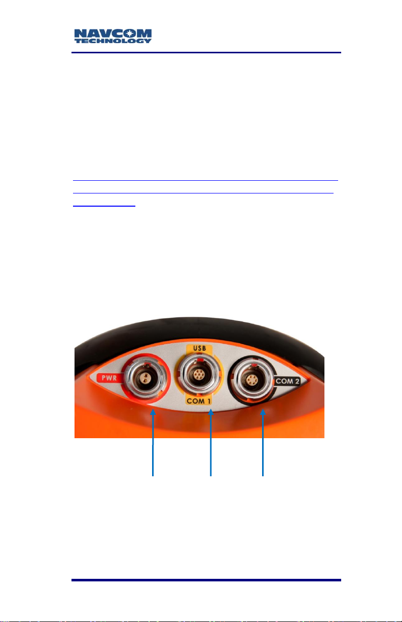
Communications
The SF-3040 provides two communication port
connectors. The 7-pin female LEMO connector
communication port, labeled USB-COM1, and the 6pin female LEMO connector communication port,
labeled COM2, are located on the bottom of the
receiver (refer to Figure 1).
POWER USB/COM1 COM2
Figure 1: SF-3040 Connectors, Detail
Each port conforms to the EIA RS-232 standard.
Available data rates are from 1.2 to 115.2kbps for the
serial ports. The USB port operates at 2.0 Mbps.
1-25
Page 28

LAND-PAK™ User Guide – Rev. E
Refer to the supplied SF-3040 GNSS
Product User Guide for further
information about the SF-3040 ports.
The SF-3040 GNSS receiver is Bluetooth-capable.
The Bluetooth module permits cable-less operation
between the receiver and the Nautiz X7 data
controller, with less than 0.2% data loss. Wireless
connectivity is provided within a range of 5 m (16 ft)
once a connection is established, and a data rate of
230.4 Kbps is supported, 10 Hz maximum. The initial
paring sequence must be conducted within 2m (6ft) of
the SF-3040. The Bluetooth interface allows
interleaved RTK data from a data collector GSM radio
modem and SF-3040 data positioning (i.e., two
communication links on one port).
Base Station and Rover Radio Modems
The LAND-PAK Survey System includes two internal
UHF radio modules that output up to 1W of power in
the 403 to 473 MHz band. The radios are digitally
synthesized and can be tuned to any in-band
frequency in 25KHz steps. An optional 35W booster
is available for the base station, but must be ordered
at the desired center frequency.
Set the radio modems only to a
licensed frequency. It must comply
with local regulatory authorities.
It is the user’s responsibility to acquire
all necessary radio licenses prior to
operation.
1-26
Page 29
LAND-PAK™ User Guide – Rev. E
User Interface
The LAND-PAK 1W radio
modems are configurable via
FieldGenius software installed
on the Nautiz X7 handheld
controller, a laptop, or a PC.
Configuration of the 35W radio
is accomplished by using the
front-panel softkeys located on
the radio.
Nautiz X7 Handheld Data Collector
The Nautiz X7 806MHz high-speed handheld data
collector features 128MB of RAM, 4GB of Flash
storage, and a 5600mAh Li-ion battery with up to 12
hours of operation on a single charge. It has an
integrated SiRF Star III GPS, Bluetooth 2.0, and
802.11b/g WLAN functionality and a built-in 3
megapixel camera with autofocus and LED flash.
With an IP67 rating, the Nautiz X7 is impervious to
dust and water and can withstand vibration, and
repeated drops. (Refer to Figure 2.)
Refer to the Nautiz X7 Quick Start Guide for detailed
instructions on getting started. Refer to Table 4 for
specifications.
Always use the supplied stylus on the
Nautiz X7 touch screen. Never use sharp
objects. Use supplied screen protectors to
increase the life of the touch screen.
1-27
Page 30
LAND-PAK™ User Guide – Rev. E
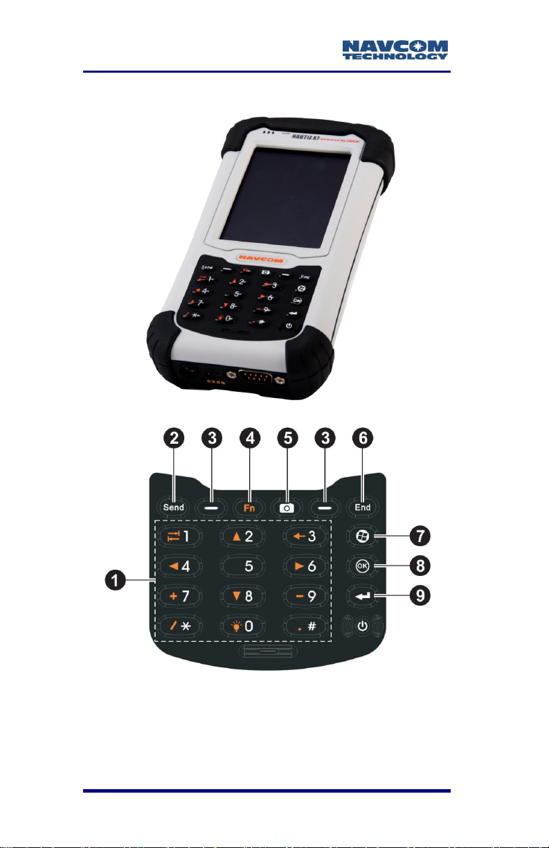
User Interface
Figure 2: Nautiz X7 Handheld Device
Figure 3: Nautiz X7 Keypad, Detail
1-28
Page 31

LAND-PAK™ User Guide – Rev. E
Ref.
Key
Description
1
Numeric
Enter numbers1
2
Send
Use for dialing or answering a call1
3
Left/Right
Softkey
Perform the command shown on the
bottom left or right corner of the screen
4
Function
Turn on/off alternate numeric key
(Fn lock is OFF by default)
Alternative
Function
Orange icons – use when Fn lock is
on (also see Item 4 in this table)
Move up, down, left, or right within the
screen or menu
Use to move between text input fields
Use to backspace over one character
in a text input field
Mathematical operators (plus, minus,
divide by, multiply)
Increase screen brightness (cycles to
lowest level after attaining highest)
5
Camera
Start the camera program (shutter
release button if the camera is in use)
6
End
End or reject a call1
7
Start
Open the Start menu
8
OK
Close the current menu or program
9
Action
Confirm your action (similar to Enter
key on a keyboard)
Table 1: Nautiz X7 Keypad Controls
1
Primarily for models with phone function; voice
communication is not a NavCom supported feature. The
intention of the cell modem is for the transfer of data (i.e.,
RTK network data).
1-29
Page 32

LAND-PAK™ User Guide – Rev. E
Refer to the Nautiz X7 Quick Start Guide
for details on using this handheld device.
Figure 4: Nautiz X7 Data Collector Mating Connectors
Figure 5: Nautiz X7 Pole Clamp and Cradle
Figure 6: Nautiz X7 Mounted on the Pole Clamp
1-30
Page 33

LAND-PAK™ User Guide – Rev. E
Juniper Archer 2 Handheld Data Collector
The Juniper Archer 2 high-speed handheld data
collector features a 1.0GHz ARM Cortex A8 i.MX53
processor, 512MB of RAM, 8GB of Flash storage,
and an intelligent 10600mAh Li-ion battery with up to
20 hours of operation on a single charge.
It has a high-sensitivity GPS/GLONASS/SBAS
receiver, Bluetooth 2.1+EDR, and 802.11b/g/n Wi-Fi
functionality with extended range and a built-in 5
megapixel camera with autofocus and LED
illuminator+video capture.
With an IP68 rating, the Archer 2 is waterproof and
dustproof.
User Interface
Figure 7: Archer 2 Handheld Device
1-31
Page 34

LAND-PAK™ User Guide – Rev. E
Figure 8: Archer 2 Data Collector Mating Connectors
Figure 9: Archer 2 Mounted on the Pole Clamp
Refer to the Archer 2 Quick Start Guide for
detailed instructions on getting started.
Refer to Table 15 for specifications.
1-32
Page 35

LAND-PAK™ User Guide – Rev. E
Button
Press and Release
Shift Function
Pictures and Videos
function; take a picture
or start and stop video
Photo and video library
(for units without a
camera)
Notes application
P1 P3
Hold-to-Zoom function
(press and hold)
Display brightness
down
Barcode scan
Buttons control panel (for
units without a barcode
scanner)
Record audio note
(press and release
then press and hold
until complete)
P2 P4
Right soft key
Display brightness up
Context Menu
Back-tab
2
2
Up (varies by screen)
Backspace (delete)
Enable or disable
touchscreen
Home screen
Start screen (toggle)
4
4
Left (varies by screen)
Figure 10: Archer 2 Keypad, Detail
Table 2: Archer 2 Keypad Controls
1-33
Page 36

LAND-PAK™ User Guide – Rev. E
Button
Press and Release
Shift Function
5 OK
5
Select OK on the
screen
6
6
Right (varies by
screen)
Return
Take picture or start
video
Perform highlighted
action (use default
action or select using
arrow keys)
Return
Take picture or start
video
Perform highlighted
action (use default
action or select
using arrow keys)
Shift (Function)
Use specific shift
function: Press and
release first, then
press and release the
button with the desired
shift function.
Turn shift function on
for all keys: Press and
release twice. To turn
shift off, press and
release again
See blue LED description
See description of the
specific button
8
8
Down (varies by
screen)
Power
Suspend/Resume
Power Button menu
(press and hold)
None
1-34
Page 37

LAND-PAK™ User Guide – Rev. E
NavCom FieldGenius
NavCom FieldGenius is designed for land surveying,
civil engineering, seismic surveying, and construction
staking professionals to provide unequalled data
collection simplicity and field calculating performance.
The graphical user interface (GUI) provides an easy
interface to build drawings as measurements are
taken, providing instant visual confirmation of
accurate data collection and survey calculations. It
includes the ability to draw line-work as
measurements from point to point are taken without
the need for cumbersome line coding.
Refer to the supplied FieldGenius User
Guide for details.
NavCom CAD Basic
NavCom CAD Basic desktop software is designed to
take the FieldGenius data for the in-office field-tofinish work and vice-versa. CAD Basic is a complete
desktop survey and design program created for
surveyors, contractors and engineers. Each LANDPAK system is supplied with a license dongle to
activate the desktop software. The program may be
installed on any number of desktop computers;
however, only computers equipped with a license
dongle may operate the software.
Refer to the supplied CAD Basic User
Guide for details.
StarPoint Post-Processing
StarPoint post-processing desktop software is
designed to take the FieldGenius and raw SF-3040
measurement data for the in-office static and rapid
1-35
Page 38

LAND-PAK™ User Guide – Rev. E
static work from recorded data. StarPoint is a
complete desktop precise point positioning program
created for surveyors, contractors and engineers.
Prior to shipment, each LAND-PAK system
identification information is loaded into a master data
base where a key-code to activate the desktop
software is generated. Upon first use, the StarPoint
software must have internet access to acquire the
registration information from the master site. If
subsequent receivers are purchased, StarPoint will
need to re-access the registration site to update
registration information. StarPoint may be installed on
any number of computers and will only process
NavCom receiver data.
Refer to the supplied StarPoint User
Guide for details.
Consult the StarPoint User Guide for
instructions on installing FieldGenius.
1-36
.
Page 39

LAND-PAK™ User Guide – Rev. E
Chapter 2 ........................ Inventory Check
This chapter provides the complete system inventory
for LAND-PAK.
The LAND-PAK Inventory Check is divided into two
sections: Survey System Inventory, Network Rover
Inventory.
If any items are missing or damaged,
immediately contact NavCom
Customer Support:
Telephone: +1 (310) 381-2000
Web:
http://www.navcomtech.com/Contact/Contact
Support.cfm
LAND-PAK UHF Survey System Inventory
Refer to Figure 11 for the items included in the LANDPAK UHF Survey System Inventory. Refer to Table 3
for a parts list.
2-37
Page 40

LAND-PAK™ User Guide – Rev. E
Ref
Item
Qty
Part Number
1
SF-3040 Receiver
2
90-209549-01
Each includes:
GPS L1/L2, GLONASS G1/G2 or L5
Navigation
5Hz standard;
10Hz1 optional, PN: 97-310041-3181
RTK, including Network RTK
RTK Extend
StarFire-enabled
License, StarFire Land Only Applications, Ten
Years Service (refer to Appendix D, section 4)
2
USB Device Cable, 6 ft
1
96-212169-01
3
COM2 Serial Cable with
1
96-212238-01
Figure 11: LAND-PAK UHF Survey System
Table 3: LAND-PAK UHF Survey System Contents
(PN 92-310458-3001LF)
2-38
Page 41

LAND-PAK™ User Guide – Rev. E
Ref
Item
Qty
Part Number
hardware handshake, 6 ft
4
Li-Ion Battery, 7.4V, 2.6Ah
4
98-214946
5
Battery Charger, Dual bay
2
98-214401
6
SD Memory Card, 2GB
2
25-212850
7
Software Documentation
USB Thumb Drive
1
82-043000-0001
-
LAND-PAK Quick Start
Guide
1
96-310039-3001
8
SF-3040 UHF Radio
Module
2
90-213034-01
9
UHF Antenna, Multiflex,
400 – 435 MHz (blue label)
435 – 470 MHz (red label)
2 98-213686
98-213687
10
Nautiz X7 GSM Handheld
Controller Kit
1
98-213016
11
Wood Fiberglass Tripod
1
98-213004
12
Fiberglass Extension Rod
1
PH98223451
13
Tribrach w/ Optical
Plummet
1
98-213006
14
Rotating Tribrach Adapter
1
PH98223452
15
Aluminum 3-Position Rover
Pole
1
98-213009
16
Clamp for Nautiz (cradle)
1
PH98223453
17
Pole Clamp for Controller
1
PH98223454
18
GPS Tape Measure
1
PH98223455
-
MS CAD Basic Dongle (not
shown)
1
98-213021
1
Separate Software Option Required
2-39
Page 42

LAND-PAK™ User Guide – Rev. E
LAND-PAK GSM Network Rover Inventory
Refer to Figure 12 for the items in the LAND-PAK
GSM Network Rover inventory. Refer to Table 4 for
the Network Rover parts list.
Figure 12: LAND-PAK Network Rover System
2-40
Page 43

LAND-PAK™ User Guide – Rev. E
Ref
Item
Qty
Part Number
1
SF-3040 Receiver
1
90-209549-01
Each includes:
GPS L1/L2, GLONASS G1/G2 or L5
Navigation
5Hz standard;
10Hz optional, PN: 97-310041-3181
RTK, including Network RTK
RTK Extend
StarFire-enabled
License, StarFire Land Only Applications, Ten
Years Service (refer to Appendix D, section
4)
2
USB Device Cable, 6 ft
1
96-212169-01
3
COM2 Serial Cable with
hardware handshake, 6 ft
1
96-212238-01
4
Li-Ion Battery, 7.4V,
2600mAh
2
98-214946
5
Battery Charger, Dual bay
1
98-214401
6
SD Memory Card, 2GB
1
25-212850
7
Software Documentation
USB Thumb Drive
1
82-043000-0001
-
LAND-PAK Quick Start
Guide
1
96-310039-3001
8
Nautiz X7 GSM Handheld
Controller Kit
1
98-213016
9
Aluminum 3-Position
Rover Pole
1
98-213009
10
Clamp for Nautiz X7
(cradle)
1
PH98223453
11
Pole Clamp for Controller
1
PH98223454
Table 4: LAND-PAK Network Rover Parts List
(PN 92-310459-3001LF)
2-41
Page 44

LAND-PAK™ User Guide – Rev. E
Ref
Item
Qty
Part Number
12
2-meter GPS Pocket
Rod/Tape Measure
1
PH98223455
-
MS CAD Basic Dongle
(not shown)
1
98-213021
Item
Qty
Part Number
SF-3040 AC/DC Adapter,
100 – 240 VAC, 12 VDC, 6 ft
1
96-212171-01
COM1 Serial Cable, 6 ft
1
96-212170-01
Aluminum Bi-Pod
1
98-213896
DC 12V cigarette lighter cable
for the Nautiz X7
1
98-213019
UHF Boost Radio Kit:
EPIC 35W IP67 Radio
High Gain Antenna
Antenna Mount
12’ GNSS Antenna Cable
6-ft Snap Lock Antenna Pole
Radio Antenna Bracket
EPIC 35W Power Cable
Radio to receiver data cable
1
1
1
1
1
1
1
1
92-310478-3001LF
PH98220542
98-213030
98-213015
94-310261-3012LF
98-213012
98-213013
98-213020
98-214267
LAND-PAK Optional Accessories
Table 5 lists available optional accessories to expand
the functional use of the two kits described above.
Table 5: LAND-PAK Optional Accessories
The receiver will support a SD card with
a maximum of 16GB (not included).
2-42
Page 45

LAND-PAK™ User Guide – Rev. E
Chapter 3 .................................... Batteries
This chapter provides guidance on battery charging
for optimum performance.
All of the LAND-PAK batteries must be
charged before the test setup of the system.
Refer to Chapter 4 Function Test Setup.
For optimum battery life and performance, it
is important that all batteries receive a full
charge before first use.
Refer to Chapter 7 Equipment Maintenance
for safety instructions regarding battery use,
storage, and disposal.
SF-3040 GNSS Receiver Battery Packs
The SF-3040 GNSS receiver is supplied with two
Lithium-ion rechargeable battery packs. The battery
charger has two charging bays (refer to Figure 13).
Figure 13: Battery Pack Dual-Bay Charger
2-43
Page 46

LAND-PAK™ User Guide – Rev. E
Off
Not charging
Red
Batteries charging
Yellow
Battery near full charge; continue
charging
Green
No battery in charger or batteries are fully
charged
Follow these steps to charge the receiver batteries:
1. Plug the supplied battery pack charger AC power
adapter into a wall outlet.
2. Connect the AC power adapter to the DC in-jack
on the supplied battery pack charger.
3. Place the battery packs in the charger.
4. Once the battery packs are fully charged, slide
them out and unplug the power.
The temperature range over which the
battery can be charged is 0C to 45C.
Charging the battery at temperatures
outside of this range may cause the
battery to become hot or to break. It
may also harm the performance of the
battery or reduce the battery’s life
expectancy.
Battery Charger LEDs
The battery charger has two LEDs, one for each
charger bay. The LED is green when no battery is in
the charger. Once a battery is placed in the charger,
the light turns red. When the battery is almost fully
charged, the light turns yellow. Continue charging the
battery. The light stays green when the battery packs
are fully charged. Refer to the below table:
Table 6: Battery Charger LED Indicators
3-44
Page 47

LAND-PAK™ User Guide – Rev. E
Batteries are not charged in the unit. If
external power is applied, the SF-3040 battery
LEDs indicate the status of the batteries, not
the status of the external power source.
Battery Charging
The SF-3040 battery packs are shipped in a
partially charged state. Complete one full
charge cycle (LED changes from red to green)
before battery use.
All new batteries must be charged for a
minimum of 12 hours prior to use, regardless
of the LED indicator on the charger.Charge
the batteries for 12-hours after each use to
ensure longest possible usage each day
If the battery packs are left charging for
longer than 5 days, the charging indicator
LEDs will shut off. If this occurs, place the
battery packs in the SF-3040 GNSS
receiver and power on for 10 to15 minutes
to slightly discharge the batteries.
SF-3040 Battery Installation
The battery chambers are located on the side of the
SF-3040 receiver. There are two locking clips on the
outside edge of each battery chamber to hold the
battery packs in place.
3-45
Page 48

LAND-PAK™ User Guide – Rev. E
Release
Button
Follow these steps to install the battery packs:
1. Open the battery pack chamber (located on the
left-hand side of the SF-3040 as you hold the
receiver with the front facing toward you) by
pressing downward on the black button.
2. Align the battery pack with the chamber.
3. Holding the locking clip to the side, insert a
battery pack into each chamber, metal-contact
end first.
4. Push the locking clips back into place.
Figure 14: Battery Chamber Release Button
5. Repeat steps 2 through 4 with the second battery
pack.
Charge the battery packs only with the
supplied battery chargers (PN 98-
214401); otherwise, damage to the
battery packs could occur.
Remove the battery packs from the
SF-3040 GNSS receivers if they will
not be used for more than one week.
Batteries are not charged in the unit. If
external power is applied, the SF-3040
battery LEDs indicate the status of the
batteries, not the status of the external
power source.
3-46
Page 49

LAND-PAK™ User Guide – Rev. E
Locking
Clip
Locking
Clip
Refer to the supplied SF-3040 GNSS
Receiver Product User Guide for
complete details on battery charging,
installation, use, safety, and disposal.
The SF-3040 GNSS receiver battery packs are keyed
to prevent improper installation. There are two locking
clips on either side of the battery bay.
Figure 15: Battery Packs Installed in Chamber
Showing Locking Clips
Ensure that both locking clips are
locked in place. If both locking clips
are not locked in place, the battery
packs can disengage.
Battery Removal
With your thumb, push a locking clip to the side (refer
to Figure 15). The battery pack should pop out
enough to be pulled free of the chamber. Repeat for
the second battery pack.
Nautiz X7 Battery Pack
This section provides steps to charge the battery
pack for the Nautiz X7.
3-47
Page 50

LAND-PAK™ User Guide – Rev. E
A 3.7V 5600mAh Lithium-Ion battery pack powers the
Nautiz X7. It can provide approximately 8 to 12 hours
of operating time on a full charge (depending on
power management and use).
There is no charging indicator on the Nautiz X7
battery charger.
Charge the battery pack only with the
supplied battery charger kit; otherwise,
damage to the battery pack could occur.
Charge the battery pack in the Nautiz X7
until it is fully charged before first use.
Installing the Nautiz X7 Battery
1. Twist the handle and remove the battery chamber
door from the back of the Nautiz X7.
2. Insert the batteries securely in the chamber.
3. Replace the battery chamber door and twist the
handle to lock it in place.
Charging the Battery
Refer to Figure 16 for the steps below:
1. Plug the DC cord of the AC adapter into the
power connector of the Nautiz X7.
2. Plug the female end of the AC power cord into the
AC adapter and the male end into an electrical
outlet.
The charge indicator glows amber when
charging is in progress and green when
the battery is fully charged.
Do not disconnect your device from AC
power until the battery is fully charged.
3-48
Page 51

LAND-PAK™ User Guide – Rev. E
Figure 16: Battery Charger/Charging Cable
3-49
Page 52

Page 53

LAND-PAK™ User Guide – Rev. E
Chapter 4 .................. Function Test Setup
This chapter provides a test setup of the LAND-PAK
before field operation to ensure system functionality.
The function test setup involves the following:
Nautiz X7 configuration
Radio modem configuration
Hardware setup
System inventory and battery charging must be
completed before this test setup. Refer to Chapter 2
Inventory Check and Chapter 3 Battery Charging.
The function test setup does not involve
satellite communication. Refer to the
FieldGenius User Guide for instructions
on initializing the system to start
collecting computed positions.
Nautiz X7 Configuration
This section provides steps to initially configure the
Nautiz X7 handheld controller prior to the installation
of the desired software.
1. Remove handheld unit from packaging and
install battery pack.
2. Press and hold power button for two seconds
to allow the unit to boot up. The Windows
Mobile home screen will appear.
3. With the stylus, tap anywhere on the Windows
Mobile home screen.
4-51
Page 54

LAND-PAK™ User Guide – Rev. E
Figure 17: Windows Mobile Home Screen
4. Follow instructions to align pointer on the align
screen. Touch and hold points with the stylus
until the cross moves.
5. On the stylus screen, click the Skip button.
6. On the date and time screen, click the Next
button.
7. On the password screen, click the Skip button.
8. On the e-mail screen, click the Skip button.
9. On the complete screen, tap the screen to
access the Windows Mobile Start screen. The
unit is now ready for software installation.
See Chapter 5: Field Genius for installation
instructions.
For SurvCE software installation, refer to
the SurvCE Integration User Guide for
instructions.
4-52
Page 55

LAND-PAK™ User Guide – Rev. E
Figure 18: Windows Mobile Start Screen
SF-3040 UHF Radio Modem Configuration
This section provides steps to initially configure the
LAND-PAK radio modems. Configuration is almost
identical for both the base station and rover radio
modems.
A 1-Watt internal, removable, user-configurable UHF
radio modem (PN 90-213034-01) is included with the
LAND-PAK system.
The UHF module is configured via the
FieldGenius software on the Nautiz X7
collector.
An optional 35W boost radio is available
for use when using the radio as a base
station and more than 1W of power is
required. The boost radio is connected
4-53
Page 56

LAND-PAK™ User Guide – Rev. E
via a com port and is not controlled via
FieldGenius; see Appendix B for details.
Licensing Requirements
This radio device requires an FCC license prior to
operation in the United States. Other countries may
have similar requirements. It is the user’s
responsibility to acquire all applicable operator
licenses.
Radio Overview
The user configures the radio via software running on
the Nautiz X7 handheld controller or a PC.
Users in North America should be
aware that the frequency band
406.0 – 406.1 MHz is for
government use only, the use of
the radio modem on this frequency
band is strictly forbidden.
4-54
Use only the radio modem supplied
by NavCom in the SF-3040.
Figure 19: Radio Modem
Page 57

LAND-PAK™ User Guide – Rev. E
Item
Receiver
Transmitter
Notes
Operating
Voltage
+3 V – +9 V
Supplied
voltage: 3.8 V
Frequency
Range
403 – 473 MHz
Channel
Spacing
12.5/20/25 KHz
1
Programmable
to 12.5 or 25
KHz
Tuning
Range
70 MHz
Sensitivity
(BER <10-3)
-110 dBm @ 12.5 KHz
-112 dBm @ 20 KHz
-112 dBm @ 25 KHz
FEC OFF2
Technical Specifications
Table 7: UHF Radio Modem Specifications
1.
Software v2.1.7 is limited to 25KHz;
Software v3.0 and later allows 12.5 or
25 KHz.
2. Due to design, the radio receiver is
4-55
about 6 – 15 dB less sensitive on the
following frequencies: 403.000,
416.000, 429.000, 442.000, 455.000,
468.000, and 469.200 MHz
Table continued on next page…
Page 58

LAND-PAK™ User Guide – Rev. E
Item
Receiver
Transmitter
Notes
Power
Consumption
<1.2 W
<3 W @ 0.5 W
output power
<7 W @ 1 W
output power
Power
Consumption,
Save Modes
Sleep: 0.24
W typical
DTR: 5 mW
Transmit Power
100, 200, 500,
1000 mW
Default:
100mW
Communication
Half-Duplex
Carrier Power
Stability
< ± 1.5 dB
Data Speed of
Serial Interface
300 – 38400 bps
Programmed
to 38400 bps
3
Modulation
4FSK (Satel), GMSK
(PacificCrest, TrimTalk)
Ant. Connector
TNC
Interface
LVTTL UART
Temperature
Ranges
-30°C – +65°C
Functional
-25°C – +55°C
Complies with
standards
-40°C – +80°C
Storage
Weight
50 g
3.
RF Interface
The radio modem has a single antenna connector
with an impedance of 50 ohm.
4-56
Software SF-3040 v2.1.7 is limited to Satel;
Software v3.0 and later allows Satel,
PacificCrest, and TrimTalk.
Not supported in the initial release of the
FieldGenius v5.1.1.2 software (initial release).
Page 59

LAND-PAK™ User Guide – Rev. E
Output Power
dBm
100 mW
+20
200 mW
+23
500 mW
+27
1 W
+30
Channel Spacing
The data speed of the radio interface depends on the
chosen radio channel spacing. Channel spacing is
fixed at 25 KHz in software v2.1.7. Software v3.0 and
later allows 12.5 or 25 KHz.
Data Speed
If the data speeds of the radio interface and the serial
interface differ, the radio modem temporarily buffers
data being transferred, so no data loss occurs.
A channel spacing of 25 KHz enables a data speed of
19200 bps. Channel spacing of 12.5 KHz enable a
data speed of 9600 bps. The TrimTalk protocol limits
the data rate to 4800bps. However, these rates are
not programmable in the SF-3040.The data speed of
the radio interface is always fixed (19200 bps),
regardless of the data speed of the serial interface.
Transmitter
The transmitter output power is adjustable: It can be
set at 100, 200, 500, or 1000 mW (1 W). To conserve
battery life, the transmitter output power should be set
to the lowest possible level that ensures error-free
connections under variable conditions.
Table 8: Transmission Output Power Values,
Watts vs. dBm
4-57
Page 60

LAND-PAK™ User Guide – Rev. E
High output power levels using short
connection distances can, in the worst case,
disturb the overall operation of the system.
The greatest allowable power
depends on the limits set by local
authorities, which limits must not be
exceeded under any circumstance.
Base Station Test Setup
This section provides steps to correctly and safely set
up the base station. It is important to select an open
area for the test setup.
The base station tripod leg points may
damage soft materials, including
indoor carpets.
1. Find a safe, open, and flat location in which to set
up the base station.
2. Unbuckle the strap that holds the tripod legs
together.
3. Open the tripod legs until the tripod is stable. Use
the tripod leg levers and the tripod wing screws to
adjust the height and secure the tripod (see
Figure 20). Leveling the tripod by eye is sufficient.
4-58
Page 61

LAND-PAK™ User Guide – Rev. E
Figure 20: Base Station Tripod – Leg Adjustments
Figure 21: Base Station Tripod
Refer to Figure 21 for the steps below:
4. Remove the tripod cap by unscrewing the tribrach
fastener.
Use the two Allen wrenches (4mm and/or 5mm,
respectively) on the top plate of the tripod to
tighten the hex screws at the top of the tripod if
needed.
4-59
Page 62

LAND-PAK™ User Guide – Rev. E
5. Store the two Allen wrenches for future use as
needed.
Figure 22: Mounting Tribrach & Tribrach Adapter
Refer to Figure 22 for the steps below:
6. Mount the tribrach to the top of the tripod as
follows:
Position the tribrach so it fits evenly on the top
plate and is flat.
Screw the tribrach fastener into the tribrach
until it is secure.
The tribrach has a leveling bubble and
three adjustment knobs to make fine
adjustments.
7. Mount the tribrach adapter into the three holes of
the tribrach, and then lock it in place by turning
the knob on the side of the tribrach.
8. Screw the pole extension into the tribrach
adapter. The pole extension provides easier
access to the connectors and exchange of the
batteries on the SF-3040 GNSS receiver.
4-60
Page 63

LAND-PAK™ User Guide – Rev. E
Rover Test Setup
This section provides the steps to correctly and safely
set up the rover. It is important to select an open area
for the test setup.
The rover pole may damage soft
materials, including indoor carpets.
Over-tightening of the attachments on
the rover pole may cause damage.
1. Set up the rover in a safe, open, and flat location.
Figure 23: Pole Clamp and Cradle
Refer to Figure 23 for the steps below:
2. Connect the rover pole clamp to the Nautiz cradle,
if necessary:
Insert the cradle quick-release adapter into
the hole in the pole clamp.
Depress the button on the pole clamp and, if
necessary, twist the cradle to the desired
position by inserting the small peg into one of
the available holes on the pole clamp.
Release the black button on the pole clamp to
lock the assembly in place.
4-61
Page 64

LAND-PAK™ User Guide – Rev. E
Figure 24: Mounting the MicroSurvey Nautiz X7
Refer to Figure 24 for the steps below:
3. Connect the clamp assembly to the rover pole:
a. Loosen the knob on the pole clamp.
b. Connect the pole clamp to the rover pole above
the level so that it does not obscure the level from
view.
c. Tighten the knob.
4. Mount the Nautiz X7 on the cradle clamp and
tighten the cradle knob.
Do not over-tighten the cradle. Over
tightening may cause damage to the
Nautiz X7 screen.
Do not lean the pole in a location
where the equipment is likely to fall.
Though the electronic products are
tested for a pole drop, repeated drops
or drops on the wrong axis may still
cause equipment damage.
5. Extend the rover pole to the maximum height
possible and snap it into place. This may require
4-62
Page 65

LAND-PAK™ User Guide – Rev. E
turning the top pole to align the spring-loaded
clasps with the bottom pole.
6. Tighten the connector at the base of the extension
to secure the extension pole.
Extending the rover pole reduces the
possibility of satellite signal blockage by
passing pedestrians or vehicles.
7. Insert the two lithium-ion battery packs into the
SF-3040 GNSS receiver. Refer to Chapter 3
Battery Charging for details.
8. Screw the receiver antenna onto the SF-3040.
9. Mount the SF-3040 to the top of the rover pole
and screw into place.
This concludes the rover test setup. Carefully,
disassemble the rover attachments, and repack all
the equipment.
4-63
Page 66

LAND-PAK™ User Guide – Rev. E
This page is left blank intentionally.
4-64
Page 67

LAND-PAK™ User Guide – Rev. E
Chapter 5 .............................. Field Genius
This chapter provides details on installing and
registering the FieldGenius software on the Nautiz 7
controller.
For Carlson Software SurvCE
installation and use, refer to the supplied
the SurvCE Integration user guide.
Summary
NavCom’s FieldGenius provides the following unique
LAND-PAK functionality:
RTK-Extend operation
StarFire Quickstart
StarFire Status
StarFire Over IP
Freeform Command Input
UHF Radio Setup
GNSS Receiver Setup
GSM Setup for Ntrip
GNSS Raw Data Logging
Receiver Status
Refer to the supplied FieldGenius User
Guide for all other information.
5-65
Page 68

LAND-PAK™ User Guide – Rev. E
Installation
NavCom’s FieldGenius software is included with the
LANDPAK kit. This software can be loaded onto the
PC desktop for easy installation.
Make sure that the Controller has been
properly configured (see Chapter 4:
Nautiz 7 Configuration) and is connected
to the PC using Windows Mobile Device
Center.
1. Double-click the navcom-fieldgenius icon on the
computer desktop.
Figure 25: Navcom FieldGenius icon
2. On the NavCom FieldGenius Setup Wizard
screen, click the Next button.
Figure 26: NavCom FieldGenius Setup Wizard
3. Click the I Accept button on the End User License
Agreement screen, then click Next.
5-66
Page 69

LAND-PAK™ User Guide – Rev. E
Figure 27: End-User License Agreement
4. Click the Windows Mobile 6 box on the Device
Selection box and click the Next button.
Figure 28: Device Selection screen
5. Click the Install button on the Ready to Install
screen.
Figure 29: Ready to Install screen
6. Allow the installation to proceed.
5-67
Page 70

LAND-PAK™ User Guide – Rev. E
7. When the Application Downloading Complete
prompt appears, click the OK button.
Figure 30: Application Downloading Complete Prompt
8. Select Device on the Windows Start screen and
Click Install.
Figure 31: FieldGenius Install screen
9. When the installation is complete, click ok to
return to the Start screen.
5-68
Page 71

LAND-PAK™ User Guide – Rev. E
Figure 32: FieldGenius CAB Installed Screen
10. Click the windows icon to access the Today
screen.
11. Scroll down to the Navcom FieldGenius icon and
click.
Figure 33: Windows Mobile Today screen
5-69
Page 72

LAND-PAK™ User Guide – Rev. E
Registration
NavCom’s FieldGenius software opens in Demo
mode. In order to take advantage of all the features,
it is necessary to register the software.
1. Click the NavCom Field Genius icon on the Today
screen to open the program to the FieldGenius
registration screen. The Device ID field will show
the unit ID code.
Figure 34: FieldGenius Registration screen
2. On the PC, access Internet Explorer
3. Type http://www.microsurvey.com/register/ into
the address bar.
4. On the MicroSurvey Software Inc. License
Maintenance screen, enter the serial number from
the GUID Quick Start Guide included in the
LANDPAK kit. Click the Submit button.
5-70
Page 73

LAND-PAK™ User Guide – Rev. E
Figure 35: MicroSurvey License Maintenance screen
5. Enter your Device ID from the FieldGenius
registration screen into the Device ID field. Enter
it again in the Confirm (Device ID) screen.
6. Click the Submit button. The Expiry Date and
Password will appear.
Figure 36: MicroSurvey Password screen
7. Access the Key Pad on the handheld unit by
doubletapping the stylus in the first Key field on
the Navcom FieldGenius registration screen
located beneath the Device ID field.
5-71
Page 74

LAND-PAK™ User Guide – Rev. E
Figure 37: Keypad
8. Enter the first four characters of the password and
click OK. Enter the next four characters and click
OK. Repeat until all 32 characters are entered
into the eight Key fields.
It is not possible to enter all 32 characters at
once. You must enter only four characters at a
time and click OK on the Keypad before entering
another four characters.
5-72
Page 75

LAND-PAK™ User Guide – Rev. E
Figure 38: FieldGenius Registration Key Screen
9. When all the fields are filled in, click the Apply Key
button. The Licensed Modules field appears to
that the registration was successful.
Figure 39: Complete FieldGenius Registration screen
5-73
Page 76

LAND-PAK™ User Guide – Rev. E
If the Invalid Key prompt appears, re-
enter the password again. If it persists,
contact Customer Service.
SF-3040 GNSS Receiver Commands
Refer to the Sapphire Technical Reference Manual
on the NavCom website for detailed information on
these commands. These commands (and others)
may be manually entered using the Freeform
Command Input feature:
[RTKDEFAULTS]
[RTKFIXMODE]
[RTKFLOATTIMEOUT]
[RTKMODE]
[RTKMULTIPATH]
[RTKNAVRESET]
[RTKSYNCMODE]
[RTKTIMEOUT]
[REFSTNPOS]
[REFNAME]
[RADIOSTAT]
[PRDGPSTIMEOUT]
[PRDGPSMODE]
[PDOPLIMIT]
[NTRIPSERVER]
[NTRIPCONFIG]
[NTRIPCLIENT]
[NAVMEASUSE]
[NAVELEVMASK]
[L1FALLBACK]
[GLONASSCORRECTION]
[GGM02STATUS]
[GGAMODE]
[DYNAMICS]
[DEFINESFSAT]
[ANTENNAHEIGHT]
[2DNAVMODE]
[STARFIREALTSAT]
[TRACKELEVMASK]
5-74
Page 77

LAND-PAK™ User Guide – Rev. E
Configure the Internal Radio as the Data
Collector
Perform these steps to configure the LAND-PAK
1W internal radio:
1. Open FieldGenius and select a project or create a
new one (see the Field Genius User Guide for
detailed instructions).
2. On the Instrument Selection dialog box (refer to
Figure 40), select GPS Rover.
The only time you select GNSS
Reference is when you are setting up a
base station with the internal 1W or
external UHF radio boost.
If the SF-3040 is not already in the
Instrument Profile list, add it to the list
first; then edit the settings. The Rover
and Reference are handled separately.
Figure 40: Instrument Selection
5-75
Page 78

LAND-PAK™ User Guide – Rev. E
3. Click Connect to connect to the SF-3040.
4. On the Link Configure dialog box (refer to Figure
41), select Internal UHF Radio as the Link
Device. The GNSS Port is Internal.
5. Select a Data Format from the drop-down list.
6. Click Connect.
Figure 41: Link Configure
7. On the Radio Setup dialog (refer to Figure 42),
set the network ID (the Base and Rover radio
network ID’s must match), type a frequency in the
Frequency text box (between 403.000 and
473.000MHz in 0.025MHz steps with 25KHz
channel spacing or 0.0125MHz steps with
12.5KHz channel spacing), and set the transmit
power.
8. Click OK.
5-76
Page 79

LAND-PAK™ User Guide – Rev. E
Figure 42: Radio Setup
9. On the Link Configure dialog box (refer to Figure
41), set the RTK correction format in the Data
Format dropdown window.
10. On the Link Configure dialog box, click Connect.
The radio is configured to transmit and receive
correction data.
Perform a StarFire Quick Start
StarFire Quick Start allows the receiver to perform as
though it is fully converged just a few moments after
startup by initializing on a known point. If a known
point is available, follow these steps to perform a
StarFire quick start:
1. Open FieldGenius and select an existing project
(see the Field Genius User Guide for detailed
instructions).
5-77
Page 80

LAND-PAK™ User Guide – Rev. E
2. On the Instrument Selection dialog box (refer to
Figure 40), select GNSS Rover.
3. Click Connect to connect to the SF-3040
receiver.
If the SF-3040 is not already in the
Instrument Profile list, add it to the list
first then edit the settings. The Rover
and Reference are handled separately.
4. On the Link Configure dialog box (refer to Figure
41), select StarFire. This sets the positioning
mode to StarFire.
5. Click Connect.
6. From the map display, click .
7. On the Instrument Settings dialog box (refer to
Figure 43), click StarFire QuickStart.
If StarFire QuickStart Reset or StarFire
Reset Cancel are displayed, cancel the
Quick Start and reinitiate StarFire
QuickStart.
5-78
Page 81

LAND-PAK™ User Guide – Rev. E
Figure 43: Instrument Settings/StarFire QuickStart
8. On the Point Database screen (refer to Figure
44), select a point ID from an existing project and
click Select to initiate a quick start.
Figure 44: Select QuickStart Point
5-79
Page 82

LAND-PAK™ User Guide – Rev. E
View StarFire Status
Perform the following steps to check StarFire status:
1. Open FieldGenius and create a project or select
an existing project (see the Field Genius User
Guide for detailed instructions).
2. On the Link Configure dialog box (refer to Figure
41), select StarFire.
3. Click Connect.
4. On the map page, click .
5. On the Instrument Settings dialog (refer to
Figure 45), select StarFire Status.
Figure 45: Instrument Settings/StarFire Status
6. On the StarFire Status dialog (refer to Figure 46),
view the StarFire parameters.
5-80
Page 83

LAND-PAK™ User Guide – Rev. E
Figure 46: StarFire Status
Choose an Alternate StarFire Satellite
After logging on to FieldGenius and selecting a
project or creating a new project, follow these steps to
change the StarFire satellite configuration:
7. On the Instrument Selection dialog (refer to
Figure 40), select GNSS Rover.
8. Click Connect to connect to the SF-3040.
9. On the Link Configure dialog box (refer to Figure
41), select None.
10. Click Connect.
11. On the map page, click .
12. On the Instrument Settings dialog (refer to
Figure 47), select StarFire Setup.
5-81
Page 84

LAND-PAK™ User Guide – Rev. E
Figure 47: Instrument Settings/StarFire Setup
Figure 48: StarFire Setup/Source
5-82
Page 85

LAND-PAK™ User Guide – Rev. E
13. Click the Source field in the General section of
the StarFire Setup screen.
14. Select StarFire from the dropdown list.
15. Click the Channel field under the StarFire section.
16. Select User-Defined and enter valid Satellite ID#
and Frequency as provided by NavCom OR
select from the available and visible alternate
satellites to force a connection OR choose Auto
Select to automatically connect to the satellite
with the strongest signal.
17. Click OK.
Set up StarFire Over IP
This feature is used to access the StarFire Over IP
network. This network consists of an independent
StarFire server which can be accessed through four
mountpoints with a choice of three data delivery
rates. This connection can be made by means of a
cellular phone modem.
Follow these steps to access the StarFire Over IP
server:
1. Open FieldGenius and select an existing project
or create a new project (see the Field Genius
User Guide for detailed instructions).
2. On the Instrument Selection dialog box (refer to
Figure 40), select GNSS Rover.
3. Click Connect to connect to the SF-3040.
4. On the Link Configure dialog box (refer to Figure
41), select None.
5. Click Continue.
5-83
Page 86

LAND-PAK™ User Guide – Rev. E
6. On the Map page, Click the tools icon .
7. On the Instrument Settings dialog (refer to
Figure 53), click StarFire Setup.
Figure 49: Instrument Settings/StarFire Setup
8. Allow StarFire Setup to complete the configuration
and dial out to the internet.
9. Access the StarFire Setup screen.
5-84
Page 87

LAND-PAK™ User Guide – Rev. E
Figure 50: StarFire Setup/StarFire Over IP
10. In the Source field, make sure that StarFire is
selected.
11. In the StarFire Over IP section, determine that the
Primary Caster and Backup Caster fields show
“Available.”
Casters are hardcoded and cannot be
changed.
5-85
Page 88

LAND-PAK™ User Guide – Rev. E
Figure 51: StarFire Setup/Mountpoint Selection
12. Select a Mountpoint from the Mountpoint
dropdown list. Four Mountpoints are available:
SFGNSSCOMPACT.1 – This option has a
frequency of one per second but delivers a smaller
data packet. Can be used when cellular signal
strength is less than optimal.
SFGNSS.1 – This option delivers the standard
StarFire data packet at the rate of one per second.
SFGNSS.15 – This option delivers the standard
StarFire data packet at the rate of one every 15
seconds.
SFGNSS.60 – This option delivers the standard
StarFire data packet at the rate of one every 60
seconds.
13. Click OK
5-86
Page 89

LAND-PAK™ User Guide – Rev. E
14. Allow the StarFire Over IP setup to complete the
configuration.
Auto connect to SFOIP
This configuration directs the software to
automatically connect to the StarFire Over IP service
if the StarFire corrections become unavailable.
1. In the Source field, select StarFire from the
pulldown list.
The checkbox is only available when
StarFire appears in the source field.
Figure 52: StarFire Setup/Auto connect to SF-IP
2. Click the checkbox next to the Auto connect to
SF-IP field.
3. Click OK
5-87
Page 90

LAND-PAK™ User Guide – Rev. E
Reset RTK Filters
This feature is used to reset the Kalman filter and
ambiguity resolution process when RTK performance
is suspected to be in error.
Follow these steps to reset the RTK filters:
1. Open FieldGenius and select an existing project
or create a new project (see the Field Genius
User Guide for detailed instructions).
2. On the Instrument Selection dialog box (refer to
Figure 40), select GPS Rover.
3. Click Connect to connect to the SF-3040.
4. On the Link Configure dialog box (refer to Figure
41), select StarFire.
5. Click Connect.
6. Click .
7. On the Instrument Settings dialog (refer to
Figure 53), click Reset RTK Filters.
5-88
Page 91

LAND-PAK™ User Guide – Rev. E
Figure 53: Instrument Settings/Reset RTK Filters
5-89
Page 92

LAND-PAK™ User Guide – Rev. E
RTK Positioning – Multi-Frequency <40kms (RMS)
Position (H):
Position (V):
+ 1cm +0.5ppm
+ 2cm +1ppm
RTK WL Positioning – Multi-Frequency <40kms (RMS)
(see note below)
Position (H):
Position (V):
+ 5cm +2ppm
+ 10cm +2ppm
RTK Extend (see note below)
Position (H):
Position (V):
+ 3cm +1ppm
+ 6cm +2ppm
RTK Float
Position (H):
Position (V):
+ 20cm +3ppm
+ 40cm +3ppm
StarFire
Position (H):
Position (V):
+ 5cm, GNSS; + 10cm, GPS
+ 10cm, GNSS; + 15cm, GPS
Code Differential GPS <200kms (RMS)
Position (H):
Position (V):
+ 45cm +3ppm
+ 90cm +3ppm
Velocity (for all DGPS described above)
Velocity:
0.01m/s
Enhanced SBAS (WAAS/EGNOS/MSAS/GAGAN) Position
Accuracy (RMS)
Position (H):
Position (V):
+ 30cm
+ 60cm
Static Post Processing Mode:
Multi-frequency; L1/L2/L2C/L5/G1/G2
Accuracy (H)
+ 3mm +0.1ppm
Setting Tolerances
Set the tolerance for all possible modes of operation.
Regardless of the user selection, StarFire and RTKExtend are automatically set as fall-back modes
unless the user configures the receiver otherwise.
Table 9: Measurement Performance
5-90
Page 93

LAND-PAK™ User Guide – Rev. E
Accuracy (V)
+ 5mm +0.5ppm
Rapid Static Post Processing Mode:
Multi-frequency; L1/L2/L2C/L5/G1/G2
Accuracy (H)
Accuracy (V)
+ 5mm +0.1ppm
+ 10mm +0.5ppm
The specifications herein are based on
the following: PDOP <4, 1-sigma (65%),
24-hour averaged set of data. Further,
performance is dependent on, but not
limited to, location, satellite geometry,
atmospheric conditions (i.e., solar storm
activity), local interference, DoD signal
degradation (i.e., Selective Availability or
similar techniques), satellite messaging
or timing errors, and augmentation
correction messages. Equipment
operated on a single frequency is more
susceptible to atmospheric and solar
storm activity than is multi-frequency
operated equipment.
The Network RTK software option allows
the receiver to generate and receive
RTCM 1000-series messages. The
navigation algorithms are designed to
support single-base correction
configurations. Network adjusted RTK
formats are not currently supported.
RTK WL is a positioning mode that is
necessary for phase ambiguity
resolution. However when this
navigation mode is indicated, it is likely
that the receiver is in a corner case
navigation condition. As such, it is not
likely that the end user will wish to use it
as a valid navigation mode.
5-91
Page 94

LAND-PAK™ User Guide – Rev. E
If the above conditions are met, then the
receiver will not need to be put into RTKWL mode.
RTK Extend uses StarFire to provide
continuous RTK positioning during nonreception of RTK corrections. When a
StarFire-enabled receiver with RTK
Extend falls out of RTK mode, the
system automatically transitions to RTK
Extend mode. Positioning is maintained
because of the close correlation in
phase measurement corrections
between RTK and StarFire.
Depending on how long the RTK base
station has been running and is StarFirefixed, the duration of RTK Extend is
limited to:
2 to 15 minutes for a NavCom
Technology base station
2 to 15 minutes for a non-NavCom
Technology base station
For RTK Extend to achieve maximum
performance, the rover must be fully
converged, which typically requires one
(1) hour of operation.
The correlation between RTK and
StarFire phase measurement
corrections decreases over time, until
the system automatically transitions out
of RTK Extend mode to the next
available dGPS mode.
This option is only required on the Rover
receiver. LAND-PAK systems are sold
with both Base and Rover optioned for
RTK Extend.
5-92
Page 95

LAND-PAK™ User Guide – Rev. E
StarFire Tolerance
Perform these steps to set the StarFire tolerance
parameters:
1. Open FieldGenius and select a project or create a
new one.
2. On the Instrument Selection dialog (refer to
Figure 40), select GNSS Rover.
3. Click Edit.
4. On the GNSS Profile dialog box (refer to Figure
28), select Tolerance Setting [StarFire].
5. On the Tolerance 1 dialog box (refer to Figure
55), set the parameters and click OK.
The recommended setting is:
Position (H): 10cm
Position (V): 15cm
When setting the above parameters,
keep the selection StarFire Dual on
the Solution drop-down list box.
5-93
Page 96

LAND-PAK™ User Guide – Rev. E
Figure 54: GNSS Profile/Tolerance Setting [StarFire]
Figure 55: Tolerance 1/StarFire
5-94
Page 97

LAND-PAK™ User Guide – Rev. E
RTK-X Tolerance
The receiver must have attained an RTK fix and have
tracked StarFire Dual mode before an RTK-X position
can be obtained. Both of these caveats normally
occur within 5 minutes of normal RTK operation.
Perform these steps to set the RTK-X (RTK-Extend)
tolerance parameters:
1. Log on to FieldGenius and select a project or
create a new one.
2. On the Instrument Selection dialog box (refer to
Figure 40), select GNSS Rover.
3. Click Edit.
4. On the GNSS Profile dialog box (refer to Figure
54), select Tolerance Setting [RTK-X].
5. On the Tolerance 2 dialog box (refer to Figure
56), set the parameters and click OK.
The recommended setting for a short
baseline is:
Position (H): 3cm
Position (V): 6cm
When setting the above parameters,
keep the selection StarFire Dual on
the Solution drop-down list box.
5-95
Page 98

LAND-PAK™ User Guide – Rev. E
Figure 56: GNSS Profile/Tolerance Setting [RTK-X]
Figure 57: Tolerance 2/RTK Extend
5-96
Page 99

LAND-PAK™ User Guide – Rev. E
When setting the above parameters,
keep the selection RTK-X on the
Solution drop-down list box.
5-97
Page 100

LAND-PAK™ User Guide – Rev. E
RTK Fixed Tolerance
Perform these steps to set the RTK Fixed tolerance
parameters:
1. Log on to FieldGenius and select a project or
create a new one.
2. On the Instrument Selection dialog box (refer to
Figure 40), select GNSS Rover.
3. Click Edit.
On the GNSSS Profile dialog box (refer to
Figure 58), click Tolerance Setting [RTK Fixed].
4. On the Tolerance 3 dialog box (refer to Figure
59), set the parameters and click OK.
The recommended setting for a long
baseline is:
Position (H): 3cm
Position (V): 6cm
When setting the above parameters,
keep the selection RTK Fixed on the
Solution drop-down list box.
5-98
 Loading...