

Page 1
LAND-PAK Quick-Start Guide
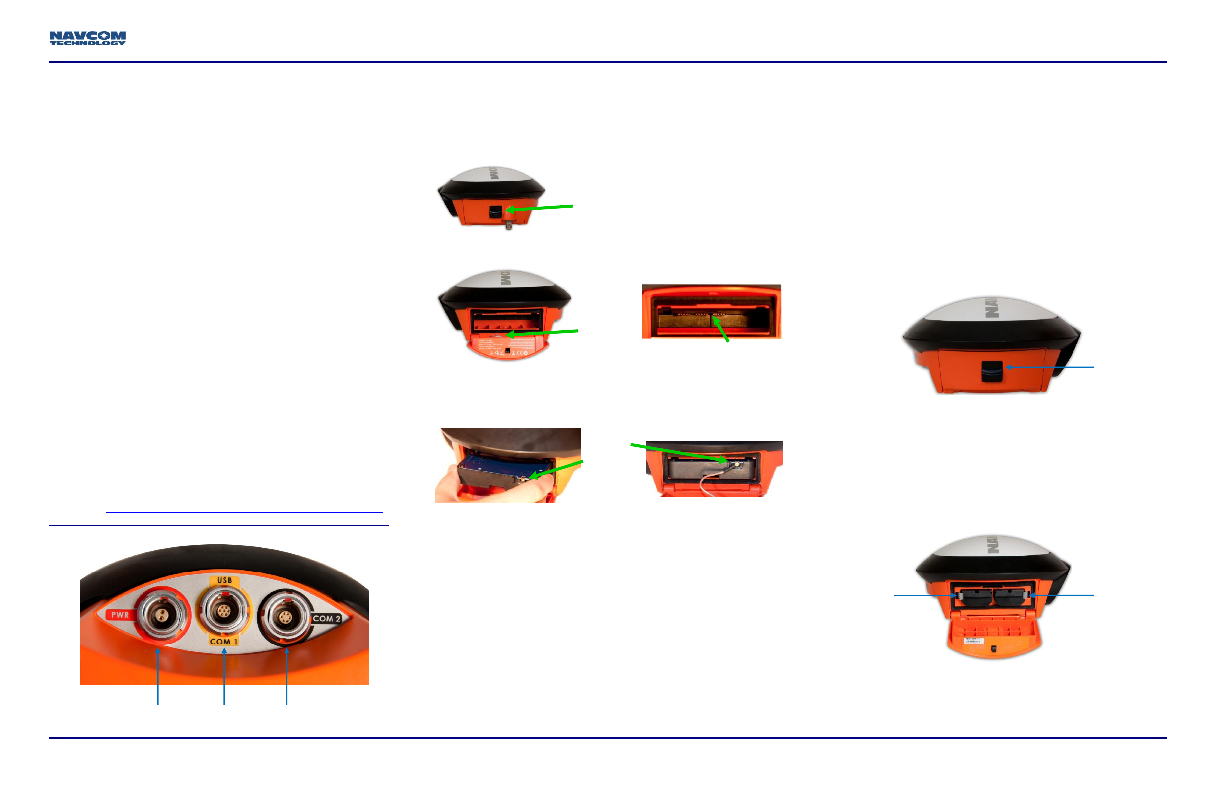
POWER
COM2
USB – COM1
MCX
Antenna
Cable
Interface Connectors
MCX
Antenna
Connector
SF-3040 Radio Bay
Release Button
Locking
Clip
Locking
Clip
Release
Button
Follow this guide to set up the standard configuration for the
LAND-PAK base and rover, and the internal radio modem.
With minimal setup time, LAND-PAK™ can be configured and
operating to the point of collecting positions with
RTK/UltraRTK™.
By opening, assembling, and using this product, you
agree to the terms of the License Agreement contained
in the LAND-PAK Product User Guide.
Important: This device will not track satellites until after
the option file is loaded in the receiver. See instructions
contained in this guide.
Refer to the supplied LAND-PAK User Guide to check
inventory, charge batteries, and set up hardware.
Refer to these supplied guides for complete instructions for
optimum performance:
NavCom LAND-PAK User Guide
NavCom SF-3040 GNSS Receiver Product User Guide
MicroSurvey Nautiz X7 User Guide
MicroSurvey FieldGenius User Guide
SATELLINE-3ASd Radio Modems User Guide
StarPoint User Guide
NavCom Customer Support:
Install UHF Radio
Follow these steps to install the radio:
1. Turn the SF-3040 off.
2. Slide the release button downward on the radio bay.
3. Insert the multi-pin end of the radio in the bay with the
contact-side up, until a click is heard.
4. Carefully align the coaxial cable MCX connector center pin
with the radio module. Press the connector on straight
with significant pressure and without damaging the center
pin.
The battery chambers are located on the side of the
SF-3040 receiver. There are two locking clips on the outside
edge of each battery chamber to hold the battery packs in
place.
Follow these steps to install the battery packs:
8. Open the battery pack chamber (located on the lefthand side of the SF-3040 as you hold the receiver with
the front facing toward you) by pressing downward on
the black button.
9. Align the battery pack with the chamber.
10. Holding the locking clip to the side, insert a battery pack
into each chamber, metal-contact end first.
11. Push the locking clips back into place.
Repeat steps 8 through 11 with the second battery pack.
Refer to the supplied SF-3040 GNSS Receiver
Product User Guide for complete details on battery
charging, installation, use, safety, and disposal.
Telephone: +1 (310) 381-2000
Web: http://www.navcomtech.com/Contact/ContactSupport.cfm
96-310039-3001, Rev. C 1 of 7
The SF-3040 GNSS receiver battery packs are keyed to
5. Route the cable to prevent pinching.
prevent improper installation. There are two locking clips on
either side of the battery bay.
6. Close the door until it clicks shut.
7. Connect the radio antenna to the TNC connector.
Refer to the SF-3040 Product User Guide for additional
detail.
SF-3040 Battery Installation
Charge the batteries in accordance with the steps outlined in
the SF-3040 Product User Guide.
New batteries must be charged for a minimum of
12 hours prior to use, regardless of the LED
indicator on the charger.
Ensure that both locking clips are locked in place.
If both locking clips are not locked in place, the
battery packs can disengage.
Page 2
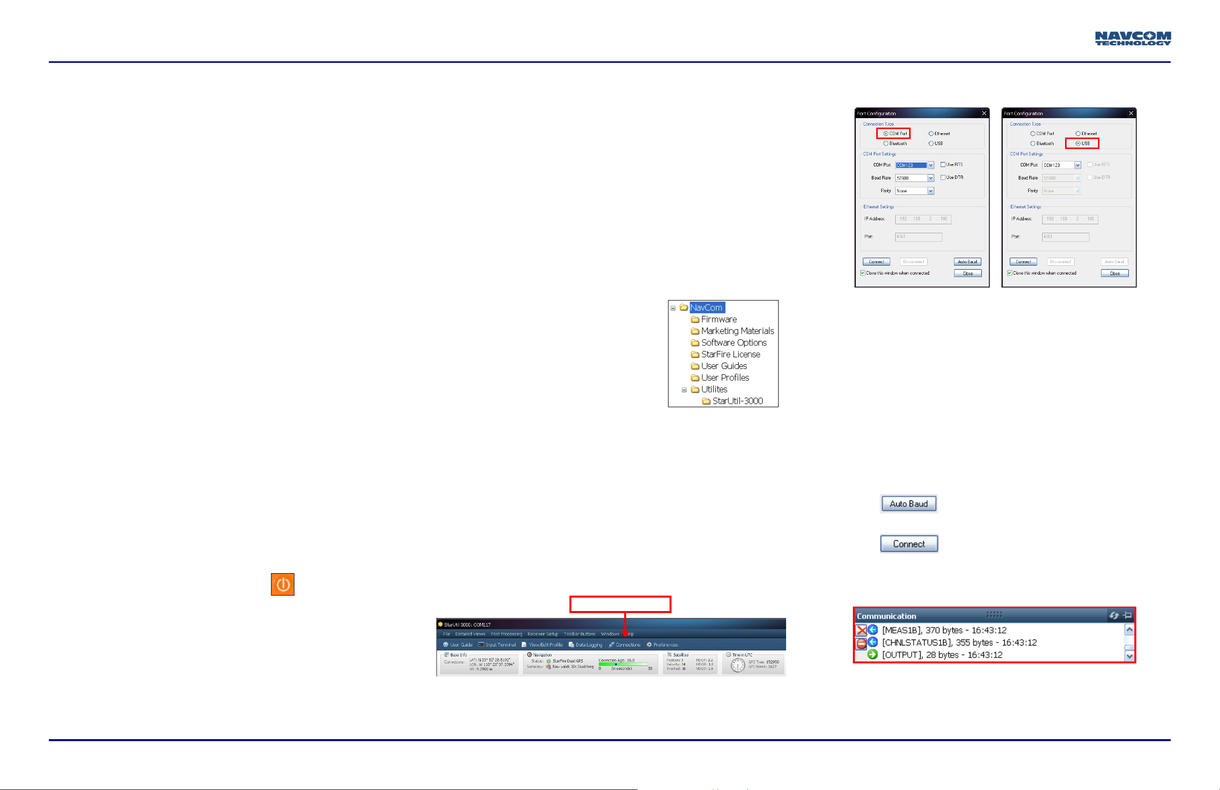
COM Port Settings
USB Settings
Connections button
Connect Equipment
12. Fully charge the battery packs in the supplied battery
charger before operation.
13. Install the battery packs in the side battery slots.
Refer to the SF-3040 GNSS Receiver Product
User Guide for complete instructions on charging
and installing the battery packs.
Three optional power cables are also available.
14. Use one of the two supplied data cables for
communications:
USB Device cable (PN 96-212238-01): Connect the 7-
pin LEMO connector end to the USB-COM1 port on
the bottom of the SF-3040. Plug the USB end into the
PC.
Or
COM 2 serial cable (optional) (PN 96-212169-01):
Connect the 6-pin LEMO connector end to COM2 port
at the bottom of the
SF-3040. Connect the DB9S end to the PC.
An optional COM1 serial cable
(PN 96-212170-01) is also supported.
Save Folder/Files to PC
The SF-3040 Product Configuration USB Flash
Drive (PN 82-043000-0001) includes the
following:
Root Directory: Software Options File and StarFire
License (if purchased)
NavCom Folder: Includes these sub-folders:
Firmware, Marketing Materials, User Guides, User
Profiles, Utilities (The contents of the NavCom folder
are subject to change.)
17. Plug the SF-3040 Product Configuration USB Flash
Drive into the PC.
18. Browse to the USB Flash Drive.
19. Save the Software Options File,
StarFire License (if purchased),
and NavCom folder to the PC.
Create two folders in the NavCom
folder for the Options File and
StarFire License.
Establish Communications
20. Browse to Navcom\Utilities\StarUtil-3000 on the PC.
24. Depending on the current Connection Type, do not
change the default option, COM Port, or select USB.
25. Set the appropriate options according to the Connection
Type:
COM Port:
COM Port: The appropriate PC COM Port
Baud Rate: 57600 (keep the default)
Parity: None (keep the default)
Or
USB Port:
Bluetooth connectivity is also available. Refer to
the StarUtil 3000 User Guide for detailed
instructions on connecting a Bluetooth device.
Loading firmware via Bluetooth is not supported.
15. Locate the receiver in an area with a 360 clear view of
the sky.
16. Press and hold the On/Off switch on the front
Indicator Panel to turn on the SF-3040. All front panel
LEDs illuminate for 3 to 5 seconds during power-up.
The Indicator Panel status LEDs change from red to
green.
2 of 7 LAND-PAK Quick-Start Guide, Rev. C
21. Ensure that these files are in the StarUtil-3000 folder:
“Starutil-3k_v1_0_x.exe”, “navcomx1c45x3040.inf”
(USB driver), and 96-312007-3001.pdf.
26. Click to ensure the baud rate is correct for
The USB driver must be in the same folder as
StarUtil-3000 for the USB port to auto-recognize
the SF-3040.
22. Double-click “Starutil-3k_v1_0_x.exe” to open the
program.
23. Click the Connections button to establish
communications between the PC and the SF-3040. The
Port Configuration window opens.
27. Click .
28. Verify that the SF-3040 is connected to the PC:
COM Port: The appropriate virtual PC COM Port
the selected port.
Messages scrolling in the Communication window
indicate that the connection is established:
Page 3

LAND-PAK Quick-Start Guide
Current NAV Firmware
NAV Firmware
Click the
Refresh
button
Firmware Info Window
Click the
Refresh
button
NAV Unified
Firmware File
Firmware in Receiver
Upload Software Options
Software Options must be uploaded before the
StarFire License (if purchased) is loaded.
Important: This device will not track satellites until after
the option file is loaded in the receiver.
29. Select Software Options on the File Upload window.
30. Click and browse to the NavCom folder on the PC.
31. Select the software options file (the file extension is
*.opt). The path to the software options file is displayed
in the upload field.
“StarFire: Enabled” indicates that the StarFire
Software Option is loaded. It does not indicate
that a StarFire License is installed. Do not close
StarUtil-3000. Perform one of these steps:
If a StarFire License is purchased, go to the
Upload StarFire License section.
If a StarFire License is not purchased, go to the
Factory Default User Profile section.
Determine Firmware Versions
The user determines that the firmware installed in the
SF-3040 is the most current. The version of the installed
firmware is important to the proper operation of the receiver.
34. On the Detailed Views menu, click Receiver Options to
open the Receiver Options tab.
Configuration USB Flash Drive. It contains the most
current firmware. The firmware file extension is *.s19.
Open the Readme.txt file for additional information.
The *.s19 file may begin with ‘SP’ instead of ‘OC’ after
January 2012.
37. Compare the current NAV Firmware version in the
Firmware folder with the installed version displayed in
the Firmware Info window.
32. Click . At the end of the upload, a
confirmation box opens. Click OK.
The Input Terminal window also displays the
outcome of the upload. In the example below, the
load is successful:
33. Click on the Software Options window to display the
loaded software options.
If any of the purchased software options are not
displayed in the Software Options window, refer to
the section “Use the Input Terminal to Upload
Software Options” in the StarUtil-3000 User
Guide.
Also refer to the Sapphire Technical Reference
Manual for detailed information on the
[INPUTSWOPTION] command.
35. Click (refresh) on the Firmware Info window to
display the installed options.
36. Browse to the NavCom\Firmware folder on the PC. The
Firmware folder is copied from the SF-3040 Product
In the example above, the NAV firmware in the
receiver matches the firmware in the folder.
38. Perform one of the steps below:
If the NAV firmware installed in the receiver is the
most current version, go to the Upload Software
Options section.
If the NAV firmware installed in the receiver is not the
most current version:
Check the versions of the other firmware.
Write down all the firmware that must be updated.
96-310039-3001, Rev. C 3 of 7
Go to the Upload Firmware section below.
Page 4

Loaded Firmware
Firmware to Load
Upload Firmware
Upload a Unified Firmware File
39. Select Unified File Loader on the File Upload window.
40. Click and browse to the NavCom\Firmware on the
PC.
41. Select the unified firmware file (UFL) to upload (the file
extension is .s19). The path to the UFL file is displayed
in the upload field.
42. Click . The options to be uploaded are
checked on the Ready to Downline Load File window.
45. When the upload is complete, click .
46. If any file fails to upload, verify which files loaded and
uncheck those files, then reload the remaining files. If
this fails, contact NavCom Customer Support for further
guidance.
Upload the StarFire License
For the initial configuration, the StarFire license
must be installed via data cable. Subsequent
renewals of the license are typically transmitted to
the receiver via radio broadcast. Refer to the SF-
3040 GNSS Receiver Product User Guide.
The receiver must be tracking GPS satellites and
providing a valid position solution at the time of
the StarFire license upload to accept the license.
47. Select StarFire License on the File Upload window.
Receiver Options tab: StarFire Licenses and Cancel
License Status windows
StarFire tab: License Info window
To open the StarFire tab, click StarFire on the
Detailed Views menu.
Confirm StarFire Navigation
52. Click Position, Velocity, Time on the Detailed Views
menu to determine if the receiver is navigating in
StarFire mode. The PVT tab opens.
43. Check or uncheck firmware files as necessary (based
on existing loaded version numbers).
44. Click and the upload progress window
updates.
48. Click and browse to the NavCom folder on the PC.
49. Select the StarFire license file (the file extension is *.lic).
The path to the StarFire license file is displayed in the
upload field.
50. Click . At the end of the upload, a confirmation
box opens. Click OK.
The Input Terminal window also displays the
outcome of the upload. In the example below, the
upload is successful.
51. Ensure that the purchased StarFire License is loaded.
These tabs provide license information:
The receiver enters StarFire mode in
Newer software versions: The Nav Mode StarFire Dual:GPS,
indicates that the receiver is navigating in the old StarFire
format, accurate to <10cm. The Nav Mode StarFire
approximately 3 minutes after it is first turned on;
then the convergence period starts.
4 of 7 LAND-PAK Quick-Start Guide, Rev. C
Page 5

LAND-PAK Quick-Start Guide
Dual:GNSS, indicates that the receiver is navigating in the
new StarFire format which supports GLONASS, accurate to
<5cm.
Older software versions: The Nav Mode StarFire Dual:RTG:
3D: Dual freq, indicates that the receiver is navigating in
StarFire dual frequency with a 3D position fix, which is very
accurate. RTG is another term for StarFire.
Figure 1: Base Station Tripod – Leg Adjustments
Figure 3: Mounting Tribrach & Tribrach Adapter
Refer to Figure 3 for the steps below:
Base Station Hardware Setup
This section provides the steps to correctly and safely set up
the base station. It is important to select an open area for the
test setup.
The base station tripod leg points may damage
soft materials, including indoor carpets.
53. Set up the base station in an open, flat, safe location.
54. Unbuckle the strap that holds the tripod legs together.
55. Open the tripod legs until the tripod is stable. Use the
tripod leg levers and the tripod wing screws to adjust
the height and secure the tripod (see Figure 1). Leveling
the tripod by eye is sufficient.
Figure 2: Base Station Tripod
Refer to Figure 2 for the steps below:
56. Unscrew the tribrach fastener and remove the tripod
cap. If necessary, use the 4 mm and/or 5mm Allen
wrench (found on the top plate of the tripod) to tighten
the hex screws at the top of the tripod.
57. Replace the Allen wrench for future use.
58. Mount the tribrach to the top of the tripod as follows:
a. Position the tribrach so that it fits flat and evenly on
the top plate.
b. Screw the tribrach fastener into the tribrach until
secure.
The tribrach has a leveling bubble and three
adjustment knobs for making fine adjustments.
59. Align the tribrach adapter with the three holes on the
tribrach, and turn the knob on the side of the tribrach to
lock it in place.
60. Screw the pole extension onto the tribrach adapter. The
pole extension allows for easier access to the
connectors and exchange of the batteries in the SF3040 GNSS receiver.
Rover Hardware Setup
This section provides the steps to correctly and safely set up
the rover. It is important to select an open area for the test
setup.
The rover pole may damage soft materials,
including indoor carpets.
Over-tightening of the attachments on the rover
pole may cause damage.
61. Set up the rover in an open, flat, safe location.
96-310039-3001, Rev. C 5 of 7
Page 6

64. Mount the Nautiz X7 on the cradle clamp and tighten
the cradle knob.
Do not over-tighten the cradle. Over tightening
may cause damage to the Nautiz X7 screen
Do not lean the pole in a location where the
Figure 4: Pole Clamp and Cradle
Refer to Figure 4 for the steps below:
equipment is likely to fall. Though the electronic
products are tested for a pole drop, repeated
drops or drops on the wrong axis may cause
equipment damage.
62. Connect the rover pole clamp to the Nautiz cradle, if
necessary:
a. Insert the cradle quick-release adapter into the hole
in the pole clamp.
b. Depress the button on the pole clamp and, if
necessary, twist the cradle to the desired position by
inserting the small peg into one of the available
holes on pole clamp.
c. Release the black button on the pole clamp to lock
the assembly in place.
65. Insert the two lithium-ion battery packs into the SF-3040
GNSS receiver. Refer to Chapter 3 (Battery Charging)
of the SF-3040 GNSS Product User Guide, if
necessary.
66. Extend the rover pole to the maximum height and snap
it into place. This may require turning the top pole to
align the spring-loaded clasps with the bottom pole.
67. Tighten the connector at the base of the extension to
secure the extension pole.
68. Extending the rover pole reduces the possibility of
satellite signal blockage by passing pedestrians or
vehicles.
69. Screw the receiver antenna onto the SF-3040.
70. Mount the SF-3040 to the top of the rover pole and
screw into place.
Bluetooth Interface
71. Log on to FieldGenius and select a project or create a
new one (see the Field Genius User Guide for detailed
instructions).
Figure 6: Instrument Selection
73. Click Edit to set the data collector interface up.
72. On the Instrument Selection dialog box (refer to
Figure 6), select GPS Rover.
Figure 5: Mounting the MicroSurvey Nautiz X7
Refer to Figure 5 for the steps below:
63. Connect the clamp assembly to the rover pole:
a. Loosen the knob on the pole clamp.
b. Connect the pole clamp to the rover pole above the
level so that it does not obscure the level from view.
c. Tighten the knob.
6 of 7 LAND-PAK Quick-Start Guide, Rev. C
a. Separate profiles are maintained in the FieldGenius
database so that one data collector can connect to
multiple devices. Select and name the unit being
configured.
Figure 7: Model and Communication
Page 7

LAND-PAK Quick-Start Guide
74. From the dropdown lists, select:
a. Make: NavCom
b. Model: SF-3040
c. Port: Bluetooth
75. Click Bluetooth Search. The display will update with
SF-3040 and the unit serial number, i.e.: SF304020024.
76. Select the appropriate device and click OK.
77. Click Connect.
Internal Radio Modem
Configuration
This section provides the steps to initially configure the SF3040 1W internal radio modem.
The only time you select GPS Reference is
when you are setting up a base station with
the internal 1 W or external UHF radio boost.
78. Click Connect to connect to the SF-3040 receiver.
79. On the Link Configure dialog box (refer to Figure 8),
select Internal UHF Radio as the Link Device. The
GPS Port is Internal, for the 1W radio only.
80. Select a Data Format from the drop-down list.
Figure 8: Link Configure
84. On the Link Configure dialog box (refer to Figure 8),
click Connect.
NTRIP Setup
Refer to the following documents (located on the USB thumb
drive) for complete information on configuring NTRIP:
NavCom WM6 Local Internet Guide.pdf
NavCom GPS GSM Profile and Bluetooth Guide.pdf
Base & Rover Survey Setup
Refer to the NavCom FieldGenius.pdf document (located on
the USB thumb drive) for complete information on
configuring the base and rover:
Base reference position
Base reference ID
Output message formats and timing
Rover mode
Authorized base ID’s
Surveying and staking points
Line work
81. Click Setup.
82. On the Radio Setup dialog (refer to Figure 9), select
the Network ID, type a frequency in the Frequency text
box (the Base and Rover frequencies and Network ID’s
must match), and select the Transmit Power. On the
Rover, set the Transmit Power to 100mW unless the
base requires the rover position for network corrections
(i.e. a periodic GGA message). In this scenario, set the
rover to match the base power out.
83. Click OK.
Field to finish work
Figure 9: Radio Setup
96-310039-3001, Rev. C 7 of 7
 Loading...