

Page 1

Vacuum Pump
NP7DP2
User Manual
S
E
RI
E
S
NAVACInc.
www.NavacGlobal.com
Tel/Fax: +1 877 MY-NAVAC
877 696 2822
MADE IN PRC
SAVE THIS MANUAL
FOR FUTURE REFERENCE
Page 2

TABLE OF CONTENTS
INTRODUCTION AND TECHNICAL INFORMATION
AC MOTOR DRIVEN VACUUM PUMPS
APPLICATION
SPECIAL FEATURES
.. ..... ..... ..... .. ... .. ... .. ... .. ... .. ... .. ..... ..... .. ... .. ... .. ... .. ... .. ... .. ...
.. ..... ..... ..... .. ... .. ... .. ... .. ... .. ... .. ..... ..... .. ... .. ... .. ... .. ...
PREPARATION PRIOR TO USING VACUUM PUMP
SAFETY WARNINGS
USE GUIDE
.. ..... ..... ..... .. ... .. ... .. ... .. ... .. ... .. ..... ..... .. ... .. ... .. ... .. ... .. ... .. ..... .
MAINTENANCE
.. ..... ..... ..... .. ... .. ... .. ... .. ... .. ... .. ..... ..... .. ... .. ... .. ... .. ... .
.. ..... ..... ..... .. ... .. ... .. ... .. ... .. ... .. ..... ..... .. ... .. ... .. ... .. ... .. ... .. .
REQUIREMENT FOR WARRANTY COVERAGE
TROUBLESHOOTING
EXPLODED VIEW
REPAIR PARTS LIST
DIMENSION
.. ..... ..... ..... .. ... .. ... .. ... .. ... .. ... .. ..... ..... .. ... .. ... .. ... .. ... .. ... .. ..... .
.. ..... ..... ..... .. ... .. ... .. ... .. ... .. ... .. ..... ..... .. ... .. ... .. ... .. ..
.. ..... ..... ..... .. ... .. ... .. ... .. ... .. ... .. ..... ..... .. ... .. ... .. ... .. ... .. ..
.. ..... ..... ..... .. ... .. ... .. ... .. ... .. ... .. ..... ..... .. ... .. ... .. ... .. ..
.. ..... ..... ..... .. ... .. ... .. ... .. ... .. ... .. ....
.. ..... ..... ..... .. ... .. ... .. ... .. ... .
.. ..... ..... ..... .. ... .. ... .. ... ..
.. ..... ..... ..... .. ... .. ... .. ... ..
01
01
01
01
02
02
03
04
04
05
06
07
08
INTRODUCTION AND TECHNICAL INFORMATION
In order to make it easier to understand the components of the vacuum pump, please see the
picture below.
Handle
Gas ballast
valve
Oil mist filter
Oil tank
Oil lens
Oil drain plug
AC MOTOR DRIVEN VACUUM PUMPS
Model
Power Supply
Flow Rate ( CFM )
Ultimate Vacuum
Pump Design
Motor Power ( HP )
Oil Capacity ( oz )
Dimensions ( in )
Weight ( lbs )
Inlet Port
APPLICATION
NAVAC dual-stage rotary vane vacuum pumps are used to remove air, moisture, and other noncondensables from sealed HVACR systems. The products can be used for evacuation of HVACR
repair and new installations, specially designed for A2L refrigerants such as, R-32, 1234yf, R-600a,
R-452B. It can also be used as other common refrigerants such as, R-12, R-22, R-410A, R-404A, R-
134A, etc.
NP7DP2
115V/60Hz
7 CFM
15 Micron
Dual-Stage, AC Motor
3/4
15
14"×5"×11.3"
26
1/4", 3/8", 1/2" Flare
Inlet
Power switch
Rear cover
Motor
Base
SPECIAL FEATURES
- Integrated pump structure, high precision, for deep ultimate vacuum level.
- Forced oil lubrication ensures vane sealing, cooling and high reliability.
- Large and easy to see oil-level window design help prevent oil supply shortage.
01
Page 3

PREPARATION PRIOR TO USING VACUUM PUMP
GROUNDING INSTRUCTIONS
This product must be grounded. In the event of an electrical short circuit, grounding reduces the risk of
electric shock by providing an escape wire for the electric current. This product is equipped with a cord
having a grounding wire with an appropriate grounding plug. The plug must be plugged into an outlet
that is properly installed and grounded in accordance with all local codes and ordinances.
WARNING:
Improper installation of the grounding plug is able to result in a risk of electric shock. When repair or
replacement of the cord or plug is required, do not connect the grounding wire to either flat blade
terminal. The wire with insulation having an outer surface that is green with or without yellow stripes is
the grounding wire.
Check with a qualified electrician or serviceman when the grounding instructions are not completely
understood, or when in doubt as to whether the product is properly grounded. Do not modify the plug
provided; if it does not fit the outlet, have the proper outlet installed by a qualified electrician.
GROUNDED
OUTLET
GROUNDING
PIN
Note: In order to prevent pump oil from spilling out, please add oil slowly.
Switch on the power and the pump will begin to operate. After running for approximately one minute,
check the oil level. If the oil level is too low, switch off the machine and add the required extra oil.
Reinstall the oil fill cap.
Note: While the pump is operating, the oil level should be in between the two oil position lines. If the
oil level is too low, it will reduce the performance and could damage the pump vanes. If the oil
level is too high, it could cause oil to discharge through the pump exhaust.
SAFETY WARNINGS
WARNING:
This machine should only be used for evacuation of refrigerant systems after refrigerant has been
removed from the system and the system has been opened to atmosphere. This machine is not to be
used as a transfer pump for liquids or any other media; doing so can damage the product.
Note: In order to avoid personal injury, please carefully read and follow the instructions in this user
manual and the user guide of the pump.
NAVAC VACUUM PUMPS ARE NOT ALLOWED TO BE USED FOR A3 OR FLAMMABLE
REFRIGERANTS.
1. NEVER CONNECT A VACUUM PUMP TO A PRESSURIZED SYSTEM. Always check to make
sure that system and piping pressure is NOT ABOVE ATMOSPHERIC PRESSURE.
2. When handling refrigerants, please wear an eye-protection such as safety glasses or goggles.
3. Avoid direct physical contact with refrigerants, you will get burned.
4. When connecting the power source, all equipments must be grounded in order to prevent
electrical hazards.
5. When the pump is in operation, the enclosure surfaces will be hot. Do not touch the oil box or the
motor case. Allow adequate ventilation space for heat dissipation.
6.Not applicable for flammable refrigerants in A2 and A3 classes.
7. Keep pump dry and away from water, mud, and dir t at all times.
8. Operating pump with intake fittings open to the atmosphere must not exceed 3 minutes.
9. Ambient temperature range for pump use is 30 to 104°F (-1°C~40°C). The pump can be used in
lower ambient conditions, if warmed up inside first and run for no more than 1 minute to warm the
oil prior to system evacuation.
10. The power outlet must be grounded.
11. Prior to connecting the vacuum pump to an A/C-R system, please use proper methods to
remove refrigerant from a pressurized system. Note that pumping refrigerants under
high-pressure conditions will damage the pump, and refrigerant must be removed using a
recovery machine designed for that pur pose.
02
03
Page 4
USE GUIDE
CAUTION
-To reduce the risk of electric shock, do not expose to rain.
Store indoors.
EXTENSION CORDS
If an extension cord must be used, be sure it is:
1. A 3-wire extension cord that has a 3-blade grounding plug, and a 3-slot receptacle that will accept
the plug on the product
2. In good condition
3. No longer than 50' (15.2m)
4. 16 gauge (AWG) or larger. (Wire size increases as gauge number decreases. 14 AWG and
12AWG may also be used. DO NOT USE 18 AWG )
NOTICE: Risk of Property Damage. The use of an undersized extension cord will cause voltage to
drop resulting in power loss to the motor and overheating.
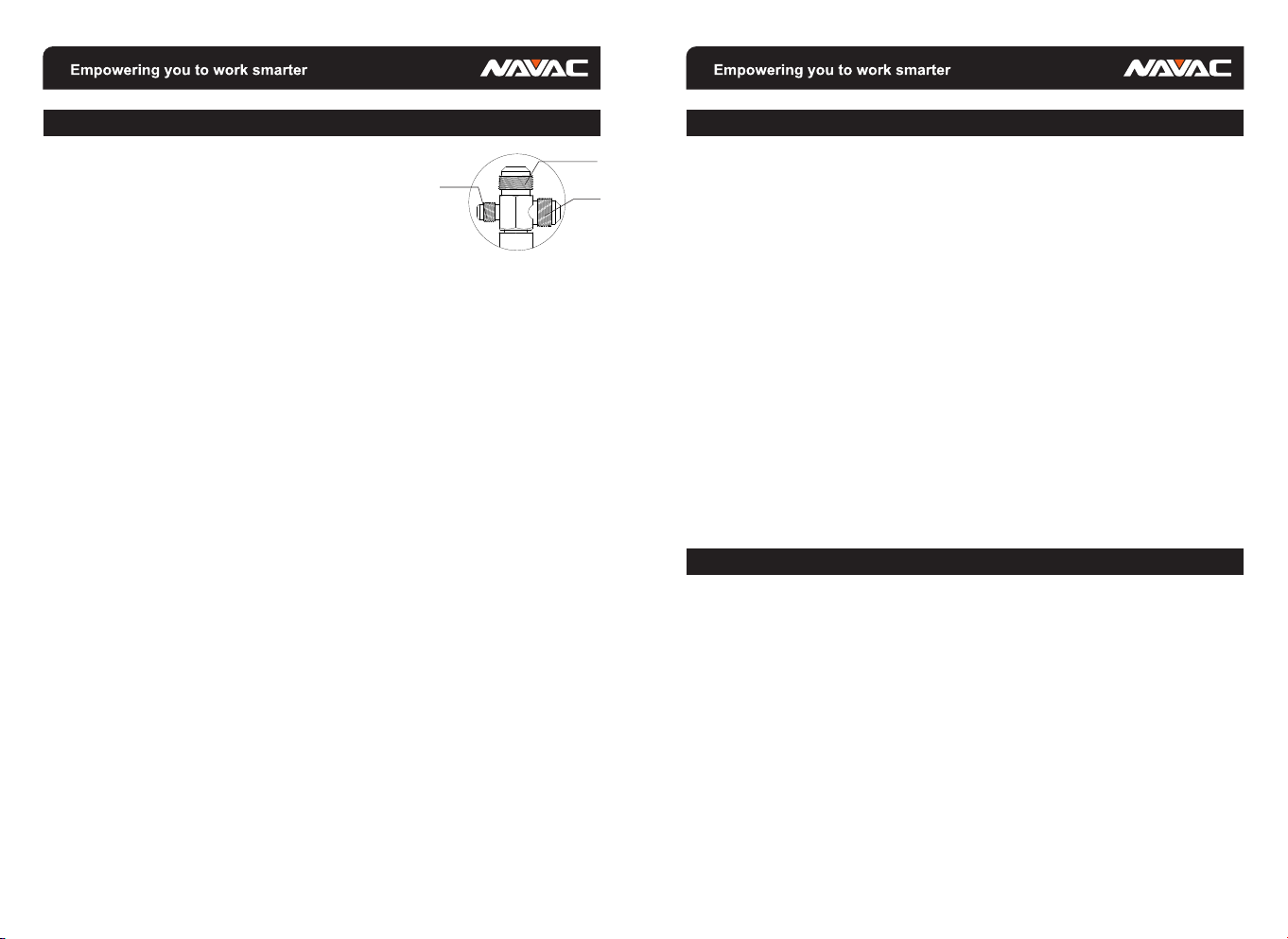
1. When using the vacuum pump, remove the inlet protection cap from the desired (1/4", 3/8", or 1/2")
connecting port, as shown in the diagram above, and connect the pump to the system or piping to be
evacuated. Use shortest hoses possible for faster and more thorough evacuation.
2. Inspect the hose inlet connection, as well as all connecting hoses for proper seal. There must be
no leakage or it will be impossible to draw the required deep vacuum level.
3. At the beginning of the evacuation process, open the GAS BALLAST, and once the vacuum
gauge reaches 2000 microns, retighten to achieve desired vacuum level.
4. After evacuation is completed, shut down the pump and close the system access valves.
5. Turn off the power switch on the pump and disconnect power.
6. Remove the evacuation hoses.
7. Close the air entry cap and the air exhaust cap tightly (with the exception of models without air
exhaust cap), to prevent dirt or particulates from entering the pump.
Note:
1. Always evacuate systems in conjunction with a micron vacuum gauge, such as the NAVAC
NMV1, giving you a comprehensive view of the sealed system internal evacuation condition.
2. Please pay attention to any changes in the oil level during pump operation. If the oil level falls
below the center line, immediately add more vacuum pump oil to avoid damage to the pump.
3. Vacuum pump and oil must be above 30℉.
1/4"
1/2"
3/8"
MAINTENANCE
1. Vacuum pump oil has three major functions: pump lubricant, pump cooling, and pump sealant.
During the evacuation process, the pump oil will absorb moisture being pulled from the system,
causing it to be less effective as a lubricant and pump vane seal, extending evacuation time and
possibly allowing the pump to overheat. We recommend that the oil be changed just before
evacuating each A/C-R system to insure the pump oil is in a clean condition as this is the key factor
in determining if the pump can achieve the required vacuum levels. In order to maintain the
optimum operation of the pump, we recommend that you use NAVAC vacuum pump oil. This oil is
made using a unique process and can maintain proper viscosity during normal operation and
temperatures, and it’s also helpful for cold starts. Should the NAVAC oil not be available, reputable
brands of special-purpose vacuum pump oil may be used.
Note: Should the pump oil become opaque, dirty, or full of moisture, promptly change oil. This will
greatly speed up evacuation, especially when there is a lot of moisture in system piping from
having been left open to the atmosphere for an extended period of time.
Oil change procedure:
1. To ensure that the pump and oil are warm, run pump for approximately one minute prior to
changing oil. Do not run longer than this, as it may be possible to damage the pump.
2. While the pump is running, open one inlet port and allow oil to drain out of the pump. After turning
off pump, open the oil drain plug, and drain used oil into an appropriate vessel and dispose of
properly.
3. As oil stops draining, tip the pump to drain any remaining oil in the bottom of the pump.
4. Close oil drain valve.
5. Remove oil fill cap, pour in new oil until the oil is at the proper level in the sight glass (the same
procedure prior to using the pump above).
REQUIREMENTS FOR WARRANTY COVERAGE
Product warranty is provided for product quality problems for one years from date of sale. For
warranty to be valid, the following conditions must be met:
1. Products issues due to manufacturing defects confirmed by qualified agents.
2. Products which have not been maintained or dismantled by unauthorized parties.
3. Products that have been used in accordance with the User Manual. All maintenance services shall
be performed during the warranty period.
Statement: Other than repairing the product defective, the manufacturer of this product will not be
liable for any other costs, such as time spent in fixing the issue, refrigerant consumption,
refrigerant disposal costs, as well as unauthorized transportation and labor costs.
0504
Page 5

TROUBLESHOOTING
Malfunction
Low
Vacuum
Oil leak
Oil spray
Start-up
problems
Notes:
1. The pump has over-current / overload protection, please troubleshoot after overload resets.
2. If the above methods cannot resolve your problems, please contact your nearest distributor or take the pump to a
repair center. We will do our best to provide you with a quick turnaround to keep you working.
1. Secondary air inlet connection cap loose on the
air inlet port.
2. Damaged rubber ring inside the secondary air
inlet connection cap.
4. Pump oil becomes opaque or absorbed too
many impurities.
6. The pump connecting hoses, manifold or
system has a leak.
7. The pump selection is wrong.
8. The pump has been used for too long, damage
and wear to components caused increased
gaps between parts.
1. Damaged oil seal.
2. Loose or damaged oil box connections.
1. Excessive oil volume.
2. Inlet port pressure is excessively high for a long
period.
1. Oil temperature is too low.
2. Motor, power source or circuit board
malfunctions.
3. Foreign objects entered the pump.
4. Voltage supply is excessively low or high.
5. Overload trips.
Possible Cause
Tighten the cap.
Replace the rubber ring.
Add oil to the center line of the oil display.
Replace with new oil.
Clean the oil entry hole, clean the oil filter.
Inspect the connecting hose gaskets and
system, repair leaks.
Check the size of the container to be evacuated,
recalculate and select an appropriate pump
model.
Inspect and repair, or replace the pump.
Replace the oil seal.
Tighten the connecting screws, replace O-rings.
Remove oil until the oil position line is reached.
Select an appropriate pump, increase the
pumping speed.
Place the vacuum pump in an over 77°F
ambient environment for an hour, or replace
in the 77°F oil.
Inspect and repair.
Inspect and remove.
Inspect the power source voltage.
Afterr overload trip occurs, turn off the switch.
Romove the power plug. Examine and solve
the issue.
Remedy
EXPLODED VIEW
0706
Page 6

REPAIR PARTS LIST
DIMENSION
Ref No.
1
2
3
4
5
6
7
8
9
10
11
12
13
14
15
16
17
18
19
20
21
22
23
24
Part No. Part Name
P040001
P040002
P040003
P040004
P040005
P040006
P040007
P040008
P040009
P040010
P040011
P040012
P040013
P040014
P040015
P040016
P040017
P040018
P040019
P040020
P040021
P040022
P040023
P040024
Oil Drain
Oil Housing
Exhaust Filter and Noise Reducer
Pump Body
Rubber Tube
Jump Ring
Hook
Nut
Handle
Gas Ballast
Inlet Port
Running Capacitor
Top Cover
Plate
Start Capacitor
Pedestal
Rear Cover
Power Cord
Switch
Fan
Motor
Plate
Rubber Feet
Electronic Starter
Unit: inch
Model
NP7DP2 14 8.3 2.8 5 3.7 11.3 7.2
A
A1 A2 B B1 H1
H
0908
 Loading...