

Page 1
Document NO. M-7001A-EM-English
PAGE Page 1 of 18
Engineer Manual-Trouble Shooting
VERSION C
ENGINEER MANUAL FOR
AFTER SALE SERVICE
PRODUCT:TREADMILL
MODEL: M-7001 SERIES A TYPE
Page 2
Document NO. M-7001A-EM-English
PAGE Page 2 of 18
Engineer Manual-Trouble Shooting
VERSION C
INFORMATION GUIDE:
1. Information For Components & System
1.1. System wiring diagram ----- Page 3
1.2. Console PCB ----- Page 4~5
1.3. Inverter ----- Page 5
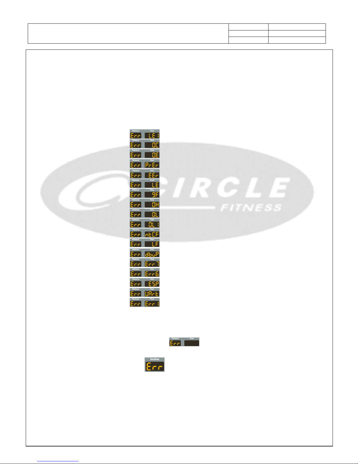
2. Error Signal Check And Solutions
2.1. Error message『LE1』 ----- Page 6
2.2. Error message『OC』 ----- Page 6
2.3. Error message『OE』 ----- Page 6
2.4. Error message『PrEr』 ----- Page 6
2.5. Error message『EEr』 ----- Page 6
2.6. Error message『LE』 ----- Page 6
2.7. Error message『9F』 ----- Page 6
2.8. Error message『OH』 ----- Page 7
2.9. Error message『OL』 ----- Page 7
2.10. Error message『OL1』 ----- Page 7
2.11. Error message『ntcF』 ----- Page 7
2.12. Error message『LF』 ----- Page 7
2.13. Error message『dbuP』 ----- Page 7
2.14. Error message『Err7』 ----- Page 7
2.15. Error message『Err6』 ----- Page 8
2.16. Error message『ESP』 ----- Page 9
2.17. Error message『UArt』 ----- Page 10
2.18. Error message『Err1』 ----- Page 11
3. Other Information
3.1. Console no power(No any display) ----- Page 12
3.2. Distance window shown『Err』only ----- Page 12
3.3. Console work normally but motor can not move ----- Page 12
3.4. Incline window show『Err』 ----- Page 13
4. Engineering Mode
4.1. Engineering mode 1: Test mode ----- Page 14
4.2. Engineering mode 2: Factory settings ----- Page 15
5. Inverter Information and External Control
5.1. External control Key Pad usage ----- Page 16~18
Page 3
Document NO. M-7001A-EM-English
PAGE Page 3 of 18
Engineer Manual-Trouble Shooting
VERSION C
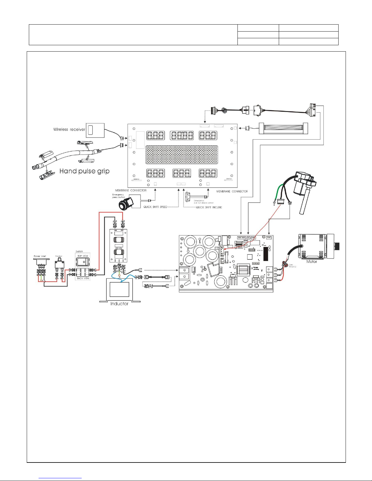
1.Information For Components & System
1.1.System wiring diagram:
Page 4
Document NO. M-7001A-EM-English
PAGE Page 4 of 18
Engineer Manual-Trouble Shooting
VERSION C
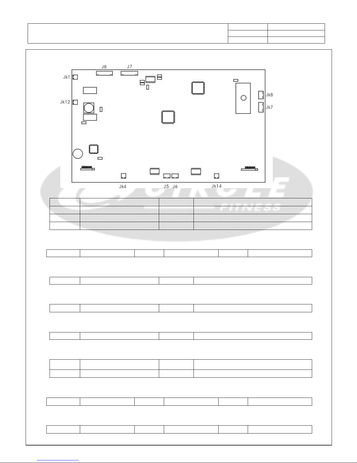
1.2.Console PCB
Console communication wire
Console communication wireConsole communication wire
Console communication wire (
( (
(J7)
P1
(RS485)DX+ / TXD(RS232)
P5 12V
P2
(RS485)DX- / RXD(RS232)
P6 G12(GND)
P3
EXG
P7 SAFETY KEY
P4
WK_UP
Wireless receiver (Jk8)
P1 sensor input P2 VCC P3 GND
SAFE KEY (Jk4)
P1 Driver EN P2 VDD
STOP key(Jk14)
P1
KeyBoard (
S5)
P2
KeyBoard (
D2)
FAN (Jk1)
P1 PWM 0~12V P2 VDD
Hand Pulse (Jk7)
P1
Left reference electrode
P3
Right signal electrode
P2
Left signal electrode
P4
Right reference electrode
Quick shift - SPEED (J5)
P1
SPD +
P2
COM
P3
SPD -
Quick shift - INCLINE (J6)
P1
INC+
P2
COM
P3
INC-
Page 5
Document NO. M-7001A-EM-English
PAGE Page 5 of 18
Engineer Manual-Trouble Shooting
VERSION C
MEMBRANE (KEYBOARD L)
Left (10P)
1(S1) 2(S2) 3(S3) 4(S4) 5(S5)
6(D1)
Target Strength 1 6 Reset/Clear
7(D2)
Rolling Interval 2 7 X
8(D3)
Valley Random 3 8 X
9(D4)
Fat Burn Fitness Test 4 9 X
10(D5)
Ramp H.R.C 5 0 Enter
MEMBRANE (KEYBOARD R)
Right (8P)
1(S6) 2(S7) 3(S8) 4(S9)
5(D6)
Inc 8 Spd 4 Cool Down Inc Up
6(D7)
Inc 6 Spd 6 Fan Inc Down
7(D8)
Inc 4 Spd 8 Stop Spd -
8(D9)
Inc 2 Spd 10 Start Spd +
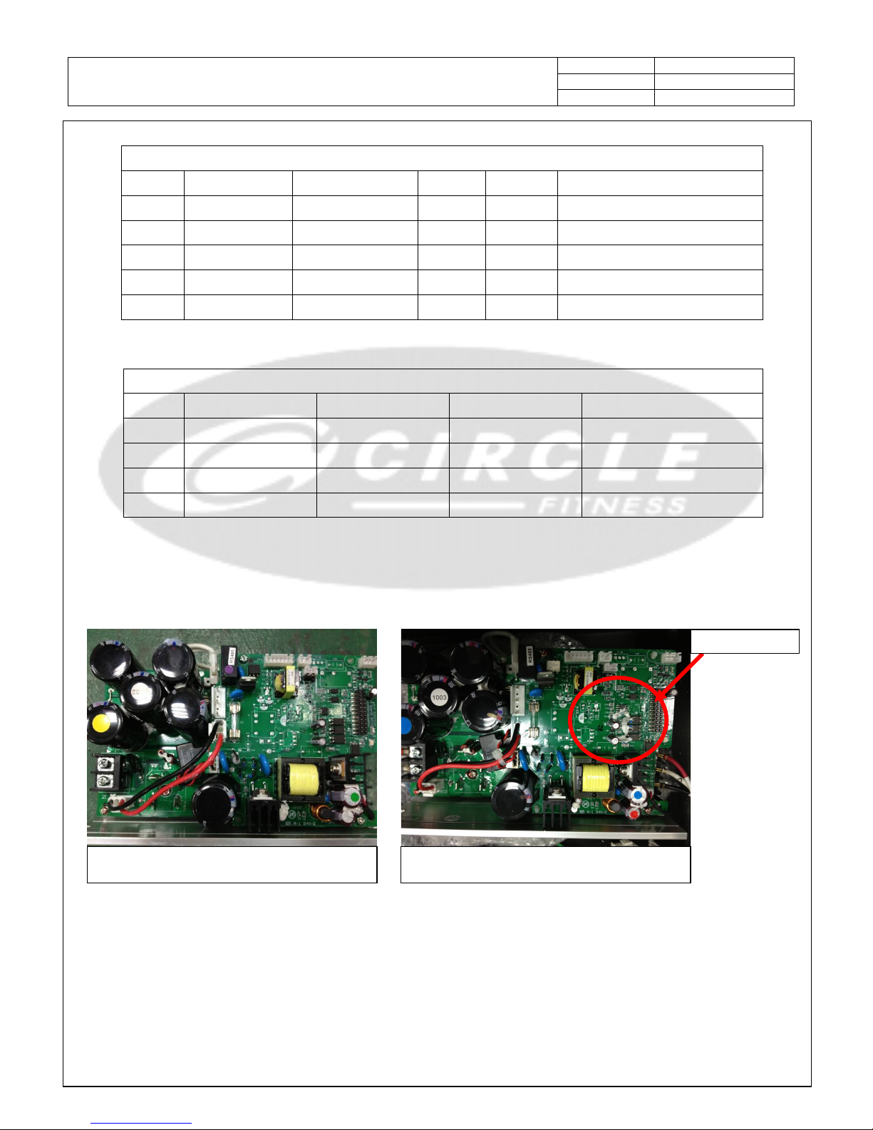
1.3.Inverter
※ Please replace to new version inverter if it is a old version one.
Old version inverter New version inverter
With resistors
Page 6

Document NO. M-7001A-EM-English
PAGE Page 6 of 18
Engineer Manual-Trouble Shooting
VERSION C
2.Error Signal Check And Solutions
2.1.Error message『LE1』:The voltage is too low during exercising, please check the input
AC power source, AC power source voltage shall between 110 / 220 V ± 10%.
2.2.Error message『OC』:The inverter output current overload(over 17.6A), replace inverter
if after reset power then start again still show『OC』. Replace the running belt or
deck if always happen while running.
2.3.Error message『OE』:The operation voltage too high, maybe happen at high incline level
and heavy load exercising, contact manufacture for solution.
2.4.Error message『PrEr』:The inverter Flash memory problem, replace the inverter.
2.5.Error message『EEr』:The inverter EEPROM problem, replace the inverter.
2.6.Error message『LE』:The voltage is too low when in idle or setting mode, please check
the input AC power source. The input AC power source under 110V(220V system) / 65V(110V
system) will show『LE』.
2.7.Error message『9F』:Output power U-V-W inequality, check motor wire connect to inverter
certainly or replace motor.
Page 7

Document NO. M-7001A-EM-English
PAGE Page 7 of 18
Engineer Manual-Trouble Shooting
VERSION C
2.8.Error message『OH』:The inverter over heat, wait for cooling down can re-start, but
it means the loading already too high, have to lubricate or replace running belt or
deck.
2.9.Error message『OL』:The motor current overload(over 110% few minutes), have to replace
the running belt or deck.
2.10. Error message『OL1』:The motor current overload(over 150%), have to replace the
running belt or deck.
2.11. Error message『ntcF』:The thermo sensor abnormal, replace inverter.
2.12. Error message『LF』:The motor wires did not connect well.
2.13. Error message『dbuP』:The inverter dynamic brake system damaged, replace inverter.
2.14. Error message『Err7』:The incline motor position parameter over max or min limit,
check the incline motor connect to inverter certainly show as below. If connection well,
replace inverter and update the console program version to the newest version.(great
than V1.06)
Page 8

Document NO. M-7001A-EM-English
PAGE Page 8 of 18
Engineer Manual-Trouble Shooting
VERSION C
2.15. Error message『Err6』:Incline motor can not reach set position over 42 seconds
Show Err6
Reset power
OFF
ON
Does incline motor moving?
Yes
No
Incline motor jammed, to eliminate jam problem then check
the inverter shall be the new version (refer to 1.3.)
and console firmware version great than V1.05,
if not,
replace or update it.
Is it move about 1~2 then stop
?
Yes
No
Press Start then set incline
to 15.
System operating normal but please check
the inverter
shall be the new version and console firmware version
great than V1.05, if not, replace or update it.
Replace incline motor and check
the inverter
shall be the new version (refer to 1.3.) and
console firmware version great than V1.05,
if not, replace or update it.
Page 9

Document NO. M-7001A-EM-English
PAGE Page 9 of 18
Engineer Manual-Trouble Shooting
VERSION C
2.16. Error message『ESP』:Inverter emergency protection.
Show ESP
Open motor cover.
Dis-connect ESP wire from inverter.
Short circuit the ESP terminal with a screw(Metal).
Reset AC power and wait 5 seconds
Is it still show ESP?
Yes
Replace inverter
No
Replace console
communication wire.
Page 10

Document NO. M-7001A-EM-English
PAGE Page 10 of 18
Engineer Manual-Trouble Shooting
VERSION C
2.17. Error message『UArt』:Communication time out, console can not communication with
inverter over 10 seconds.
`
Open motor cover.
Switch ON the power
Does communication lamp where on the inverter flash before console
show UArt?
Flash No Flash
Replace inverter
Replace console or
communication wire.
Page 11

Document NO. M-7001A-EM-English
PAGE Page 11 of 18
Engineer Manual-Trouble Shooting
VERSION C
2.18. Error message『Err1』:Inverter no output after start.
Show Err1
Reset power
OFF
ON
Does the console show
『UArt』
after 10 seconds?
Yes
Refer to 2.13. error
message
『UArt』
No
Press START to quick start.
Motor did not move then show
Err1?
Yes
Replace inverter to newest version
(refer to 1.3.) and update the console
firmware version to the newest
version.(great than V1.05)
No
Set incline to level 15 th
en set to
level 0.
Does the incline work abnormal
and stop then show
Err1?
Yes
No
System operating normal but please check
the inverter shall be the new version
and console firmware version great
than V1.05, if not, replace or update
it.
The incline motor jammed or input power too low, the input
power shall over 90V(110V system)/200V(220V system).
After to
eliminate
incline motor jammed and input power
problem, please check the inverter shall be the new
version (refer to 1.3.) and console firmware version
great than V1.05, if not, replace or update it.
Page 12

Document NO. M-7001A-EM-English
PAGE Page 12 of 18
Engineer Manual-Trouble Shooting
VERSION C
3.Other Information
3.1.Console no power(No any display)
3.2.Distance window shown『Err』only, no any error message show on time window:To check
the motor wires connection or replace inverter.
3.3.Console work normally but motor can not move:To check the motor wires connection (same
as upon) or replace inverter.
Does lamp lights up on
inverter?
Console no power
Open motor cover.
Yes
No
Replace inverter
Replace console
Check motor wires
connection.
Page 13

Document NO. M-7001A-EM-English
PAGE Page 13 of 18
Engineer Manual-Trouble Shooting
VERSION C
3.4.Incline window show『Err』, incline lose function but other functions normal:
Press and hold『STOP』then press『START』3
seconds to enter engineer mode
Reset power
OFF
ON
Press『Enter』till dot-matrix show『IO』.
Press『incline up』to drive incline motor.
Does incline motor move?
Yes
No
Incline motor jammed, have to eliminate
and try again.
Is parameter can be increase up over 700 when motor
move up?(Press incline up again to stop the incline
motor while parameter over 700)
Yes
System operating normal
No
Replace incline
motor
No
Replace inverter
Page 14

Document NO. M-7001A-EM-English
PAGE Page 14 of 18
Engineer Manual-Trouble Shooting
VERSION C
4.Engineering Mode
4.1.Engineering mode 1: Test mode
4.1.1.Press and hold『Stop』key then press『Start』3 seconds to enter the engineering
mode while in idle mode. The display will show software version, press『Enter』
to begin the test mode.
4.1.1.1. All display will flash together, press『Enter』to next test mode.
4.1.1.2. LED scan mode:this is for production test mode, press『Enter』to next
test mode.
4.1.1.3. LED pilot lamp scan mode:this is for production test mode, press『Enter』
to next test mode.
4.1.1.4. Keys test mode:dot-matrix show【KEY】, each key has their own code when
press a key, the code show as below, press『Enter』to next test mode.
4.1.1.5. Test mode:Press Start can drive motor, press speed keys to change speed,
press incline keys to drive incline motor, press『Enter』back to 4.1.1.1. retest,
press and hold『RESET/CLEAR』then press『Quick Start』3 seconds to exit.
Key Code Key Code Key Code Key Code
Target 001
Reset/clear
011 0
021 Spd-10 031
Rolling 002 1 012 Enter 022 Inc-up 032
Valley 003 2 013 Inc-8 023 Inc-down 033
Fat burn 004 3 014 Inc-6 024 Stop 034
Ramp 005 4 015 Inc-4 025 Fan 035
strength 006 5 016 Inc-2 026 Start 036
interval 007 6 017 Cool down 027 Spd-slow 037
Random 008 7 018 Spd-4 028 Spd-fast 038
Fitness test
009 8 019 Spd-6 029
H.R.C 010 9 020 Spd-8 030
Page 15

Document NO. M-7001A-EM-English
PAGE Page 15 of 18
Engineer Manual-Trouble Shooting
VERSION C
4.2.Engineering mode 2: Factory settings
4.2.1.Press and hold『Stop』key then press『Fast』3 seconds to enter the engineering
mode while in idle mode.
4.2.1.1. Software version:Dot-matrix show【VER】, time window show software version,
press『Enter』to next setting.
4.2.1.2. SET LANGUAGE:Dot-matrix show【SET LANGUAGE】one time then show『ENGLISH』,
press▲ or ▼ change to『NEDERLANDS
NEDERLANDSNEDERLANDS
NEDERLANDS』or 『FRANCAIS
FRANCAISFRANCAIS
FRANCAIS』or 『DEUTSCH
DEUTSCHDEUTSCH
DEUTSCH』or 『ITALIANO
ITALIANOITALIANO
ITALIANO』
or 『ESPANOL
ESPANOLESPANOL
ESPANOL』, press『ENTER』to next setting.(This function only for software
version great than 1.09(include))
4.2.1.3. SET UNIT:Dot-matrix show【SET UNIT】one time then show『METRIC
METRICMETRIC
METRIC』, press
▲ or ▼ change to【ENGLISH
ENGLISHENGLISH
ENGLISH】, press『ENTER』to next setting.
4.2.1.4. FAN SETTING:Dot-matrix show【FAN SETTING】one time then show『ON
ONON
ON』, press
▲ or ▼ change to【OFF
OFFOFF
OFF】, press『ENTER』to next setting.
4.2.1.5. MIN SPEED:Dot-matrix show【SET MIN SPEED THEN PRESS ENTER】, SPEED window
show value, press▲ or ▼ to set value, press『ENTER』to next setting.
4.2.1.6. MAX ELEVATION:Dot-matrix show【SET MAX ELEVATION THEN PRESS ENTER】,
INCLINE window show value, press▲ or ▼ to set value, press『ENTER』to next
setting.
4.2.1.7. Total used distance:Dot-matrix show【ODO】, DISTANCE & TIME window show
total used distance. Total used distance= TIME window value + (DISTANCE window
value X 10000) , press『Reset/Clear』+『Enter』5 seconds can erase total used
distance value, press『ENTER』to next setting.
4.2.1.8. Total used hours:Dot-matrix show【HRS】, TIME window show total hours
value, press『Reset/Clear』+『Enter』5 seconds can erase total used hours value,
press『Enter』back to idle mode.
Page 16

Document NO. M-7001A-EM-English
PAGE Page 16 of 18
Engineer Manual-Trouble Shooting
VERSION C
5.Inverter Information and External Control
5.1.External control Key Pad usage:
5.1.1.External control Key Pad appearance(KP-208)and connection.
5.1.2.Monitor mode and operation:
Output frequency
Frequency setting Output voltage
PN Voltage
Output current
void
void void Incline setting
void
void
Page 17

Document NO. M-7001A-EM-English
PAGE Page 17 of 18
Engineer Manual-Trouble Shooting
VERSION C
5.1.3.To control inverter by External control Key Pad:
5.1.3.1. Start / Stop / Fast / Slow
Start
Stop
Fast
Slow
Press PROG
change to function setting at any
display mode, press ▲ ▼ to show F_001.
Press FUN/DATA enter the F_001 setting,
default value is【0】.
Press ▲ change value to【1】.
Press FUN/DATA to save and exit.
Page 18

Document NO. M-7001A-EM-English
PAGE Page 18 of 18
Engineer Manual-Trouble Shooting
VERSION C
5.1.3.2. Incline control:
………
Parameter setting Incline parameter
Incline UP
Incline Down
Monitor mode
Monitor mode 9
 Loading...