

Page 1

0
Page 2

1
Thank you for your purchase of a NAUTICAM camera housing.
At NAUTICAM, we pride ourselves on the ability to recognise the
requirements of professional as well as amateur underwater
photographers and fulfill them through the innovative designs of our
products. We strive to achieve a high level of user-friendliness by
allowing stress-free installation and easy operation of all important
functions of the camera.
Each housing is individually inspected and water pressure tested to
ensure optimum quality.
Please read this manual carefully before using the housing, this will
maximise its performance as well as its lifetime.
Page 3

2
1. All NAUTICAM Products are warranted against any material and
manufacturing defects for one year from the date of purchase for
consumer use.
2. NAUTICAM accepts no liability for any damage to and defects in the
housing caused by improper use and/or poor maintenance; it is the
responsibility of the owner to carefully follow the instructions in
this manual.
3. NAUTICAM does not hold responsibility for damage, of any nature,
to any equipment used with and/or placed within the housing.
4. NAUTICAM accepts no liability for any loss of captured images or
the inability to capture images even if it is due to the
malfunctioning or leakage of the housing.
5. This warranty only applies to products purchased from authorised
NAUTICAM dealers and does not extend beyond the original retail
purchaser.
6. Unauthorised modifications and/or repairs of the housing will
automatically invalidate this warranty.
7. To return products for service, please contact our regional
distributor, normally you would need to notify them by email first
and ship them the product by registered mail, along with your
contact details and a brief description of the defect.
Page 4

3
1. NA-GX7 housing
2. Instruction manual
3. Spare silicone rubber housing o-ring
4. O-ring remover
5. CR2450 battery (for moisture alarm)
6. Lubricant
7. Set of Allen keys
Spare silicone rubber o-ring
Lubricant
Set of Allen keys
CR2450 battery
O-ring remover
Page 5

4
1. A water-tight test without the camera inside the housing is highly
recommended when using the system for the first time and after
the changing of port and O-ring(s).
2. Do not use lubricants from other brands with the silicone rubber O-
ring on this housing, only use the lubricant provided by NAUTICAM.
3. Discontinue use immediately should you notice any leakage.
4. Store the housing in a robust, shock-proof container during
transportation; avoid transporting with any equipment, such as a
camera, inside the housing.
5. When travelling by air, do not close the housing if the port is
installed, as this may lead to a pressure difference between the
atmosphere and inside the housing.
6. Care must be taken when opening the housing, as pressure may
build up inside the housing which increases the opening force.
7. Do not open the product in a wet or sandy environment. Protect
the interior from moisture and debris in order to prevent
malfunction or leakage.
8. Do not store the product in an environment of high humidity.
9. Do not leave the housing and the camera in direct sunlight for
prolonged periods.
10. Keep out of reach of children, failure to do so could result in injury.
11. Defective products should be shipped to our distributors for service,
unauthorized disassembling and/or modifications could result in
malfunction or leakage.
Page 6

5
Specifications 6
Identification of Parts 7
Preparation of the Housing 10
Opening and Locking the Housing 13
Installing the Camera 14
Mounting the Port 16
Care and Maintenance 18
Optional Accessories
19
Page 7

6
Construction
Housing body: Aluminium alloy
Surface treatment: Hard anodised
Display window: Abrasion resistant polycarbonate
Dimensions
Width: 193mm
Height: 128mm
Depth: 99mm
Weight Approx. 1.08kg (without camera)
Buoyancy Slightly negative
Depth rating 100 metres
Features
Moisture alarm: Blinking LED and audible alarm
TTL capability:
Optical fibre mount included for
external strobes connection,
utilising the camera’s pop-up flash
as trigger.
Port mount:
Patented easy port installation
system.
Control dial: Easily reached by thumb.
Flash up/off lever:
Allows the camera's built-in flash
to be disabled underwater.
Page 8

7
1 Accessory coldshoe 6 Zoom/Focus knob
2 Optical fibre mount 7 Port release safety button
3 Port alignment index 8 Port lock/release lever
4 M10 strobe mounting base 9 Lens release button
5 M16 accessory port
1
2
3
4
7
6
9
5
8
Page 9

8
10 Flash up/off lever 15 Mode dial
11 Rear dial 16 Front dial
12 Housing lock safety button 17 Shutter release lever
13 Housing lock 18 1/4”–20UNC tripod socket x 2*
14 ON/OFF switch
10
11
16
17
18
15
14
* The maximum length of screws that can be
used with the tripod sockets is 4mm
12
13
Page 10

9
19 LVF/ FN4 button 27 Playback button
20 Moisture alarm window 28 Up selection/ISO button
21 Motion picture button 29 Left selection/AF Mode button
22 Focus mode lever 30 Right selection/WB button
23
Rear control wheel control
button
31 MENU/ SET button
24 AF/AE lock button 32
Down selection/Drive Mode
button
25 Q.MENU/ Fn1 button 33 Wi-Fi/ Fn3 button
26 Display button 34 Delete/Cancel/ Fn2 button
19
21
22
23
24
25
27
26
20
28
29
31
30
32
33
34
Page 11

10
1. After verifying that the housing O-ring is in good condition, lightly
coat it with the lubricant provided.
2. Make sure the O-ring groove located in the rear part of the housing
is free from any foreign material; the groove can be cleaned with
the aid of a microfiber cloth.
3. Place the O-ring into the groove.
4. To install the optical fibre mount for external strobe connection,
fasten it with the screws provided to the threaded sockets of the
accessory coldshoe as shown:
Page 12

11
1. Install the CR
2450
battery provided
into the battery compartment
inside the rear housing. Then switch
on the alarm.
To rem
ove the battery, use a small
flat-head screwdriver to lift up the
battery as shown.
5. Setting up the moisture alarm:
3. Test the alarm by contacting the two
wires near the bottom of the
housing with a damped cotton bud;
the alarm should start giving out a
repeating “beep” sound along with
a flashing red light. The “beep”
sound and the light should keep on
going for 5 seconds after the
removal of the damped cotton bud.
2. Switch on the alarm. The LED light
will turn blue for five seconds
indicating the battery is normal.
Then it goes into flashing blue light
standby mode.
Page 13

12
LED status identification:
On start up:
LED indicator
Status
Steady "Blue" light
Battery is normal,
goes into flashing "Blue" light
standby mode after 5 seconds.
"Blue" and "Red"
lights alternating
Battery low. R
eplac
e battery
as soon as possible
.
Goes into standby mode after 5 seconds.
Steady "Red" ligh
t Battery empty
, replace battery.
After start up:
LED indicator
Status
Flashing "Blue"
light
Standby mode. The moisture alarm is active, and
the system is ready for vacuum indication
whenever a vacuum is detected.
Flashing "Red" light
with audio sounds.
Moisture is de
tected.
Flashing "Yellow"
light
Some vacuum is detected,
target vacuum level is
not reached.
Steady "Green"
light
Target vacuum level is reached.
Rapidly flash
"Yellow" light
Vacuum is dropping. (Will occur only after target
vacuum level is reached)
R
apidly flashing
"Red" light
Vacuum is totally lost. Circuit stalled until switched
off. (Will occur only after target vacuum level is
reached)
(Optional) Vacuum valve can be
attached to the housing via one
of the accessory port for
conducting a vacuum seal test.
Please refer to the manual of the
vacuum valve for more details of
the operation.
Page 14
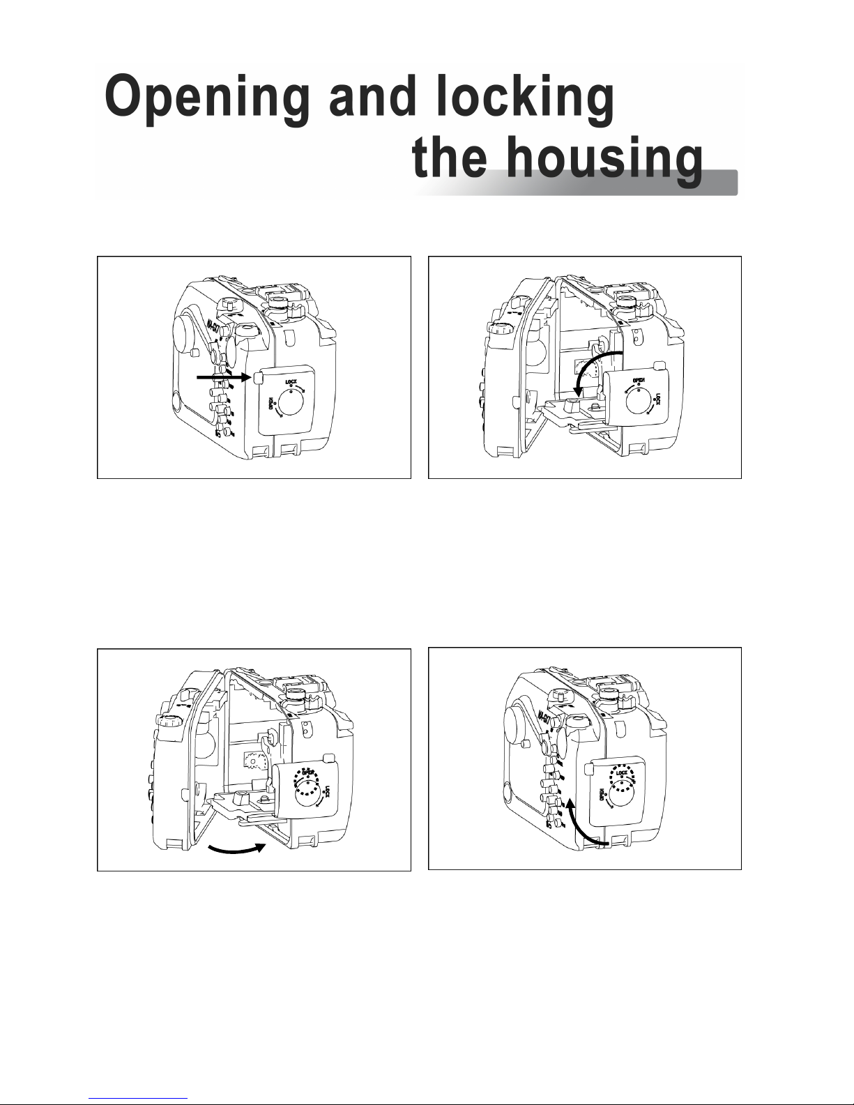
13
To open the housing:
To lock the housing:
2. Turn the
housing lock anti
-
clockwise for 270°, until the lock
reaches the “Open” position as
shown.
3. Close the housing while the
housing lock is in the “Open”
position.
4. Turn the housing lock clockwise
for 270°, until the lock reaches the
“lock” position as shown.
Confirm that the white indicator
line on the safety button is visible.
1. Press the housing lock safety
button.
Page 15
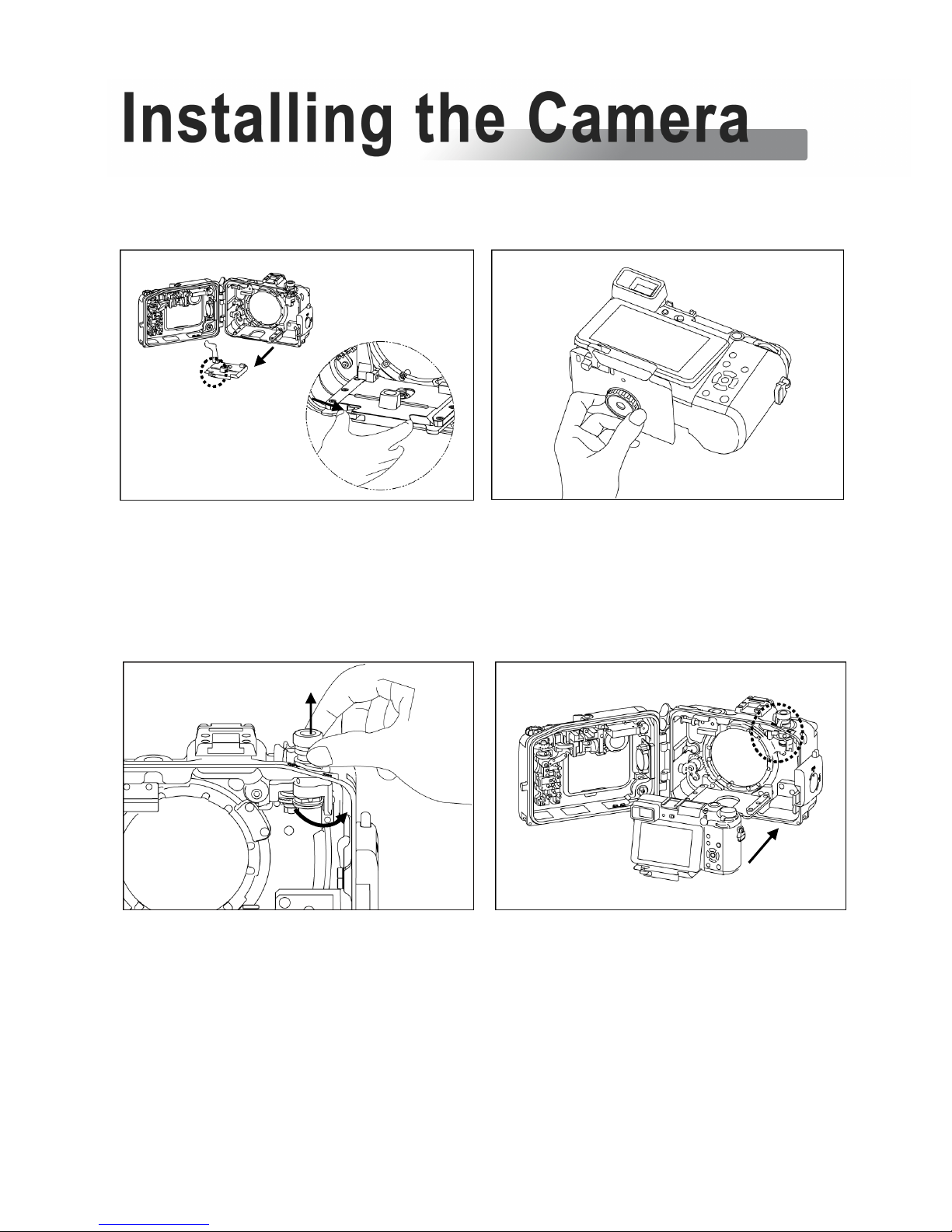
14
1. Disengage the
red
camera saddle
lock by pressing it inwards.
Remove the camera saddle from
the housing by sliding it outwards
2. Tilt the LCD monitor of the camer
a
upwards, then attach the saddle to
the camera by tightening the screw
to the tripod socket of the camera.
3. Lift the Mode dial/ON/OFF dial
upwards and turn it to the
side.
4. Install
the camera by sliding the
attached saddle along the rail in
the housing until it cannot go in
any further.
*Make sure the Mode dial/
ON/OF dial do not block in the
way (step 3).
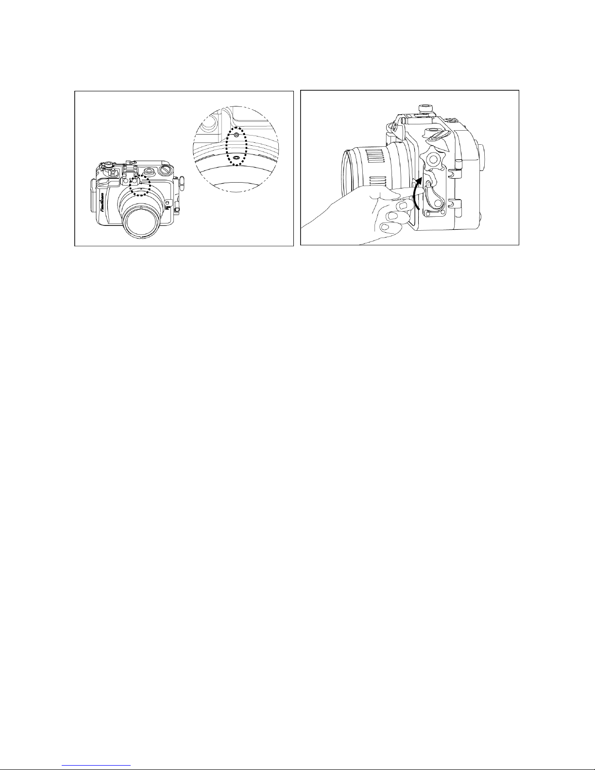
Page 16

15
5. Gently push the Mode dial/ON/OFF
dial downwards ensuring the
actuator correctly engages with
the ON/OFF lever of the camera.
6. For removal of the camera from
the housing, reverse the above
procedures.
Page 17

16
Please refer to the NAUTICAM system port chart for a range of compatible
ports.
1. Remove the O
-
ring from the
port, inspect for any damage
and lightly coat it with the
provided lubricant before
placing it back into its groove.
2. Verify that the port opening of
the housing is clean and free
from foreign material.
3. Push the safety button of the port
locking lever downwards.
4. Turn the port locking lever to the
release position as shown.
5. Lift housing cap.
Page 18
17
6. Align the Port mounting indices of
the port and the housing.
7. Gently push the port into the port
opening of the housing, until it
cannot go in any further.
8. Lock the port into place by turning
the port locking lever to the inward
position. To ensure that the port is
securely mounted, confirm that the
green line on the safety button of
the port locking lever is visible.
9. To remove the port from the
housing, simply turn the port locking
lever to the outward position and
gently pull it out.
Page 19

18
1. Soak the housing system in fresh water after each salt water use,
during which all control buttons/knobs should be operated a few
times to avoid the accumulation of salt residue; wipe the housing
with a towel before opening.
2. After each day of diving, it is advisable to have the main O-ring in
the rear part of the housing removed from its groove with the Oring remover and inspected for damage. Also check that the O-ring
retains its original circular shape; never stretch the O-ring
excessively or remove it with a sharp object. The O-ring groove
should be cleaned to ensure it is free from any salt deposit or
foreign material; lightly coat the O-ring with the provided lubricant
before reinstalling it in the groove. A damaged O-ring should be
discarded immediately and replaced only with one that is provided
by NAUTICAM.
3. Replace the main O-ring annually.
4. It is recommended that you ship the housing to our distributor for a
complete overhaul every year or after every 200 dives.
Page 20
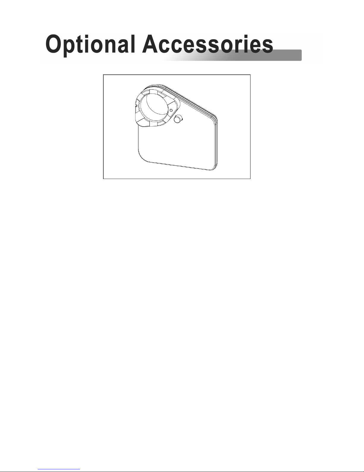
19
P.N.
1775
2
NA-GX7 LCD window for Nauticam enhanced viewfinders
Page 21

20
 Loading...