


0

1
Thank you for your purchase of a NAUTICAM digital camera housing.
At NAUTICAM, we pride ourselves on the ability to recognise the requirements of
professional as well as amateur underwater photographers and fulfill them
through the innovative designs of our products. We strive to achieve a high level
of user-friendliness by allowing stress-free installation and easy operation of all
important functions of the camera.
Each housing is individually inspected and water pressure tested to ensure
optimum quality.
Please read this manual carefully before using the housing, this will maximise its
performance as well as its lifetime.

2
1. All NAUTICAM Products are warranted against any material and manufacturing
defects for one year from the date of purchase for consumer use.
2. NAUTICAM accepts no liability for any damage to and defects in the housing
caused by improper use and/or poor maintenance; it is the responsibility of the
owner to carefully follow the instructions in this manual.
3. NAUTICAM does not hold responsibility for damage, of any nature, to any
equipment used with and/or placed within the housing.
4. NAUTICAM accepts no liability for any loss of captured images or the inability
to capture images even if it is due to the malfunctioning or leakage of the
housing.
5. This warranty only applies to products purchased from authorised NAUTICAM
dealers and does not extend beyond the original retail purchaser.
6. Unauthorised modifications and/or repairs of the housing will automatically
invalidate this warranty.
7. To return products for service, please contact our regional distributor,
normally you would need to notify them by email first and ship them the
product by registered mail, along with your contact details and a brief
description of the defect.

3
1. NA-D7000v housing
2. Instruction manual
3. Spare silicone rubber main o-ring
4. O-ring remover
5. CR2032 battery (for moisture alarm)
6. Lubricant
7. Set of Allen keys
Spare silicone rubber o-ring
Lubricant
Set of Allen keys
CR2032 battery
O-ring remover

4
1. A water-tight test without the camera inside the housing is highly
recommended when using the system for the first time and after the changing
of port and O-ring(s).
2. Do not use lubricants from other brands with the silicone rubber O-ring on this
housing, only use the lubricant provided by NAUTICAM.
3. Discontinue use immediately should you notice any leakage.
4. Store the housing in a robust, shock-proof container during transportation;
avoid transporting with any equipment, such as a camera, inside the housing.
5. When travelling by air, do not close the housing if the port is installed, as this
may lead to a pressure difference between the atmosphere and inside the
housing.
6. Care must be taken when opening the housing, as pressure may build up inside
the housing which increases the opening force.
7. Do not open the product in a wet or sandy environment. Protect the interior
from moisture and debris in order to prevent malfunction or leakage.
8. Do not store the product in an environment of high humidity.
9. Do not leave the housing and the camera in direct sunlight for prolonged
periods.
10. Keep out of reach of children, failure to do so could result in injury.
11. Defective products should be shipped to our distributors for service,
unauthorized disassembling and/or modifications could result in malfunction
or leakage.

5
Specifications
6
Identification of Parts
7
Preparation of the Housing
12
Opening and Closing the Housing
15
Installing the Camera
16
Flash Operation
19
Mounting the Port
20
Connecting the Strobe System
22
Changing the Viewfinder
26
Care and Maintenance
28

6
Construction
Housing body:
Aluminium alloy
Surface treatment:
Hard anodised
Display window:
Abrasion resistant polycarbonate
Grip handles:
Polycarbonate and rubber
Dimensions
(with handles)
Width:
326 mm
Height:
172 mm
Depth:
125 mm
Weight
2.55 kg (without camera)
Buoyancy
Slightly negative
Depth rating
100 metres
Features
Moisture alarm:
Blinking LED and audible alarm
Viewfinder:
0.66X viewfinder
TTL capability:
Single Nikonos 5-pin bulkhead (optional)
2 optical bulkheads utilising on camera
pop-up flash as commmander
Port mount:
Patented port locking lever for easy port
installation.
Exposure
compensation lever
Allows easy exposure adjustments from
the right handle.
Flash up/off lever:
Allows the camera’s built-in flash to be
disabled underwater.
Live view
lever/Movie record
button
Specially designed for the easy operation
of the movie recording.

7
1
On/Off control knob
8
Metering button
2
Grip handle x 2
9
Live view lever
3
Port lock/release lever
10
Shutter release lever
4
Optical bulkhead for strobe
connections x 2
11
Exposure compensation lever
5
Port alignment index
12
Sub-command knob
6
Flash up/off lever
7
AE-L/AF-L lever
6 7 8 9 10
11
12 5 4 3 1
2
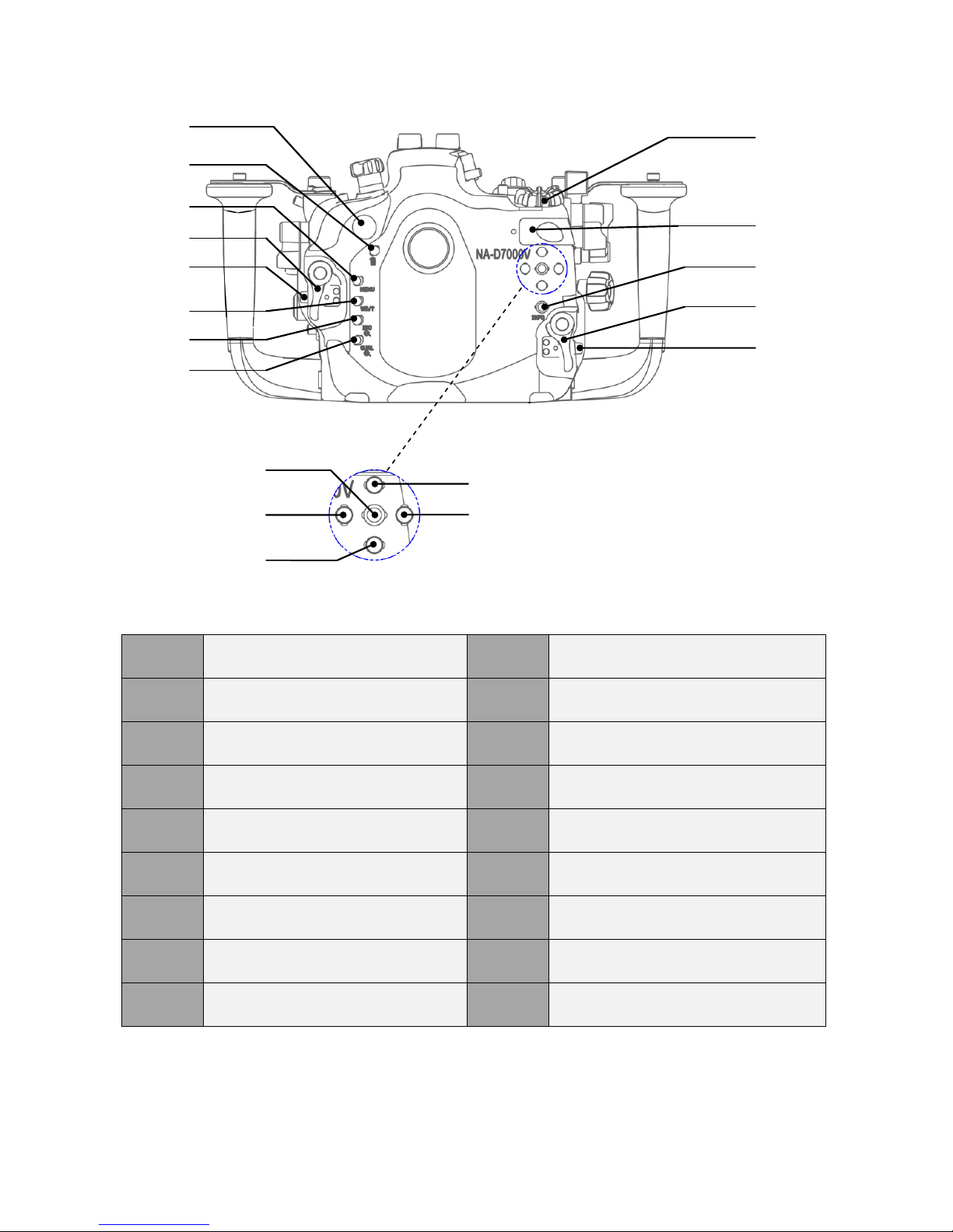
8
14
Moisture alarm window
23
Movie record button
15
Delete button
24
Info button
16
Menu button
25
Housing lock (R)
17
Housing lock (L)
26
Housing lock safety button (R)
18
Housing lock safety button (L)
27
OK button
19
Help/White balance button
28
Left selection button
20
Thumbnail/Playback zoom out
button
29
Down selection button
21
Playback zoom in/Image quality
button
30
Up selection button
22
Main command knob
31
Right selection button
30
31
27
28
29
22
23
24
25
26
14
15
16
17
18
19
20
21

9
32
M16 optional accessory port
38
Playback lever
33
Lens release button
39
Focus mode selection knob
34
Mode knob
40
AF mode button
35
Release mode knob
41
Zoom/focus gear disengagement
lever
36
Release mode dial lock release
button
42
Zoom/focus knob
37
Flash mode/flash compensation
button
34
35
36
37
38
39
40
32
33
41
42

10
Shooting Tips
1. By setting the “Release Button to Use Dial” function of the D7000 camera to
Yes allows adjustments which are normally made by holding down a button
and rotating a command dial to be made by rotating the command dial after
the button is pressed and released.
To enable this function, under Menu, scroll to
Custom Setting Menu (Pencil shaped icon on the
left of the LCD screen), enter ‘f’ Controls.
Then scroll to ‘f7’ Release Button to Use Dial and
enter.
Select ‘Yes’ and press OK.
2. By setting the “LCD illumination” function of the D7000 camera to On, the
top control panel backlight can be turned on by pressing the shutter release
lever halfway while exposure meters are active; the length of time that the
camera continues to meter exposure can be assigned by the “Auto Meter-off
Delay” setting.
To enable the “LCD illumination” function, under
Menu, scroll to Custom Setting Menu, enter ‘D’
Shooting/Display.

11
Then scroll to ‘d10’ LCD illumination and enter.
Select ‘On’ and press OK.
To control the time period of exposure meters,
under Menu, scroll to Custom Setting Menu,
enter ‘c’ Timers/AE lock.
Then scroll to ‘c2’ Auto Meter-off Delay and enter.
Select the preferred time period and press OK.

12
1. After verifying that the main O-ring is in good condition, lightly coat it with the
lubricant provided.
2. Make sure the O-ring groove located in the front part of the housing is free
from any foreign material; the groove can be cleaned with the aid of a
microfiber cloth.
3. Place the main O-ring into the groove by gently pushing it, first at the corners,
then the whole perimeter.
4. If necessary, spacers can be used to increase space between the grip handles
and the housing; please use the longer screws provided to attach the grip
handles and the spacers to the housing.
5. To install the Nikonos 5-pin bulkhead (Optional, M16 to M14 step down adaptor
required):
ii. Install the M16 to M14 step
down adaptor with a spanner.
i. Remove the M16 plug from the
threaded hole with a coin.

13
ii. Insert the 5-pin bulkhead through
the threaded hole.
v. Slide the accessory shoe plug of
the housing into the accessory
shoe of the camera.
iii. Tighten the 5-pin bulkhead with a
spanner.
iv. Connect the 5-pin bulkhead to the
accessory shoe plug.

14
Setting up the moisture alarm
1. Install the CR2032 battery provided
into the battery compartment on
the circuit board inside the rear
part of the housing.
2. Test the alarm by contacting the
two wires near the bottom of the
housing with a damped cotton bud;
the alarm should start giving out a
repeating “beep” sound along with
a flashing red light. The “beep”
sound and the light should keep on
going for 5 seconds after the
removal of the damped cotton bud.

15
1. Always open and close the housing with the front facing down, place the
housing on a flat surface or in your lap.
2. When closing, make sure there is nothing caught between the closing surfaces
of the two halves of the housing.
3. The housing can be opened and closed by operating the two housing locks;
when opening, press the safety buttons, then turn the locks outwards.
4. To close, turn the locks towards the housing, and then make sure they are
locked in place securely.

16
1. Turn the locking lever on the tray
of the housing to the “open”
position.
2. Remove the camera saddle from
the housing.
3. Pull the sliding bar on the saddle
to its outward position.
4. Align the pin on the saddle with
the opening in the bottom of the
camera as indicated in the
diagram.

17
5. Attach the saddle to the camera by
tightening the screw to the tripod
socket of the camera with a
screwdriver or a coin.
7. Disengage the zoom/focus gear
using the zoom/focus gear
disengagement lever.
8. Make sure the camera power is
off and the On/Off control knob
on the housing is in the “off”
position.
9. Mount the camera by sliding the
attached saddle along the rail in
the housing until it cannot go in
any further.
6. After ensuring the C/S/M activator
on the sliding bar matches the
focus mode selector of the
camera, push the sliding bar to its
inward position. Check that by
rotating the activator, the focus
mode of the camera can be
altered.

18
11. Confirm that all the controls of the
housing are correctly engaged.
12. For removal of the camera from the
housing, reverse the above
procedures.
10. Lock the camera into place by
turning the locking lever to the
“lock” position.
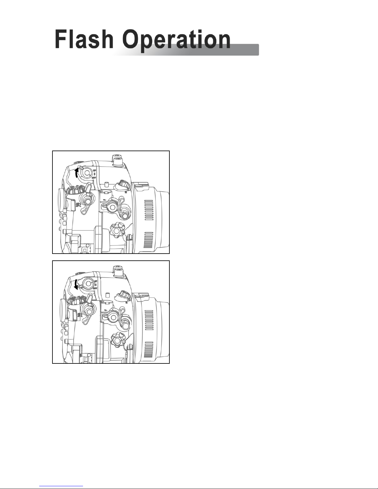
19
The D7000 camera’s built-in flash can be used for triggering external strobes.
To raise the flash after the camera has been installed into the housing, press the Flash
mode/flash compensation button; pressing this button also allows the flash exposure to
be adjusted by the sub-command knob.
To disable the flash, turn the Flash up/off lever to
the “Off” position.
Turn the lever to the “Up” position to enable the
flash again.
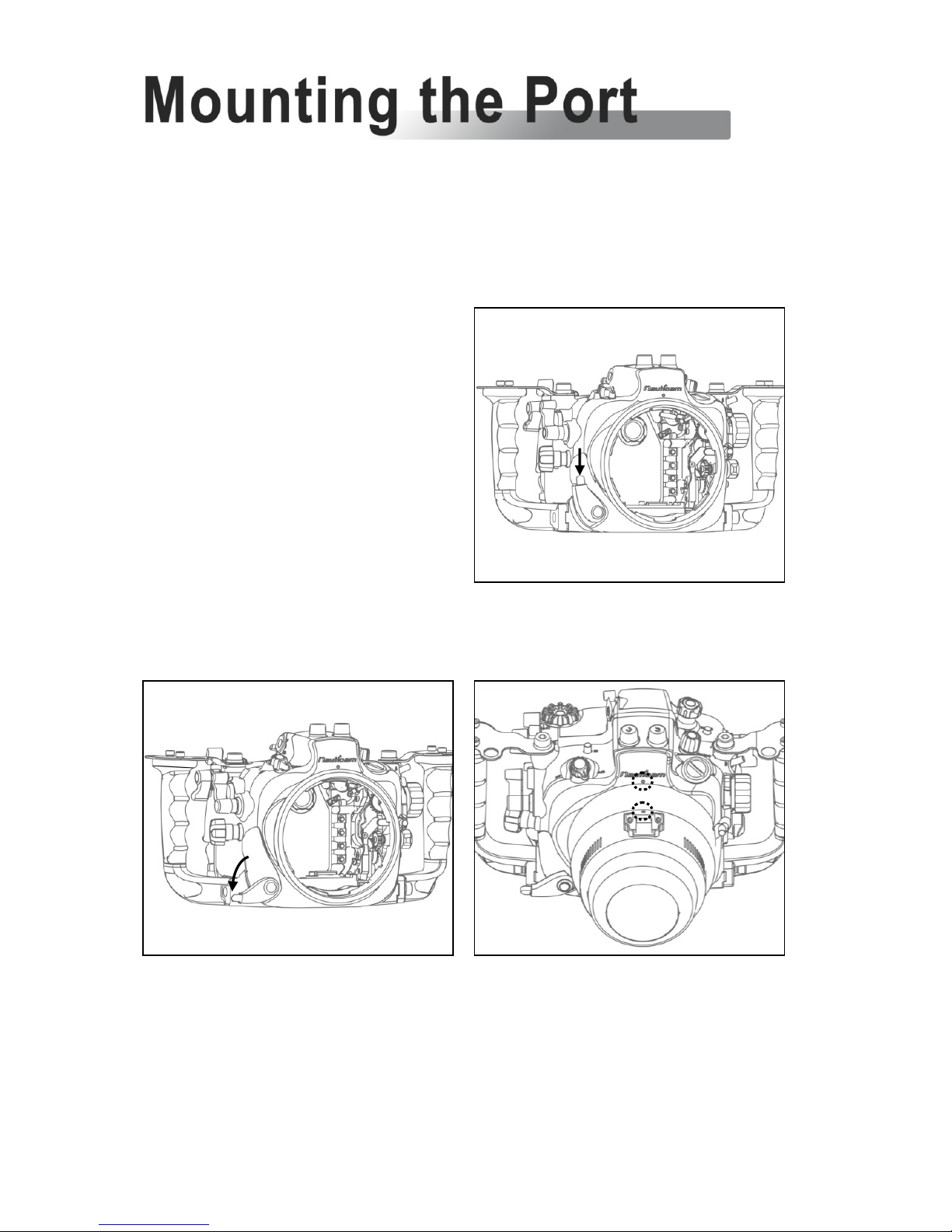
20
Please refer to the NAUTICAM port system chart for a range of compatible
ports; note that extension rings may be needed for certain lenses and adaptors
are available for the attachment of ports of other manufacturers.
1. Remove the O-ring from the port,
inspect for any damage and lightly
coat it with the provided lubricant
before placing it back into its
groove.
2. Verify that the port opening of the
housing is clean and free from
foreign material.
3. Push the safety button of the port
locking lever downwards.
4. Turn the port locking lever to the
outward position.
5. Align the mounting indices of the
port and the housing; these appear
as white circles on both the port and
the housing.
6. Gently push the port into the
opening of the housing, until it
cannot go in any further.
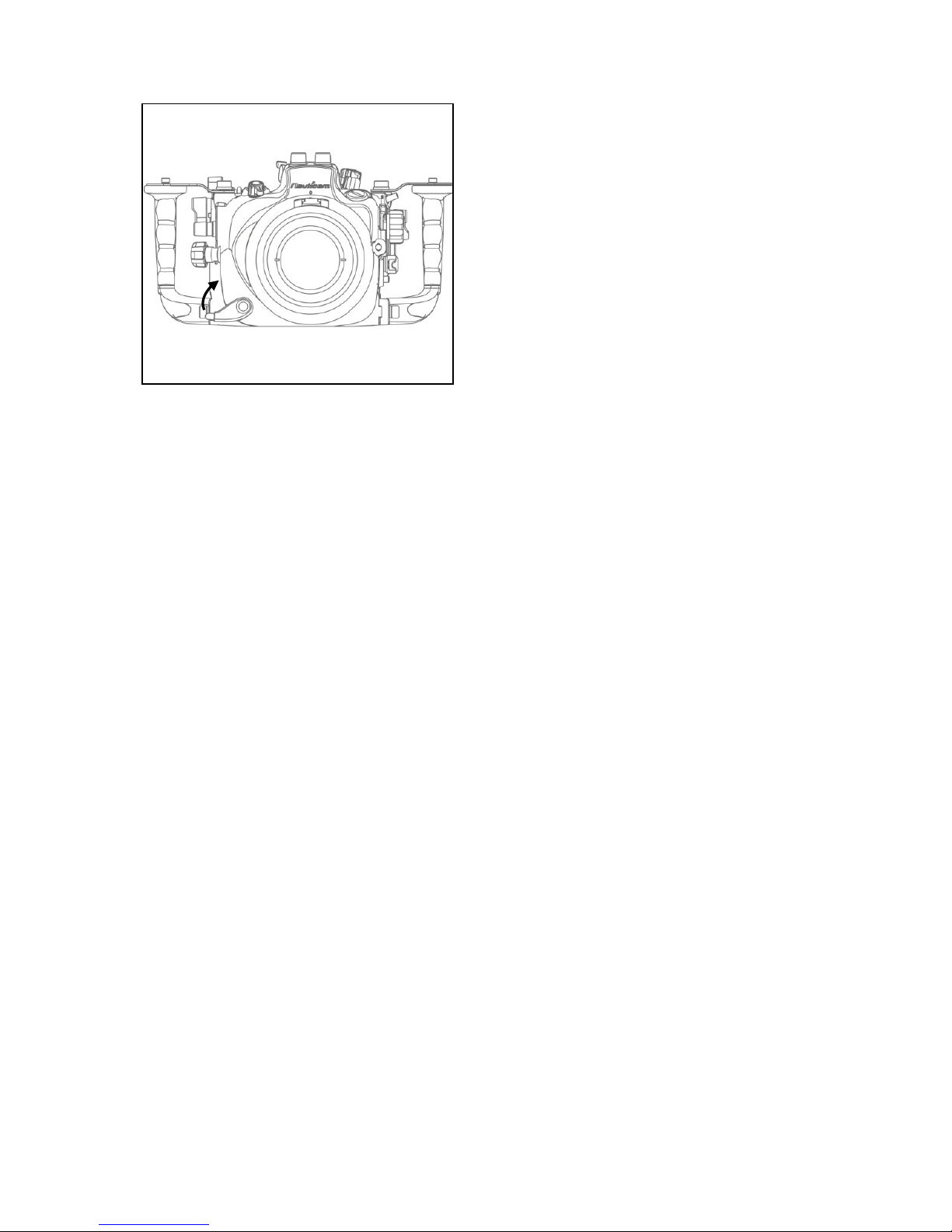
21
7. Lock the port into place by turning
the port locking lever to the inward
position. To ensure that the port is
securely mounted, confirm that the
green line on the safety button of the
port locking lever is visible.
8. To remove the port from the housing,
simply turn the port locking lever to
the outward position and gently pull
it out.
22
Optional strobe attachment balls can be attached to the strobe mounting bases
on the housing or onto the top of the handles.
There are two ways of connecting strobes to the NA-D7000V housing: A) by
optical connection through the Optical Bulkheads; B) by electrical connection
through the Nikonos 5-pins bulkhead.
A) Using the Optical Bulkheads
The built-in pop-up flash of the D7000 camera can be used as a
commander to send out signals (including i-TTL commands) to the
strobes via the 2 Optical Bulkheads. It can be utilised in different ways
depending on the type of strobes connected to the housing:
A1) Nikon i-TTL compatible strobes such as SB-R200, SB-600, SB-800,
SB-900:
These strobes can fully utilise the Nikon i-TTL controls protocols
enabling individual TTL exposure compensation of each of the 2
strobes connected to the Optical Bulkheads. Do ensure that the other
ends of the optical fibres are pointing onto the light sensor window of
the strobes.
To set the D7000 camera to i-TTL
Commander mode, under Menu, scroll to Custom
Setting Menu (Pencil shaped icon on the left of the
LCD screen), enter ‘e’ Bracketing/flash.
23
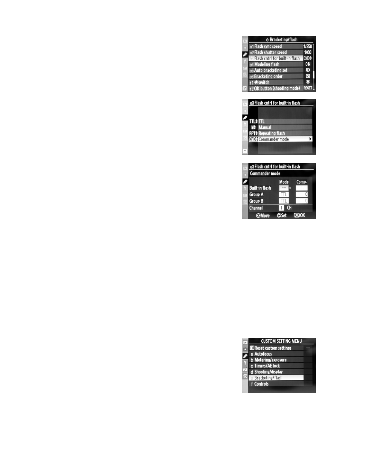
Then scroll to ‘e3’ Flash cntrl for built-in flash and
enter.
Scroll to Commander mode.
Set the Built-in flash Mode to ‘--‘, Group A (one of
the strobes) to Mode ‘TTL’, and Group B (the other
strobe) to Mode ‘TTL’.
The exposure compensation of each strobe can be set individually (A
and/or B) by entering the value under Comp.
Be sure the Channel number selected is the same of the 2 strobes.
A2) Strobes with S-TTL (e.g. Inon z-240) or DS-TTL (e.g. Sea & Sea YS-110α)
capabilities:
We recommend using these strobes in either S-TTL/DS-TTL or manual mode.
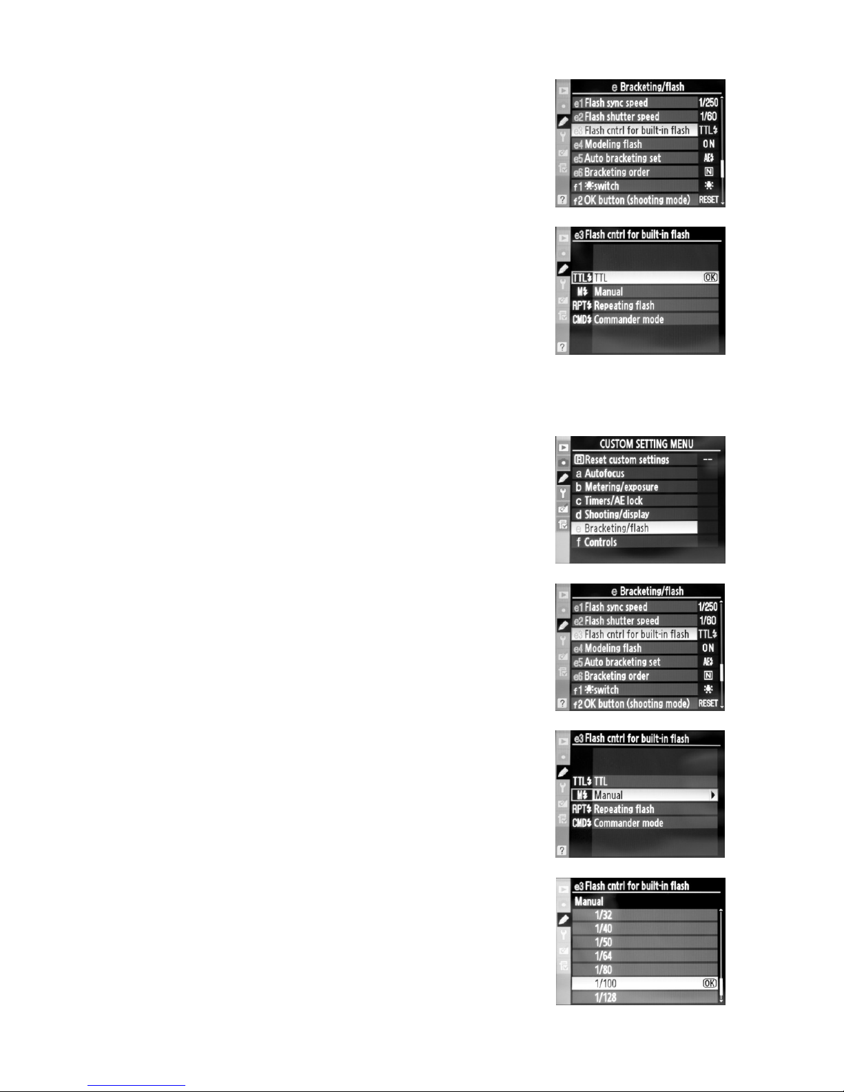
For S-TTL/DS-TTL operation, set the built-in flash of
D7000 camera to TTL mode. From the Menu, scroll
to Custom Setting Menu (Pencil shaped icon on
the left of the LCD screen), enter ‘e’
Bracketing/flash.
24
Then scroll to ‘e3’ Flash cntrl for built-in flash and
enter.
Scroll to TTL and press OK.
For Manual operation, set the built-in flash of the
D7000 camera to Manual mode. From the Menu,
scroll to Custom Setting Menu (Pencil shaped icon
on the left of the LCD screen), enter ‘e’
Bracketing/flash.
Then scroll to ‘e3’ Flash cntrl for built-in flash and
enter.
Scroll to Manual.
A list of power outputs (of the built-in flash) will
appear, selecting a relatively small output (1/100 or
1/128 and press OK) should be adequate to trigger
the Inon strobes while saving the D7000 battery
energy.

25
A3) Other strobes
The optical signal from the D7000 built-in flash can also be utilised to
trigger other strobes having an optical sensor.
B) Using the Nikonos 5-pin bulkhead
The Nikonos 5-pin bulkhead connects to all the 5 contact points of the
D7000 hotshoe for iTTL compatible operation.

26
In order that users can change to a preferred viewfinder easily, the 0.66X
viewfinder which comes with this housing is designed so that it can be removed
and re-installed by following the simple steps described below.
To remove the viewfinder:
1. Remove the retainer O-ring of the
viewfinder inside the rear half of
the housing by making use of the
recess on the viewfinder.
2. Gently push the viewfinder from
the inside of the housing.

27
To re-install the viewfinder:
3. Push the viewfinder from the
outside of the housing until it
cannot go in any further.
4. Place the retainer O-ring of the
viewfinder back from inside the
housing.
1. Lightly coat the O-rings on the
outer periphery of the
viewfinder body with lubricant.
2. Align the viewfinder with the
sleeve in the display window.

28
1. Soak the housing system in fresh water after each salt water use, during which
all control buttons/knobs should be operated a few times to avoid the
accumulation of salt residue; wipe the housing with a towel before opening.
2. After each day of diving, it is advisable to have the main O-ring in the front part
of the housing removed from its groove with the O-ring remover and
inspected for damage. Also check that the O-ring retains its original circular
shape; never stretch the O-ring excessively or remove it with a sharp object.
The O-ring groove should be cleaned to ensure it is free from any salt deposit
or foreign material; lightly coat the O-ring with the provided lubricant before
reinstalling it in the groove. A damaged O-ring should be discarded
immediately and replaced only with one that is provided by NAUTICAM.
3. Replace the main O-ring annually.
4. It is recommended that you ship the housing to our distributor for a complete
overhaul every year or after every 200 dives.

29
 Loading...