


NV30/NV40 Transmitter
Operations and Maintenance
Manual
Document:NHB-NV30-NV40-OPS-3.3
Issue: 3.3 2014-12-10
Status: Standard


Nautel Limited
10089 Peggy’s Cove Road
Hackett’s Cove, NS Canada B3Z 3J4
Phone: +1.902.823.3900 or
Toll Free: +1.877.6NAUTEL (6628835) (Canada & USA only)
Fax: +1.902.823.3183
Nautel Inc.
201 Target Industrial Circle
Bangor, Maine USA 04401
Phone: +1.207.947.8200
Fax: +1.207.947.3693
Customer Service (24 hour support)
+1.877.628.8353 (Canada & USA only)
+1.902.823.5100 (International)
Email: support@nautel.com
Web: www.nautel.com
The comparisons and other information provided in this document
have been prepared in good faith based on publicly available
information. The reader is encouraged to consult the respective
manufacturer's most recent published data for verification.
© Copyright 2014 NAUTEL. All rights reserved.


NV30/NV40 Operations and Maintenance Manual Table of contents
Contents
Release control record vii
Description 1-1
Ac-dc power stage 1-2
Control/monitor stage 1-3
RF drive stage 1-4
RF power stage 1-6
Operating the transmitter 2-1
Using the AUI 2-2
Home page 2-14
Menu page - describing transmitter operations 2-15
Logs page - viewing transmitter log 2-16
Viewing tool menu panels 2-25
Viewing real-time meters 2-40
Presets - editing operational settings 2-44
Viewing transmitter status 2-59
Factory Settings 2-61
System Settings 2-70
User accounts 2-79
Changeover page 2-83
User settings 2-84
Remote I/O page 2-104
Routine maintenance 3-1
Scheduled maintenance 3-1
Replacing an air filter 3-3
Performing on-air checks 3-5
Page v

NV30/NV40 Operations and Maintenance Manual Table of contents
Replacing the control/interface PWB battery 3-6
Replacing the NVE exciter PWB battery 3-7
Inspecting lightning protection systems 3-8
Non-standard maintenance 4-1
Upgrading software 4-1
Improving transmitter performance for IBOC presets 4-4
Changing the RF output connector 4-6
Bypassing the UPS interface option 4-11
List of terms 5-1
Page vi Issue 3.3 2014-12-10

NV30/NV40 Operations and Maintenance Manual
Release control record
Issue Date Reason
3.0 2011-11-10 Release 3 of product (NARF50B)
3.1 2012-12-15 Section 2: updated to support software release 4.0
Section 3: expanded air filter descriptions to include
M7, MERV 7 filters as suitable replacements
3.2 2013-10-01 Added Nautel Phone Home to User Settings
3.3 2014-12-10 Section 2: updated to support software release 4.2.7
or later; changed exciter TCXO screen to show dual
exciter option
Issue 3.3 2014-12-10 Page vii

NV30/NV40 Operations and Maintenance Manual
Page viii Issue 3.3 2014-12-10

NV30/NV40 Operations and Maintenance Manual Description
Section 1: Description
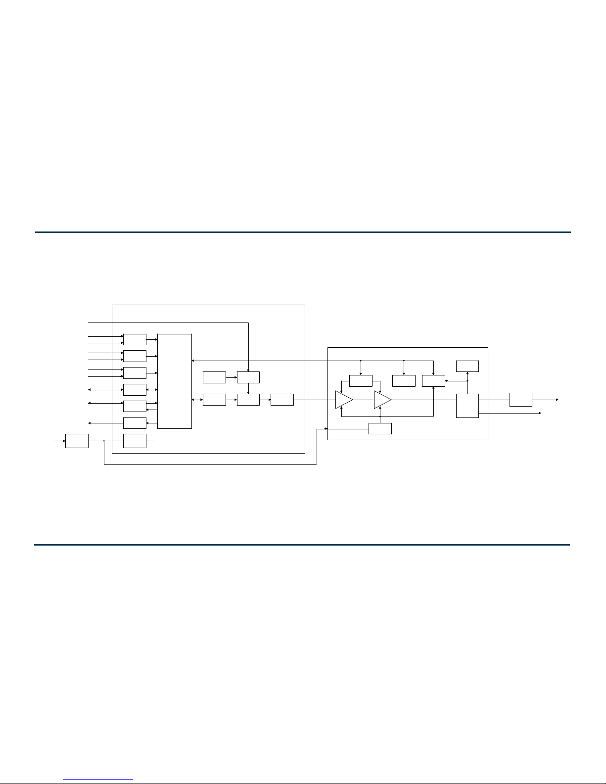
Refer to the functional block diagram: NV Series Transmitter Block Diagram - see page 1-9.
This section provides a high-level description of the transmitter’s key sections. The transmitter
circuitry is subdivided into four basic stages:
• Ac-dc power stage
• Control/monitor stage - see page 1-3
• RF drive stage - see page 1-4
• RF power stage - see page 1-6
NV30/NV40 electrical schematics
Some descriptions in this section refer to electrical schematics (SD-#s) . These are located in Section
5 of the NV30/NV40 Troubleshooting Manual.
Redundancy
The NV30/NV40 features redundancy in all key systems:
• RF power modules
• Exciters
• Cooling fans
• Cooling fan power supplies
• Low voltage power supplies
• SBC/AUI power supplies
Issue 3.3 2014-12-10 Page 1-1

NV30/NV40 Operations and Maintenance Manual Description
Ac-dc power stage
See electrical schematics SD-1 (A, B or C), SD-2 and SD-3.
The ac-dc power stage converts the ac power source to a positive dc voltage (PA volts) for the
transmitter's intermediate (IPA) and RF power amplifiers. The transmitter accepts a wide range of ac
input voltage options:
– 3-phase, 180 - 264 V ac (208 V ac nominal)
– 3-phase, 312 - 457 V ac (380 V ac nominal)
– 1-phase, 180 - 264 V ac (240 V ac nominal)
The ac-dc power stage provides power to operate cooling fans in the power supply modules, RF
power modules and reject load modules. It also provides power to the low voltage power supplies,
which generate the low level dc voltages (±15 V and +5 V) used throughout the transmitter, and to
the +12 V dc power supplies for the SBC (single-board computer) and AUI (advanced user interface).
The ac-dc power stage comprises ac input terminal blocks TB1, TB2 and TB3, an ac distribution
assembly (A6), a power supply distribution PWB (A7), SBC/AUI power supplies A (U1) and B (U2),
LVPS modules A (U3) and B (U4), fan power supply modules A (U7) and B (U8), IPA power supply
modules A (U9), B (U10) and C (U11), and dual PA power supply modules (U12 through U43) for
each of the 16 RF power modules. There is also a PS interface PWB associated with each power
supply module (fan, IPA and PA).
Power supply modules
See Figure SD-2. Power supply modules U9 through U43 convert the ac input voltage to a regulated
dc supply (IPA volts and PA volts) for 16 RF power modules (module contains both IPA and PA).
Each switching power supply module provides 2000 W output, at typical levels of 50 V and 40 A. The
modules regulate the output voltage based on a PA (or IPA) Volts Control input from the control/
monitor stage. Test points on the associated PS interface PWB allow monitoring of module presence
and ac input status. Each module has a built-in cooling fan and each senses out-of-regulation and
excessive temperature conditions and applies PS Fail and PS Temp alarm signals to the associated RF
power module. Both conditions cause the power supply to shut itself down, thus reducing the
transmitter's RF output.
The same modules are used for fan power supply modules U7 and U8. Their PS Fail and PS Temp
alarm signals, as well as the PS Module Present status signal, are applied to the control/monitor stage.
Page 1-2 Issue 3.3 2014-12-10

NV30/NV40 Operations and Maintenance Manual Description
LVPS modules
See Figure SD-1 (A, B or C). LVPS modules A (U3) and B (U4) convert the ac input voltage to the
regulated low voltage dc supplies. The +5 V, +15 V and -15 V regulated outputs of the supplies are
ORed together at the control/interface PWB (A1) and applied throughout the transmitter.
+12 V power supply modules
See Figure SD-1 (A, B or C). +12 V power supply modules A (U1) and B (U2) convert the ac input
voltage to the regulated +12 V dc supplies. The +12 V outputs are ORed together on the power
supply distribution PWB (A7) and a common +12 V supply is applied to the control/monitor stage.
Power supply distribution PWB
See Figures SD-1 (A, B or C) and SD-3. The power supply distribution PWB (A7) interfaces between
fan power supply modules U7 and U8 and the cooling fans for RF power modules 1 through 16 and
reject loads A, B and C. The fan voltage (+48 V) is applied via power rectifiers CR1 and CR2 to the
transmitter's cooling fans. A nominal 47 V is applied as Fan V Sample A and B to the control/monitor
stage for metering and fan PS fault detection.
The power supply distribution PWB also interfaces between SBC/AUI power supplies U1 and U2
and the control/monitor stage. +12 V is applied via power rectifiers CR3 and CR4 to the control/
monitor stage. A nominal +12 V is applied as +12V Sample A and B to the control/monitor stage for
metering and supply fault detection.
Control/monitor stage
See electrical schematics SD-4 and SD-5 and Figure 1.1 on page 1-4. The control/monitor stage
monitors critical samples and status/alarm signals from the ac-dc power stage, RF drive stage and RF
power stage. For example, RF power monitoring and RF power stage status information is applied to
the control/monitor stage. Based on the value and status of each input, the control/monitor stage
produces the appropriate control signals for the RF power stage to ensure the proper operation and
protection of the transmitter. The control/monitor stage also provides the remote control/monitor
interface for the transmitter.
The control/monitor stage comprises a control/interface PWB (A1), a remote interface PWB (A2),
an LCD touch monitor (U5) and a single-board computer (U6).
U5 is a 17-inch, colour LCD screen that is mounted on the front of the transmitter. It provides an
advanced user interface (AUI) for the transmitter. The AUI can be controlled by touch screen and is
also available as a flash graphic on any web-interfaced PC or handheld device via the internal NV web
server. See “Using the AUI” on page 2-2 for detailed information on AUI functionality.
Issue 3.3 2014-12-10 Page 1-3

NV30/NV40 Operations and Maintenance Manual Description
From RF Power Stage
From Ac-Dc Power Stage
AUI
To RF Power Stage
To Ac-Dc Power Stage
Control/
Interface
PWB
To RF Drive Stage
From RF Drive Stage
From Remote
Controller
To Remote
Monitor
(part of)
Remote
Interface
PWB
(part of)
Remote
Interface
PWB
The control/interface PWB contains push-button switches that provide backup control for the RF
on/off, local/remote, power increase/decrease and reset functions. It also contains LEDs that serve
as an alternate means to monitor status (local/remote and RF on/off), forward power level
(percentage indicators from 10% to 100% of maximum RF output power) and various alarms.
Figure 1.1: Control/Monitor Stage
RF drive stage
See Figure SD-6. The RF drive stage converts the exciter's RF output to the intermediate RF level
needed to drive the RF power modules. It consists of exciter A (A3), exciter B (A4, optional) and RF
drive splitter/changeover assembly (A5).
Exciter(s)
Refer to the functional block diagram: NVE300 Exciter Block Diagram - see page 1-10.
Exciters A (A3) and B (A4) are the RF drive sources for the transmitter. They accept the external
audio program and/or IBOC information (see the NV30/NV40 Installation Manual for details on
various program input types). The exciters’ main/standby operation is controlled locally using the
AUI, or remotely. The exciter outputs are applied to the RF drive splitter/changeover assembly (A5).
The exciter provides an RF drive signal of 130 W (in analog mode).
Page 1-4 Issue 3.3 2014-12-10

NV30/NV40 Operations and Maintenance Manual Description
RF drive splitter/changeover assembly
The RF drive splitter/changeover assembly (A5) controls the routing of the main and standby
exciters and provides the RF drive signals for the 16 RF power modules. The assembly is comprised
of the splitter/changeover PWB (A5A1), two 4-way RF drive splitter PWBs (A2 and A3), two
attenuator PWBs (A4 and A5) and eight 3 dB hybrid couplers (U1 through U8).
Exciter relay control
The RF drive outputs from exciters A and B are applied to the splitter/changeover PWB (A5A1) at
A5A1J1 and A5A1J2 respectively. The Exciter Relay Control input (A5A1J3-4) is a signal applied from
the control/monitor stage that controls relay A5A1K1.
• When exciter A is selected as the main RF drive source, the Exciter Relay Control input is open
circuit and relay A5A1K1 will be de-energized. Exciter A's output will be applied to 3 dB
hybrid coupler A5A1U1.
• When exciter B is selected as the main RF drive source, the Exciter Relay Control input is near
ground potential (0 V) and relay A5A1K1 will be energized. Exciter B's output will be
applied to 3 dB hybrid coupler A5A1U1.
Exciter drive splitter
The splitter/changeover PWB’s 3 dB hybrid coupler (A5A1U1) is connected as a splitter. The RF
drive source (A or B) selected by relay A5A1K1 is applied to A5A1U1’s input. The signal is split into
two equal amplitude signals that are 90° out-of-phase. These split signals are applied to 4-way RF
drive splitter PWBs A5A2 and A5A3.
4-way RF drive splitter
Each 4-way RF drive splitter PWB (A5A2 and A5A3) accepts an output from the exciter 3 dB hybrid
coupler and splits it into four equal amplitude signals, using three 3 dB couplers identical to A5A1U1.
The outputs of each 4-way RF drive splitter are applied to the final RF drive splitters.
Final RF drive splitters
3 dB hybrid couplers A5U1 through A5U8 (identical to A5A1U1) are connected as splitters. Each
coupler accepts an output of the 4-way RF drive splitters and splits the signal into two equal
amplitude signals that are 90° out-of-phase. These split signals are applied to attenuator PWB A5A4
and A5A5.
Attenuators
The attenuator PWBs (A5A4 and A5A5) accepts the outputs from the 4-way RF drive splitter PWBs
and attenuate each of the signals for application to the 16 RF power modules. Attenuation values are
set in order to balance the RF drive output levels.
Issue 3.3 2014-12-10 Page 1-5

NV30/NV40 Operations and Maintenance Manual Description
RF power stage
See Figures SD-7, SD-8 and SD-9. The RF power stage accepts the intermediate RF drive inputs from
the RF drive stage and generates the final RF output. It consists of 16 RF power modules, four
module backplane PWBs (A17, A32, A50 and A65), four 10 kW combiner/filters (A16, A31, A49
and A64), two 20 kW combiners (A30 and A63), a 40 kW combiner (A48), an output power probe
(A13), three reject load assemblies [A (A14, 8-input), B (A45, 4-input) and C (A46, 4-input)] and two
reject load interface PWBs [A (A15) and B (A47)].
RF power module
See Figure SD-7 (see the NV30/NV40 Troubleshooting Manual for a detailed RF power module
description) and
Each of the 16 RF power modules provides up to 2750 W (for NV40) or 2062.5 W (for NV30) of RF
output power and is comprised of an IPA power amplifier PWB, eight power amplifier PWBs, power
module interface PWB, combiner PWB, splitter PWB and six cooling fans. The intermediate RF drive
outputs from the RF drive stage are applied to the RF power modules via module backplane PWBs 14 (A17), 5-8 (A32), 9-12 (A50) and 13-16 (A65). Within each RF power module, the intermediate RF
drive signal is sampled and then drives the IPA amplifier. The IPA output is sampled then split to
drive the module's eight PAs. The IPA Volts and PA Vol t s inputs from the associated switching power
supply modules control the RF output of the IPA and eight PAs, respectively. The RF power module
receives alarm and status signals (PS Temp, PS Fail, PS AC Fail, and PS Module Present) from the ac-dc
power stage. The RF power module also provides a Pwr Supply Inhibit signal (one for each of the
power module’s dual supplies) to the ac-dc power stage, which, when active, inhibits the associated
switching power supply. A PA V Sample and IPA V sample from each RF power module is applied to
the control/monitor stage. The control/monitor stage supplies a PA Volts Inhibit signal, which
controls the PA outputs of the RF power module.
“RF Power Module Block Diagram” on page 1-11.
Module backplane PWB
See Figure SD-7. Each set of four RF power modules (1-4, 5-8, 9-12 and 13-16) has an associated
module backplane PWB which interfaces with all module inputs and outputs, except for the RF
output. It also provides the fan volts connections for the module's cooling fans. The setting of
dipswitches S1 through S4 assign a four-bit address for each specific module based on module
position. Jumper E1 is set to TERM on RF power module 16 (the last module) to terminate the RS485 serial communication cable.
Combiner/filters
See Figure SD-8. There are various stages of combiners used in the transmitter. All combining
follows a corporate (or binary) structure in that pairs of RF power blocks are combined throughout
the RF chain from the RF power modules to the RF output.
Page 1-6 Issue 3.3 2014-12-10

NV30/NV40 Operations and Maintenance Manual Description
10 kW combiner/filters
Each 10 kW combiner/filter (A16, A31, A49 and A64) is a 2-stage combiner that accepts the RF
outputs from four RF power modules and provides a single RF output. Each 10 kW combiner/filter
uses three 3 dB hybrid couplers - two of which are used in the initial pair of 5 kW combiners, which
each accept the outputs of two RF power modules. The equal amplitude, 90° out-of-phase
(quadrature) RF signals are combined at the 3 dB hybrid coupler outputs and applied to a third and
final, 10 kW 3 dB hybrid coupler. Again, the equal amplitude, quadrature RF signals are combined.
The combined output is applied to a 10 kW low pass filter before being applied to a 20 kW combiner.
Any amplitude or phase imbalances between 3 dB hybrid coupler inputs cause a proportional signal
to be applied to the applicable reject load assemblies. The amplitude of the 5 kW Rej Ld Pwr signals
(via J5 and J6) represents imbalance between the combined outputs of the first stage of combining.
The amplitude of the 10 kW Rej Ld Pwr signal (via J7) represents imbalance between the combined
outputs of the second stage of combining (differences in pairs of RF power modules).
20 kW combiners
The 20 kW combiners (A30 and A63), which are hybrid couplers, accept the RF outputs from the
10 kW combiner/filters. The equal amplitude, 90° out-of-phase (quadrature) RF signals are combined
at hybrid coupler outputs and applied to the 40 kW combiner.
Any amplitude and phase imbalances between the inputs of the 20 kW combiners causes a
proportional signal to be applied (via J1) to the applicable reject load assemblies. The amplitude of
the 20 kW Rej Ld Pwr signals represents imbalance between the combiner inputs.
40 kW combiner
The 40 kW combiner (A48), which is a hybrid coupler, accepts the RF outputs from the 20 kW
combiners. The equal amplitude, 90° out-of-phase (quadrature) RF signals are combined at the hybrid
coupler output and applied to the output power probe.
Any amplitude and phase imbalances between the inputs of the 40 kW combiner causes a
proportional signal to be applied (via J1) to the applicable reject load assembly. The amplitude of the
40 kW Rej Ld Pwr signal represents imbalance between the combiner inputs.
Output power probe
See Figure SD-8. The output power probe (A13) monitors the transmitter's forward and reflected
power and generates the Fwd Pwr Sample (A1J1) and Refld Pwr Sample (A2J1) signals applied to the
control/monitor stage for protection and monitoring. RF monitor PWB A3 provides a nominal 4.5 V
(NV40) or 3.7 (NV30) rms [at 40 kW (NV40) or 30 kW (NV30) signal at A3J1 for use with a
Issue 3.3 2014-12-10 Page 1-7

NV30/NV40 Operations and Maintenance Manual Description
modulation monitor or spectrum analyzer. RF sample PWBs A4 and A5 provide similar samples at
A4J1 and A5J1. These samples are applied to exciters A and B (if used) for use by the exciters'
adaptive pre-correction circuitry [for all-digital (HD) or hybrid (FM+HD) modes of operation] and
also by the AUI’s spectrum analyzer display.
Reject load assemblies
See Figure SD-9. Reject load assemblies provide a means to dissipate reject power from the outputs
of the combiner/filter's 3 dB hybrid couplers. Reject load assemblies contain power resistors to
dissipate reject power and cooling fans to regulate temperature. There are three different reject load
assemblies (A, B and C) used in the transmitter.
8-input reject load assembly ‘A’
Reject power generated by the 5 kW combining stage of any of the four 10 kW combiner/filter
assemblies is dissipated by resistors in 8-input reject load assembly ‘A’ (A14). Micro-strip transmission
lines (on 8-input reject load PWB A14A1) in close proximity to the reject load signals induce eight
true RF sample voltages of the associated reject power. These samples are peak detected and applied
to the control/monitor stage via reject load interface PWB ‘A’ (A15). The reject load interface PWB
provides an interface between the ac-dc power stage’s Fan Volts supply and the reject load assembly’s
cooling fans. It also acts as the interface between the cooling fans’ Rej Fan Tach signals and the
control/monitor stage.
4-input reject load assembly ‘B’
Reject power generated by the output combining stage of any of the four 10 kW combiner/filter
assemblies is dissipated by resistors in 4-input reject load assembly ‘B’ (A45). Micro-strip
transmission lines (on 4-input reject load PWB A45A1) in close proximity to the reject load signals
induce four true RF sample voltages of the associated reject power. These samples are peak detected
and applied to the control/monitor stage via reject load interface PWB ‘B’ (A47). The reject load
interface PWB provides an interface between the ac-dc power stage’s Fa n Volts supply and the reject
load assembly’s cooling fans. It also acts as the interface between the cooling fans’ Rej Fan Tach signals
and the control/monitor stage.
4-input reject load assembly ‘C’
Reject power generated by the output combining stage of either of the two 20 kW combiners or the
40 kW combiner is dissipated by resistors in 4-input reject load assembly ‘C’ (A46). Micro-strip
transmission lines (on 4-input reject load PWB A46A1) in close proximity to the reject load signals
induce three true RF sample voltages of the associated reject power. These samples are peak detected
and applied to the control/monitor stage via reject load interface PWB ‘B’ (A47). The reject load
interface PWB provides an interface between the ac-dc power stage’s Fa n Volts supply and the reject
load assembly’s cooling fans. It also acts as the interface between the cooling fans’ Rej Fan Tach signals
and the control/monitor stage.
Page 1-8 Issue 3.3 2014-12-10

NV30/NV40 Operations and Maintenance Manual
Issue 3.3 2014-12-10 Page 1-9
Figure 1.2: NV Series Transmitter Block Diagram
FAN
PWR
IPA
C1
A1
PA4
PA3
PA2
PA1
C2
A2
PWR
REJ
PWR
REJ
PWR
PWR
IPA
FWD
D1
B1
PA8
PA5
PA6
PA7
D2
B2
FWD
AUI
PWR
REMOTE CONTROL/
AC POWER
240VAC
AC POWER
208VAC
OR
3 PHASE
AC POWER
B
A
B
IPA
PWR
EXCTR
SUPPLY
SUPPLY
SBC/AUI
SUPPLY
PWR SUPPLY
MODULE C
MODULE A
PWR
REJ
PWR
PWR
FILTER
REJ
PWR
PWR
PROBE
POWER
MONITORING
1 PHASE
OR
3 PHASE
400VAC
A
SUPPLY
LV PWR
IPA
C
LV PWR
IPA
A
FWD
LV PWR
IPA PWR SUPPLY
PWR SUPPLY
PWR SUPPLY
PWR SUPPLY
SPLITTER
MODULE D
MODULE B
COMBINER
REFLD
SBC
REJ
REJ
OUTPUT
B2060004 VE
FAN PWR SUPPLY
EXCITER B
IPA PWR SUPPLY
EXCITER A
INTEGRAL EXCITER
FAN PWR SUPPLY
(OPTIONAL)
SUPPLY B
(OPTIONAL)
SBC/AUI PWR
SUPPLY B
(OPTIONAL)
PWR SUPPLY
PWR SUPPLY
SBC/AUI PWR SUPPLY
10KW POWER BLOCK
10KW POWER BLOCK
10KW POWER BLOCK
PWR SUPPLY
10KW POWER BLOCK
RF OUTPUT
(OPTIONAL)
IPA PWR SUPPLY
FAN PWR SUPPLY
16 WAY
SPLITTER
IPA PWR SUPPLY
FAN PWR SUPPLY
FAN SUPPLY
FAN SUPPLY
IPA PWR SUPPLY
SBC/AUI PWR
PWR SUPPLY
SUPPLY A
LV PWR SUPPLY
SYSTEM CONTROL
PWR SUPPLY
PWR SUPPLY
PWR SUPPLY
LOW PASS
NV30/NV40 Operations and Maintenance Manual
Issue 3.3 2014-12-10 Page 1-10
Figure 1.3: NVE300 Exciter Block Diagram
DAC
ADC
ADC
I/O
ADC
SUPPLY
PILOT/MPX SAMPLE
REMOTE INTERFACE
CONSOLE
COMPOSITE SCA
MPX
L/R
SCA GENERATOR
2 x AES/EBU
TOSLINK OPTICAL
EXTERNAL 10MHz REFERENCE
FPGA
TCXO OR
OCXO
EXCITER PWB
RF DAC
PLL & VCSO
FILTER &
PREAMP
BIAS
DAC
BIAS
POWER
VSWR
PROTECTION
FILTER
(OPTIONAL)
RF OUT
B2060001 VA
AC/DC
DSP
LINEAR
REGULATOR
PROBES
HARMONIC
SUPPLY
RS232
RF SAMPLE (-30dBc)
TEMP SENSE
POWER AMPLIFIER
85-264VAC
DC/DC
REGULATED
ASRC

NV30/NV40 Operations and Maintenance Manual
Issue 3.3 2014-12-10 Page 1-11
Figure 1.4: RF Power Module Block Diagram
FWD FWD
6
4
1
4-WAY
PWR PWR
7
8
5
2
3
4-WAY
SPLITTER
4-WAY
COMBINER
FWD
PWR
OUTPUT
B2060005 VB
IPA
4-WAY
SPLITTER
COMBINER
PWR SUPPLY 1
IPA PWR SUPPLY
PWR SUPPLY 2
RF DRIVE

NV30/NV40 Operations and Maintenance Manual Operating the transmitter
Section 2: Operating the transmitter
This section provides information about operating the NV30/NV40 transmitter:
• Using the AUI - see page 2-2
• Home page - see page 2-14
• Menu page - describing transmitter operations - see page 2-15
• Logs page - viewing transmitter log - see page 2-16
• Viewing tool menu panels - see page 2-25
• Viewing real-time meters - see page 2-40
• Presets - editing operational settings - see page 2-44
• Viewing transmitter status - see page 2-59
• Factory Settings - see page 2-61
• System Settings - see page 2-70
• User accounts - see page 2-79
• Changeover page - see page 2-83
• User settings - see page 2-84
• Remote I/O page - see page 2-104
Issue 3.3 2014-12-10 Page 2-1

NV30/NV40 Operations and Maintenance Manual Operating the transmitter
Using the AUI
The NV30/NV40 has an advanced user interface (AUI) that is displayed on a 17-inch, colour LCD
screen mounted on the front of the control cabinet (Figure 2.1). The AUI is controlled via touch
screen that you can also access using a PC and a web browser.
This section includes the following topics:
• Logging into the AUI on page 2-3
• Describing the AUI layout on page 2-9
• List of AUI pages on page 2-10
• Navigating from page to page on page 2-13
Figure 2.1: NV30/NV40 AUI
Page 2-2 Issue 3.3 2014-12-10

NV30/NV40 Operations and Maintenance Manual Operating the transmitter
Information is displayed in a series of pages (screens) that serve specific transmitter functions. The
AUI has the following configurable displays:
• Login Page (see Logging into the AUI on page 2-3)
• Events logs (see Logs page - viewing transmitter log on page 2-16)
• Instrumentation panels (Viewing instrument panels on page 2-27)
• Real-time meters (see Meters Page on page 2-40)
• Presets (see Presets - editing operational settings on page 2-44)
• Transmitter status (see Viewing transmitter status on page 2-59)
• Factory settings (see Factory Settings on page 2-61)
• System settings (see System Settings on page 2-70)
• User accounts (see User accounts on page 2-79)
• Changeover (see Changeover page on page 2-83)
• User settings (see User settings on page 2-84)
• Remote input/output configuration (see Remote I/O page on page 2-104)
See the complete AUI flow diagram illustrated in Figure 2.2 on page 2-5.
Logging into the AUI
The transmitter’s AUI provides a means to restrict local and remote access to transmitter control
functions to authorized users only. Users can create accounts that can be pre-defined to set access
restriction from view-only (no control), full control (all permissions), custom (select permissions) and
administrative control.
Remote access
To access the transmitter’s AUI remotely, perform the following steps:
1. Configure your network settings (see Setting up the network on page 2-85).
Issue 3.3 2014-12-10 Page 2-3

NV30/NV40 Operations and Maintenance Manual Operating the transmitter
2. On your router or firewall software, open ports 3501 (3501 is factory default, use corresponding
other port if changed) and 80 and close (restrict access to) all other ports. If you are using RDS
data, open port 7005. If you are using SNMP, open ports 161 (Agent) or 162 (Traps).
3. When properly configured as noted above, the login menu (see Figure 2.3 on page 2-9) will
appear in your web browser when IP address is accessed. Your IP address and any login
messages appear in a box at the top, beside the logo, and the current AUI software version
number appears along the bottom of the login window.
4. Log in to the AUI by entering the appropriate parameters in the login window.
• In the Language field, press the down-arrow to review a drop-down menu displaying the
available language options, and select one.
• In the User field, enter the username. Default is “Nautel”.
• In the Password field, enter the password. Default is blank.
Note:
The Nautel AUI is factory configured with a default login username and password. Nautel
recommends that you change the password to improve overall system security. See Changing the
password on page 2-81.
• Press Submit to accept your login parameters and display the AUI home page (Figure 2.6 on
page 2-14). Note: The opening screen (the Home page) will have the layout from the previ-
ous login session.
Note:
If you do not have a user account, it must be set up by an existing user with proper permissions.
See Adding an account on page 2-80.
Note:
If no login attempt is made after 60 seconds, a timeout feature will be activated and the web
browser will be need to be refreshed in order to attempt another login.
Page 2-4 Issue 3.3 2014-12-10

NV30/NV40 Operations and Maintenance Manual Operating the transmitter
Local access
When properly configured, (but without auto login selected) the login menu will appear on the transmitter 17-inch LCD touchscreen. Log into the AUI by entering the appropriate parameters in the login window.
• In the
Language
field, press the down-arrow to review a drop-down menu displaying the
available language options, and select one.
• In the User field, enter the username. Default is “Nautel”.
• In the Password field, enter the password. Default is blank.
• Press Submit to accept your login parameters and display the AUI home page (Figure 2.6 on
page 2-14). Note: The opening screen (the Home page) will have the layout from the previ-
ous login session.
• If auto login is set the AUI will appear automatically without the required previous steps (see
Setting auto login (local only) status on page 2-81).
Issue 3.3 2014-12-10 Page 2-5

NV30/NV40 Operations and Maintenance Manual Operating the transmitter
Page 2-6 Issue 3.3 2014-12-10

Issue 3.3 2014-12-10 Page 2-7 (Page 2-8 Blank)
Figure 2-2: NV Transmitter AUI Flow Diagram
Digital Outputs page 2-107
Menu
page 2-15
(Return to)
Home
page 2-13
HOME
page 2-14
Presets
page 2-44
Factory
Settings
page 2-61
System Configuration page 2-62
Transmitter Type page 2-63
Scaling page 2-64
System
Settings
page 2-70
Changeover
Page
page 2-83
User Accounts
page 2-79
Changing The Password page 2-81
Setting Autologin page 2-81
Changing Permissions page 2-81
User
Settings
page 2-84
Network Setup page 85
Notifications page 2-90
SNMP Configuration page 2-94
Upgrade Software page 2-72
Remote I/O
page 2-104
Digital Inputs page 2-105
Status
(same as Menu -
Transmitter Status)
page 2-59
Logs
page 2-16
Exciter TCXO page 2-73
Audio Input Calibration page 2-75
Turn On Delay page 2-76
Defaults page 2-76
External 10MHz page 2-97
FM Polarity page 2-78
Thresholds page 2-65
Redundant Supplies page 2-66
IPA Bias Balance page 2-67
PA Field Bias page 2-69
Reset page 2-71
IBOC Settings page 2-73
Digital Audio Inputs page 2-98
Time Setup page 2-100
NTP Servers page 2-101
Audio Low Thresholds page 2-102
Setting Call Sign/ID page 2-103
Email Configuration page 2-88
Exgine Settings page 2-91
Critical Parameters page 2-96
Spectrum Mask page 2-99
General page 2-47
Main Audio page 2-50
SCA page 2-52
RDS page 2-53
Other Settings page 2-56
Editing An Existing Account page 2-80
Adding An Account page 2-80
Set User Type/Permissions page 2-80
Removing An Account page 2-82
Analog Outputs page 2-109
Nautel Phone Home page 2-93

NV30/NV40 Operations and Maintenance Manual Operating the transmitter
IP address and login messages
AUI software version
Figure 2.3: Remote AUI Login Menu
Describing the AUI layout
The AUI begins with the Home page and all further navigation will start from this screen
(see Figure 2.4 on page 2-11).
Any user can view the AUI pages on the front panel of the transmitter, regardless of the login status;
however, only users with the appropriate permission level can access functions that alter the
transmitter control settings.
Users can access the login menu by pressing the Change User button located in the bottom banner
of the AUI when logged in locally. It should be noted that this same button is shown as
viewing the AUI remotely (see Figure 2.4 on page 2-11).
Log Out if
Issue 3.3 2014-12-10 Page 2-9

NV30/NV40 Operations and Maintenance Manual Operating the transmitter
List of AUI pages
Table 2.1 defines the available AUI pages.
Table 2.1: AUI Pages
AUI Page Function See Page
Home View meters, tool menu panels, choose options and
navigate to other pages.
Menu Choose options and navigate to other pages. page 2-15
Transmitter Log View transmitter event history. page 2-16
Tool Menu Choose tool menu panel options. page 2-25
Meters List View Choose meters for display. page 2-40
Presets Edit user-defined presets. page 2-44
Transmitter Status View transmitter’s current active faults and
operational status.
Factory Settings View critical transmitter parameters. page 2-61
System Settings Users determine critical system configuration
parameters.
User Accounts Set user permission rights and define user account
information.
page 2-14
page 2-59
page 2-70
page 2-79
Changeover Set main exciter and auto exciter changeover
function.
User Settings
Remote I/O Define remote digital inputs/outputs and configure
Set network information, configure email and alarm
notification parameters, configure Exgine interface
information, configure SNMP information, capture
critical parameters, set time and date, enable/
configure NTP servers and set call sign/ID.
analog outputs.
Each AUI page provides information about a specific transmitter function. All navigation through
the AUI pages begins on the main screen shown in Figure 2.4 on page 2-11.
Page 2-10 Issue 3.3 2014-12-10
page 2-83
page 2-84
page 2-104

NV30/NV40 Operations and Maintenance Manual Operating the transmitter
RF On
Menu
Forward
Date &
Time
Modulation
Level
RF Off
Status
Local/
Top
Banner
Bottom
Banner
Events
Remote
Reset
Tool Menu
Panel
Displays (up
to 4 on
screen or
one full
screen)
Log
Power
Mode,
Frequency
Set Point,
Reflected
Selected
Meters
Active
Exciter
Power
Active/Select
Activity
Window
Log Out /
Change
User
Preset
AUI
Reload
Figure 2.4: Using the AUI
The top banner is permanent on all AUI pages and includes:
• Nautel Logo: From any AUI page, press the displayed logo to reload the AUI and prompt
for a login. Press this if your local AUI stops responding.
• Date & Time: Displays the date (including day of the week, month, day and year) and current
time (see Time setup on page 2-100).
Transmitter: Displays the name of the active preset, current forward power (and power set
•
point based on the active preset) and reflected power levels as well as the operating mode
(FM, FM+HD, HD, etc.) and carrier frequency. (see Presets - editing operational settings on
page 2-44). Press Menu/Presets (bottom panel) to open the Presets page and edit this
information. Also the call Sign/ID is displayed here (see Setting call sign/ID on page 2-103).
• Preset: Displays the active preset. Press this area to open the Activate Preset menu and
select the active preset.
• Exciter: Displays the active exciter and the peak (red) FM modulation value. Press in the
Active Exciter field to shortcut to the
Changeover page. The active exciter is displayed in the
top, right corner (see Figure 2.4).
Issue 3.3 2014-12-10 Page 2-11

NV30/NV40 Operations and Maintenance Manual Operating the transmitter
• Forward Power: Displays the analog power output when in FM or FM +HD modes and displays the HD power output when in HD (only) mode.
The bottom banner is also permanent on all AUI pages and includes the following buttons, some of
which open other menus and displays:
• RF On: Press to enable the transmitter’s RF power stage. When the button is highlighted
green, RF is enabled (on). When the button is highlighted amber, a fault condition exists that
is preventing the RF power stage from turning on.
• RF Off: Press to disable the transmitter’s RF power stage. When button is highlighted in red,
RF is disabled (off).
Activity Window: Displays various messages to reflect specific user interface commands,
•
such as RF on/off, local/remote control, or reset.
•
Menu: Press to open the Menu page, which allows navigation to various other pages (see
Menu page - describing transmitter operations on page 2-15).
• Status: Press to open the Transmitter Status page (see Viewing transmitter status on
page 2-59), which provides current alarm and status details for the transmitter. When the
Status button is red, one or more alarms of “high” severity is currently being reported and
the transmitter is in an ‘off-air’ state. When the Status button is amber, “medium” or yellow
“low” one or more lower level alarms is currently being reported, but the transmitter is still
‘on-air’, possibly at reduced power. When the Status button is green, the transmitter is operating normally. In this case there are no alarms being reported.
• Logs: Press to shortcut to the Transmitter Log page, which displays historical alarm and sta-
tus records for the transmitter (see Logs page - viewing transmitter log on page 2-16).
Local/Remote: Displays the operational control status of the transmitter. From the touch
•
screen, press the desired button. If
Local is highlighted green, only local control of the AUI is
possible. If Remote is highlighted green, only remote control is possible (however local users
can still navigate through the menus and disable the RF output by pressing RF Off).
• Reset: Press to reset protection circuits and restore any RF power modules (and associated
power supplies) that were inhibited, but are now alarm-free.
• Change User/Log Out: Press to display a login menu. Enter your username and password,
then press Done. If you do not have a user account, see Factory Settings on page 2-61.
Change User button will display as Log Out while viewing AUI remotely.
Page 2-12 Issue 3.3 2014-12-10

NV30/NV40 Operations and Maintenance Manual Operating the transmitter
Press this button to exit
all menu pages.
The displays between the top and bottom menus, contains user selected pages. These pages provide
access to a variety of AUI functions such as transmitter status and hardware settings. The following
paragraphs describe how to use these pages.
Tool Menu: Display up to four panels on the screen at one time. To reveal the Tool M enu
•
options, press X in the upper right corner of one panel to close an existing panel, and then
press in the blank space to display a menu of panels (see Viewing tool menu panels on
page 2-25).
•
Meters: Displays the real-time meters that provide a system review of the transmitter
(see Viewing real-time meters on page 2-40).
Navigating from page to page
You can easily navigate through the AUI from its Home page (see Figure 2.6 on page 2-14) or Menu
page (see Figure 2.7 on page 2-15). During navigation, all Menu pages will feature a red exit page
button(see Figure 2.5). Press this button to exit the Menu page you are on and return to the Home
page.
Figure 2.5: Exit Page Button
Issue 3.3 2014-12-10 Page 2-13

NV30/NV40 Operations and Maintenance Manual Operating the transmitter
Home page
The Home page is the first screen to appear when you login into the AUI. You can return to the
Home page, from any screen, by pressing on the logo (upper left corner) or by pressing
.
Home
Figure 2.6: Home Page
Menu >
Press the Menu button to view the various sub-menu options (see Figure 2.7 on page 2-15).
Page 2-14 Issue 3.3 2014-12-10

NV30/NV40 Operations and Maintenance Manual Operating the transmitter
Menu page - describing transmitter operations
From the Home page, press the Menu button to view the Menu page (see Figure 2.7). The Menu
page displays icons that link to pages that control various transmitter operations.
Figure 2.7: Menu Page
Select Home to return to the home page (see Figure 2.6 on page 2-14).
Choose Presets to open screens related to presets (see Editing or creating presets on page 2-45).
Select Factory Settings to view various parameters relating to the transmitter (see Factory Settings
on page 2-61).
Press System Settings to access pages that allow users to reboot the AUI or active exciter, perform
software upgrades, configure IBOC Settings, set Audio Input Calibration, configure FM Polarity
etc. (see System Settings on page 2-70).
Issue 3.3 2014-12-10 Page 2-15

NV30/NV40 Operations and Maintenance Manual Operating the transmitter
Press User Accounts to access a page that displays a list of users with access to the AUI and,
depending on permission level, allows editing of user accounts (see User accounts on page 2-79).
Select Changeover to access a page that allows setting of the main (active) exciter and setup of
automatic exciter changeover (see Changeover page on page 2-83).
Press User Settings to access a page that allows network configuration, email configuration and
alarm notifications, setting of Exgine parameters, SNMP configuration, capturing critical parameters,
setting date and time, enabling and configuration of NTP servers and setting call sign (see User
settings on page 2-84).
Press Remote I/O to access a page that allows assignation of remote digital inputs and outputs as well
as the configuration of analog outputs (see Remote I/O page on page 2-104).
Logs page - viewing transmitter log
The Logs page allows you to review the transmitter’s event logs to check the operational status,
historical alarms, perform troubleshooting, or identify recent changes to transmitter controls. Press
Logs (located on bottom panel) on any AUI window to open this page (see Figure 2.8 on page 2-17).
This section includes the following topics:
• Viewing event logs on page 2-17
• Understanding the log manager window on page 2-19
• Filtering logs on page 2-20
• Copying logs on page 2-21
• Deleting logs on page 2-21
• Viewing the legend on page 2-24
Page 2-16 Issue 3.3 2014-12-10

NV30/NV40 Operations and Maintenance Manual Operating the transmitter
Page number of
displayed page
Navigate through
the table using
these arrows
first page
last page
page-by-page
row-by-row
page-by-page
row-by-row
Figure 2.8: Log page
Viewing event logs
The Logs page displays a “read only” chronological table of log events under the following column
headings (see Figure 2.8):
• Device - identifies the origin device of the alarm (e.g., Controller, Exciter, or RF Module).
Event - identifies the alarm name.
•
•
State - indicates whether the alarm state is active (red bell) or cleared (green checkmark) and
in some cases, indicates whether the RF was turned on or off. This column will also display
which control state (Local or Remote) the transmitter is in, which preset index was selected,
the frequency that is set and the power level.
• Severity - indicates how seriously the alarm affects transmitter operation.
Issue 3.3 2014-12-10 Page 2-17

NV30/NV40 Operations and Maintenance Manual Operating the transmitter
= low (RF output not affected)
= medium (RF output may be reduced)
= high (RF output may be inhibited)
Figure 2.9: Alarm Severity
• Time of Event - identifies the day-of-the-week, date and time of the alarm event.
To navigate through the table, press the arrow keys on the right-side of the screen or use the scroll
bar that appears when more than one page is available.
The table of log information can span over more than one page. The current page number is
identified above the table on the right-side of the screen. For example,
displayed page is one out of a possible four pages. Press the
Page button to reveal information about
Page 1/4 means that the
the pages.
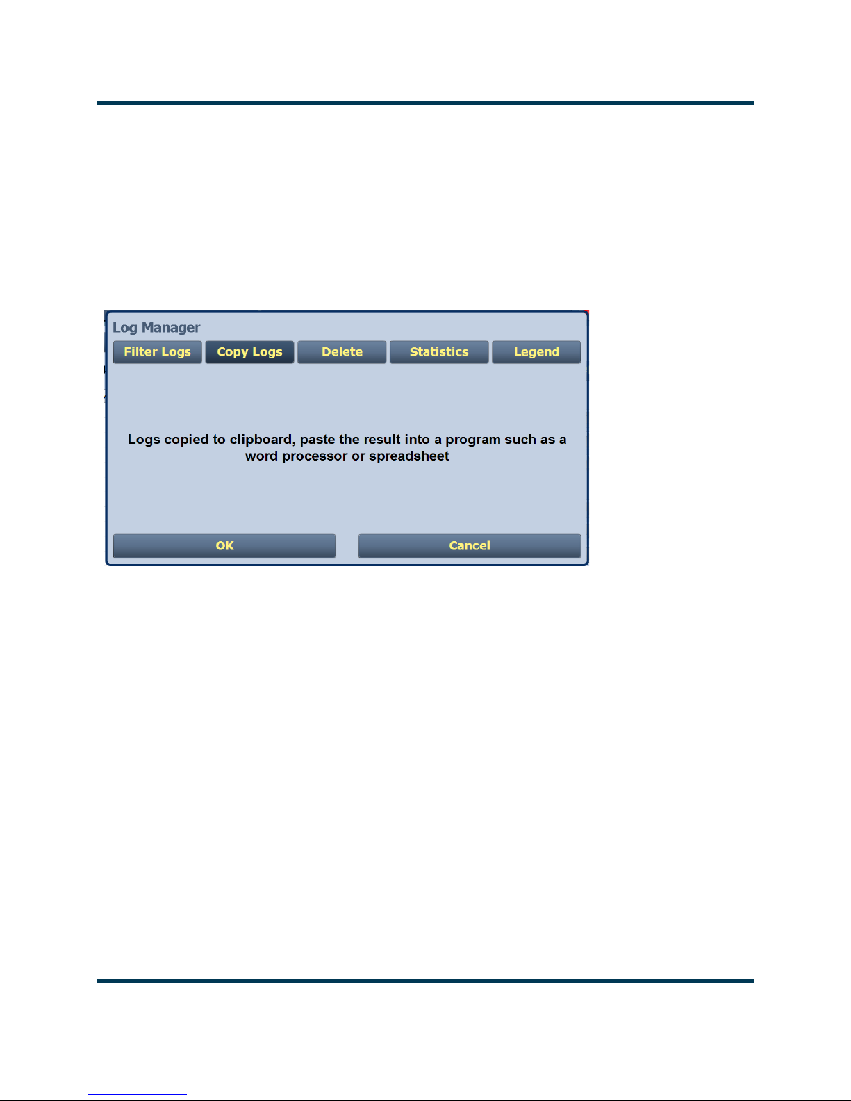
You can access a more detailed listing of events and resolve any alarm issues via the Log Manager
window. Pressing the Log Manager button on the Logs page will provide access to this window (see
Figure 2.9 on page 2-19).
Page 2-18 Issue 3.3 2014-12-10

NV30/NV40 Operations and Maintenance Manual Operating the transmitter
Tabs
Device type
Selection
Methods
Calendar
and Clock
Understanding the log manager window
The Log Manager window contains the functions that edit the logs listed in the Logs page. Press the
Log Manager button to open a configurable window with the following display options identified by
tabs across the top of the screen (see Figure 2.9):
• Filter Logs: Press to determine filter parameters by date and frequency.
• Copy Logs: Press to copy the selected logs (remote view only).
• Delete: Press to remove all selected logged events.
Statistics: Press to display detailed information about an event(s).
•
•
Legend: The Legend tab opens a “read only” display of alarm symbols to help you interpret
the ones listed in the Logs page or in the Statistics window (see Figure 2.14 on page 2-24).
Each of these tabs, opens a secondary window or changes the active window options to suit the tab
function.
Figure 2.9: Log Manager Window
Issue 3.3 2014-12-10 Page 2-19

NV30/NV40 Operations and Maintenance Manual Operating the transmitter
By Date Range
Controller
Exciter A
Exciter B
RF Module #
Filtering logs
You can filter transmitter events based on their device or date by clicking the Filter Logs button in the
Log Manager (see Figure 2.10).
Select a Device by pressing the Select a Device button to reveal the following event monitoring op-
tions in a drop-down menu:
– No Selection - displays all transmitter events (shown as Select a Device)
– Controller - displays controller events only
– Exciter A - displays exciter A events only
– Exciter B - displays exciter B events only
RF Module # - displays applicable RF Module # events only
–
Activate a log mode option by selecting the radio button besides it:
–
Get Next Batch - allows users to see log events in batches of 2000
– Filter by Date - activates the calendar portion of the screen and allows users to select a
date range
– Select All - selects all logs for display
Press OK to accept the configuration or press Cancel to close and return to Transm itter Log.
Figure 2.10: Log Manager - Filtering Logs
Page 2-20 Issue 3.3 2014-12-10
NV30/NV40 Operations and Maintenance Manual Operating the transmitter
Copying logs
You can create a copy of all the logs in the selected list while remotely logged into AUI (these are
copied to the remote user’s computer clipboard) by clicking on the Copy Logs button in the log
manager (see Figure 2.11). You can paste the tab-delimited text copy of the logs into a text editing
program such as Word, Excel, Notepad, etc. Press OK or Cancel to close and return to the
Transmitter Log.
Figure 2.11: Log Manager - Copying Logs
Deleting logs
You can delete all events or a selection of events by clicking on the Delete button in the log manager
(see Figure 2.12 on page 2-22).
Delete by date - activates the calendar and clock (24-hour clock) where users can press the arrows to
establish a date and time. Log events older than this date will be removed from the events list.
Delete All - removes all the logs in the list.
Press OK to accept the configuration or press Cancel button to close this window and return to the
Transmitter Log.
Issue 3.3 2014-12-10 Page 2-21

NV30/NV40 Operations and Maintenance Manual Operating the transmitter
Month Day Year Hours Minutes
Figure 2.12: Log Manager - Deleting Logs
Viewing log statistics
Users can view statistical information on the events being displayed by clicking on the Statistics
button in the Log Manager (see Figure 2.13 on page 2-23). The Statistics screen groups similar
events that occurred within the filtered period as well as the time and date of the earliest and latest
event occurrence for each event type. Use the scroll bar to move through the list or the up and down
arrow buttons to the right of the scroll bar (if applicable). If the event log display spans more than ten
rows, use the arrows on the side of the display to scroll to page up or down. The Statistics page will
look similar to the Logs page display but has additional headings (see Figure 2.13 on page 2-23):
–Device - refers to the device that is associated with the alarm i.e. Exciter, Controller, RF
Module, etc.
–Event - describes the alarm (e.g., Local/Remote switch)
–Severity - identifies the seriousness of the alarm.
–# Events - reveals the number of times the same alarm has occurred for the same device.
Page 2-22 Issue 3.3 2014-12-10

NV30/NV40 Operations and Maintenance Manual Operating the transmitter
–Earliest - refers to the first time of an alarm occurrence.
–Latest - refers to the last time of an alarm occurrence.
If an alarm has only one occurrence (i.e., # Events column is 1), then the time in the
“Earliest” column will be the same as the time in the “Latest” column. If an alarm has
more than one occurrence (e.g., # Events column is 4), then the “Earliest” column
reveals the time of the first alarm (back in time), while the “Latest” column reveals the
time of the last alarm (closest to the present).
Press OK or Cancel to close this window and return to the Transmitter Log.
Figure 2.13: Log Manager - Statistics
Issue 3.3 2014-12-10 Page 2-23

NV30/NV40 Operations and Maintenance Manual Operating the transmitter
Viewing the legend
The Legend tab is different from the other tabs. Press the Legend tab to display a window describing
the meaning of the symbols that appear in the
Figure 2.14).
Press OK or Cancel to close this window and return to the Transmitter Log.
Figure 2.14: Log Manager - Legend
State and Severity columns of the Logs page (see
Page 2-24 Issue 3.3 2014-12-10

NV30/NV40 Operations and Maintenance Manual Operating the transmitter
Viewing tool menu panels
The center area of the Home page screen displays up to 4 panels of instrument information. Users
can choose which panels to display from 9 possible information panels (see Figure 2.15).
This section include the following topics:
• Describing instrument panel options on page 2-26
• Viewing instrument panels on page 2-27
• Instrument panel procedures on page 2-27
• Available instrument panels on page 2-30
Figure 2.15: Tool Menu Panel Options
To view the instrument panel options , close an existing panel by pressing X (upper-right corner) and
then press the icon in the blank space to open the
Issue 3.3 2014-12-10 Page 2-25
Tool M e nu. Select an icon to display that panel.

NV30/NV40 Operations and Maintenance Manual Operating the transmitter
Describing instrument panel options
The following table describes instrument panel options:
Table 2.2: Tool Menu Panels
Tool Description Reference
Spectrum Displays a spectrum analyzer, capable of monitoring
the transmitter’s RF output spectrum and various RF
sections of the exciter. An audio spectrum analyzer is
also available to allow viewing of the composite
baseband.
EQ Frequency
Response
EQ Impulse
Response
EQ Filter Delay Displays the delay of the modulator’s EQ filter across
AM-AM Correction Displays the amplitude compensation being applied to
AM-PM Correction Displays the phase compensation being applied to the
Signal
Constellation
Displays the frequency response of the modulator’s
EQ filter.
Displays the impulse response of the modulator’s EQ
filter.
its bandwidth.
the magnitude signal.
phase signal.
Displays the phase and amplitude of the symbols
being modulated within an OFDM sub-carrier as dots
on a cartesian graph. Also displays timing, MER and
data carrier information.
See page 2-30
See page 2-32
See page 2-33
See page 2-34
See page 2-35
See page 2-36
See page 2-37
Lissajous Plot Displays a Lissajous figure that represents the
resultant vector (magnitude and phase) for the
applicable channels (either L and R or I and Q).
Power Distribution Displays a CCDF plot that indicates the probability of
exceeding a given power level, b ased on the a ver ag e
power level. Aids in determining pea k powe r
capability.
Page 2-26 Issue 3.3 2014-12-10
See page 2-38
See page 2-39

NV30/NV40 Operations and Maintenance Manual Operating the transmitter
Each panel has a tool bar at the top of the display
Backward one step
Forward one step
Maximize / Minimize
Cog (more settings)
Exit
Peak (jumps cursor to
the next peak)
Viewing instrument panels
Each instrument panel has a menu bar that may be different from other panels (see Figure 2.16).
Figure 2.16: Instrument Panel Menus
Instrument panel procedures
Procedure to view instrument readings on the panel:
• To display a cursor in the panel, touch the screen where you want the cursor (see Figure 2.17
on page 2-28). The cursor position is noted in the upper, right-hand corner of the panel (e.g.,
frequency and amplitude for the spectrum analyzer). Touch in other areas of the instrument
to provide a coarse adjustment of the cursor position.
• To make fine adjustments, use the backward and forward buttons (see Figure 2.16).
Issue 3.3 2014-12-10 Page 2-27

NV30/NV40 Operations and Maintenance Manual Operating the transmitter
Cursor
Tools to move cursor
and display information
• To enlarge/reduce the instrument panel, use the maximize/minimize buttons. Some instrument displays show more information when maximized.
– Most panels can be maximized to fill the whole screen, e.g., EQ Impulse Response (see
Figure 2.18 on page 2-29).
– Some panels display more information when maximized, e.g., Signal Constellation (see
Figure 2.19 on page 2-29).
• To display additional settings in the Spectrum Analyzer panel, touch the “cog” button (see
Figure 2.16 on page 2-27). Displays include resolution bandwidth, span, averaging rate and
the actual measurement source (transmitter output, audio analyzer, etc.) that is being displayed. Touch the “peak” button (see Figure 2.16 on page 2-27) to place the cursor on the
next successive peak in the spectrum.
Figure 2.17: Instrument Cursor Manipulation
Page 2-28 Issue 3.3 2014-12-10

NV30/NV40 Operations and Maintenance Manual Operating the transmitter
Maximize/Minimize buttons
Maximize/Minimize buttons
Figure 2.18: Instrument Panel - Expansion Example 1
Figure 2.19: Instrument Panel - Expansion Example 2
Issue 3.3 2014-12-10 Page 2-29
NV30/NV40 Operations and Maintenance Manual Operating the transmitter
Peak Cog
Available instrument panels
Spectrum Analyser
See Figure 2.20. The carrier level is normalized to its unmodulated carrier level at 0 dB. The graph
center is always at the carrier frequency, as defined by the active preset’s Frequency value
Masks are shown based on transmission mode and are defined by the latest versions of the following
standards:
•IBOC: NRSC-5
• European Standard: ETSI EN 302 018-2
• FCC CFR 47, Part 73.317 and IC BETS-6e
Note:
While very accurate, the spectrum analyzer may display artifacts (spurs) as some operating carrier
frequencies that are a function of the analyzer and are not actually present on the output of the
transmitter. If these spurious emissions are observed on the spectrum analyzer, Nautel
recommends that a calibrated, external spectrum analyzer be used to verify the presence of spurs.
.
Touch on the panel to display a cursor in the approximate area. The cursor position (frequency and
amplitude) is noted in the upper, right-hand corner of the panel. Touch other areas of this instrument
panel to provide a coarse adjustment of the cursor position.
Figure 2.20: Spectrum Analyzer
Page 2-30 Issue 3.3 2014-12-10
NV30/NV40 Operations and Maintenance Manual Operating the transmitter
Use the left and right buttons to make fine adjustments.
Use the maximize or minimize buttons as required.
Use the “peak” button to place the cursor on the next successive peak (moving left to right) in the
spectrum.
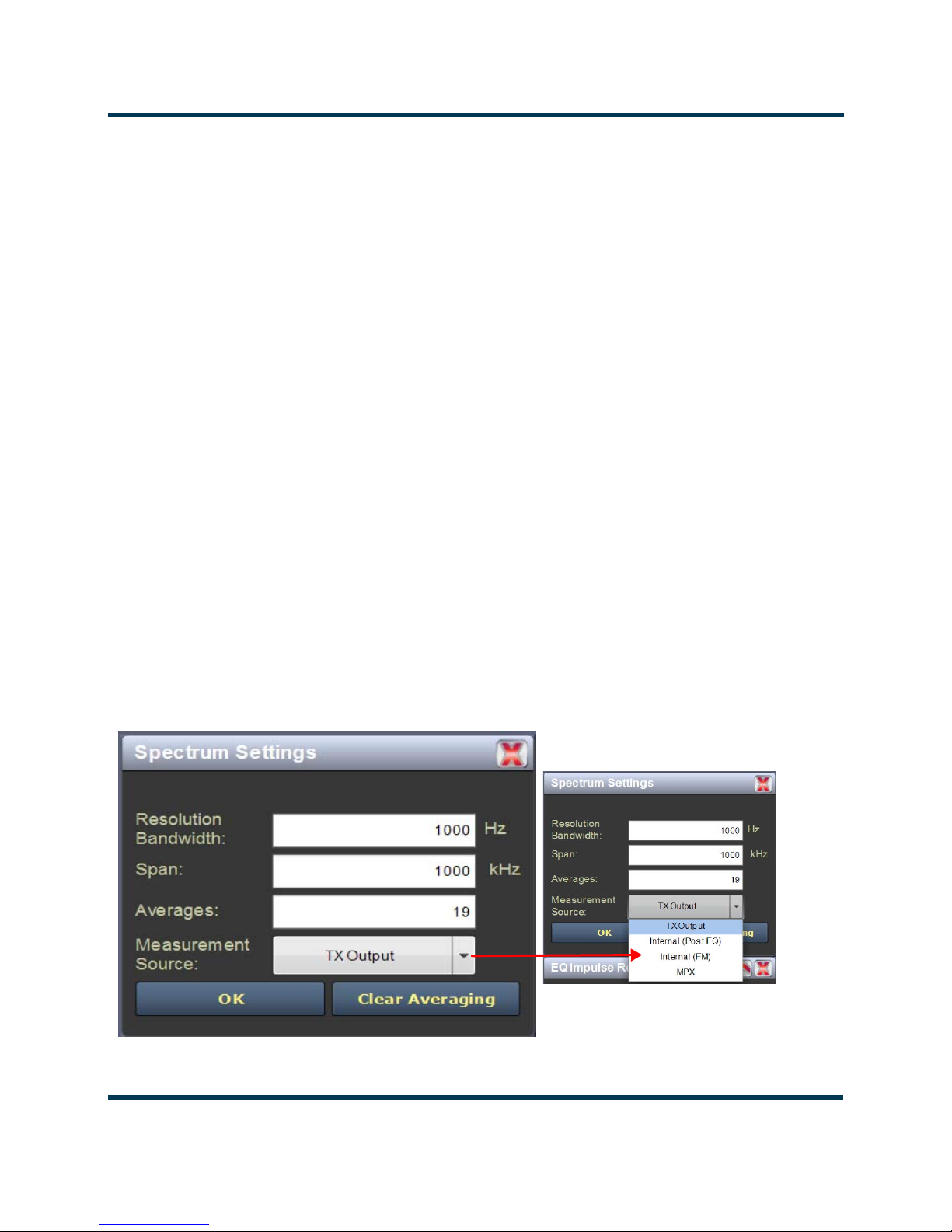
Use the “cog” button to gain access to spectrum settings (see Figure 2.21) such as:
• Resolution Bandwidth: determines the FFT bin size or the smallest frequency that can be
resolved. Allowable range is 75 - 10,000 Hz. Default setting is 1000 Hz.
• Span: determines the start and stop frequencies of the analyzer with the carrier frequency
always at the center. Allowable range is 10 - 1200 kHz. Default setting is 1000 kHz.
• Averages: determines the number of averages that the analyzer performs per sweep. Press
the Clear Averaging button to restart the averaging process. Allowable range is 0 - 100 kHz.
Default setting is 19.
• Measurement Source: determines the source of the spectrum plot (transmitter output,
audio analyzer, etc.) that is being displayed. Selecting TX Output uses the exciter’s RF sample
feedback signal to display the RF output spectrum. Selecting Internal (Post EQ) displays the
signal that will be produced by the exciter. Selecting Internal (FM) uses the exciter’s RF signal, before being equalized (if applicable). Selecting MPX shows the composite baseband
signal.
Figure 2.21: Spectrum Settings
Issue 3.3 2014-12-10 Page 2-31

NV30/NV40 Operations and Maintenance Manual Operating the transmitter
Equalizer screens
The NV30/NV40’s exciter includes a fixed equalizer to optimize audio performance. There are three
EQ instrument panels available in the Tool Menu - EQ Frequency (see Figure 2.22), EQ Impulse
Response
(see Figure 2.23 on page 2-33) and EQ Filter Delay (see Figure 2.24 on page 2-34).
Coefficients are selected based on channel frequency. All frequencies shown are relative to the
channel frequency.
Figure 2.22: EQ Frequency Response
EQ frequency response
See Figure 2.22. This panel displays the frequency response of the active exciter’s EQ filter. The panel
displays the gain of the filter with respect to the magnitude and frequency of the modulating signal. A
dashed line is displayed at the 0 dB level.
This tool is useful for installations featuring filter coefficients loaded to compensate for a channel
combiner response.
Touch on the panel to display a cursor in the approximate area. The cursor position (magnitude and
amplitude) is noted in the upper, right-hand corner of the panel. Touch in other areas of this
instrument panel to provide a coarse adjustment of the cursor position.
Use the left and right buttons as fine adjustments. Use the maximize or minimize buttons as required.
Page 2-32 Issue 3.3 2014-12-10

NV30/NV40 Operations and Maintenance Manual Operating the transmitter
Figure 2.23: EQ Impulse Response
EQ impulse response
See Figure 2.23. This panel displays the impulse response of the modulator’s EQ filter in the time
domain. This is a static display tool so the screen image is not fluid and will not change.
Touch on the panel to display a cursor in the approximate area. The cursor position (magnitude and
time) is noted in the upper, right-hand corner of the panel. Touch in other areas of this instrument
panel to provide a coarse adjustment of the cursor position.
Use the left and right buttons as fine adjustments.
Use the maximize or minimize buttons as required.
Issue 3.3 2014-12-10 Page 2-33
NV30/NV40 Operations and Maintenance Manual Operating the transmitter
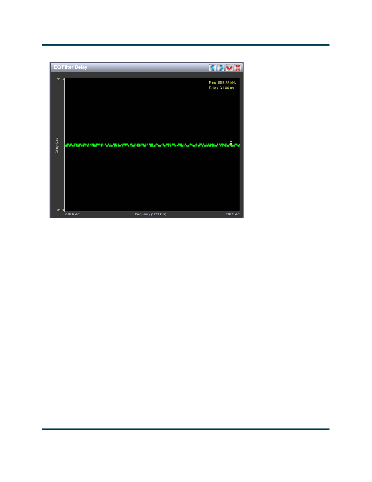
Figure 2.24: EQ Filter Delay
EQ filter delay
See Figure 2.24. This panel displays the delay of the modulator’s EQ filter across its bandwidth.
Touch on the panel to display a cursor in the approximate area. The cursor position (delay and
frequency) is noted in the upper, right-hand corner of the panel. Touch in other areas of this
instrument panel to provide a coarse adjustment of the cursor position.
Use the left and right buttons as fine adjustments.
Use the maximize or minimize buttons as required.
Page 2-34 Issue 3.3 2014-12-10

NV30/NV40 Operations and Maintenance Manual Operating the transmitter
AM-AM and AM-PM correction screens
When the transmitter is operating with digital carriers, the exciter linearizes the transmitter’s RF drive
signal by performing adaptive pre-correction. There are two correction parameters - AM-AM
Correction
(see Figure 2.25) and AM-PM Correction (see Figure 2.26 on page 2-36), which can be
viewed as an instrument panel.
Figure 2.25: AM-AM Correction
AM-AM correction
This panel displays the amplitude correction being applied to the RF drive signal in order to
compensate for the transmitter amplitude (gain) response, which is non-linear. The x-axis represents
the signal amplitude and the y-axis represents the gain correction applied for a given amplitude value.
A look up table (LUT) index value of 0 represents low transmitter output power (RF drive). A LUT
index value of 255 represents the maximum transmitter output power (RF drive).
The LUT curve can show that at low transmitter output power, more RF drive power is required to
connect for low final stage amplifier gain - the curve sharply increases as it drops to 0 table value.
(This low gain can also be overcome using additional bias, however pre-correction is more efficient.)
Equally, the curve could also increase sharply at the top end of the table, suggesting that high RF
drive power (gain) is required to connect for low gain at final stage amplifiers (PA compression peak
limiting). It is technically the inverse of the transmitter’s power amplifier gain response.
Touch on the panel to display a cursor in the approximate area. The cursor position (Gain and LUT
index) is noted in the upper, right-hand corner of the panel. Touch in other areas of this instrument
panel to provide a coarse adjustment of the cursor position. Use the left/right fine adjustment
buttons and the maximize/minimize buttons as required.
Issue 3.3 2014-12-10 Page 2-35
NV30/NV40 Operations and Maintenance Manual Operating the transmitter
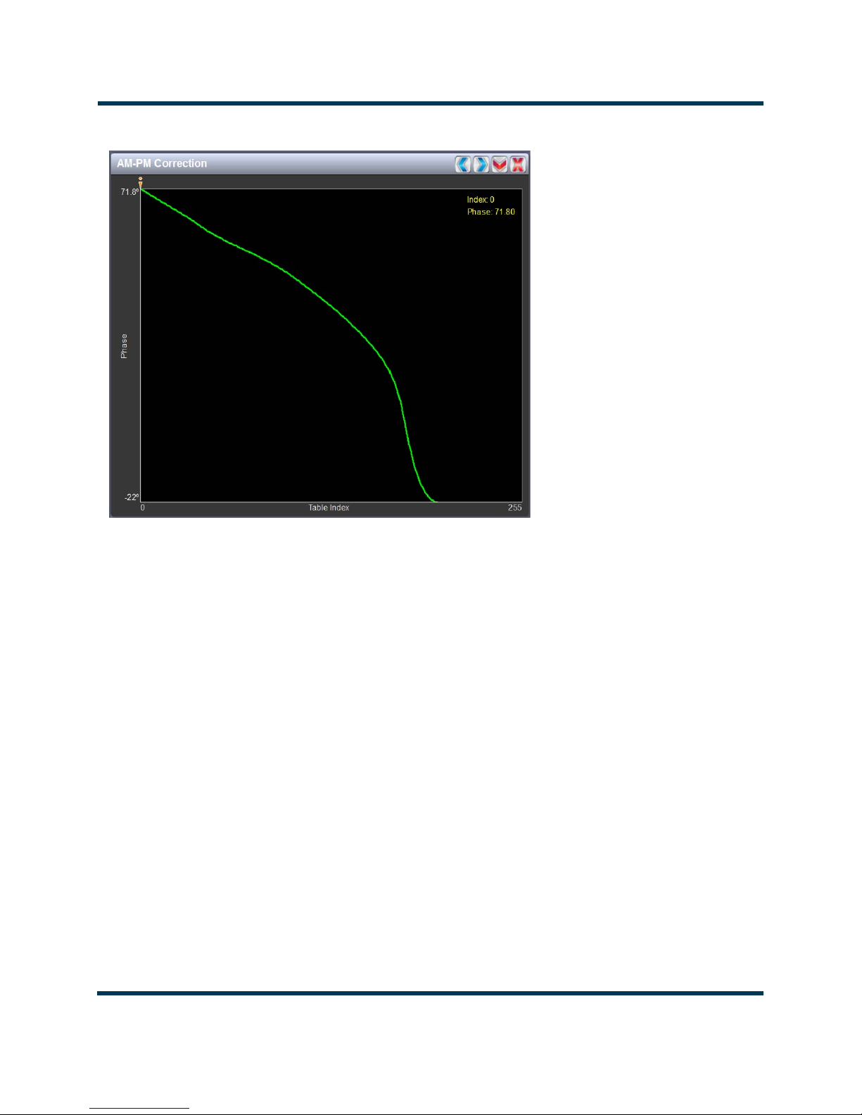
Figure 2.26: AM-PM Correction
AM-PM correction
This panel displays the phase correction being applied to the RF drive signal in order to compensate
for the transmitter’s (IPA +PA stage) phase non-linearity versus the output power. For example, in
Figure 2.26 the transmitter output power is low, so the curve in the plot shows positive phase
correction. Inversely, a negative phase correction will be displayed in the plot given high output
power levels. This correction is represented on the plot via the x-axis (table index value of between 0-
255). The y-axis represents the phase shift correction applied for a given amplitude value.
Touch on the panel to display a cursor in the approximate area. The cursor position (phase and LUT
index) is noted in the upper, right-hand corner of the panel. Touch in other areas of this instrument
panel to provide a coarse adjustment of the cursor position.
Use the left and right buttons as fine adjustments.
Use the maximize or minimize buttons as required.
Page 2-36 Issue 3.3 2014-12-10

NV30/NV40 Operations and Maintenance Manual Operating the transmitter
Figure 2.27: Signal Constellation
Signal constellation
See Figure 2.27. The exciter constantly measures the transmitter signal and performs basic
demodulation of the digital carriers. The Signal Constellation panel displays the phase and
amplitude of the symbols being modulated within an OFDM sub-carrier as dots on a cartesian graph.
There are separate screens for each sub-carrier. Typically, the dots will be grouped together around
the ideal data points. When the transmitter is on, the signal constellation display is representative of
the transmitter output. When the transmitter is off, the display is representative of the forward path
that will be transmitted.
Sub-carrier group information is shown in the lower, right section of the screen. Displayed
information includes the sub-carrier group name, the bandwidth that the selected carrier group
occupies and the modulation error ratio (MER) for the selected carrier group. MER quantifies the
performance of the transmitted digital signal as the ratio between the RMS power of the ideal signal
and the RMS power of the received signal’s error vector. A higher MER value is characteristic of a
smaller error, and therefore a higher quality signal. There is a NRSC minimum requirement of a MER
value of no less than 14 dB.
Use the scroll bar to select a higher or lower sub-carrier for viewing. Some sub-carriers are for timing
and synchronization. Others are modulated with data/content. Use the maximize or minimize
buttons as required.
Issue 3.3 2014-12-10 Page 2-37
NV30/NV40 Operations and Maintenance Manual Operating the transmitter
L and R mode
I and Q mode
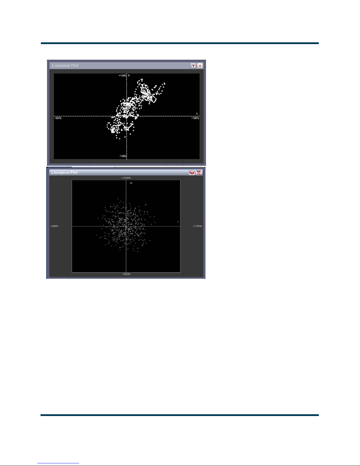
Figure 2.28: Lissajous Plot
Lissajous plot
See Figure 2.28. This panel displays a Lissajous figure that represents either L (left) and R (right)
audio content or a representation of the FM modulated signal [I (in-phase) and Q (quadrature)]. I and
Q will be automatically selected unless the transmitter is operating in stereo mode or not operating in
IBOC. Left and right audio content is displayed for all other audio sources.
The plot consists of a group of sequential samples to allow signal analysis. In L and R mode, the L+R
portion of the signal tends to dominate the plot, resulting in the majority of samples appearing in the
lower, left and upper, right quadrants. In I and Q mode, signals that are of equal frequency and 90
degrees out-of-phase result in a circular display.
Use the maximize or minimize buttons as required..
Page 2-38 Issue 3.3 2014-12-10

NV30/NV40 Operations and Maintenance Manual Operating the transmitter
Figure 2.29: Power Distribution Plot
Power distribution plot
See Figure 2.29. The exciter measures the relative power levels of the signal and determines the
probability of exceeding a given power level, relative to the average power. The data is plotted in the
Power Distribution Plot as a CCDF (complementary cumulative distribution function). The x-axis
displays the relative power level in dB, with the reference representing the average power. The average
power is 0db. The y-axis displays the probability of exceeding that power level. This plot can be used
to assess the distribution of a given signal, and provides an indication of the amount of peak power
capability required from the transmitter in order to prevent peak clipping/distortion of the output
signal.
Touch on the panel to display a cursor in the approximate area. The cursor position (power gain and
probability index) is noted in the upper, right-hand corner of the panel. Touch in other areas of this
instrument panel to provide a coarse adjustment of the cursor position.
Use the left and right buttons as fine adjustments.
Use the maximize or minimize buttons as required.
Issue 3.3 2014-12-10 Page 2-39

NV30/NV40 Operations and Maintenance Manual Operating the transmitter
HOME PAGE
Information
Selected
Meters
Buttons
View
Save
Arrow
Viewing real-time meters
The AUI can be used to display metered parameters on the Home page (see Figure 2.30), if selected
individually from the
This section includes the following topics:
• Describing the meter display on page 2-40
• Accessing meter information on page 2-41
• Identifying meter information on a specific sub-device on page 2-42
• Saving a meter list on page 2-43
Figure 2.30: Meters Page
Meters List View page or saved in a meter list layout and set to default.
Describing the meter display
The meters displayed in the AUI represent the active meters selected for display. Each meter is a
colour-coded bar with minimum and maximum values (see Figure 2.30). The current value for a
meter is indicated by an arrow on the colour-coded bar, as well as a numeric value below the meter.
• A parameter value in the green section of a meter bar indicates the parameter is within
the range for normal operation.
Page 2-40 Issue 3.3 2014-12-10

NV30/NV40 Operations and Maintenance Manual Operating the transmitter
Information
X
to close/delete
Buttons
(displays full
set of meters
for specific
sub-device)
Scroll Bar
• A parameter value in the yellow section (as applicable) of a meter bar indicates the
parameter is still within an operational range, but is approaching design limitations.
• A parameter value in the red section of a meter bar indicates the parameter is outside
normal operating conditions.
Accessing meter information
Procedures for accessing and editing information in the Meters section of the AUI screen:
• To delete a meter from the Home page, press X in the Meters window (Figure 2.31).
• To review all the meter options, press the meter list view shortcut
glass) at the top of the meters panel (see Figure 2.31). This will open the
window.
•On the Meter List View screen users can see all relevant meters of a sub-device. Select
the sub-device in question under the Transmitter Layout column and the Relevant
Meters
column will be populated. The desired Meters can now be selected.
Figure 2.31: Meters List View Window (Exciter A shown)
button (magnifying
Meter List View
Issue 3.3 2014-12-10 Page 2-41

NV30/NV40 Operations and Maintenance Manual Operating the transmitter
Identifying meter information on a specific sub-device
1. Open the Meters List View window and select one of the desired transmitter sub-devices.
– Controller
– Exciter A
– Exciter B
– RF Modules - Multiple modules supported
2. Under Transmitter Layout, press the information button (i) beside a device type. This will open
an information window in tabular format (see Figure 2.32).
Note:
When a meter value is updated, a blue box briefly appears around that value. Typically, updates
occur every one or two seconds.
3. To choose individual meters for display in the Meters window of the Home page: Select the
device type name in the Transmitter Layout panel and select the checkbox next to the desired
meters shown in the Relevant Meters panel (see Figure 2.31 on page 2-41). If the Relevant
Meters
the desired meter.
panel contains more than one page of information, use the scroll bar (right-side) to find
Figure 2.32: Meters - Information (Device type Controller shown)
Page 2-42 Issue 3.3 2014-12-10

NV30/NV40 Operations and Maintenance Manual Operating the transmitter
Saving a meter list
Note:
Meter lists are associated with user accounts. Lists saved in this screen are only displayed in the
current user account. Setting a list as default will define the meters that will appear when logging
into the current account (or after an ac power interruption in the local AUI if this is the default
user account).
To save meter specifics for display on the Home page:
Open the Meter List Save window from the Home page using the floppy disk button (Figure 2.33).
• Press Save As to save the currently displayed meters. Enter a name in the Layout Name
entry box and press OK.
• Press Delete to discard the selected meter list.
• Press Set Default to set the selected meter list as the default for the current user
account. The * symbol shows the default.
• Press Save to overwrite the selected meter list with the currently displayed meters.
• Press Load to display the meters saved under the currently selected meter list in the
Meters panel on the right-hand side of the Home page.
Figure 2.33: Meter List Save Window
Issue 3.3 2014-12-10 Page 2-43

NV30/NV40 Operations and Maintenance Manual Operating the transmitter
Active Preset
Access from the Menu page
Presets - editing operational settings
The Presets page (see Figure 2.34) allows users with the appropriate permissions to view operational
data (power level, frequency, mode, program input characteristics), plus create and control preset
settings. Users can create up to 62 presets or edit existing presets. To view the
Presets in the Menu page.
This section includes the following topics:
• Editing or creating presets on page 2-45
• Loading presets on page 2-46
• Understanding the preset tabs on page 2-47
Figure 2.34: Presets Page - General Tab
Presets page, select
Note:
When asked to enter a value in a field, an error message may appear (red text at the bottom of the
screen) showing the limits of the requested value. Re-enter the desired value, ensuring it falls within
the limits shown.
For example: Output Power - Valid values: 0.15kW to 5.5kW
Page 2-44 Issue 3.3 2014-12-10

NV30/NV40 Operations and Maintenance Manual Operating the transmitter
Editing or creating presets
When a presets page is opened from the menu, (for example see Figure 2.34 on page 2-44 or
Figure 2.37 on page 2-52), the
current operational state of the transmitter.
activated by pressing the Save button.
To edit a saved preset, you must load that preset from the Presets page (see Loading presets on
page 2-46). If the edited preset was active before it was edited, saving the preset will update the
preset, but the Current Settings will not change. To update the operation of the transmitter, reactivate the preset through the top banner (see Activating presets on page 2-46).
In the top banner (see Activating presets on page 2-46), an asterisk (*) appears next to the preset
name when the Current Settings have changed since the last preset was loaded. Current Settings are
not saved through an ac power cycle; when the transmitter recovers from an ac power loss, it loads
the preset that was last activated.
On the Presets page, an asterisk (*) appears next to the preset name in the header when there are
unsaved changes to the preset.
Current Settings of the transmitter are displayed. They define the
Current Settings can be edited and then immediately
When changes are complete, press the Save button and then press the Save Preset window’s Save
button to enable the changes. If you are creating a new preset, you can also enter a new name (e.g.,
Preset 4 - IBOC) in the preset window before clicking the Save or Save New button.
Parameters that can be edited are discussed in detail in Understanding the preset tabs on page 2-47.
To remove a preset, select it and press the Delete button.
To ignore any changes, press Cancel to return to the Presets page.
Note:
If you change an FM+HD or HD preset, particularly its power level or frequency, it is possible
to optimize the transmitter’s performance by adjusting the HD PA Volts value in the Mode
section of the Presets screen. For additional information see Improving transmitter performance for
IBOC presets on page 4-12 of this manual.
Issue 3.3 2014-12-10 Page 2-45

NV30/NV40 Operations and Maintenance Manual Operating the transmitter
CLICK HERE TO
DISPLAY PRESET
SELECTION
OPTIONS
Loading presets
When first entering the Presets page, the current “active” preset is displayed (see Figure 2.34 on page
2-44). If the current preset is not the desired one, use the
call up a window containing a list of available presets.
Load button on the left-side of the AUI to
Select the desired preset and press the
Delete button to delete the selected preset. Users cannot delete the current "active" (operational)
Load button to view or enable editing of the preset. Press the
preset or any preset that is referenced in the Remote I/O menu as either a remote input or output.
Those links in the Remote I/O menu must be deleted before the associated preset can be deleted.
Press Cancel to return to the Presets page.
Activating presets
In the Transmitter block in the AUI’s top banner, press the bar that contains the active preset name
and the drop-down arrow (see Figure 2.35). The Activate Preset window will appear, which contains
a list of all preset options. Press and highlight the desired preset and press the Activate button to
enable the preset as the transmitter’s active preset. Press the Cancel button to close this window.
Figure 2.35: Activating Presets
Page 2-46 Issue 3.3 2014-12-10

NV30/NV40 Operations and Maintenance Manual Operating the transmitter
Understanding the preset tabs
The Presets page consists of tabs across the top with functions on the left-side and parameters
displayed in the center and right-side of the window. A separate display appears for each of the
following tabs:
General - (see Figure 2.34 on page 2-44)
• Preset Name This field identifies the current preset settings. Users must load a preset to
directly edit this field (see Activating Presets on page 2-46).
• Output Power Set the output power level (in kW). Output power limits are a function of
the transmitter mode of operation (see Table 1-1 of the Pre-Installation
Manual for RF output power ratings for this transmitter).
• Frequency Set value. Valid frequencies are between 87.00 and 108.00 MHz.
• Mode Set the overall transmission mode. Available options are:
– FM: an analogue only mode, transmits a carrier, frequency modulated
with audio.
– HD: all digital mode; this mode transmits the upper and lower digital
sidebands of OFDM IBOC carriers. HD transmitter is typically high-level
combined (coupler or spatial) with a paired FM only transmitter. See page
2-48 for additional calibration settings. This mode requires additional
hardware.
– FM+HD: also known as hybrid/simulcast or low-level combined, this
mode transmits the analog carrier (FM modulated) and the upper and
lower digital sidebands of OFDM IBOC carriers. See page 2-48 for
additional calibration settings. This mode requires additional hardware.
– DRM+: transmits a DRM OFDM signal using the I/Q stream from a
DRM modulator connected to the desired AES input. See page 2-48 for
additional calibration settings. This mode requires additional hardware.
Note:
Settings on the Presets tabs are shown/hidden based on the chosen settings. Not all settings are
available in all modes.
Issue 3.3 2014-12-10 Page 2-47

NV30/NV40 Operations and Maintenance Manual Operating the transmitter
Mode - additional calibration settings:
– IBOC Injection (Lower): for FM+HD and HD modes, enter value, in dB,
between -20 and -10 dB for the IBOC injection level of the lower sideband of
digital carriers. This value determines the relationship between the digital
carriers power and the analog carrier power. Example: -20 dB indicates that
the total RMS power of the digital carriers will be 1/100 of the total RMS
power of the analog carrier. -10 dB indicates that the total RMS power of the
digital carriers will be 1/10 of the total RMS power of the analog carrier.
– IBOC Injection (Upper): for FM+HD and HD modes, enter value, in dB,
between -20 and -10 dB for the IBOC injection level of the lower sideband of
digital carriers. This value determines the relationship between the digital
carriers power and the analog carrier power. Example: -20 dB indicates that
the total RMS power of the digital carriers will be 1/100 of the total RMS
power of the analog carrier. -10 dB indicates that the total RMS power of the
digital carriers will be 1/10 of the total RMS power of the analog carrier.
Note:
The actual digital sideband power is 3dB less than that indicated in the upper or lower IBOC
Injection fields; i.e. if -20dBc is entered in the upper and lower IBOC Injection fields, the upper
and lower digital sideband power levels are actually -23dBc; this way, when added, the resultant
total digital power level is -20dBc.
For symmetrical sideband transmission: if -14dBc IBOC Injection level is desired (total digital
power of upper + lower sidebands is 4% of analog carrier power), set the upper and lower IBOC
Injection levels to -14dBc.
For asymmetrical sideband transmission, account for the fact that the actual sideband power level
is 3dB less than that shown. For example, if the upper digital sideband IBOC Injection level is
entered as -14dBc, the actual power level will be -17dBc. This is equally true for the lower digital
sideband.
–HD PA Volts: for FM+HD, HD and DRM+ modes, enter value, in volts,
between 25.0 V and 53.0 V. This value sets the drain voltage applied to the
PAs in the RF power modules, from their associated power supplies.
value affects
IBOC/DRM+ performance. Larger values result in an
improved spectrum, but decreased efficiency. Conversely, smaller values
result in improved efficiency, but degrade the spectrum. Typical values are
between 35 V and 50 V, and depend on many variables such as power
level, frequency and injection level.
This
Page 2-48 Issue 3.3 2014-12-10

NV30/NV40 Operations and Maintenance Manual Operating the transmitter
Note:
For additional information on operating FM+HD, HD and DRM+ presets, please refer to
Improving Transmitter Performance for IBOC Presets in Section 4 of this manual.
–HD IPA Volts: for FM+HD, HD and DRM+, enter value, in volts, between
25.0 V and 53.0 V. This value sets the drain voltage applied to the IPA in
the RF power modules, from their associated power supplies. This value
affects IBOC/DRM+ performance. Larger values result in an improved
spectrum, but decreased efficiency. Conversely, smaller values result in
improved efficiency, but degrade the spectrum. The default value is 50 V
and typically does not change.
– HD Power Boost: for FM+HD mode only. Enable this setting to engage
Nautel’s digital PowerBoost process, an advanced peak-to-average power
ratio reduction that increases hybrid-mode transmitter efficiency and
power capability. HD PowerBoost is only available in transmitters with
the appropriate exciter configuration.
Issue 3.3 2014-12-10 Page 2-49

NV30/NV40 Operations and Maintenance Manual Operating the transmitter
Figure 2.36: Presets - Main Audio
Main Audio - (see Figure 2.36)
:
• Audio Source Connects the appropriate exciter input for use. Available options are:
– Left/Right/Mono: this source allows for further configuration via
Analog Level, Audio Mode (Mono L+R, Mono L, Mono R, Stereo), 15kHz
Lowpass, Preemphasis, Main Audio Gain Adjust
settings. See page 2-51
for additional configuration information.
–MPX: this source allows for further configuration via the MPX Level
setting. See page 2-51 for additional configuration information.
–Primary Digital: this source allows for further configuration via Digital
Level, Audio Mode (Mono L+R, Mono L, Mono R, Stereo), 15kHz
Lowpass, Preemphasis, Main Audio Gain Adjust
settings. See page 2-51
for additional configuration information.
–Secondary Digital: this source allows for further configuration via
Digital Level, Audio Mode (Mono L+R, Mono L, Mono R, Stereo), 15kHz
Lowpass, Preemphasis, Main Audio Gain Adjust
settings. See page 2-51
for additional configuration information.
– MPX Over AES: this source allows for further configuration via the
Digital Level setting. See page 2-51 for additional configuration
information.
Page 2-50 Issue 3.3 2014-12-10

NV30/NV40 Operations and Maintenance Manual Operating the transmitter
Main audio - additional configuration settings:
– Analog Level: applies to Left/Right/Mono source only; enter value
between -12 and +12 dBu, which represents the input voltage level that
yields 100% modulation (typically 4.7 dBu).
– Digital Level: applies to Primary Digital, Secondary Digital and MPX
Over AES
sources only; enter value between -25.5 and 0 dBFS, with a
typical setting of -4 dBFS (100% modulation value).
–Audio Mode: select Mono L, Mono R, Mono L+R or Stereo (applies to
Left/Right/Mono, Primary Digital or Secondary Digital sources;
selecting
– 15kHz Lowpass Filter: applies to Left/Right/Mono, Primary Digital, and
Secondary Digital
Stereo applies a 19 kHz pilot).
audio modes; select On (applies 15 kHz low-pass filter
to audio input) or Off.
–Preemphasis:
select 0 us, 25 us, 50 us or 75 us. This setting applies to all
sources except MPX.
– Main Audio Gain Adjust: applies to Left/Right/Mono source only;
allowable range is -20 to 10 dB. This configuration setting will increase the
incoming signal level and yield a proportional increase in % modulation.
–MPX Level: applies to MPX source only. Set this parameter level in Vpp
(typically 3.5 Vpp - 100% modulation value). The allowable range for this
setting is between 1-5 Vpp.
Issue 3.3 2014-12-10 Page 2-51

NV30/NV40 Operations and Maintenance Manual Operating the transmitter
Figure 2.37: Presets - SCA
SCA - (see Figure 2.37)
:
• MPX SCA Connector (J7:A for SCA1, J7:B for SCA2) for use with an externally gen-
erated SCA; select Enabled or Disabled. When enabled, all the selections
listed below are active.
– Input Level: signal level that represents 10% modulation. Enter a value
between 1 and 5 V p-p (typically 2.83 Vpp).
• SCA Reduction Attenuation applied to the SCA input; set between 0 and 20% (used to
reduce the modulation level of the main audio when SCAs are enabled;
typically, for every 2% of SCA modulation, the main audio modulation
must be reduced by 1%).
• Internal SCA1/2 Enable or disable the appropriate internal SCA (SCA1 or SCA2). When
enabled, the settings listed below are active for the associated SCA signal
(1 or 2).
– SCA1 or SCA2 Injection Level: enter value between 0 and 20% (typically
10%); this level is added to the composite baseband signal.
– SCA1 or SCA2 Frequency: enter value between 20 and 100 kHz (typically
set to 67 kHz or 92 kHz).
–SCA1 or SCA 2 Input Level: enter value between -12 and +12 dBu, which
represents the input voltage level that yields 10% modulation (typically
4.7 dBu).
Page 2-52 Issue 3.3 2014-12-10

NV30/NV40 Operations and Maintenance Manual Operating the transmitter
– SCA1 or SCA2 Lowpass Filter: select Enabled (applies 7.5 kHz low-pass
filter to audio input) or Disabled.
– SCA1 or SCA2 Preemphasis:
– SCA1 or SCA2 Mode: select FM (frequency modulated sub-carrier, typical)
or DSB-SC (double side band suppressed carrier).
Figure 2.38: Presets - RDS
select 0 us, 50 us, 75 us or 150 us.
Note:
Refer to FCC guidelines for allowable modulation depth with SCAs or RDS enabled.
RDS - (see Figure 2.38)
:
• RDS When Enabled, all the selections listed below are active.
–RDS Local Echo: select Enabled or Disabled. When Enabled, the exciter
RDS port transceiver will echo all inputs and controls received back to the
terminal.
Issue 3.3 2014-12-10 Page 2-53

NV30/NV40 Operations and Maintenance Manual Operating the transmitter
–Data Source: select Ext. UECP, Internal RBDS, Internal RDS or Ext.
ASCII, ASCII Over IP, UECP Over IP.
–Injection Level: enter value between 0 and 10% (typically 5%). This level
is added to the composite baseband signal.
–Phase: enter value in degrees.
–Baud Rate: select 75, 150, 300, 600, 1200, 2400, 4800, 9600, 19200,
38400 or 57600 bps. This selection does not apply to internal data sources.
– PI Code (hex): (programme identification code) this unique code is used
to identify a broadcast station. Every station gets assigned a specific code
with a country identifying prefix. In the USA this code is determined by
applying a formula to the station's call sign. Additional information can be
found at www.nrscstandards.org. This selection applies to internal data
sources only.
–PS Code: (programme service code) this is simply an eight-character static
display that represents the call letters or station identity name. Most RDS
capable receivers display this information and, if the station is stored in
the receiver's presets, will cache this information with the frequency and
other details associated with that preset. This selection applies to internal
data sources only.
–PTY: this coding of up to 31 pre-defined programme types allows users to
find similar programming by genre. This selection applies to internal data
sources only.
–PTYN: (programme type name) this field can be used for detailed
description of the PTY by 8 digits. Example: if the PTY is 4 (Sport) a PTYN
like "Cycling" could be transmitted. The PTYN is intended for displaying
additional information only and cannot be used for automatic station
tuning like the PTY. The PTYN is optional and not obligatory. This
selection applies to internal data sources only.
– Music/Speech: select Music or Speech. This selection applies to internal
data sources only.
Page 2-54 Issue 3.3 2014-12-10

NV30/NV40 Operations and Maintenance Manual Operating the transmitter
–Traffic Info: select None, TA (Traffic Announcement) , TP (Traffic
Programme) or TA +T P. The receiver can often be set to pay special
attention to this flag and, for example, stop the tape/pause the CD or
retune to receive a traffic bulletin. The TP flag is used to allow the user to
find only those stations that regularly broadcast traffic bulletins whereas
the TA flag is used to signal an actual traffic bulletin in progress. This
selection applies to internal data sources only.
– Alternate Frequencies: select None or 1 through 6. This allows a
receiver to re-tune to a different frequency providing the same station
information when the first signal becomes too weak. This is often utilized
in car stereo systems. This selection applies to internal data sources only.
– Artificial Head: select Ye s or No. This selection is a decoder
identification operating mode flag.
– Compression Flag: select Yes or No. This selection is a decoder
identification operating mode flag.
–Dynamic: select Yes or No. This selection is a decoder identification
operating mode flag.
– Stereo: select Ye s or No. This selection is a decoder identification
operating mode flag.
Note:
Refer to FCC guidelines for allowable modulation depth with SCAs or RDS enabled.
Issue 3.3 2014-12-10 Page 2-55

NV30/NV40 Operations and Maintenance Manual Operating the transmitter
Figure 2.39: Presets - Other Settings
Other Settings - (see Figure 2.39)
:
• Other Settings Provides the following sub-functionality:
– Pilot Level: enter value between 6 and 12 % (typically 9 %). This level is
added to the composite baseband signal.
– Pilot 1 PPS Sync: select Enabled.
–Pilot Sync Phase:
if Pilot 1 PPS Sync is enabled, enter value between 0
and 360 degrees (typically 0 degrees).
–Sample Output: determines which sample signal will be present on
exciter’s rear panel PILOT/MPX SAMPLE OUT BNC connector. Select
Pilot
(default setting, pilot sample present) or MPX (Composite)
(composite baseband signal present).
– Audio Delay: select Enabled, then enter value in the allowable range of
0-12000 ms
. Default is 0. Audio Delay is used to time align the receiver
output of decoded analog and digital audio signals.
Page 2-56 Issue 3.3 2014-12-10

NV30/NV40 Operations and Maintenance Manual Operating the transmitter
– Auto Changeover Action: users can select which preset they want the
transmitter to switch to in the event of an automatic exciter changeover.
This function is ideal for changing to a preset that has a different HD PA
Volts value, which is required when a different exciter is active - e.g. HD
Power Boost active exciter A requires less HD PA Volts to comply with
spectral mask, thus improving dissipation. However if an automatic
changeover to non-HD Power Boost enabled exciter B occurs, the Auto
Changeover Action
preset will have a higher HD PA Volts value (less
efficient, but required in order to comply with spectral limits).
–Mod Loss Timeout: select Enable if so required. If Enable is selected the
following sub-fields will appear:
– Action: select the action to take on the loss of a modulating signal
post the timeout period. Select None (no resulting action), Inhibit
(inhibits the RF output and fans until the audio returns) or Change
Preset
(changes the active preset).
– Mod Loss Preset: displayed only if Action is set to Change Preset.
Select the preset from the drop down list that will activate upon the
loss of a modulating signal, post the timeout period.
– Timeout Minutes: sets the delay, in minutes, between modulation
loss detection and the resulting action. Enter a value in the allowable
range of 0 and 255 minutes.
– Timeout Seconds: sets the delay, in seconds, between modulation
loss detection and the resulting action. Enter a value in the allowable
range of 0 and 59.9 seconds.
Threshold: sets the threshold for modulation loss detection. Enter
–
a value in the allowable range of 0 and 100%.
–Hard Limiter: select Enabled, then enter the hard limit threshold
percentage (allowable range is 0-160%, defaulted to 140%). If enabled,
the modulation level will be limited (audio signal clipped or distorted) if it
exceeds the hard limit threshold.
Issue 3.3 2014-12-10 Page 2-57

NV30/NV40 Operations and Maintenance Manual Operating the transmitter
–AGC Limiter: select Enabled, then enter AGC Limit percentage (allowable
range is 0-160%, defaulted to 120%) and Time Constant (allowable range
is 0-1000 ms, defaulted to 0 ms). If Enabled, when the modulation level
exceeds the AGC Limit, the gain of the audio input will instantly decrease
in order to reduce the modulation level below the AGC limit threshold.
Recovery from this audio gain reduction is dependent on the Time
Constant
delay (fast attack, slow recovery). The input signal is briefly
distorted by the audio gain reduction when the threshold is exceeded.
–Two Slope Limiter: if Enabled, when the modulation level exceeds the
Threshold, the gain of the audio input will instantly change according to
the gain percentage setting (percentage of the initial gain, that which is
below the threshold). The input signal is distorted by the audio gain
change.
–Threshold (allowable range is 0-160%, defaulted to 120%).
–Gain (allowable range is 0-100%, defaulted to 56.2%).
–L/R Limiter: this look-ahead limiter can be applied to the signal
immediately before the stereo generator in the exciter. It has a fixed attack
time (and corresponding delay) of approximately 1 ms. It can be
configured to reduce the signal, if the gain setting is 0 dB or less, or can be
used to perform an AGC function and boost quiet sections of the audio if
a positive gain setting is used. If Enabled, enter the following parameters:
– Max Gain (allowable range is -20 to 20 dB, defaulted to 0 dB).
– Decay Time (allowable range is 0 to 60 s, defaulted to 0 s).
– Hold Time (allowable range is 0 to 60 s, defaulted to 0 s).
MPX Power Limiter: if Enabled, enter MPX RMS Limit . This limit
–
allows the broadcast signal to remain in compliance with the MPX power
limits as suggested in ITU-R BS.412-9. While the limiter will keep the
transmitter in compliance, it is recommended that adjustment to the
processing be made in such a way as to minimize the reductions
performed by the limiter. Otherwise, the signal will not take advantage of
the peak modulation capability available.
–
MPX RMS Limit (allowable range is -12 to 12 dBr, defaulted to 0 s).
Page 2-58 Issue 3.3 2014-12-10

NV30/NV40 Operations and Maintenance Manual Operating the transmitter
Viewing transmitter status
You can view the NV30/NV40’s operational status using the Transmitter Status page - see
Figure 2.40. This page shows current active alarms and status to aid in fault diagnosis. To view the
Transmitter Status page, select
This section includes the following topics:
• Viewing alarm details on page 2-60
• Status button colour indications on page 2-60
• Resetting alarms on page 2-60
Figure 2.40: Transmitter Status page
Status from the AUI bottom banner.
Issue 3.3 2014-12-10 Page 2-59

NV30/NV40 Operations and Maintenance Manual Operating the transmitter
= low (RF output not affected)
= medium (RF output may be reduced)
= high (RF output may be inhibited)
Viewing alarm details
The Transmitter Status page - see Figure 2.40 on page 2-59 displays a table that lists the active alarm
details under the following columns:
• Device - identifies the alarms by their originating device (e.g., Controller, Exciter A, etc.)
• Alarm - identifies the type of alarm (alarm name).
• Level - identifies the severity level of the alarm.
Note:
When viewing alarms, cross reference the alarm name, (which appears in the Alarm column of the
Transmitter Status page) with Table 1.1 of the Troubleshooting Manual.
Status button colour indications
• When the Status button is red, one or more active alarms are indicating that the transmitter
may be in an ‘off-air’ state.
• When the Status button is amber, one or more active alarms are indicating that the transmit-
ter is still ‘on-air’, but may be at reduced power.
• When the
ing normally.
Status button is green, no alarms are being reported and the transmitter is operat-
Resetting alarms
When an alarm is present, use the Reset button, at the bottom of any AUI screen, (see Figure 2.41) to
clear any latching alarms that are holding the transmitter in an “off-air” state. If the offending alarm
has cleared, then the transmitter should resume operation.
Figure 2.41: Reset Button
Page 2-60 Issue 3.3 2014-12-10

NV30/NV40 Operations and Maintenance Manual Operating the transmitter
Factory Settings
Values for critical parameters are set using the Factory Settings page (see Figure 2.42), which is
accessed from the
the page to open related information on the right-side of the page.
WARNING: Device settings are established at the factory and should not
require any adjustment. These settings affect critical system protection
circuits. Making changes to these settings may void your warranty.
Contact Nautel before making changes.
This section includes the following topics:
• System configuration on page 2-62
• Transmitter type on page 2-63
• Scaling on page 2-64
Menu page. To use this page, simply select an item from the list on the left-side of
• Thresholds on page 2-65
• Redundant supplies on page 2-66
• IPA bias balance on page 2-67
• PA field bias on page 2-69
Figure 2.42: Factory Settings
Issue 3.3 2014-12-10 Page 2-61

NV30/NV40 Operations and Maintenance Manual Operating the transmitter
System configuration
This factory setting (see Figure 2.43) configures the type of system the transmitter will be part of, sets
ALC Limit (in %), and sets the cooling Fan Voltage.
the
•System Type
– Standalone: indicates the transmitter operates by itself.
– SC1 Combined: indicates the transmitter operates as part of a combined
system and is controlled by the SC1 system controller.
– N+1: Indicates the transmitter operates as part of a main/standby or +1
backup for N other transmitters, and is under the control of the SC1
system controller.
•ALC Limit Allowable range is 0-135%, with a typical value of 100%. ALC limit allows
the transmitter to compensate for any power shortfall by setting DAC
limit at a higher percentage than should be required.
• Fan Voltage
Figure 2.43: Factory Settings - System Configuration
Allowable range is 30-53V, with a the typical value of 48V.
WARNING: Device settings are established at the factory and should not
require any adjustment. These settings affect critical system protection
circuits. Making changes to these settings may void your warranty.
Contact Nautel before making changes.
Page 2-62 Issue 3.3 2014-12-10

NV30/NV40 Operations and Maintenance Manual Operating the transmitter
Transmitter type
This factory setting parameter (see Figure 2.44) allows for setting the transmitter type (NV5, NV10,
NV20 etc.). This setting is one-time, factory configured and cannot be changed.
Figure 2.44: Factory Settings - Transmitter Type
WARNING: Device settings are established at the factory and should not
require any adjustment. These settings affect critical system protection
circuits. Making changes to these settings may void your warranty.
Contact Nautel before making changes.
Issue 3.3 2014-12-10 Page 2-63

NV30/NV40 Operations and Maintenance Manual Operating the transmitter
Scaling
This factory setting (see Figure 2.45) supports the calibration of various metered parameters.
Figure 2.45: Factory Settings - Scaling
WARNING: Device settings are established at the factory and should not
require any adjustment. These settings affect critical system protection
circuits. Making changes to these settings may void your warranty.
Contact Nautel before making changes.
Note:
FM and FM+HD modes display analog tranmitter power output in the top banner of the AUI.
HD and DRM+ modes display total digital RMS power. For FM+HD if the total RMS
power is desired, see applicable meters in controller device list. See Identifying meter information on
a specific sub-device on page 2-42.
Page 2-64 Issue 3.3 2014-12-10
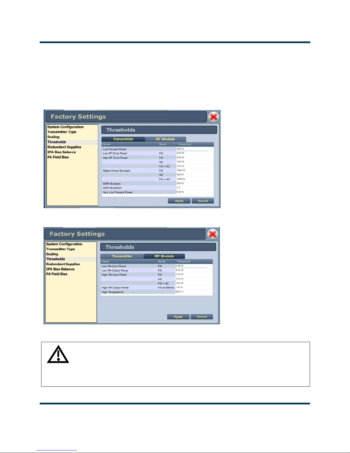
NV30/NV40 Operations and Maintenance Manual Operating the transmitter
Thresholds
This factory setting (see Figure 2.46 and Figure 2.47) supports the setting of alarm thresholds for
critical parameters. Select the desired threshold from the list located in either the
Module
tabs and touch the applicable field to enable editing. The current threshold is displayed.
Enter the new threshold and press Apply to save changes.
Figure 2.46: Factory Settings - Thresholds (Transmitter) - Default Values Shown
Transmitter or RF
Figure 2.47: Factory Settings - Thresholds (RF Modules)- Default Values Shown
WARNING: Device settings are established at the factory and should not
require any adjustment. These settings affect critical system protection
circuits. Making changes to these settings may void your warranty.
Contact Nautel before making changes.
Issue 3.3 2014-12-10 Page 2-65

NV30/NV40 Operations and Maintenance Manual Operating the transmitter
Redundant supplies
This factory setting (see Figure 2.48 ) supports configuring redundant fan, IPA, LVPS and 12 V
power supplies. Select
standalone.
Figure 2.48: Factory Settings - Redundant Supplies
Ye s (default) if the supply operates as a redundant set. Select No if the supply is
WARNING: Device settings are established at the factory and should not
require any adjustment. These settings affect critical system protection
circuits. Making changes to these settings may void your warranty.
Contact Nautel before making changes.
Page 2-66 Issue 3.3 2014-12-10

NV30/NV40 Operations and Maintenance Manual Operating the transmitter
IPA bias balance
IPA Bias Balance (see Figure 2.49 on page 2-68) allows for optimal balancing of RF power module
outputs to minimize reject load power. An
when balancing is suggested. This may occur after an RF power module has been replaced or
repaired. While RF is enabled (on) and the transmitter is operating at the desired power level in the
desired preset, press the
the Save and Cancel buttons will activate to either save the result to the active preset or abort the
function without affecting the previous balance. Note that the user may press Stop while a balancing
is in process but still save or cancel the interim result.
The balancing progress may be observed by monitoring the Reject Power Percentage meter.
Balancing targets a reject power percentage of 0.75% or less of the transmitter’s maximum power
capability. (An IPA Balancing Recommended alarm will be generated if this percentage exceeds
1.5%.)
While this routine can be performed when operating in most presets (as the DAC bias numbers are
stored in the controller’s EEPROM), it should also be noted that this balancing process affects only
the active preset.
Start button to initiate the process. When the process has been completed,
IPA Balancing Recommended Alarm will be generated
Note:
IPA bias balancing cannot be performed when the transmitter is in the Current Settings preset.
Users must have an active preset saved (without edits) in order for the updated IPA bias data to
be stored properly. IPA bias balancing can also not be performed if there is a module fault present
(e.g. PA fail).
Users may also adjust the bias values individually to either a user specified value or to the default
value saved in that module’s EEPROM (see Factory Settings - PA Field Bias on page 2-69). Note, that
if an auto-balance is started any user set values will be replaced with default values before the process
starts. Therefore, manual adjustment should be undertaken only after an auto-balancing has been
completed or manually stopped.
Issue 3.3 2014-12-10 Page 2-67
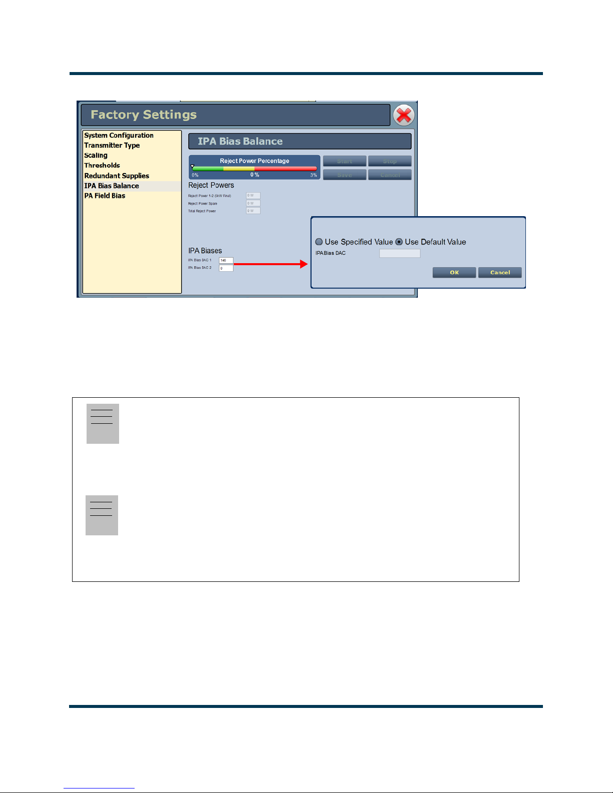
NV30/NV40 Operations and Maintenance Manual Operating the transmitter
IPA Bias DAC 1 = Module 1
IPA Bias DAC 2 = Module 2
Figure 2.49: Factory Settings - IPA Bias Balance
Note:
The IPA Bias Balance function targets the lowest possible total transmitter reject power. However,
there is no guarantee that it will achieve less than a specific amount. Variables such as RF module
output power and phase differences result in system reject power that can sometimes not be
compensated for with this function.
Note:
The Reject Power Percentage meter is only available in this functional menu. The green/amber/
red colours are simply to provide user feedback as to the progress of the function. If the transmitter
is operating normally, without fault, and the total reject power percentage falls within the amber
or red "post" an IPA bias balance routine, there is nothing to be concerned with, the function is
simply not able to completely compensate for the reject power (phase/amplitude differences).
Page 2-68 Issue 3.3 2014-12-10
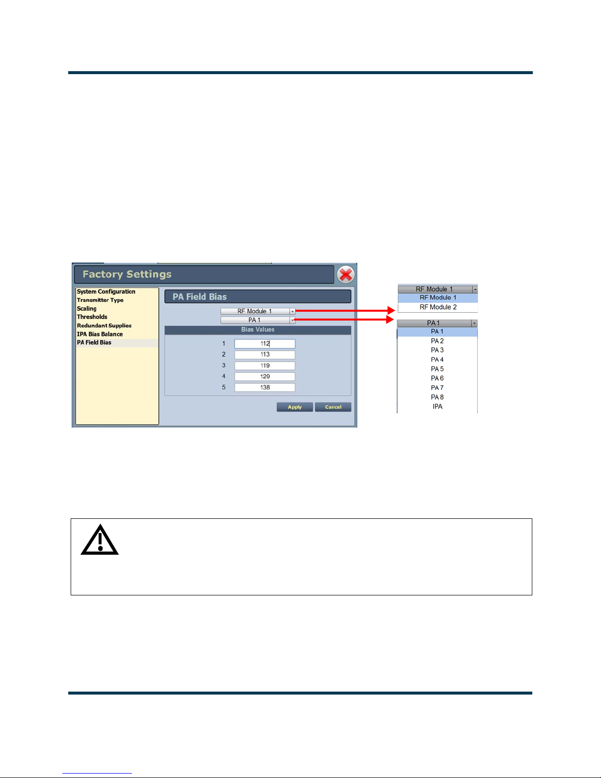
NV30/NV40 Operations and Maintenance Manual Operating the transmitter
PA field bias
This factory setting (see Figure 2.50) allows the user to easily set the applicable bias values from the
control tag provided with the replacement PA.
Select which RF Module and PA position the replacement PA was installed in, then enter the Bias
Valu es
The Bias Values fields accept only a decimal number format. Enter the decimal number from the
control tag, or if your spare PA control tag specifies a hexadecimal number, convert it to decimal and
then enter the appropriate decimal number.
Figure 2.50: Factory Settings - PA Field Bias
for indices 1 through 5 from the factory supplied control tag.
WARNING: Device settings are established at the factory and should not
require any adjustment. These settings affect critical system protection
circuits. Making changes to these settings may void your warranty.
Contact Nautel before making changes.
Issue 3.3 2014-12-10 Page 2-69
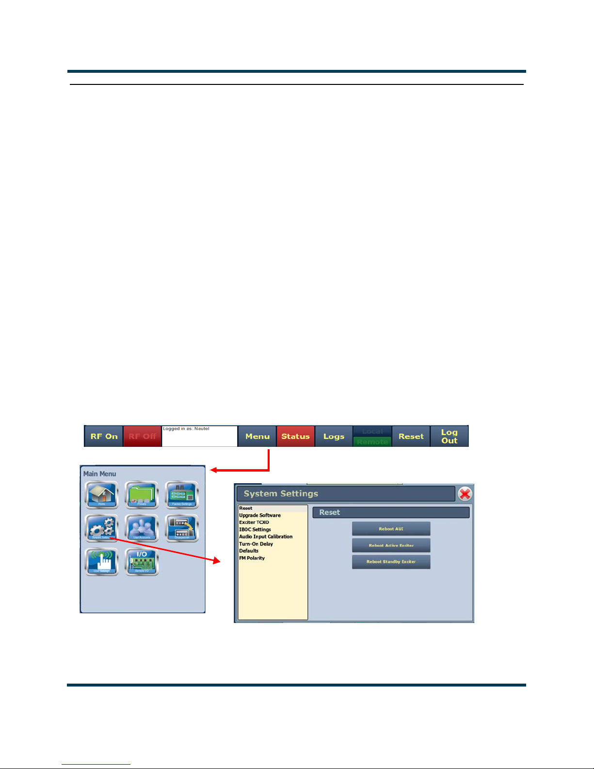
NV30/NV40 Operations and Maintenance Manual Operating the transmitter
System Settings
Users determine critical system configuration parameters via the System Settings page (see
Figure 2.51), which you access from the
This section includes the following topics:
• Reset on page 2-71
• Upgrade software on page 2-72
• Exciter TCXO on page 2-73
• IBOC settings on page 2-73
• Audio input calibration on page 2-75
• Turn-on delay on page 2-76
• Defaults on page 2-76
Menu page.
• FM polarity on page 2-78
Figure 2.51: System Settings Page
Page 2-70 Issue 3.3 2014-12-10

NV30/NV40 Operations and Maintenance Manual Operating the transmitter
Reset
The Reset page (see Figure 2.52) allows users to reboot three items - the AUI, the active exciter and
the standby exciter (if installed).
Figure 2.52: System Settings - Reset
Procedure to reset the AUI or either Exciter:
1. Select the Reset option from the left-side of the System Settings page to open a related
window on the right-side of the page.
2. Reset the items by pressing the appropriate key.
• To reset the AUI (advanced user interface), press
• To reset the active exciter press Reboot Active Exciter
• To reset the standby exciter press Reboot Standby Exciter.
After rebooting the AUI, users will need to log back into the transmitter AUI once again (see Logging
into the AUI on page 2-3). If the active exciter is rebooted, the transmitter’s RF power will be
interrupted if in RF On mode but the AUI will not be reset. If the standby exciter is rebooted, the
transmitter’s RF power will not be interrupted if in
RF On mode, nor will the AUI be reset.
Reboot AUI.
Issue 3.3 2014-12-10 Page 2-71

NV30/NV40 Operations and Maintenance Manual Operating the transmitter
Upgrade software
The Upgrade Software page allows for uploading a suite of software upgrade files (.tgz files) via
remote connection. Navigate the page as described below. Please note that users cannot add upgrade
files via the local AUI touchscreen. For additional information on loading software, see Upgrading
software on page 4-1 of this manual.
Figure 2.53: System Settings - Upgrade Software (Remote Upgrade Shown)
Select the Upgrade Software option from the left-side of the System Settings page to open a
related window on the right-side of the page. The page consists of the following sections and buttons:
• Current Version - indicates the current software version.
• Select Upgrade File - displays the available upgrade files uploaded to the transmitter.
• Details - opens a window containing information about the installed software. If an upgrade
file is selected, the screen will show a comparison between the installed version and the
selected upgrade by component. Identical versions are shown in green; different versions are
shown in red. You can also view the details of the previous upgrade by pressing the View
Last Upgrade
checkbox.
• History - displays a window containing a history of the upgrades to the software. Press the
+ button to maximize the details of the software. You can save this information to disk as a
.txt file from the remote AUI.
Start Upgrade - begins the process of upgrading the current software with the selected
•
upgrade file.
•
Manage Files (available through the remote AUI only) - opens a window displaying the files
you can upload to upgrade the software. You can add or delete files from this list using the
Browse, Upload and Delete buttons in the window.
Page 2-72 Issue 3.3 2014-12-10

NV30/NV40 Operations and Maintenance Manual Operating the transmitter
TWO TABS
SHOWN FOR
DUAL EXCITERS
Exciter TCXO
This system setting allows users to calibrate the internal clock to a user supplied external high
precision 10MHz clock reference (e.g. GPS synchronized 10MHz clock). Once this external 10MHz
clock reference is connected, the 10MHz Int-Ext Offset field will display the difference between the
internal and external frequencies (in ppm). Users can press the Start button to automatically calibrate
the internal TCXO to the external reference source; equally, they can manually enter the measured
internal-external offset value into the TCXO Offset Value field and press Apply.
If no external high precision 10MHz clock reference is connected, but the actual transmitter carrier
frequency is being measured with a calibrated external frequency counter, operators can manually
offset the internal TCXO by entering the appropriate ppm difference in the TCXO Offset Value field.
For example, if the frequency of the transmitter is 1 ppm too high, then a positive 1 ppm should be
entered in the TCXO Offset Value field in order to compensate. Similarly, if the transmitter frequency
is too low, enter a negative ppm value. After an adjustment is made, press Apply.
For dual exciters, two tabs appear (Exciter A and Exciter B) to allow calibration of each exciter.
Figure 2.54: System Settings - Exciter TCXO
IBOC settings
This system setting (see Figure 2.55 on page 2-74) allows users to establish Forward Tap Delay,
FM+HD Low Inj Gain, FM+HD High Inj Gain and HD only system Gain levels. It also allows for
an IBOC power calibration. Changes apply to the active exciter (A or B) only. To calibrate the other
exciter, switch to the other exciter and repeat the change.
Issue 3.3 2014-12-10 Page 2-73

NV30/NV40 Operations and Maintenance Manual Operating the transmitter
• Forward Tap Delay - This field displays the time delay (in unit taps) between the forward
path signal from the exciter and the reverse path signal into the exciter, fed back from the
output of the transmitter. This value is factory adjusted (to synchronize the phase of the forward and reverse signals so that pre-correction can operate properly) and should not require
any adjustment in the field.
• Auto-Find Gain - Press the Start button to automatically find the optimized gain while the
transmitter is RF On and in the applicable preset mode/injection level.
• FM+HD Low Inj Gain - Applicable for FM+HD mode only (at -20dBc to -15.1dBc injection
levels) and represents the starting/default gain applied to the forward path signal within the
exciter at initial turn on/ramp-up.
•FM+HD High Inj Gain - Applicable for FM+HD mode only (at -15dBc to -10dBc injection
level) and represents the starting/default gain applied to the forward path signal within the
exciter at initial turn on/ramp-up.
•HD Gain - Applicable for HD mode only and represents the starting/default gain applied to
the forward path signal within the exciter at initial turn on/ramp-up.
•IBOC Power Calibration - This calibration occurs at the factory and should not require any
adjustment in the field. This calibration is performed in FM mode.
• Calibration Value - This field displays the calibration of the exciter’s measurement of the
transmitter power.
Figure 2.55: System Settings - IBOC Settings
Page 2-74 Issue 3.3 2014-12-10

NV30/NV40 Operations and Maintenance Manual Operating the transmitter
Audio input calibration
This system setting (see Figure 2.56) supports the calibration of analog and MPX (composite) audio
inputs. The peak meter value of each calibrated audio input (
MPX Peak, MPX SCA Peak, Int. SCA1 Peak and Int. SCA2 Peak) will be displayed (when the
associated audio input source is connected). Enter the calibration value and press Apply to save
changes. Changes apply to the active exciter (A or B) only. To calibrate the other exciter, switch to the
other exciter and repeat the calibration.
Figure 2.56: System Settings - Audio Input Calibration
Analog Left Peak, Analog Right Peak,
Note:
Audio inputs are factory set using a high accuracy source and do not typically require user
adjustment. Changes to factory calibrations could cause low or excessive modulation and
noncompliance to strict regulatory limits
Issue 3.3 2014-12-10 Page 2-75

NV30/NV40 Operations and Maintenance Manual Operating the transmitter
Turn-on delay
This system setting (see Figure 2.57) allows users to delay the start-up (RF on) of the transmitter
when recovering from an ac power loss, in order to limit the simultaneous power demand from
multiple transmitters on a common generator by staggering their turn on sequence. Enter a value in
the allowable range of 0-120 seconds, defaulted to 0 seconds (disabled).
Figure 2.57: Turn-On Delay
Defaults
The Defaults page stores the default settings for RF module IPA bias and PA bias (see Figure 2.58
on page 2-77) as a function of mode (Bias tab). It also stores the default Exciter power level based on
transmitter type and default IPA output power (referenced to 98MHz) via the Power tab (see
Figure 2.59 on page 2-77). These settings are fixed and should require no adjustment by the user.
The transmitter RF modules store bias values in EEPROM that are pre-determined at the factory for
optimal operation of the IPA and PAs for each available mode. These varying levels of bias values
are stored in indexes 1 through 5, with index 0 having 0 bias stored (0 being the lowest amount of
bias, 5 being the highest). The IPA and PA index values are set based on the bias requirements of
each mode.
Note:
The transmitter automatically adjusts the actual IPA Power set-point based on the preset
frequency (as a function of a pre-determined frequency response), with the reference power level
value being at 98MHz.
Page 2-76 Issue 3.3 2014-12-10

NV30/NV40 Operations and Maintenance Manual Operating the transmitter
Figure 2.58: Defaults - Bias (IPA and PA default index values shown)
Figure 2.59: Defaults - Power
Note:
Default Exciter Power is transmitter specific; NV3.5/NV5 = 11W; NV7.5/NV10 = 25W;
NV15/NV20 = 65W and NV30/NV40 = 130W.
Default IPA Power at 98MHz is 110W.
These values are factory determined and should not require adjustment. These values apply for FM
mode only.
Issue 3.3 2014-12-10 Page 2-77

NV30/NV40 Operations and Maintenance Manual Operating the transmitter
FM polarity
This system setting (see Figure 2.60) allows users to invert the polarity of the frequency
modulation; (i.e. positive going modulation signal yields positive deviation; or positive going
modulation signal yields negative deviation). Options are Normal (default) or Inverted.
Figure 2.60: FM Polarity
Page 2-78 Issue 3.3 2014-12-10

NV30/NV40 Operations and Maintenance Manual Operating the transmitter
User accounts
Depending on user permission rights, you can set up accounts to allow certain users to access and
control features of the AUI using the User Accounts page - see Figure 2.61. To view the
Accounts
This section includes the following topics:
page, select User Accounts from the Menu options.
Note:
Depending on the permission level assigned to a given user, some features shown in Figure 2.61
may not be displayed or available.
• Setting user permission level on page 2-80
• Editing account information on page 2-80
User
Figure 2.61: User Accounts page
Issue 3.3 2014-12-10 Page 2-79

NV30/NV40 Operations and Maintenance Manual Operating the transmitter
Setting user permission level
There are four levels of permission that can be assigned to users, each with their own specific
function. All users have permission to change their own username and password, but are otherwise
limited to the following functions:
• View Only: Can monitor equipment data only. No administrative or control functions.
• Full Control: Can monitor and control equipment, with no administrative functions.
• Administrator: Can perform all functions. Administrator is the only permission level that
allows addition, removal or modification of users.
• Custom: Administrator can customize the user permissions by manually selecting the per-
mission levels.
Editing account information
Adding an account
You must be an Administrator to use this function.
Procedure to add a user (see Figure 2.62 on page 2-82):
1. Open the User Accounts page.
2. Press Add (bottom of the screen) to open a small Add User window.
3. Beside Username, enter a name that identifies the new user, and press OK.
4. Select the new user to edit the settings.
5. Beside
you select Custom as the type of user, then go to the Permissions section of the screen and
mark individual permissions (see Changing permissions on page 2-81).
6. Press Apply to confirm your entries and create a new user or press Cancel to ignore your
entries and exit the small window without creating a new user.
Editing an existing account
To edit an existing user account, press on the desired user in the Users list on the left-side of the AUI.
The
Settings for that user will be displayed on the right-hand side of the AUI. You can edit the
Password, User Type (see Setting user permission level above), Auto Login status and Permissions.
User Type, press the arrow to reveal a drop-down menu and select a type of user. If
Page 2-80 Issue 3.3 2014-12-10

NV30/NV40 Operations and Maintenance Manual Operating the transmitter
Changing the password
To change your password, press the Change Password button. A menu appears that prompts you to
enter the old password, new password and confirmation of the new password. Press Apply to save or
Cancel to exit this menu (see Figure 2.62 on page 2-82).
Setting auto login (local only) status
When checked (
) the selected user account will be automatically logged in to the transmitter with all
the rights and priveleges that have been assigned to that user. There may only be one autologin user at
any given time; when the Auto Login check box is selected for one user account, it is automatically
cleared on all other users. When not checked, the transmitter will not login automatically and will
instead prompt for username and password when it boots up. It should be noted that only accounts
with Administrator level permissions can set or remove Auto Login status.
Changing permissions
You must be an Administrator to edit this function.
All users have permission to change their own username and password. You can customize the
permissions assigned to a user or simply pick a predetermined set of permissions based on the user
type.
Procedure to change user permissions (see Figure 2.62 on page 2-82):
1. Open the User Accounts page.
2. Select a user from the Users list to display the permissions for that user in the center of the
Permissions window. The permissions associated with the selected user are identified with a
checkmark ().
3. Press on User Type to reveal a drop-down menu and select a new type of user.
4. If the user type in step 3 is
checkmark (
) beside each permission that you want to associate with the user. The boxes
Custom, set individual permissions. Under Permissions, place a
work like a toggle - select the checkbox to place a checkmark and select again to remove the
checkmark. Choose one or more of the following options:
Activate/Modify Preset - Allows the user to modify presets and change the active preset.
•
•
Power Control - Allows the user to change the power set point of the transmitter..
• Delete Logs - Allows the user to remove log entries.
RF On/Off - Allows the user to turn the RF output on and off..
•
Issue 3.3 2014-12-10 Page 2-81
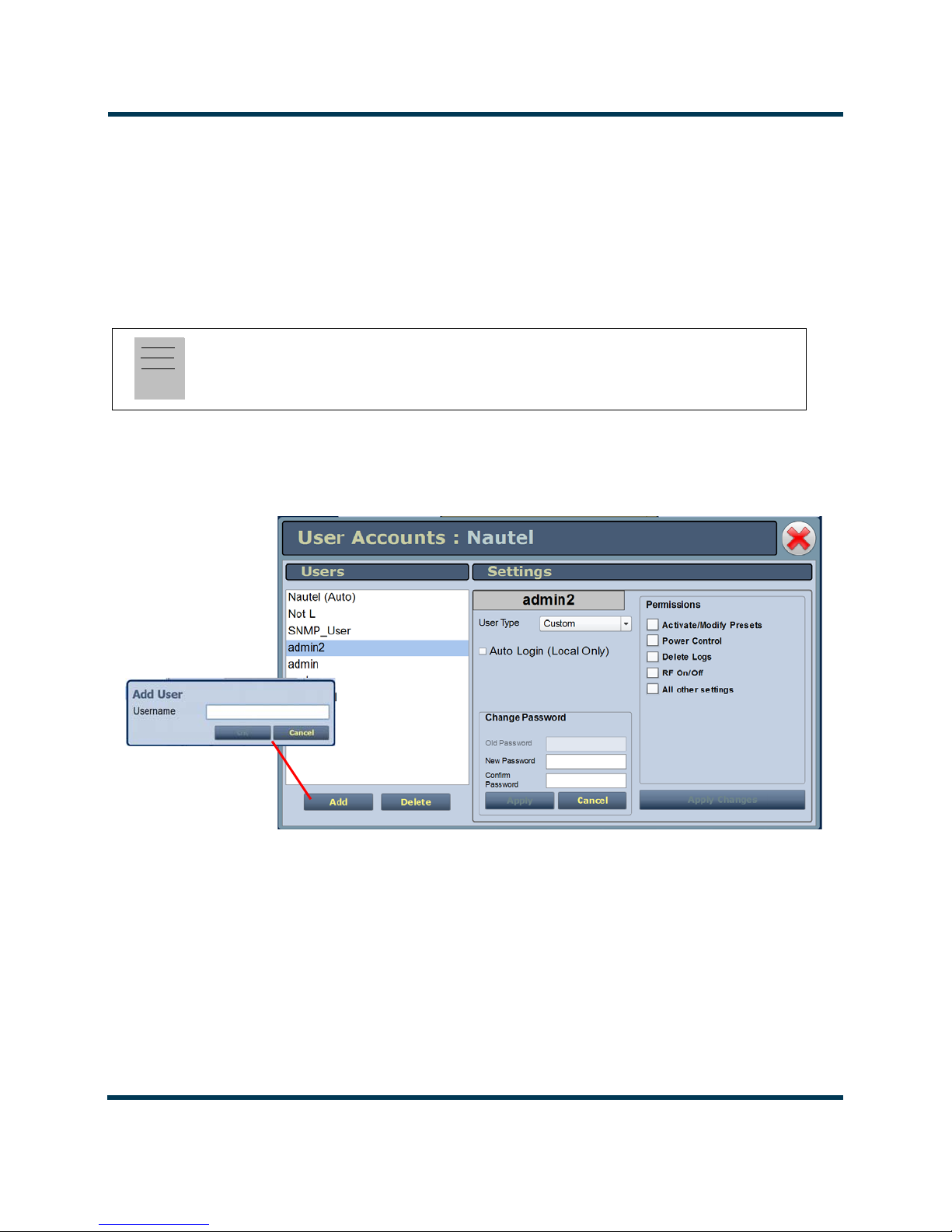
NV30/NV40 Operations and Maintenance Manual Operating the transmitter
• All Other Settings - Allows the user to adjust all settings not mentioned above, except for
administrating user accounts.
5. Press Apply to assign the new permissions to the selected user.
Removing an account
To remove a user account, select the desired user from the Users list and press the Delete button. A
verification prompt will appear. Press Ye s to proceed or No to cancel the deletion.
Note:
Do not delete the SNMP_User account from the list of users.
Figure 2.62: User Accounts Page Layout
Page 2-82 Issue 3.3 2014-12-10
 Loading...