

Page 1

TECHNICAL INSTRUCTIONS
FM10
FM BROADCAST TRANSMITTER
10 000 WATT
3-Phase AC Power
Original Issue
Change 1
Change 2
e-mail: [email protected]
.........................
.....................
........................
web: www.nautel.com
15 November 1999
15 July 1997
01 October 2002
Nautel Maine Inc. Nautel Limited
201 Target Industrial Circle, Hackett’s Cove, RR #1 Tantallon,
Bangor, Maine USA 04401 Nova Scotia Canada B0J 3J0
Phone: (207) 947-8200 Phone: (902) 823-3900
Fax: (207) 947-3693 Fax: (902) 823-3183
ISO 9002 REGISTERED ISO 9001 REGISTERED
© Copyright 2002 NAUTEL. All rights reserved
Page 2

10 000 WATT FM BROADCAST TRANSMITTER
FM10
LIST OF EFFECTIVE PAGES
The list of effective pages lists the status of all pages in this manual. Original pages are identified by a zero in the
Change No. column. Pages subsequently changed are identified by the date of the change number. On a changed
page, the text affected by the latest change is indicated by a vertical bar in the margin opposite the changed material.
Original
Change 1
Change 2
...........................................................
..............................................
..................................................
15 July 1997
15 November 1999
01 October 2002
Total number of printed sides in this manual is 198 as listed below:
CHANGE CHANGE
PAGE No. DATE PAGE No. DATE
Title 2 01 October 2002
Title (Rear) - Blank
Effective (1) 2 01 October 2002
Effective (2) 2 01 October 2002
Effective (3) 2 01 October 2002
Effective (4) - Blank
Safety (1) 2 01 October 2002
Safety (2) 2 01 October 2002
Safety (3) 2 01 October 2002
Safety (4) 2 01 October 2002
Warranty (1) 2 01 October 2002
Warranty (2) 2 01 October 2002
Contents (1) 0 15 July 1997
Contents (2) 0 15 July 1997
Contents (3) 0 15 July 1997
Contents (4) 0 15 July 1997
Contents (5) 0 15 July 1997
Contents (6) 0 15 July 1997
Contents (7) 0 15 July 1997
Contents (8) 1 15 November 1999
Contents (9) 1 15 November 1999
Contents (10) 1 15 November 1999
1-1 0 15 July 1997
1-2 0 15 July 1997
1-3 0 15 July 1997
1-4 0 15 July 1997
1-5 0 15 July 1997
1-6 0 15 July 1997
2-1 0 15 July 1997
2-2 2 01 October 2002
2-3 0 15 July 1997
2-4 0 15 July 1997
2-5 2 01 October 2002
2-6 0 15 July 1997
2-7 0 15 July 1997
2-8 0 15 July 1997
2-9 0 15 July 1997
2-10 1 15 November 1999
2-11 2 01 October 2002
2-12 0 15 July 1997
2-13 2 01 October 2002
2-14 2 01 October 2002
2-15 0 15 July 1997
2-16 0 15 July 1997
2-17 0 15 July 1997
2-18 - Blank
3-1 0 15 July 1997
3-2 0 15 July 1997
3-3 0 15 July 1997
3-4 0 15 July 1997
3-5 0 15 July 1997
3-6 0 15 July 1997
3-7 0 15 July 1997
3-8 0 15 July 1997
3-9 0 15 July 1997
3-10 0 15 July 1997
3-11 0 15 July 1997
3-12 0 15 July 1997
3-13 0 15 July 1997
3-14 0 15 July 1997
3-15 0 15 July 1997
3-16 0 15 July 1997
3-17 0 15 July 1997
3-18 0 15 July 1997
3-19 0 15 July 1997
3-20 0 15 July 1997
4-1 0 15 July 1997
4-2 0 15 July 1997
Effective Pages (Page 1)
01 October 2002
Page 3

10 000 WATT FM BROADCAST TRANSMITTER
FM10
LIST OF EFFECTIVE PAGES
CHANGE CHANGE
PAGE No. DATE PAGE No. DATE
4-3 0 15 July 1997
4-4 2 01 October 2002
4-5 2 01 October 2002
4-6 2 01 October 2002
5-1 0 15 July 1997
5-2 0 15 July 1997
5-3 0 15 July 1997
5-4 0 15 July 1997
5-5 0 15 July 1997
5-6 0 15 July 1997
5-7 0 15 July 1997
5-8 0 15 July 1997
5-9 0 15 July 1997
5-10 0 15 July 1997
5-11 2 01 October 2002
5-12 2 01 October 2002
5-13 2 01 October 2002
5-14 0 15 July 1997
5-15 0 15 July 1997
5-16 0 15 July 1997
5-17 0 15 July 1997
5-18 0 15 July 1997
5-19 0 15 July 1997
5-20 0 15 July 1997
5-21 0 15 July 1997
5-22 0 15 July 1997
5-23 0 15 July 1997
5-24 0 15 July 1997
5-25 0 15 July 1997
5-26 0 15 July 1997
5-27 0 15 July 1997
5-28 0 15 July 1997
5-29 0 15 July 1997
5-30 0 15 July 1997
5-31 2 01 October 2002
5-32 0 15 July 1997
6-1 0 15 July 1997
6-2 0 15 July 1997
6-3 0 15 July 1997
6-4 0 15 July 1997
6-5 0 15 July 1997
6-6 0 15 July 1997
6-7 0 15 July 1997
6-8 0 15 July 1997
6-9 1 15 November 1999
6-10 1 15 November 1999
6-11 0 15 July 1997
6-12 0 15 July 1997
(Continued)
7-1 0 15 July 1997
7-2 0 15 July 1997
7-3 0 15 July 1997
7-4 0 15 July 1997
7-5 0 15 July 1997
7-6 0 15 July 1997
7-7 0 15 July 1997
7-8 - Blank
8-1 0 15 July 1997
8-2 0 15 July 1997
8-3 0 15 July 1997
8-4 0 15 July 1997
8-5 0 15 July 1997
8-6 0 15 July 1997
8-7 0 15 July 1997
8-8 0 15 July 1997
8-9 0 15 July 1997
8-10 0 15 July 1997
8-11 0 15 July 1997
8-12 0 15 July 1997
8-13 0 15 July 1997
8-14 1 15 November 1999
8-15 2 01 October 2002
8-16 0 15 July 1997
8-17 0 15 July 1997
8-18 0 15 July 1997
8-19 1 15 November 1999
8-20 2 01 October 2002
8-21 2 01 October 2002
8-22 0 15 July 1997
8-23 2 01 October 2002
8-24 2 01 October 2002
8-25 1 15 November 1999
8-26 2 01 October 2002
8-27 1 15 November 1999
8-28 1 15 November 1999
9-1 1 15 November 1999
9-2 0 15 July 1997
9-3 1 15 November 1999
9-4 1 15 November 1999
9-5 1 15 November 1999
9-6 1 15 November 1999
9-7 1 15 November 1999
9-8 0 15 July 1997
9-9 1 15 November 1999
9-10 2 01 October 2002
Effective Pages (Page 2)
01 October 2002
Page 4

10 000 WATT FM BROADCAST TRANSMITTER
FM10
LIST OF EFFECTIVE PAGES
CHANGE CHANGE
PAGE No. DATE PAGE No. DATE
9-11 0 15 July 1997
9-12 0 15 July 1997
9-13 0 15 July 1997
9-14 0 15 July 1997
9-15 0 15 July 1997
9-16 0 15 July 1997
9-17 0 15 July 1997
9-18 0 15 July 1997
9-19 0 15 July 1997
9-20 0 15 July 1997
9-21 0 15 July 1997
9-22 - Blank
10-1 0 15 July 1997
10-2 0 15 July 1997
10-3 0 15 July 1997
10-4 - Blank
SD-1 0 15 July 1997
SD-2 2 01 October 2002
SD-3 0 15 July 1997
SD-4 2 01 October 2002
SD-5 0 15 July 1997
SD-6 0 15 July 1997
(Continued)
SD-7 0 15 July 1997
SD-8 0 15 July 1997
SD-9 0 15 July 1997
SD-10 0 15 July 1997
11-1 0 15 July 1997
11-2 1 15 November 1999
MD-1 0 15 July 1997
MD-2 0 15 July 1997
MD-3 1 15 November 1999
MD-4 0 15 July 1997
MD-5 0 15 July 1997
MD-6 0 15 July 1997
MD-7 1 15 November 1999
MD-8 0 15 July 1997
MD-9 0 15 July 1997
MD-10 0 15 July 1997
MD-11 0 15 July 1997
MD-12A 0 15 July 1997
MD-12B 0 15 July 1997
MD-13 1 15 November 1999
MD-14 0 15 July 1997
MD-15 0 15 July 1997
Effective Pages (Page 3)
01 October 2002
Page 5

10 000 WATT FM BROADCAST TRANSMITTER
ARTIFICIAL RESPIRATION (MOUTH-TO-MOUTH)
(a) START MOUTH-TO-MOUTH BREATHING
IMMEDIATELY. SECONDS COUNT.
loosen clothing, warm the casualty, or apply stimulants.
Do not wait to
FM10
1
(b) ASSESS RESPONSIVENESS OF CASUALTY
jar casualty or cause further physical injury (
(c) IF POSSIBLE, SEND A BYSTANDER TO GET
MEDICAL HELP.
(
Figure 2)
(d) CHECK CAROTID PULSE (
(e) LAY CASUALTY ON HIS/HER BACK
available jacket or blanket under his/her shoulders.
(f) TILT THE HEAD BACK AND LIFT THE CHIN
airway (
(g) PINCH CASUALTY’S NOSE AND EXHALE TWO SLOW
BREATHS INTO CASUALTY (
(h) REMOVE YOUR MOUTH
Figure 4)
Do not leave casualty unattended
Figure 3)
and place any
Figure 5)
and check for breathing
. Do not
Figure 1)
to open the
(Figure 6)
(i) CONTINUE GIVING ONE BREATH EVERY FIVE
SECONDS
the stomach after exhalation by casualty, press gently on
stomach to expel air.
without interruption. If any air is retained in
2
3
4
(j) IF CHEST DOES NOT RISE CHECK
casualty’s mouth: clear foreign material using your finger,
tissues, etc. Use chin lift and recommence mouth-tomouth breathing.
(k) WHILE MOUTH-TO-MOUTH BREATHING IS
CONTINUED
(a) Loosen casualty’s clothing.
(b) Keep the casualty warm.
(l) DON’T GIVE UP.
casualty is revived, or until a doctor pronounces the
casualty dead. Four hours or more may be required.
(m) DO NOT PROVIDE ANYTHING ORALLY
unconscious.
have someone else:
Continue without interruption until the
for obstruction in
5
6
while victim is
Safety (Page 1)
01 October 2002
Page 6

10 000 WATT FM BROADCAST TRANSMITTER
FM10
GENERAL RULES FOR TREATMENT FOR BURNS, BLEEDING, AND SHOCK
1. After casualty has revived, treat for injuries and shock.
2. Reassure casualty.
3. Try to make him comfortable.
4. Keep him reasonably warm but do not apply heat.
5. If thirsty, liquids may be given but no alcohol (no liquids should be given in cases of severe burns).
6. Treat burns or wounds. Infection danger in treating burns or wounds is very great so ensure hands are
clean and do not handle affected areas more than necessary.
7. Do not apply salves, grease, etc. to burns.
8. Do not remove burned clothing which adheres to the skin or break blisters.
9. Cover the burn with a dry sterile dressing, piece of sheeting, etc.
10. Bandage lightly over blisters where care must be taken to cover and not to break.
11. If severe bleeding of wound, elevate affected area, except in the case of a fracture.
12. Expose wound and apply pressure.
13. Apply dressing, pad and bandage.
14. For burns and bleeding, immobilize injured part using splints if necessary and keep patient in restful
position during removal to hospital or expert medical attention.
15. In all cases, send for medical aid immediately.
Safety (Page 2)
01 October 2002
Page 7

10 000 WATT FM BROADCAST TRANSMITTER
FM10
ELECTRIC SHOCK - RESCUE METHODS
Electricity can damage the body in a number of ways. It may interfere with the proper functioning of the nervous
system and the heart action, it can subject the body to extreme heat and can cause severe muscular contractions.
The path that the current of electricity takes through the body is important. Currents which pass from hand to hand
or from hand to foot may pass directly through the heart and upset its normal functioning. This threat to life is
related to the amount of current or amperage that will flow through a victim's body. Very little current (as little as
10 milliamps) can result in severe shock or death.
Speed in the application of first aid measures is absolutely essential in cases of electrical injury. As soon as the
victim is freed safely from the source of the electrical current, if breathing has stopped, artificial respiration should
be commenced immediately. If the carotid pulse cannot be felt, external cardiac massage should be commenced
simultaneously. Resuscitation should be continued until the patient is breathing on his own or until medical aid
arrives. Survival rates can be quite high if cardio-pulmonary resuscitation is started within 3 to 4 minutes of the
injury being received.
ACT AT ONCE - DELAY OR INDECISION MAY BE FATAL
1. Turn
the electrical source.
OFF
2. Commence artificial respiration immediately.
3. Treat for burns, bleeding and shock.
REMOVING A CASUALTY FROM ELECTRICAL CONTACT
LOW VOLTAGE - 0 to 240 volts (household use)
Switch off the current, if possible and time permits. If the switch cannot be located immediately and the supply is
through a flexible cord or cable, the current may be shut off by removing the plug or even breaking the cable or
wrenching free. Never attempt to shut off current by cutting cord with a knife or scissors.
If the current cannot be shut off, the greatest care is necessary in removing the casualty. Household rubber gloves,
rubber or plastic hose (if there is no water in them), a dry unpainted stick or a clean dry rope can be used to free
victim.
HIGH VOLTAGE - 240 volts and up (industrial machines and power lines)
Do not touch any person or equipment in contact with a wire.
Use a dry unpainted pole, clean dry rope, dry rubber or plastic water hose to separate the casualty from the contact.
Keep as far away as possible.
Do not touch the casualty until he is free.
Safety (Page 3)
01 October 2002
Page 8

10 000 WATT FM BROADCAST TRANSMITTER
FM10
TOXIC HAZARD WARNING
There are devices used in this equipment containing
BERYLLIUM OXIDE
ceramic, which is non-hazardous during
normal device operation and under normal device failure conditions. These devices are specifically identified in the
equipment manual’s parts list(s).
DO NOT
cut, crush or grind devices because the resulting dust may be
HAZARDOUS IF INHALED
.
Unserviceable devices should be disposed of as harmful waste.
Safety (Page 4)
01 October 2002
Page 9

10 000 WATT FM BROADCAST TRANSMITTER
FM10
WARRANTY
Nautel Limited/Nautel Maine Incorporated, hereinafter referred to as Nautel, guarantees all mechanical and
electrical parts of the equipment for a period of thirteen months from date of shipment.
1. A "Part Failure" shall be deemed to have occurred when the part has become defective, or does not have the
characteristics required for the specified equipment performance:
(a) When the equipment is operated within the design parameters, and
(b) When the equipment is installed and adjusted according to Nautel's prescribed procedures as stated in
the instruction manual.
2. Nautel shall provide replacements for all "Parts" at no cost to the Customer when they become defective
during the warranty period, and upon the return of the defective part.
3. In the event that a "Part" fails during the warranty period and causes damage to a sub-assembly that cannot
be readily repaired in the field, the entire sub-assembly so damaged may be returned to Nautel for repair.
The repairs will be made without charge to the Customer.
4. Where warranty replacements or repair are provided under items 2 or 3, Nautel will pay that part of the
shipping costs incurred in returning the part/assembly to the Customer.
5. Warranty replacement parts and repair, which are provided under items 2 or 3, shall be guaranteed for a
period of ninety days from date of shipment or until the end of the original warranty period, whichever occurs
later.
6. Nautel will not assume responsibility for any charges incurred by other than Nautel employees.
7. Nautel shall have the privilege of investigating whether failures have been caused by factors beyond its
control.
8. Nautel shall in no event be liable for any consequential damages arising from the use of this equipment.
9. When requesting a warranty repair/replacement, please provide complete and accurate information. Observe
the instructions regarding 'Equipment Being Returned to Nautel' on page two of this warranty and provide the
information requested.
10. When ordering spare/replacement parts; please provide complete and accurate information. Refer to the parts
list of this manual for ordering information. Provide as much of the information requested for 'Equipment
Being Returned to Nautel' on page two of this warranty as is practical. The information identified by an
asterisk is the minimum required.
ON-LINE PART QUOTES
Nautel provides an on-line website service (www.nautel.com/in-service.html) where requests for part quotes may
be submitted. Requests will normally be responded to within one working day.
Warranty (Page 1)
01 October 2002
Page 10

10 000 WATT FM BROADCAST TRANSMITTER
FM10
FACTORY SUPPORT
TECHNICAL ASSISTANCE
Nautel's field service department provides telephone technical assistance on a 24 hour, seven days a week basis.
Requests by other media (facsimile or e-mail) will be responded to the next working day if received after Nautel's
normal working hours. Contact the appropriate field service centre from the following:
U.S.A. customers use:
All other customers use:
Nautel Maine Incorporated Telephone 207-947-8200 (24 hours)
201 Target Industrial Circle Facsimile 207-947-3693
Bangor, Maine 04401
Nautel Limited Telephone 902-823-3900 (24 hours)
10089 Peggy's Cove Road Facsimile 902-823-3183
Hackett's Cove, Nova Scotia E-Mail [email protected]
Canada Web
B3Z 3J4
www.nautel.com
MODULE EXCHANGE SERVICE
In order to provide Nautel customers with a fast and efficient service in the event of a problem, Nautel operates a
factory rebuilt, module exchange service which takes full advantage of the high degree of module redundancy in
Nautel equipment. This module exchange service is operated from Nautel’s factory in Bangor, Maine and
Hackett’s Cove, Nova Scotia. These two locations allow us to provide a quick turn around service to keep our
customers on the air. During the transmitter’s warranty period, up to thirteen months from shipment, repair and
exchange of modules is at no charge to the customer. When the warranty has expired, a charge of 80% of the
list price for all exchanged modules is made. If the faulty module is returned to Nautel within 30 days, a credit is
issued reducing this charge by one half to 40% of the list price. U.S.A. customers are required to contact our
Bangor, Maine facility. Canadian and overseas customers should contact our Nova Scotia, Canada facility.
EQUIPMENT BEING RETURNED TO NAUTEL
All equipment being returned to Nautel and all requests for repairs or replacements should be marked 'field
return' and addressed to the appropriate Nautel facility.
Complete and accurate information regarding the equipment being returned will ensure prompt attention and will
expedite the dispatch of replacements. Refer to the nameplate on the transmitter and/or the appropriate
module/assembly to obtain name, type, part and serial number information. Refer to the parts list of this manual
or the appropriate service instruction manual for additional ordering information.
The following information should accompany each request:
* Model of Equipment
* Serial number of Equipment
* Name of Part/Assembly
Serial number of Part/Assembly
* Complete reference designation of Part/Assembly
* Nautel's part number of Part/Assembly
* OEM's part number of Part/Assembly
Number of hours in Use
Nature of defect
* Return shipping address
* Denotes minimum information required to order spare/replacement parts
Warranty (Page 2)
01 October 2002
Page 11

10 000 WATT FM BROADCAST TRANSMITTER
FM10
TABLE OF CONTENTS
Section Page
1 GENERAL INFORMATION
1.1 INTRODUCTION
1.2 FACTORY SUPPORT
1.3 PURPOSE AND SCOPE OF MANUAL
1.3.1 FAMILY TREE
1.4 PURPOSE OF EQUIPMENT
1.5 MECHANICAL DESCRIPTION
1.6 TECHNICAL SUMMARY
1.7 SPECIAL TOOLS AND TEST EQUIPMENT
1.8 GLOSSARY OF TERMS
........................................................................................................
............................................................................................................
2 UNPACKING AND INSTALLATION
2.1 PLANNING AND SITE PREPARATION
2.1.1 TRANSMITTER ROOM REQUIREMENTS
2.1.1.1 Transmitter Dimensions
2.1.1.2 Transmitter Clearances
2.1.1.3 Air Flushing
2.1.1.4 Cooling
2.1.1.5 Heating
2.1.1.6 Work Area
2.1.2 LIGHTNING PROTECTION
2.1.2.1 Station Reference Ground
2.1.2.2 AC Power Source
2.1.2.3 Antenna Feed Cable
2.1.2.4 Antenna Tower
2.1.2.5 External Control/Monitor Wiring
2.1.3 ELECTRICAL POWER
2.1.3.1 Nominal Voltage
2.1.3.2 Voltage Stability
2.1.3.3 Power Consumption
2.1.3.4 External Switching
2.1.4 ANTENNA SYSTEM
2.1.4.1 RF Feed Cable
2.1.5 RF DRIVE SOURCE
2.1.6 SAFETY INTERLOCK
2.1.7 REMOTE CONTROL CIRCUITS
2.1.7.1 RF On Control
2.1.7.2 RF Off Control
2.1.7.3 Protection Reset
2.1.7.4 Power Increase
2.1.7.5 Power Decrease
2.1.7.6 Low Power Select
2.1.8 EXCITER INTERLOCK
2.1.9 RF PERFORMANCE MONITORING
2.1.9.1 Forward Power Level
2.1.9.2 Reflected Power Level
2.1.9.3 RF Output Sample
2.1.9.4 Exciter Power Sample
...........................................................................................................
.................................................................................................................
.................................................................................................................
............................................................................................................
......................................................................................................
....................................................................................................
.....................................................................................................
......................................................................................................
......................................................................................................
.....................................................................................................
....................................................................................................
................................................................................................
.......................................................................
......................................................................................
...................................................................................
............................................................................................
..............................................................
............................................................................................
.....................................................................
.................................................................
........................................................................................
.........................................................................................
........................................................................................
....................................................................................
.................................................................................................
.............................................................................................
............................................................................
...............................................................................................
...................................................................................................
..............................................................................................
................................................................................................
...................................................................................................
...................................................................................................
.................................................................................................
.................................................................................
...................................................................................................
.................................................................................................
...............................................................................................
...........................................................................
............................................................................................
..........................................................................................
................................................................................................
...........................................................................................
1-1
1-1
1-1
1-1
1-1
1-1
1-1
1-1
1-1
2-1
2-1
2-1
2-1
2-1
2-1
2-1
2-1
2-2
2-2
2-2
2-2
2-2
2-2
2-2
2-2
2-2
2-3
2-3
2-3
2-3
2-3
2-3
2-3
2-3
2-3
2-4
2-4
2-4
2-4
2-4
2-4
2-4
2-4
2-4
2-5
Contents (Page 1)
15 November 1999
Page 12

10 000 WATT FM BROADCAST TRANSMITTER
FM10
TABLE OF CONTENTS
(Continued)
Section Page
2 UNPACKING AND INSTALLATION
2.1.9.5 DC Input Current Level
2.1.9.6 DC Input Voltage Level
2.1.10 REMOTE ALARM INDICATIONS
2.1.10.1 IPA/RF Fail Alarm
2.1.10.2 PA/Module Fail Alarm
2.1.10.3 High Reflected Power Alarm
2.1.10.4 AC Power Alarm
2.1.10.5 High Temperature Alarm
2.1.10.6 PA Volts/Combiner Alarm
2.1.10.7 Interlock Open Alarm
2.1.10.8 Fan Fail Alarm
2.1.10.9 Low Battery Alarm
2.1.11 REMOTE STATUS INDICATIONS
2.1.11.1 Remote Status
2.1.11.2 RF On Status
2.1.11.3 Transmitter Ready Status
2.1.12 PARTS SUPPLIED BY NAUTEL
2.1.12.1 Parts Removed During Disassembly for Shipment
2.1.12.2 Ancillary Parts
2.1.13 PARTS REQUIRED BUT NOT SUPPLIED BY NAUTEL
2.1.13.1 Surge Protector Panel
2.1.14 TEST EQUIPMENT AND SPECIAL TOOLS
2.2 NON-TECHNICAL PRE-COMMISSIONING
2.2.1 ACCEPTANCE OF SHIPMENT
2.2.2 UNPACKING INSTRUCTIONS
2.2.3 ASSEMBLY/INSTALLATION
2.2.4 INSTALLATION OF EXTERNAL CONTROL/MONITOR WIRING
2.2.5 INSTALLATION OF AC POWER SUPPLY ASSEMBLY
2.2.6 INSTALLATION OF AC POWER SOURCE WIRING
2.2.7 IPA/RF POWER MODULE INSTALLATION
2.2.8 EXCITER INSTALLATION
2.2.8.1 Internally Mounted Nautel Exciter
2.2.8.2 Externally Mounted Exciter
2.2.9 RF OUTPUT ACCESS
2.2.10 INSTALLATION OF RF FEED CABLE
2.2.10.1 Connection of RF Feed Cable
2.2.11 REFERENCE GROUND INTERCONNECTION
2.3 TECHNICAL PRE-COMMISSIONING
2.3.1 SELECTING PWR TRANSFORMER'S PRIMARY WINDING TAPS
2.3.2 SELECTING EXCITER INTERLOCK CONNECTIONS
2.3.3 LOAD RESISTANCE CHECK FOR B+ VOLTAGE POWER SUPPLY
2.3.4 CONTROL/MONITOR BATTERY
2.3.5 REMOVAL OF METER SHORTING CLIPS
(Continued)
.........................................................................................
.........................................................................................
................................................................................
.................................................................................................
...........................................................................................
.................................................................................
...................................................................................................
.......................................................................................
.....................................................................................
............................................................................................
......................................................................................................
................................................................................................
..............................................................................
......................................................................................................
........................................................................................................
.....................................................................................
.................................................................................
................................................
.......................................................................................................
.............................................
...........................................................................................
...............................................................
................................................................
..................................................................................
...................................................................................
.......................................................................................
...............................
..............................................
................................................
..............................................................
........................................................................................
.......................................................................
.................................................................................
..............................................................................................
......................................................................
.............................................................................
........................................................
.......................................................................
.........................
..............................................
.......................
.............................................................................
..............................................................
2-5
2-5
2-5
2-5
2-5
2-5
2-6
2-6
2-6
2-6
2-6
2-6
2-6
2-6
2-7
2-7
2-7
2-7
2-7
2-7
2-7
2-7
2-8
2-8
2-8
2-8
2-8
2-9
2-10
2-11
2-13
2-13
2-13
2-14
2-14
2-14
2-14
2-16
2-16
2-16
2-16
2-16
2-17
Contents (Page 2)
15 November 1999
Page 13

10 000 WATT FM BROADCAST TRANSMITTER
FM10
TABLE OF CONTENTS
(Continued)
Section Page
3 CONTROLS AND INDICATORS
3.1 GENERAL
3.2 AC/DC POWER SUPPLY CONTROLS AND INDICATORS
3.3 CONTROL/MONITOR FUNCTIONS CONTROLS AND INDICATORS
3.4 RF POWER STAGE CONTROLS AND INDICATORS
3.5 RF POWER MODULE CONTROL AND INDICATORS
3.6 IPA MODULE CONTROL AND INDICATORS
..................................................................................................................
.......................................
...............................................
...............................................
............................................................
.......................
3-1
3-1
3-1
3-1
3-1
3-1
4 COMMISSIONING/OPERATION INSTRUCTIONS
4.1 GENERAL
4.2 CONTROLS AND INDICATORS
4.3 EMERGENCY SHUTDOWN PROCEDURE
4.3.1 TURN-OFF OF RF OUTPUT
4.3.2 COMPLETE SHUTDOWN
4.4 PRE-STARTUP CHECKS
4.5 TURNING ON THE TRANSMITTER
4.6 POWER AMPLIFIER MODULE CIRCUIT BREAKER SETTINGS
4.7 OPERATING PRECAUTIONS
4.8 READING FORWARD/REFLECTED POWER METER
4.9 REMOTE OPERATION
4.10 COMMISSIONING PROCEDURES
4.10.1 CONTROL/MONITOR BACKUP BATTERY INSTALLATION
4.10.2 EXCITER SETUP
4.10.3 PRELIMINARY SETTINGS
4.10.4 INITIAL TURN-ON
4.10.4.1 Low Voltage DC Power Supplies
4.10.4.2 Enabling of RF Power Circuits
4.10.4.3 Intermediate RF Power Check
4.10.4.4 Check of RF Power Stages
4.10.5 PUTTING TRANSMITTER IN SERVICE
..................................................................................................................
................................................................................
................................................................
......................................................................................
..........................................................................................
...........................................................................................
...........................................................................
....................................................................................
...............................................
..............................................................................................
............................................................................
......................................
........................................................................................................
.........................................................................................
......................................................................................................
...........................................................................
..............................................................................
..............................................................................
...................................................................................
.....................................................................
..............................
4-1
4-1
4-1
4-1
4-1
4-1
4-2
4-2
4-2
4-2
4-2
4-3
4-3
4-3
4-4
4-4
4-4
4-5
4-5
4-5
4-7
5 SYSTEM LEVEL TROUBLE SHOOTING
5.1 GENERAL
5.2 SCHEDULED MAINTENANCE
5.3 CORRECTIVE MAINTENANCE
5.3.1 ON-AIR TROUBLE SHOOTING
5.3.1.1 Remote Trouble Shooting
5.3.1.2 Local Trouble Shooting
5.3.2 OFF-AIR TROUBLE SHOOTING
5.4 ELECTROSTATIC PROTECTION
5.4.1 PERSONAL DISCHARGING
5.4.2 HANDLING/STORAGE
5.4.3 TOOLS/TEST EQUIPMENT
5.4.4 STRESS CURRENT PROTECTION
5.5 OPERATION WITH DEFECTIVE/MISSING RF POWER AMPLIFIER MODULES
5.6 RF POWER AMPLIFIER MODULE/IPA MODULE FAULT ISOLATION
5.6.1 POWER AMPLIFIER TROUBLE SHOOTING
..................................................................................................................
...................................................................................
..................................................................................
..................................................................................
.....................................................................................
.........................................................................................
................................................................................
..............................................................................
.......................................................................................
...............................................................................................
........................................................................................
...........................................................................
......
.....................
.............................................................
Contents (Page 3)
15 November 1999
5-1
5-1
5-1
5-1
5-1
5-2
5-2
5-2
5-2
5-2
5-2
5-3
5-3
5-4
5-5
Page 14

10 000 WATT FM BROADCAST TRANSMITTER
FM10
TABLE OF CONTENTS
(Continued)
Section Page
Continued)
5 SYSTEM LEVEL TROUBLE SHOOTING
5.7 REPLACEMENT OF RF POWER MODULE
5.7.1 RF POWER MODULE REMOVAL
5.7.2 RF POWER AMPLIFIER TUNING
5.7.2.1 Test Equipment For Tuning
5.7.2.2 Preparation For Tuning
5.7.2.3 Tuning Procedure
5.7.2.4 Completion of Tuning
5.7.3 RF POWER AMPLIFIER MODULE INSTALLATION
5.8 TEMPORARY REPLACEMENT OF IPA MODULE WITH RF POWER MODULE
5.8.1 RF POWER MODULE REMOVAL
5.8.2 IPA MODULE REMOVAL
5.8.3 IPA REPLACEMENT/RF POWER MODULE INSTALLATION
5.9 CONTROL/MONITOR PWB REPLACEMENT/ADJUSTMENT
5.10 POWER SUPPLY CONTROL PWB REPLACEMENT
5.11 TROUBLE SHOOTING FRONT PANEL ALARMS
5.11.1 PA FAIL ALARM
5.11.2 MODULE RF DRIVE ALARM
5.11.3 MODULE TEMP ALARM
5.11.4 AC PHASE ALARM
5.11.5 HIGH AC PWR ALARM
5.11.6 LOW AC PWR ALARM
5.11.7 REFLECTED POWER ALARM
5.11.7.1 Reflected and Forward Power Zero Watts
5.11.7.2 Reflected Power Zero Watts and Forward Power Normal
5.11.7.3 Reflected Power Between 100 and 440 Watts
5.11.8 IPA INPUT ALARM
5.11.8.1 Exciter ALC Check
5.11.8.2 Cables/Connections
5.11.8.3 RF Drive Checks
5.11.9 IPA OUTPUT ALARM
5.11.9.1 IPA Module Low Supply Voltage Check
5.11.9.2 IPA Module Replacement
5.11.9.3 Control/Monitor PWB IPA Output Monitor Check
5.11.10 IPA SWR ALARM
5.11.10.1 IPA Reflected Power
5.11.10.2 IPA Forward Power
5.11.11 IPA TEMP ALARM
5.11.12 PA VDC FAIL PWR SPLY (A thru F) ALARM
5.11.12.1 Low Supply Output
5.11.12.2 High Supply Output/High Supply Temp
5.11.13 PWR SPLY FAIL IPA ALARM
5.11.13.1 Low IPA Supply Output
5.11.13.2 High IPA Supply Output
5.11.14 FAN FAIL ALARM
5.11.15 RECTIFIER TEMPERATURE ALARM
5.12 AIR FILTERS
5.13 BACKUP BATTERY
5.14 REPLACEMENT OF COAXIAL CABLES
.......................................................................................................
...................................................................................................
...................................................................................................
.................................................................................................
.....................................................................................................
....................................................................................................
.....................................................................................................
............................................................................................................
.................................................................................................
(
...............................................................
..............................................................................
..............................................................................
...................................................................................
.........................................................................................
...............................................................................................
..........................................................................................
.................................................
.....
............................................................................
..........................................................................................
...................................
.................................
..............................................
...................................................
....................................................................................
...........................................................................................
............................................................................................
.............................................................................................
.................................................................................
...........................................................
....................................
.....................................................
..............................................................................................
............................................................................................
...............................................................................................
..............................................................
...................................................................................
................................................
...........................................................................................
.............................................................................................
............................................................
..............................................................................................
...............................................................
...................................................................................
.................................................................................
......................................................................................
......................................................................
.................................................................
5-6
5-6
5-7
5-8
5-8
5-10
5-12
5-12
5-13
5-13
5-13
5-14
5-15
5-16
5-19
5-19
5-19
5-20
5-21
5-21
5-22
5-22
5-22
5-23
5-23
5-24
5-24
5-24
5-24
5-25
5-25
5-25
5-25
5-25
5-25
5-26
5-26
5-27
5-27
5-27
5-28
5-28
5-28
5-28
5-29
5-29
5-29
5-29
Contents (Page 4)
15 November 1999
Page 15

10 000 WATT FM BROADCAST TRANSMITTER
FM10
TABLE OF CONTENTS
(Continued)
Section Page
6 THEORY OF OPERATION
6.1 GENERAL
6.2 TRANSMITTER DESCRIPTION
6.3 AC/DC POWER SUPPLY
6.3.1 POWER TRANSFORMER (A1T1)
6.3.2 THREE-PHASE RECTIFIER ASSEMBLIES (A2, A3)
6.3.3 CIRCUIT BREAKER PANEL
6.3.4 LOW VOLTAGE POWER SUPPLY ASSEMBLY (A26)
6.3.4.1 Low Voltage Power Supply PWB (A26A1)
6.3.4.1.1 -15V Regulator
6.3.4.1.2 +24V Fan Supply
6.3.4.1.3 +15V Regulator
6.3.4.1.4 +5V Regulator
6.3.4.2 3-Phase Monitor PWB
6.3.5 COOLING FANS
6.3.6 SWITCHING POWER SUPPLY (A THRU F AND IPA)
6.3.7 POWER SUPPLY CONTROL PWB (A5A1)
6.3.7.1 PA Volts Control
6.3.7.2 IPA Volts Control
6.3.7.3 Charging Relay Control
6.3.7.4 PA Volts Monitor
6.3.7.4.1 High PA Volts
6.3.7.4.2 Low PA Volts
6.3.7.5 IPA Volts Monitor
6.3.7.5.1 High IPA Volts
6.3.7.5.2 Low IPA Volts
6.3.7.6 Temperature Monitors
6.3.7.6.1 Switching Power Supplies
6.3.7.6.2 3-Phase Rectifier Assemblies
6.3.7.7 Fan Failure Detection
6.3.7.8 Switching Power Supply Module Inhibit
6.3.7.9 Alarm Reset
6.4 RF POWER STAGE
6.4.1 IPA INPUT POWER PROBE
6.4.2 INTERMEDIATE POWER AMPLIFIER (IPA) MODULE
6.4.3 INTERMEDIATE RF DRIVE SPLITTER
6.4.3.1 IPA Combiner
6.4.3.2 IPA Output Splitter
6.4.3.3 IPA SWR Probe
6.4.4 RF POWER MODULE
6.4.5 RF COMBINER/FINAL FILTER
6.4.6 RF POWER PROBE
6.5 CONTROL/MONITOR FUNCTION
6.5.1 CONTROL/DISPLAY PWB
6.5.2 CONTROL/MONITOR PWB
6.5.2.1 External Inputs
6.5.2.2 External Outputs
6.5.2.3 Local/Remote Control Selection
..................................................................................................................
.................................................................................
...........................................................................................
..............................................................................
..................................................
.......................................................................................
.............................................................
...............................................................................................
............................................................................................
..............................................................................................
................................................................................................
..........................................................................................
.........................................................................................................
................................................................
...................................................................................................
..................................................................................................
.........................................................................................
...................................................................................................
.................................................................................................
..................................................................................................
..................................................................................................
................................................................................................
.................................................................................................
...........................................................................................
...............................................................................
.........................................................................
............................................................................................
.................................................................
..........................................................................................................
...................................................................................................
......................................................................................
......................................................................
.......................................................................................................
................................................................................................
....................................................................................................
................................................................................................
...................................................................................
...................................................................................................
.............................................................................
.........................................................................................
.......................................................................................
......................................................................................................
...................................................................................................
............................................................................
...............................................
...............................................
..............................................
6-1
6-1
6-1
6-1
6-1
6-2
6-2
6-2
6-2
6-2
6-2
6-2
6-3
6-3
6-3
6-4
6-4
6-4
6-4
6-5
6-5
6-5
6-5
6-5
6-5
6-5
6-5
6-6
6-6
6-6
6-6
6-6
6-6
6-6
6-6
6-6
6-7
6-7
6-7
6-7
6-7
6-8
6-8
6-8
6-8
6-8
6-9
Contents (Page 5)
15 November 1999
Page 16

10 000 WATT FM BROADCAST TRANSMITTER
FM10
TABLE OF CONTENTS
(Continued)
Section Page
(Continued)
6 THEORY OF OPERATION
6.5.2.4 RF On/Off Control
6.5.2.5 Transmitter Interlock
6.5.2.6 Transmitter Output Power Level Adjustment
6.5.2.7 Automatic Level Control (ALC)
6.5.2.8 Alarm Reset
6.5.2.9 Protection Reset
6.5.2.10 Module Inhibit Reset
6.5.2.11 High RF Power Module Temperature
6.5.2.12 High IPA Temperature
6.5.2.13 Low RF Power Module RF Drive
6.5.2.14 PA Fail Alarm
6.5.2.15 Low IPA Module Input
6.5.2.16 High IPA Module Input
6.5.2.17 Low IPA Module Output
6.5.2.18 High IPA Module Output
6.5.2.19 High IPA Reflected Power
6.5.2.20 Low Transmitter Forward Power
6.5.2.21 Transmitter Reflected Power
6.5.2.21.1 Refld Pwr Less Than 100 Watts
6.5.2.21.2 Refld Pwr Greater Than 440 Watts
6.5.2.21.3 Refld Pwr Greater Than 1200 Watts
6.5.2.22 High AC Power
6.5.2.23 Low AC Power
6.5.2.24 AC Phase Failure
6.5.2.25 Battery Backup
.................................................................................................
.............................................................................................
.........................................................
............................................................................
........................................................................................................
.................................................................................................
.....................................................................................
............................................................
..................................................................................
...................................................................
...............................................................................................
...................................................................................
..................................................................................
................................................................................
...............................................................................
............................................................................
...................................................................
........................................................................
..........................................................................
.....................................................................
...................................................................
.............................................................................................
..............................................................................................
.........................................................................................
.............................................................................................
6-9
6-9
6-9
6-10
6-10
6-10
6-10
6-10
6-10
6-10
6-11
6-11
6-11
6-11
6-11
6-11
6-11
6-12
6-12
6-12
6-12
6-12
6-12
6-12
6-12
7 COMPONENT LEVEL TROUBLE SHOOTING
7.1 TROUBLE SHOOTING REFERENCE DATA
7.2 AC/DC POWER SUPPLY
7.2.1 SWITCHING POWER SUPPLIES
7.2.2 POWER SUPPLY CONTROL PWB
7.2.3 LOW VOLTAGE POWER SUPPLY PWB
7.2.4 3-PHASE MONITOR PWB
7.3 RF POWER STAGE
7.3.1 RF POWER MODULES
7.3.2 INTERMEDIATE POWER AMPLIFIER MODULE
7.4 CONTROL/MONITOR FUNCTION
7.4.1 CONTROL/MONITOR PWB
8 PARTS LIST
8.1 INTRODUCTION
8.2 FAMILY TREE
8.3 MANUFACTURER'S INDEX
8.4 HOW TO LOCATE INFORMATION FOR A SPECIFIC PART
8.4.1 WHEN NAUTEL CONFIGURATION CONTROL NUMBER IS KNOWN
.............................................................
...........................................................................................
...............................................................................
............................................................................
...................................................................
..........................................................................................
...................................................................................................
..............................................................................................
.......................................................
.............................................................................
.......................................................................................
........................................................................................................
............................................................................................................
.......................................................................................
....................................
......................
Contents (Page 6)
15 November 1999
7-1
7-1
7-1
7-1
7-1
7-1
7-1
7-1
7-1
7-1
7-1
8-1
8-1
8-1
8-1
8-1
Page 17

10 000 WATT FM BROADCAST TRANSMITTER
FM10
TABLE OF CONTENTS
(Continued)
Section Page
(Continued)
8 PARTS LIST
8.4.2 WHEN REF DES IS KNOWN
8.5 REFERENCE DESIGNATION INDEXES
8.6 COLUMN CONTENT EXPLANATION
8.6.1 USE CODE COLUMN
8.6.2 REF DES COLUMN
8.6.3 NAME OF PART AND DESCRIPTION COLUMN
8.6.4 NAUTEL'S PART NO. COLUMN
8.6.5 JAN/MIL/OEM PART NO. COLUMN
8.6.6 X/Y GRID COLUMN
8.6.7 OEM CODE COLUMN
8.7 COMMON ABBREVIATIONS/ACRONYMS
.....................................................................................
....................................................................
........................................................................
.................................................................................................
....................................................................................................
........................................................
.................................................................................
...........................................................................
....................................................................................................
................................................................................................
................................................................
8-1
8-1
8-1
8-1
8-2
8-2
8-2
8-2
8-2
8-2
8-2
9 WIRING LIST
9.1 INTRODUCTION
9.2 WIRING LISTS NOT PROVIDED
9.3 PRINTED WIRING PATTERNS
9.4 WIRE COLORS
9.5 WIRING LIST PROVIDED
........................................................................................................
..........................................................................................................
..........................................................................................
...............................................................................
..................................................................................
9-1
9-1
9-1
9-1
9-1
10 ELECTRICAL SCHEMATICS
10.1 INTRODUCTION
10.2 COMPONENT VALUES
10.3 GRAPHIC SYMBOLS
10.4 LOGIC SYMBOLS
10.5 REFERENCE DESIGNATIONS
10.6 UNIQUE SYMBOLOGY
10.6.2 LOGIC LEVEL/CONVENTION
10.7 IDENTIFICATION OF SCHEMATIC DIAGRAMS
10.8 STRUCTURE OF SCHEMATICS
10.9 LOCATING THE SCHEMATIC DIAGRAM(S) FOR A FUNCTIONAL BLOCK
10.9.1 WHEN FIGURE NUMBER IDENTIFIED
10.9.2 WHEN REFERENCE DESIGNATION ASSIGNED TO BLOCK
10.9.3 TITLE OF BLOCK
10.10 LOCATING A PART/ASSEMBLY IDENTIFIED ON A SCHEMATIC
......................................................................................................
...........................................................................................
...............................................................................................
....................................................................................................
................................................................................
............................................................................................
..................................................................................
......................................................
..............................................................................
....................................................................
.................................
.....................................................................................................
.........................
11 MECHANICAL DRAWINGS
11.1 INTRODUCTION
11.2 LOCATING ASSEMBLY DETAIL DRAWINGS
11.3 CONTENT OF MECHANICAL DRAWINGS
11.4 X/Y CO-ORDINATES ON PWB DRAWINGS
......................................................................................................
.........................................................
..............................................................
............................................................
..........
10-1
10-1
10-1
10-1
10-1
10-1
10-1
10-1
10-1
10-2
10-2
10-2
10-2
10-2
11-1
11-1
11-1
11-1
Contents (Page 7)
15 November 1999
Page 18

10 000 WATT FM BROADCAST TRANSMITTER
FM10
LIST OF ILLUSTRATIONS
Number Title Page
1-1 FM10 - 10 000 Watt Fm Broadcast Transmitter
2-1 External Input/Output Interface
5-1 Test Interconnection for RF Power Module to be Tuned
5-2 Tuning Shelf Installation
7-1 FET Gate Drive
7-2 PA Volts Sample
7-3 Switching FET Assy Output
7-4 100kHz Oscillator Waveform
7-5 50kHz Square Wave Waveform
7-6 50kHz Ramp Waveform
7-7 TP17 Waveform
7-8 TP18 Waveform
7-9 TP19 Waveform
7-10 CR21 - Cathode Waveform
7-11 CR30/31/32/33/137/138 - Anode Waveform
8-1 Family Tree - FM10 10kW FM Broadcast Transmitter
SD-1 Electrical Schematic - FM10 FM Broadcast Transmitter Overview
SD-2 Electrical Schematic - AC/DC Power Supply (Sheet 1 of 2)
SD-3 Electrical Schematic - AC/DC Power Supply (Sheet 2 of 2)
SD-4 Electrical Schematic - Low Voltage Power Supply PWB (NAPS09C/01)
SD-5 Electrical Schematic - 3-Phase Monitor PWB (NAPC60/03)
SD-6 Electrical Schematic - RF Power Stage (Sheet 1 of 2)
SD-7 Electrical Schematic - RF Power Stage (Sheet 2 of 2)
SD-8 Electrical Schematic - RF Combiner/Final Filter (NAF79)
SD-9 Electrical Schematic - Control/Monitor Function
SD-10 Electrical Schematic - Control/Display PWB (NAPD05/01A)
MD-1 Assembly Detail - FM10 FM Broadcast Transmitter - Front View
MD-2 Assembly Detail - FM10 FM Broadcast Transmitter - Rear View
MD-3 Assembly Detail - NASR92/02 and /03 AC Power Supply Assemblies
MD-4 Assembly Detail - 3-Phase Rectifier Assembly (182-7150 and 182-7150-01)
MD-5 Assembly Detail - NAG02/01 & NAG02/02 Circuit Breaker Panel Assembly
MD-6 Assembly Detail - NAC76 Power Supply Control Panel
MD-7 Assembly Detail - NAC66/01A or NAC66/03 Control/Monitor Panel
MD-8 Assembly Detail - NAPD05/01A Control/Display PWB
MD-9 Assembly Detail - NAI07 Intermediate RF Drive Splitter
MD-10 Assembly Detail - NAFP68 IPA Input Power Probe
MD-11 Assembly Detail - NAF79 RF Combiner/Filter and NAFP64 RF Power Probe
MD-12A Assembly Detail - NAS43/02 Low Voltage Power Supply
MD-12B Assembly Detail - NAS43/02A Low Voltage Power Supply
MD-13 Assembly Detail - NAPS09C/01 Low Voltage Power Supply PWB
MD-14 Assembly Detail - NAPC60-03 3-Phase Monitor PWB
MD-15 Dimensional Information - FM10 10 000 Watt FM Broadcast Transmitter
.......................................................................................................................
.....................................................................................................................
......................................................................................................................
......................................................................................................................
......................................................................................................................
..............................................................................................
........................................................................................................
.....................................................................................................
...................................................................................................
..............................................................................................
..........................................................................................................
.....................................................................................................
.......................................................................
...........................................................
............................................................................
..............................................................
........................................
..................................................
..................................................
...............................
..................................................
..........................................................
..........................................................
.....................................................
....................................................................
...............................................
..........................................
...........................................
...................................
.........................................................
......................................
..........................................................
.......................................................
.............................................................
..................................................
................................................
......................................
........................................................
...........................
........................
..........................
.....................
MD-12A
MD-12B
1-5
2-15
5-9
5-30
7-2
7-2
7-2
7-5
7-5
7-5
7-5
7-6
7-6
7-6
7-6
8-6
SD-1
SD-2
SD-3
SD-4
SD-5
SD-6
SD-7
SD-8
SD-9
SD-10
MD-1
MD-2
MD-3
MD-4
MD-5
MD-6
MD-7
MD-8
MD-9
MD-10
MD-11
MD-13
MD-14
MD-15
Contents (Page 8)
15 November 1999
Page 19

10 000 WATT FM BROADCAST TRANSMITTER
FM10
LIST OF TABLES
Number Title Page
1-1 Technical Summary
1-2 Test Equipment
1-3 Special Tools
1-4 Glossary of Terms
2-1 Power Transformer Wire Connections
2-2 Three-phase AC Power Connection
2-3 Module Connector Mating Information
2-4 Primary Winding Tap Selection for Three-Phase Power Transformer A1T1
3-1 Ac/Dc Power Supply Controls and Indicators
3-2 Control/Monitor Function Controls and Indicators
3-3 RF Power Stage Controls and Indicators
3-4 RF Power Module Control and Indicators
3-5 IPA Module Controls and Indicators
5-1 PA Failures Versus RF Output
5-2 Fuse Versus Power Amplifier FET
5-3 Power Module Mating Connectors
5-4 Component Association for Tuning
5-5 Fault Analysis - No RF Output or Reduced RF Output
5-6 Factory Determined Measurements for Critical Parameters
7-1 Test Voltages/Waveforms - Switching Power Supply
7-2 Test Voltages/Waveforms - Power Supply Control PWB
7-3 Test Voltages - Low Voltage Power Supply PWB
7-4 Test Voltages - 3 Phase Monitor PWB
7-5 Test Voltages - Control/Monitor PWB
8-1 Manufacturers' Code to Address Index
8-2 Ref Des Index - FM10 10kW FM Broadcast Transmitter
8-3 Ref Des Index - NASR92 Ac/Dc Power Supply
8-4 Ref Des Index - NAG02 Circuit Breaker Panel
8-5 Ref Des Index - NAC66 Control/Monitor Panel
8-6 Ref Des Index - NAPD05/01A Control/Display PWB
8-7 Ref Des Index - NAI07 Intermediate RF Drive Splitter
8-8 Ref Des Index - NAFP68 IPA Input Power Probe
8-9 Ref Des Index - NAF79 10kW RF Combiner/Filter
8-10 Ref Des Index - NAFP64 10kW RF Power Probe
8-11 Ref Des Index - NAS43/02 Low Voltage Power Supply
8-12 Ref Des Index - NAPS09C/01 Low Voltage Power Supply PWB
8-13 Ref Des Index - NAPC60/03 3-Phase Monitor PWB
.................................................................................................................
.......................................................................................................................
...........................................................................................................................
...................................................................................................................
...................................................................................
.......................................................................................
...................................................................................
...........................................................................
...................................................................
................................................................................
...............................................................................
.......................................................................................
.................................................................................................
...........................................................................................
...........................................................................................
........................................................................................
...........................................................
...................................................
...............................................................
.........................................................
.....................................................................
.....................................................................................
......................................................................................
.....................................................................................
..........................................................
......................................................................
.......................................................................
......................................................................
..............................................................
...........................................................
...................................................................
.................................................................
...................................................................
..........................................................
............................................
..............................................................
...........................
1-2
1-4
1-6
1-6
2-10
2-11
2-12
2-17
3-2
3-11
3-17
3-18
3-20
5-3
5-4
5-7
5-11
5-17
5-28
7-2
7-3
7-4
7-4
7-7
8-3
8-8
8-13
8-14
8-15
8-16
8-19
8-20
8-21
8-22
8-23
8-24
8-27
Contents (Page 9)
15 November 1999
Page 20

10 000 WATT FM BROADCAST TRANSMITTER
FM10
LIST OF TABLES
(Continued)
Number Title Page
9-1 Wiring Lists Provided
9-2 Wiring List - 10 000 Watt FM Broadcast Transmitter
9-3 Wiring List - NASR92/02 and NASR92/03 AC Power Supplies
9-4 Wiring List - NAC66/01A or NAC66/03 Control/Monitor Panel
9-5 Wiring List - NAS43/02 Low Voltage Power Supply
9-6 Wiring List - Fan Plate Assembly (182-7130)
9-6A Wiring List - Fan Panel Assembly
9-7 Wiring List - Connector Mating Information - Sorted by Floating Connector
9-8 Wiring List - Connector Mating Information - Sorted by Fixed Connector
10-1 List of Electrical Schematics
11-1 List of Mechanical Drawings
...............................................................................................................
................................................................
.................................................
..................................................
................................................................
.........................................................................
..........................................................................................
...............................
..................................................................................................
..................................................................................................
...........................
9-1
9-2
9-8
9-9
9-10
9-11
9-12
9-14
9-18
10-3
11-1
Contents (Page 10)
15 November 1999
Page 21

10 000 WATT FM BROADCAST TRANSMITTER
FM10
SECTION 1
GENERAL INFORMATION
INTRODUCTION
1.1
The FM10 FM broadcast transmitter is a
totally solid state, VHF, frequency modulated,
broadcast transmitter. The transmitter contains six
RF power modules, one intermediate power amplifier
module and an AC/DC power supply consisting of
seven switching power supply modules. The exciter,
which is a separate item, may be installed in the
transmitter or externally mounted. The transmitter
operates at one preset frequency, in the FM broadcast
frequency band, into a nominal 50 ohm, unbalanced,
transmission line. Typically the transmitter will
operate continuously at 11 000 watts. Remote
control interfacing is a standard feature.
FACTORY SUPPORT
1.2
Nautel provides after sales factory support.
Technical assistance is available on a 24 hour, seven
days a week basis. A factory service facility for
repair of modules/assemblies is also available. Refer
to the
Factory Support
portion of the
Warranty
pages at the front of this manual for additional
information.
PURPOSE AND SCOPE OF MANUAL
1.3
This manual, referred to as the Technical
Instruction Manual, provides the information
required to install, operate and maintain the
transmitter. Detailed information for modules/
assemblies, normally removed from the transmitter
for servicing, is not included in the Technical
Instruction Manual. Service Instruction Manual
appendices provide information necessary for
troubleshooting and maintaining bench-repairable
modules/assemblies used in the transmitter.
1.3.1 FAMILY TREE: The family tree for this
transmitter is depicted in figures 8-1A and 8-1B. It
identifies the major assemblies and shows their
hierarchical assembly relationship. It also identifies
the reference designation assigned to each assembly
and where their parts list is located.
PURPOSE OF EQUIPMENT
1.4
FM10 transmitters are intended to be used
in conventional FM broadcasting stations. Remote
control facilities are incorporated to allow unattended
operation from a remotely located station studio.
MECHANICAL DESCRIPTION
1.5
The FM10 transmitter's modules/
assemblies are housed in one cabinet. Figure MD-1
through MD-15 provide assembly detail and identify
the location of all electrical parts. The mechanical
drawings are presented in order of the reference
designation assigned to their assemblies. Refer to the
list of drawings on page 11-1 to locate a specific
illustration.
NOTE
Some modules/assemblies may have an alpha suffix
on their designator (A, B, C, etc.). The suffix is
assigned alphabetically and indicates the module
contains minor component or circuit variations.
Since a change that merits an alpha suffix change
will normally enhance the operation of the affected
module/assembly or compliment the operation of an
external circuit, it is not recommended that later
versions be interchanged with earlier versions. All
earlier versions can be replaced by later versions.
TECHNICAL SUMMARY
1.6
Table 1-1 - Technical Summary, contains a
detailed technical summary.
SPECIAL TOOLS AND TEST EQUIPMENT
1.7
Table 1-3 - Special Tools, lists the special
tools required. Table 1-2 - Test Equipment, lists the
test equipment required for operation and
maintenance.
GLOSSARY OF TERMS
1.8
Table 1-4 - Glossary of Terms, provides a
list of all unique terms, abbreviations and acronyms
used in this publication.
Page 1-1
15 July 1997
Page 22

10 000 WATT FM BROADCAST TRANSMITTER
FM10
Table 11 Technical Summary
Nautel Model Number
...................................................................................................................................
Configuration
(1)
...........................................................................................................
RF Output Power
Rated
.....................................................................................................
Operating Range
..........................................................................................................
RF Frequency Range (supplied to one frequency as ordered)
RF Terminating Impedance
Audio Performance
RF Harmonics
Spurious Outputs
....................................................................................................................
....................................................................................................................
...............................................................................................................
Asynchronous AM Noise
Synchronous AM Noise
........................................................................
..............................................................................................................................
..............................................................................................................
Six RF Power Amplifier Modules
One Intermediate Power Amplifier Module
10 000 watts (capable 11 000 watts)
..................................................
50 ohms, 3-1/8 inch EIA Flange Female
FM10
5000 to 11 000 watts
87.5MHz to 108MHz
Exciter Dependent
-80dB relative to carrier
-80dB relative to carrier
-65dB
Better than -50dB
AC Power Source (all voltages are phase-to-phase)
(1) 208 VAC, 3ø, 47-63Hz, 4-wire
(2) 380 - 415 VAC, 3ø, 47-63Hz, 4-wire
Permissible AC Voltage Power Supply Variations
.............................................................................
AC Power Requirements (108MHz at 11 000 watts)
Power Consumption
Power Factor
....................................................................................................................................
AC Line Current Harmonics
Overall Efficiency
................................................................................................................................
.....................................................................................................................
...................................................................................................
Metering
(1)
............................................................................................................
(2)
..................................................................................................................................
(3)
...............................................................................................................................................
Remote Control
(1)
.................................................................................................................................
(2)
...................................................................................................................................
(3)
.......................................................................................................
(4)
......................................................................................................................................
(5)
...................................................................................................................................
±10% voltage
17 900 VA
0.98 Lag
Less than 10%
65% typical
Forward/Reflected Output Power
DC Input Current
DC Volts
Transmitter On/Off
External Interlock
RF Output Power Increase/Decrease
Protection Reset
Low Power Select
Page 1-2
15 July 1997
Page 23

Remote Monitoring
RF Performance
(1)
...........................................................................................................................
(2)
.........................................................................................................................
(3)
....................................................................................................................................
(4)
........................................................................................................................
(5)
...............................................................................................................
(6)
.................................................................................................................................
Remote Status
(1)
.......................................................................................................................
(2)
............................................................................................................................
(3)
.........................................................................................................................................
Remote Alarm
(1)
.............................................................................................................................
(2)
....................................................................................................................................
(3)
........................................................................................................................
(4)
.......................................................................................................................................
(5)
.........................................................................................................................
(6)
...................................................................................................................
(7)
...........................................................................................................................
(8)
.....................................................................................................................
10 000 WATT FM BROADCAST TRANSMITTER
FM10
Table 1-1 Technical Summary (Continued)
Forward Power Sample
Reflected Power Sample
B+ Volts Sample
Total B+ Current Sample
Exciter Forward Power Sample
RF Monitor (BNC)
Transmitter Ready Status
Remote Control Status
RF On Status
Interlock Open Alarm
AC Power Alarm
High Temperature Alarm
Fan Fail Alarm
Low UPS Battery Alarm
High Reflected Power Alarm
PA/Module Fail Alarm
IPA/RF Exciter Fail Alarm
Environmental Limits
Temperature
.............................................................................................................................
(derate 3°C per 500m / 2°C per 1000 ft above sea level)
Relative Humidity
Altitude
................................................................................................................
.............................................................................................................................
Transmitter Dimensions
Height
Width
Depth
Weight
NOTE
.........................................................................................................................
............................................................................................................................
..........................................................................................................................
.............................................................................................................................
: Technical specifications established at 11 000 watts RF output power into a 50 ohm load.
0°C to +50°C
0 - 95%
0 - 4000m (0 - 13,123 feet)
186.7cm (73.5 inches)
81.3cm (32.0 inches)
105.4cm (41.5 inches)
545 kg (1200 pounds)
Page 1-3
15 July 1997
Page 24

10 000 WATT FM BROADCAST TRANSMITTER
FM10
Table 1-2 Test Equipment
NOMENCLATURE PART, MODEL, OR TYPE NUMBER APPLICATION
(EQUIVALENTS MAY BE USED)
Dummy Load 50 ohms, 15 000 Watts (minimum)
'off-air' testing
VSWR 1.1 (88 – 108MHz)
Dummy Load 50 ohms, 300 Watts (minimum)
VSWR 1.1 (88 – 108MHz)
In Line Power Meter
(Minimum of 2)
Bird Model 43 Wattmeter with elements
500B (500W), 25B (25W) and 080-1 (1W)
Exciter setup and power amplifier
field tuning
Exciter setup and power amplifier
field tuning
if carrier frequency is between 87.5 –
95MHz or 095-1 (1W) if carrier frequency
is between 95-108MHz.
Digital Multimeter 3 1/2 digit, AC and DC volts (10M ohms
testing and maintenance
input), ohms and amps, ±0.5% accuracy,
Beckman 310
Oscilloscope Tektronix Model 2245A testing and maintenance
Modulation Monitor Belar Model FMM-2 Modulation level setup and
performance monitoring
Audio Signal Generator 10Hz to 15kHz, 600 ohms,
0 to +12dBm
simulates modulating audio input
during testing and maintenance
Hewlett Packard model 651B
Distortion Analyzer 20Hz to 20kHz
Hewlett Packard model 339A
15VDC Power Supply 15 volts, 1 amp DC power source for module tests
24VDC Power Supply 24 volts, 1 amp DC power source for module tests
RF Power Amplifier
Nautel P/N 182-5025
Field Tuning Kit
(FM10)
:
NOTE
- Denotes item is available from Nautel
♥
♥
Page 1-4
15 July 1997
measures audio distortion during
testing and maintenance
Power Amplifier Field Tuning
Page 25
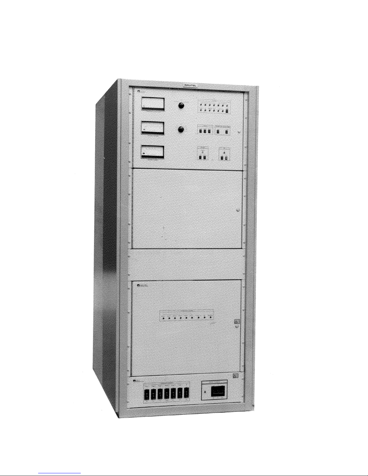
10 000 WATT FM BROADCAST TRANSMITTER
FM10
Figure 1-1 FM10 - 10 000 Watt FM Broadcast Transmitter
Page 1-5
15 July 1997
Page 26

10 000 WATT FM BROADCAST TRANSMITTER
FM10
Table 1-3 Special Tools
NOMENCLATURE PART, MODEL, OR TYPE NUMBER APPLICATION
(EQUIVALENTS MAY BE USED)
Tuning Tool HAS48* Adjust variable capacitors and
potentiometers.
Torque Wrench Capable of torquing to five inch-pounds
Installing power MOSFETS
(0.665 Newton-Meters)
* - Manufactured by, or available from, Nautel
Table 1-4 Glossary of Terms
TERM DESCRIPTION
Intermediate Power Amplifier (IPA) A module within the transmitter which amplifies the exciter's
RF output to a level sufficient to drive the final RF amplifiers.
PWB Printed Wiring Board (Printed Circuit Board)
PDM Pulse Duration Modulation (Pulse Width Modulation). Pulse-
time modulation in which the duration (width) of a pulse is
varied.
Page 1-6
15 July 1997
Page 27

10 000 WATT FM BROADCAST TRANSMITTER
FM10
SECTION 2
UNPACKING AND INSTALLATION
PLANNING AND SITE PREPARATION
2.1
Transmitter sites for Nautel's FM10 10 000 watt FM broadcast transmitters should be
prepared to receive the transmitter prior to its
delivery and/or installation. The following must be
taken into consideration when preparing new sites.
They should be used as the evaluating criteria at
existing sites. It is recommended that all
requirements be incorporated to ensure optimum
reliability and performance is obtained.
NOTE
Frequent reference is made to terminal boards on
the control/monitor PWB (A14). Refer to figure
MD-2 as an aid in locating the control/monitor
PWB. Refer to the control/monitor PWB's service
instruction manual for its assembly detail.
2.1.1 TRANSMITTER ROOM
REQUIREMENTS: The following transmitter
room requirements must be addressed when the
transmitter site is being finalized.
2.1.1.1 Transmitter Dimensions: Refer to figure
MD-15 for transmitter dimensions. These
dimensions identify floor space requirements and will
assist in determining cable lengths and routing.
2.1.1.2 Transmitter Clearances: A clearance of
at least four feet should be maintained at the front
and rear of the transmitter. Access to the transmitter
sides is not required for normal maintenance.
2.1.1.3.2 Fans in the power supply draw cooling air
through two large filters in the lower rear of the
transmitter, into the power supply compartment and
circulate it through the rectifier assemblies and power
supply modules. This air exhausts at the top front of
the compartment, up the cabinet sides to the opening
in the top of the transmitter.
2.1.1.3.3 A room air exchange rate of 1100 CFM
should achieve an acceptable intake/exhaust
temperature rise. If ducting is used, the static
pressure in the exhaust duct must be slightly
negative, while the static pressure at the rear of the
transmitter must be neutral or slightly positive.
2.1.1.4 Cooling: The transmitter room's ambient
air temperature must not exceed 50°C. For air
conditioning requirements, it can be assumed a
nominal 35 percent of the power being consumed,
from the AC power source, is converted to waste
heat.
NOTE
The worst case waste heat is from a transmitter with
a carrier frequency of 107.9MHz that is producing
11,000 watts of RF output power. The waste heat
from this configuration is a nominal 6300 watts.
Conversion to British thermal units (BTU's) is
accomplished by multiplying the waste heat wattage
by 3.413. In the example given the transmitter is
contributing 21,500 BTU's of waste heat to the
transmitter room.
2.1.1.3 Air Flushing: There are two air circulation
systems in the transmitter. One system circulates air
through the power supply compartment while the
other circulates air in the RF power module section.
The exhaust air of both systems is combined and
flushed out through an opening in the top of the
transmitter.
2.1.1.3.1 Fans in each RF power module draw
cooling air through two large filters in the upper rear
of the transmitter; circulate it through the modules
and exhaust it as a low velocity stream through
openings in the module front panels.
2.1.1.5 Heating: The transmitter room must
contain a heating system that will ensure its ambient
air temperature does not drop below 0°C.
2.1.1.6 Work Area: It is recommended that a
suitable work area with an adequate table surface be
provided adjacent to the transmitter to permit bench
adjustment/repair of modules.
Page 2-1
01 October 2002
Page 28

10 000 WATT FM BROADCAST TRANSMITTER
FM10
2.1.2 LIGHTNING PROTECTION:
Extremely high voltage/current transients are
produced when a lightning strike occurs. These
transients, which are probably the most significant
hazard to any solid state transmitter, may be passed
to the transmitter through the wiring connecting it to
its power source and its antenna system. It is
imperative that all practical precautions be taken to
protect the transmitter from this phenomenon. Refer
to the
Lightning Protection
section of Nautel’s
Recommendations for Transmitter Site Preparation
booklet for specific protection techniques. The
following requirements are considered to be essential.
2.1.2.1 Station Reference Ground: The site must
contain a station reference ground, as defined in the
Lightning Protection
section of Nautel’s
Recommendations for Transmitter Site Preparation
booklet. This ground must provide a continuous, low
impedance path to the earth. The transmitter
cabinet's designated reference ground point, the shield
of the coaxial feed cable and the ground connection
of the power source's surge protection devices must
be connected directly to the station reference ground.
2.1.2.2 AC Power Source: All conductors from
the AC power source should be protected by
bi-directional surge protection devices that are
connected between each conductor and the station
reference ground. A surge protector panel, that
contains suitably rated varistors is available from
Nautel for this purpose. If used, the surge protector
panel should be installed in close proximity to the
station reference ground.
NOTE
The AC power source usually presents the lowest
impedance path to ground potential and will
normally carry most of the lightning induced current
away from the transmitter site.
When lightning hits the power source, a significant
amount of induced current may flow towards the
transmitter. In this instance, the objective is to
route the current around the transmitter, instead of
through it, to the best ground available.
2.1.2.3 Antenna Feed Cable: The shield of the
antenna feed coaxial cable should be connected
directly to the station reference ground where it enters
the building. The centre conductor and the shield of
the feed cable should pass through a ferrite toroid
positioned between the shield ground at the building
entrance and the shield termination at the transmitter
reference ground. This toroid is transparent to the
RF signal, but will present impedance to transients
originating in the antenna.
2.1.2.4 Antenna Tower: The antenna tower is the
most likely target for lightning strikes. It is
imperative that it contain lightning protection devices
as the first line of defense against lightning strikes.
For towers which are grounded at their base, it is
recommended that a coaxial, gas-type spark gap be
installed where the coax enters the transmitter
building.
2.1.2.5 External Control/Monitor Wiring: All
external control/monitoring wiring, that may be
subjected to lightning induced transients, should be
interfaced to the station reference ground by surge
protection devices where they enter the building. In
addition, all conductors and their shields should pass
through a ferrite toroid which is positioned between
its surge protection device and the transmitter. This
toroid will be transparent to control/monitor signals,
but will present an impedance to lightning induced
transients.
2.1.3 ELECTRICAL POWER: The
transmitter is configured during manufacture to
operate from one of a variety of 50/60Hz three phase
ac power sources. The option selected is specified by
the purchaser. Refer to table 1-1 for an itemized
listing of standard voltage options. The AC power
source must meet all of the following requirements:
2.1.3.1 Nominal Voltage: The primary winding
of the main AC power transformer contains tap
options to accommodate voltages that differ from the
ideal voltage of the power source. There are five tap
options on the three-phase power transformers (5%
increments). The appropriate tap is selected during
installation to provide the optimum nominal voltage
for the transmitter.
2.1.3.2 Voltage Stability: The AC power source's
nominal voltage must be stable to within plus and
minus ten percent under all loading conditions. The
transmitter contains circuitry that maintains the RF
output at the preset carrier level for voltage
variations within this range.
Page 2-2
01 October 2002
Page 29

10 000 WATT FM BROADCAST TRANSMITTER
FM10
2.1.3.3 Power Consumption: When operating at
11 000 watts RF output, power consumption is a
nominal 17.9kVA. It is recommended the ac power
source have a 25% over capacity (minimum rating of
23kVA) to ensure adequate regulation.
2.1.3.4 External Switching: It is recommended
that all voltage carrying conductors from the AC
power source be controlled by an external switching
box that is located in close proximity to the
transmitter. This switch box should be clearly
marked TRANSMITTER EMERGENCY ON/OFF
SWITCH.
2.1.4 ANTENNA SYSTEM: The antenna
system must present an impedance of 50 ±j0 ohms at
the carrier frequency. Circuitry within the
transmitter will begin to reduce the forward power
when the reflected power level reaches 440 watts
(1.5:1 VSWR relative to 11 000 watts forward
power). This will prevent damage to the transmitter
from high VSWR loads.
2.1.6 SAFETY INTERLOCK: The external
safety interlock circuit is connected between TB1-11
and TB1-12 on the control/monitor PWB (A14). It
must present a short circuit (low impedance) between
the terminals when the interlock circuit is intact and it
is safe to enable the RF output. It must present an
open circuit when any interlock switch has been
activated and the RF output is required to be
inhibited. Any number of serial interlock switches
may be installed.
NOTE
The RF output will be restored, at an exponential
rate, over a 250 millisecond period, after the
integrity of the external interlock has been restored.
2.1.7 REMOTE CONTROL CIRCUITS:
See figure 2-1. The on/off status of the transmitter's
RF power stage, RF power level control, and the
protection reset functions can be controlled from a
remote location, using switching circuits that comply
with the following:
2.1.4.1 RF Feed Cable: The feed cable
interconnecting the transmitter and the antenna
system should be a suitably rated coaxial cable. The
transmitter's RF output is configured to accept a
non-gas type 3-1/8 inch EIA flange (male)
connection. The RF feed cable's transmitter end must
be terminated by the appropriate male inner
connector (bullet) which is not provided with the
transmitter.
2.1.5 RF DRIVE SOURCE: An exciter that
provides a frequency modulated RF drive in the 87.5
to 107.9MHz frequency band, at a nominal of 20
watts, into a 50-ohm load is required. A 19-inch
opening in the cabinet can be requested which will
accommodate Nautel's NE50 exciter. All other
exciters must be mounted externally. The exciter's
RF output cable (W39) is provided with the
transmitter. Any additional cabling required by an
external installation is not provided. The exciter
should contain an external on/off interlock or RF
mute capability. A set of form C contacts is provided
by the transmitter, at TB1 of the control/monitor
PWB (A14), as the exciter interlock/RF mute control.
If the exciter has an automatic level control (ALC)
circuit, it should be enabled, if possible.
NOTE
Remote control inputs have influence on transmitter
operation only when set to REMOTE. The external
control lines are interfaced with the transmitter
through opto-couplers located on the control/
monitor PWB (A14). A control input is activated
when +24V is present across its (+)/(-) inputs.
2.1.7.1 RF On Control: This remote control
circuit must be the equivalent of a single pole,
momentary contact switch. The switch must be in
the 'closed' position when pressed and return to the
'open' position when released. The switch must be
connected such that, when activated, +24V is
connected between the RF ON (+) (TB1-3) and RF ON
(-) (TB1-4) inputs. The operation of this remote
control will cause the transmitter to turn on.
2.1.7.2 RF Off Control: This remote control
circuit must be the equivalent of a single pole,
momentary contact switch. The switch must be in
the 'closed' position when pressed and return to the
'open' position when released. The switch must be
connected such that, when activated, +24V is
connected between the RF OFF (+) (TB1-1) and RF
OFF (-) (TB1-2) inputs. The operation of this remote
control will cause the transmitter to turn off.
Page 2-3
01 October 2002
Page 30

10 000 WATT FM BROADCAST TRANSMITTER
FM10
2.1.7.3 Protection Reset: This remote control
circuit must be the equivalent of a single pole,
momentary contact switch. The switch must be in
the 'closed' position when pressed and return to the
'open' position when released. The switch must be
connected such that, when activated, +24V is
connected between the PROTECTION RESET (+)
(TB1-5) and PROTECTION RESET (-) (TB1-6)
inputs. The operation of this remote control will
cause the RF power protection circuits to be reset,
allowing the RF output to be restored (if possible),
after a fault has caused the transmitter to be inhibited
indefinitely.
2.1.7.4 Power Increase: This remote circuit must
be the equivalent of a single pole, momentary contact
switch. The switch must be in the 'closed' position
when pressed and return to the 'open' position when
released. The switch must be connected such that,
when activated, +24V is connected between the
POWER INCREASE (+) (TB1-7) and POWER
INCREASE (-) (TB1-8) inputs. The operation of this
remote control will cause the RF output power to be
increased.
2.1.7.5 Power Decrease: This remote circuit must
be the equivalent of a single pole, momentary contact
switch. The switch must be in the 'closed' position
when pressed and return to the 'open' position when
released. The switch must be connected such that,
when activated, +24V is connected across the
POWER DECREASE (+) (TB1-9) and POWER
DECREASE (-) (TB1-10) inputs. The operation of
this remote control will cause the RF output power to
be decreased.
2.1.7.6 Low Power Select: This remote circuit
must be the equivalent of a single pole single throw
switch. The switch must be connected such that,
when activated, ground potential is applied to LOW
PWR SELECT (TB1-18) input. The operation of the
remote control will cause the RF output to be set to
the level adjusted for low power operation.
NOTE
A 24V supply is available at TB2-15 of the
control/monitor PWB (A14). The (+) terminal of
each control input may be connected to TB2-15,
which will allow activation of the input by
momentarily connecting the appropriate (-) terminal
to ground.
2.1.8 EXCITER INTERLOCK: Protection
circuitry within the transmitter will operate the
exciter interlock relay in an attempt to mute the
exciter's RF output when the exciter forward power is
excessive or when the transmitter is turned off. Refer
to exciter service manual and determine the required
contact arrangement, noting that:
- If a closed contact (normally open) is required
to mute the exciter's RF output, connect the
exciter interlock wires between TB1-13 (N/O)
and TB1-15 (COM) of the control/monitor
PWB (A14).
- If an open contact (normally closed) is required
to mute the exciter's RF output, connect the
exciter interlock wires between TB1-14 (N/C)
and TB1-15 (COM) of the control/monitor
PWB (A14).
2.1.9 RF PERFORMANCE MONITORING:
Forward power, reflected power and a sample of the
RF output are available for external monitoring.
2.1.9.1 Forward Power Level: A buffered DC
voltage that is representative of the forward power
level is available at the
FWD PWR SAMPLE
terminal (TB2-12) of the control/monitor PWB (14).
This voltage varies according to the square root of
the forward power level and will be 12.6 ± 0.6 volts
DC at 11 000 watts. A ground terminal is provided
at TB2-13 as a sample reference.
2.1.9.2 Reflected Power Level: A buffered DC
voltage that is representative of the reflected power
level is available at the REFLD PWR SAMPLE
terminal (TB2-14) of the control/monitor PWB
(A14). This voltage varies according to the square
root of the reflected power level and will be 7.1 ± 0.4
volts DC at 440 watts. A ground terminal is
provided at TB2-13 as a sample reference.
2.1.9.3 RF Output Sample: A -44 ± 2 dB sample
of the RF output (RF Monitor) is available at RF
MONITOR BNC coaxial connector J2. This output is
normally applied to a station modulation monitor, but
may be connected to an oscilloscope during
maintenance. The RF Monitor output will be a
nominal 4.7 volts RMS, into a 50 ohm load, when the
RF output power level is 11 000 watts.
Page 2-4
01 October 2002
Page 31

10 000 WATT FM BROADCAST TRANSMITTER
FM10
2.1.9.4 Exciter Power Sample: A DC voltage,
representative of the exciter forward power level, is
available at the EXCTR PWR SAMPLE terminal (TB2-
16) of the control/monitor PWB (A14). This voltage
varies according to the square root of the exciter
forward power level and will be 6.0 ±0.5 volts DC at
20 watts. The voltage source has an output
impedance of 100K ohms.
2.1.9.5 DC Input Current Level: A buffered DC
voltage that is representative of the TOTAL current
level is available at the TOTAL CUR SAMPLE terminal
(TB1-17) of the control/monitor PWB (A14). This
voltage varies linearly with the TOTAL current and
will be a nominal 2.00 volts DC at 200 amperes
current (10mV/amp).
2.1.9.6 DC Input Voltage Level: A buffered DC
voltage that is representative of the B+ volts level is
available at the B+ VOLTS SAMPLE terminal
(TB1-16) of the control/monitor PWB (A14). This
voltage varies linearly with the B+ VOLTS and will be
a nominal 0.5 volts DC at 70 volts (7.1mV/V). The
voltage source has an output impedance of 27.1K
ohms.
2.1.10 REMOTE ALARM INDICATIONS:
Outputs that indicate stress thresholds for critical
parameters have been exceeded are available on
terminals of the control/monitor PWB (A14). Each
output (except LOW BATTERY alarm) has a
Darlington transistor that provides an open collector
when inactive (no alarm) and a current-sink-toground when an alarm condition exists. Each
monitoring circuit must present impedance, between
the switching transistor and a positive DC voltage
source, that results in a current flow of 40
milliamperes or less. Each circuit's positive voltage
source must not exceed 28 V. Alarm outputs are
protected against transients and/or over voltage by a
33 volt zener diode.
NOTE
In most cases the RF output is inhibited when an
alarm condition is sensed. When the cause of the
alarm has been removed, the RF output will be
restored, at an exponential rate, over a 250
millisecond period. However, some protection
circuits will require activation of the PROTECT
RESET control before the RF output is restored.
2.1.10.1 IPA/RF Fail Alarm: The IPA/RF Fail
Alarm output is applied to the IPA/RF FAIL ALARM
terminal TB2-1 of the control/monitor PWB (A14).
During normal operation, the output is an open
collector. When the IPA module's RF drive input is
not satisfactory due to an exciter fault; or the RF
output of the IPA (intermediate RF) falls below 80%
of its normal level due to an IPA PA failure or an
IPA power supply fault; or the IPA output has an
excessive SWR due to faulty connections/ cabling;
IPA/RF FAIL ALARM
will switch to a current-sink-to-
ground. The RF output will be inhibited.
NOTE
Other alarm conditions which cause the RF output
of the transmitter to be inhibited will also activate
the IPA/RF FAIL ALARM.
2.1.10.2 PA/Module Fail Alarm: The
PA/Module Fail Alarm output is applied to the
PA/MOD FAIL ALARM
terminal TB2-2 of the
control/monitor PWB (A14). During normal
operation, the output is an open collector. When the
PA Volts current in any RF power module falls more
than 17% (nominally) below the average module
current, possibly due to a PA failure; or excessive
temperature is sensed within an RF power module
due to a fan failure or air blockage; or a low RF drive
level is detected at the input of an RF power module
due to faulty connections/cabling, the PA/MOD FAIL
ALARM output will switch to a current-sink-to-
ground. The RF output will be reduced.
2.1.10.3 High Reflected Power Alarm: The High
Refld Pwr Alarm output is applied to the HIGH
REFLD PWR ALARM terminal TB2-3 of the control/
monitor PWB. During normal operation, the output
is an open collector. When the reflected power
exceeds 100 watts (1.4:1 SWR relative to 11 000
watts of RF output), due to antenna icing or faulty
RF feed cabling, the HIGH REFLD PWR ALARM
output will switch to a current-sink-to-ground. When
the reflected power exceeds 440 watts, the RF output
forward power will be gradually reduced by the
transmitter's reflected power monitoring circuitry.
The RF output will be inhibited if the forward power
is reduced below 1500 watts or the peak reflected
power exceeds 1220 watts (2:1 SWR relative to
11 000 watts of RF output).
Page 2-5
01 October 2002
Page 32

10 000 WATT FM BROADCAST TRANSMITTER
FM10
2.1.10.4 AC Power Alarm: The AC Alarm output
is applied to the AC PWR ALARM terminal TB2-4 of
the control/monitor PWB (A14). During normal
operation, the output is an open collector. When the
AC power source voltage goes more than 15% above
or 15% below the ideal voltage for the power
transformer's selected primary winding taps, or one
of the three AC input phases is lost, the AC PWR
ALARM
output will switch to a current-sink-to-
ground. The RF output will be inhibited.
2.1.10.5 High Temperature Alarm: The High
Temp Alarm output is applied to the HIGH TEMP
ALARM
terminal TB2-5 of the control/monitor PWB
(A14). During normal operation, the output is an
open collector. When sensors detect excessive
temperature in an RF power module, IPA module or
power supply rectifier, the HIGH TEMP ALARM
output will switch to a current-sink-to-ground. The
following will cause a High Temp Alarm.
- Temperature of either three-phase rectifier
assembly exceeds 90°C. The transmitter's RF
output will be inhibited.
- Temperature in the IPA module exceeds 73°C.
The RF output will not be affected.
- Temperature in an RF power amplifier module
exceeds 85°C. The affected module will be
switched off, reducing the RF output.
2.1.10.6 PA Volts/Combiner Alarm: The PA
Volts/Combiner Alarm output is applied to the PA
VDC/CMBR ALARM terminal TB2-6 of the control/
monitor PWB (A14). During normal operation, the
output is an open collector. When the PA voltage
applied from the switching power supplies to the RF
power modules exceeds 55 VDC or the forward
power is too low for the level of PA voltage applied
to the RF power modules, the PA VDC/CMBR ALARM
output switches to a current-sink-to-ground. The RF
output is inhibited. Other alarm conditions which
cause a switching power supply to be inhibited, such
as excessive switching power supply temperature or
low PA volts, will activate the PA Volts/Combiner
alarm.
2.1.10.7 Interlock Open Alarm: The Interlock
Open Alarm output is applied to INTLK OPEN
ALARM
terminal TB2-7 of the control/monitor PWB
(A14). When the interlock circuit is intact (short
circuit) the output is an open collector. When the
interlock is open the
INTLK OPEN ALARM
output
switches to a current-sink-to-ground. The RF output
will be inhibited.
2.1.10.8 Fan Fail Alarm: The Fan Fail Alarm
output is applied to FAN FAIL ALARM terminal TB2-8
of the control/monitor PWB (A14). When the four
fans located in the power supply compartment and
the two fans on the lower, rear panel are functioning
normally, the output is an open collector. If one or
more of the fans should fail, the Fan Fail Alarm
output switches to a current-sink-to-ground. The RF
output will not be affected.
2.1.10.9 Low Battery Alarm: The Low Battery
Alarm output is applied to LOW BATTERY ALARM
terminal TB2-17 of the control/monitor PWB (A14).
When the backup battery voltage drops below 4.2V,
the Low Battery Alarm output switches to a current
sink-to-ground. The RF output is not affected. The
Low Battery Alarm output is an open collector when
the battery voltage is acceptable.
2.1.11 REMOTE STATUS INDICATIONS:
External monitoring outputs that indicate the status
of operator controlled circuits are available at
terminals of TB2 on the control/monitor PWB (A14).
All status outputs, except REMOTE STATUS, employ
a Darlington transistor. Each output provides an
open collector when inactive and a current-sink-toground when active. Each external monitoring circuit
must present an impedance, between the transistor
and a positive DC voltage source, that will result in a
current flow of 40mA or less. The voltage source
must not exceed 28V. Each output is protected
against transients and/or over voltage by a 33 volt
zener diode.
2.1.11.1 Remote Status: The Remote Status
output is applied to REMOTE STATUS terminal
TB2-11 of the control/monitor PWB (A14). When
the control/monitor panel's CONTROL switch is set to
LOCAL, this output is an open circuit (open relay
contacts) and the remote control functions have no
influence on the transmitter's on/off status or the
protection/alarm reset functions. When the
CONTROL switch is set to REMOTE
STATUS output is a connected to ground. The
,
the REMOTE
transmitter's on/off status and the protection/alarm
reset functions can be controlled remotely.
Page 2-6
01 October 2002
Page 33

10 000 WATT FM BROADCAST TRANSMITTER
FM10
2.1.11.2 RF On Status: The RF On Status output
is applied to RF ON STATUS terminal TB2-9 of the
control/monitor PWB (A14). When the external
interlock is open or a local or remote RF OFF has
been initiated, this output is an open collector. When
the interlock circuit is intact and a local or remote RF
ON has been initiated, the
RF ON STATUS
output is a
current-sink-to-ground.
2.1.11.3 Transmitter Ready Status: The XMTR
Ready Status output is applied to XMTR READY
terminal TB2-10 of the control/monitor PWB (A14).
When the AC/DC power supply is not producing a
regulated +5V (no unregulated 24 V) and the control
functions are not operable, this output is open
collector. When the AC/DC power supply is
producing a regulated +5V, and control functions are
operable (locally or remotely as appropriate), the
XMTR READY output is a current sink to ground.
2.1.12 PARTS SUPPLIED BY NAUTEL: The
following parts/materials are supplied by or are
available from Nautel.
2.1.12.1 Parts Removed During Disassembly For
Shipment: All the parts that were removed during
disassembly for shipment and are required to
reassemble the transmitter are provided. An itemized
listing of the parts is not provided in this manual, as
the extent of disassembly is determined by the method
of shipment. Detailed packing lists will be included
with each transmitter shipment.
2.1.13 PARTS REQUIRED BUT NOT
SUPPLIED BY NAUTEL: Some parts and
materials required to complete an installation are not
supplied with the transmitter or are not provided by
Nautel. The user must supply these parts. Each
installation will dictate the parts required, and will
normally include the following:
- A suitable 50-ohm RF output coaxial cable,
terminated by a 3 1/8 inch EIA connector, with
inner conductor, at the transmitter end.
- All external control/monitor wiring, including
their associated terminating devices and
conduit/conduit clamps.
- All electrical power cables, including conduit,
terminating devices and conduit clamps.
2.1.13.1 Surge Protector Panel: A surge protector
panel, that is rated for the AC power source to be
applied to the transmitter, is available from Nautel.
The surge protector panel will help protect the
transmitter against lightning induced voltage
transients on the AC power source.
2.1.14 TEST EQUIPMENT AND SPECIAL
TOOLS: The test equipment required to install and
maintain the transmitter is listed in table 1-2 and the
special tools are listed in table 1-3.
2.1.12.2 Ancillary Parts: An ancillary parts kit is
provided with each transmitter. These parts are
provided to ensure initial installation is not delayed
because of a lost or damaged part and to allow the
user to maintain the equipment until a comprehensive
maintenance spares kit is obtained. They are not
intended to be long term maintenance spares.
Detailed information about these parts is not included
in this manual. The ancillary parts kit contents is
itemized in its packing list.
Page 2-7
01 October 2002
Page 34

10 000 WATT FM BROADCAST TRANSMITTER
FM10
NON-TECHNICAL PRE-COMMISSIONING
2.2
On delivery of the transmitter, the
following non-technical procedures should be
observed and completed.
NOTE
Non-technical procedures are defined as being those
procedures that do not require technical knowledge
of transmitter circuits or their operation to
complete.
2.2.1 ACCEPTANCE OF SHIPMENT: All
shipments should be inspected for transit damage
prior to acceptance.
Sufficient manpower or mechanical assistance
should be on hand when removing the transmitter
cabinet from its packing crate. The crate may
weigh in excess of 250 kilograms (550 pounds)
2.2.2 UNPACKING INSTRUCTIONS: The
unpacking instructions are dictated by method of
packaging for shipment. Transmitters not shipped by
electronic equipment moving specialists may be
packed in wooden crates, with the number of crates
determined by the extent of disassembly for shipment.
Instructions accompany any crate that requires
special unpacking information. Packing lists provide
detailed listings of shipment contents.
NOTE
The transmitter will be partially disassembled for
shipment. As a minimum, the intermediate power
amplifier (IPA) module, the RF power modules and
the power transformer assembly will be removed.
The extent of any additional disassembly will be
dictated by the shipping method, site information
provided by the user and the handling equipment of
the mover.
2.2.3 ASSEMBLY/INSTALLATION: The
following paragraphs provide step-by-step assembly
instructions for the FM10 transmitter, which is
partially disassembled for shipment.
NOTE
Partially disassembled transmitters should be
placed in their final location prior to completing
assembly.
2.2.4 INSTALLATION OF EXTERNAL
CONTROL/MONITOR WIRING: Connect
wiring originating from the remote control/monitoring
devices to terminating points on control/monitor
PWB A14, as follows:
NOTE
Remote control and remote monitor wiring
terminate on the control/monitor PWB (A14). Refer
to figure MD-2 as an aid to locating the control/
monitor PWB and to its service instruction manual
as an aid in locating terminal blocks TB1/TB2. The
terminal blocks will accept wire sizes #14 through
#24.
The user must punch out an appropriate sized cable
entry hole where the control/monitor cables enter
the cabinet. The preferred entry point is the top lefthand side of the cabinet. Refer to figure MD-15 to
determine the recommended cable entry location.
(a) Punch or verify a cable entry hole for the
control/monitor wiring has been punched in the
cabinet at the desired cable entry point.
(b) Obtain four 38mm ferrite toroids (LXP38)
from the ancillary parts kit.
(c) Route control and monitor wires; through cable
entry hole determined in step (a), to the vicinity
of the control/monitor PWB (A14).
(d) Pass all control/monitor wires, including their
shields, through two ferrite toroids. The wiring
to TB1 should pass through one pair of toroids
and the wire to TB2 should pass through the
other pair. If practical, the wires should pass
through a minimum of two times (two turns).
(e) Using figure 2-1 as a guide, determine the
specific destination of each wire.
(f) Cut each wire to the required length and remove
approximately 3/8" of insulation from the end
of each conductor.
(g) Insert the control/monitor wiring into the
terminals of the control/monitor PWB (A14)'s
TB1 and TB2, as identified in figure 2-1.
Ensure their securing screws are firmly
tightened.
Page 2-8
01 October 2002
Page 35

10 000 WATT FM BROADCAST TRANSMITTER
FM10
NOTE
DC return for remote alarm/status monitoring
circuit's DC power source should be obtained from
TB2-18.DC return for the forward/reflected power
monitoring circuits should be obtained from TB2-
13. Refer to paragraph 2.1.8 to install exciter
interlock wiring.
2.2.5. INSTALLATION OF AC
POWER SUPPLY ASSEMBLY: Install the AC
power supply (A1) in the cabinet's power supply
compartment, noting it consists of the power
transformer and two B+ Volts chokes, as follows:
(a) Disconnect the lower, rear panel from the back
of the cabinet, noting there is a 2 AWG black
wire connected to it and swing it off to one side.
Ensure painted surfaces are protected and the
wiring is not damaged.
NOTE
It may be necessary to disconnect the four 22 AWG
wires (#99, 100, 101 and 102) from TB2 when
removing the lower, rear panel.
(b) Open the power supply control panel and
secure it in a manner that will prevent it from
obstructing access to the interior of the cabinet.
(f) Locate two black 2 AWG wires (#314 and 318)
that will be attached to B+ volts choke A1L1, noting
they are tyrapped together at the right-hand side of
the power supply compartment when viewed from
rear. Remove shipping tyraps.
(g) Locate two black 2 AWG wires (#315 and 319)
that will be attached to B+ volts choke A1L2,
noting they are tyrapped together at the lefthand side of the power supply compartment,
when viewed from rear. Remove shipping
tyraps.
(h) Locate six black 6 AWG wires (#308, 309,
310, 311, 312 and 313) that will be attached to
the power transformer (A1T1), noting they are
tyrapped together in the back of the power
supply compartment, when viewed from rear.
Remove shipping tyraps.
(i) Locate connector P15 that will be attached to
J1 of the power supply, noting it has been
secured to the wiring harness at the right-hand
side of the power supply compartment, when
viewed from the rear. Remove shipping tyraps.
(c) Remove the power supply air blocker, noting it
prevents frontal access to the rear power supply
compartment. Remove the two screws securing
it to the IPA power supply cover at the bottom
and the two screws securing it to the horizontal
air blocker at the top. Then, carefully remove
the air blocker. Retain all hardware.
(d) Locate an unidentified black 2 AWG jumper
wire that will be attached to the power
transformer's ground stud, noting it is located
adjacent to the safety ground stud at the rear of
the cabinet.
(e) Locate three black 2 AWG wires (#305, 306
and 307) that will be attached to the power
transformer (A1T1), noting they are tyrapped
together at the left-hand side of the power
supply compartment, when viewed from rear.
Remove shipping tyraps.
The power supply weighs approximately 200
kilograms (441 pounds). Sufficient manpower or
mechanical assistance should be available, to
prevent injury to personnel or damage to the
equipment.
(j) Position the power supply at the rear of the
transmitter with its power transformer's
primary terminals (H1, H2 and H3) facing
away from the cabinet.
(k) Remove the bolts securing the power supply to
its shipping pallet.
(l) Note the four 3/8-16 x 1 bolts, flat washers and
split washers that are threaded into the
transformer mounting holes in the cabinet
bottom. Remove these bolts and retain.
Page 2-9
01 October 2002
Page 36

10 000 WATT FM BROADCAST TRANSMITTER
FM10
NOTE
It is recommended a six-foot long 2 x 4 board be
used, in conjunction with the lifting bracket mounted
on top of the power supply, as an aid in lifting the
power supply into the transmitter.
(m) Temporarily remove P33 from J1 of power
supply module A9 in the front of the
transmitter, noting it prevents access to the
power supply's lifting bracket when connected.
(n) Using extreme care to avoid damage to wiring
and/or assemblies, place the power supply in
the transmitter and align its base with the
mounting holes on the bottom of the cabinet
(the transformer's primary terminals should be
facing the rear).
NOTE
Since the wires located in step (h) are difficult to
access, it may be necessary to connect them to the
appropriate terminals of the power transformer (see
table 2-1) before aligning the power transformer
with the cabinet's mounting holes.
(o) Secure the power transformer to the cabinet
using the four 3/8-16 x 1 bolts and associated
flat and split washers removed in step (l).
(p) Connect the wiring located in steps (d) thru (h)
to the appropriate terminals of the power
transformer (A1T1) as identified in table 2-1.
(q) Plug connector P15, located in step (i), into J1
of the power supply.
(r) Plug connector P33, removed in step (m), into
J1 of switching power supply A9 in the front of
the transmitter.
(s) Replace the power supply air blocker using the
hardware retained in step (c).
Table 2-1 Power Transformer Wire Connections
A1 WIRE WIRE WIRE SOURCE
TERM # SIZE COLOUR
T1-H1 305 2 BLK A4CB1A-LOAD
T1-H2 306 2 BLK A4CB1B-LOAD
T1-H3 307 2 BLK A4CB1C-LOAD
T1-X1 308 6 BLK A2A1U1-AC
T1-X2 309 6 BLK A2A1U2-AC
T1-X3 310 6 BLK A2A1U3-AC
T1-Y1 311 6 BLK A3A1U1-AC
T1-Y2 312 6 BLK A3A1U2-AC
T1-Y3 313 6 BLK A3A1U3-AC
L1-2 314 2 BLK A2A1 (+)
L2-1 315 2 BLK A3A1 (+)
L1-1 318 2 BLK A4E1
L2-2 319 2 BLK A4E2
T1-Gnd -2 BLK Ground
(t) Do not install the lower, rear panel at this time.
Access to the TB1 in the power supply
compartment is required when installing the ac
power source wiring as detailed in paragraph
2.2.6.
NOTE
The lower, rear panel, when it is installed, prevents
unintentional access to the power supply
compartment, which contains exposed ac voltages.
If the correct primary winding tap connections for
the power transformer have not been chosen in step
(p), the panel will also have to be removed during
the technical pre-commissioning procedures
described in the transmitter's technical manual.
2.2.6 INSTALLATION OF AC POWER
SOURCE WIRING: Connect the wiring from the
AC power source to the appropriate terminals of
terminal block TB1, noting it is located at the lower,
rear, left-hand side of the cabinet.
Do not operate the transmitter with the power
supply air blocker removed.
(a) Verify a suitable cable entry hole (punched in
the top or existing in the bottom) is available
for the ac power source wiring at the desired
cable entry point.
Page 2-10
01 October 2002
Page 37

10 000 WATT FM BROADCAST TRANSMITTER
FM10
Table 2-2 Three-Phase AC Power Connection
TB1-1 LINE
TB1-2 LINE
TB1-3 LINE
TB1-5 GROUND
NOTE
If top-entry is desired, the user must punch an
appropriate sized cable entry hole in the top of the
cabinet. Figure MD-15 identifies the preferred topentry location. It is recommended the wiring be
installed in a metal conduit and the conduit be
rigidly attached to the cabinet at the entry hole.
If bottom-entry is desired (when the wiring is in a
floor mounted trench or the transmitter is sitting on
a pedestal), two knock-outs which are located at the
rear of the cabinet, are available for cable entry.
(b) Obtain two 72mm ferrite toroids (LY30) from
the ancillary parts kit.
2.2.7 IPA/RF POWER MODULE
INSTALLATION: Install the IPA and RF power
modules as follows:
(a) Remove the upper, rear panel, noting there is a
safety ground wire connected to it.
Temporarily remove this wire to allow panel
removal.
(b) Locate and remove a plastic bag containing the
RF power/IPA module retaining hardware,
noting it should be fastened to a cable anchored
to the rear of an RF power module's support
tray.
(c) Locate the wiring (three coaxial cables, a cable
terminated by a 5-contact connector and a cable
terminated by a 1-contact connector) that will
be connected to the IPA module, noting the
three coaxial cables (W37, W38 and W40) are
located in the ancillary kit and the 5-contact
and 1-contact connectors are secured to the rear
of the IPA module's support tray.
(c) Route the AC power source wires through the
selected cable entry hole to the vicinity of the
AC power terminal block (TB1). Refer to
figure MD-2 to determine its location.
(d) Pass all AC power source wires, including the
ground wire, through the ferrite toroids
obtained in step (b). If practical, wires should
pass through a minimum of two times (two
turns).
(e) Using table 2-2 as a guide, determine the
destination of each wire.
(f) Cut each wire to the required length and remove
approximately 1.9cm (0.75 inches) of
insulation from the end of each conductor.
(g) Connect the wiring to the terminals of TB1 as
tabulated in table 2-2. Ensure securing screws
are firmly tightened.
NOTE
Selection of the power transformer's primary
winding taps is completed during the technical precommissioning procedures (paragraph 2.3).
(d) Locate the wiring (seven coaxial cables, a
cable terminated by a 5-contact connector, and
a cable terminated by a 3-contact connector)
that will be connected to each RF power
module, noting the seven coaxial cables are
located in the ancillary kit and the 5-contact
and 3-contact connectors are secured to the rear
of the associated RF power module's support
tray.
(e) Locate the 36 coaxial connectors that will be
connected to the RF combiner/final filter,
noting they are part of the coaxial cables
located in step (d).
(f) Locate the 8 coaxial connectors that will be
connected to the intermediate RF drive splitter,
noting they are part of the coaxial cables
located in steps (c) and (d).
(g) Open the control/monitor panel and secure it in
a manner that will prevent it from obstructing
access to the RF power module support trays.
(h) Open blank panel immediately beneath the
control/monitor panel and secure it in a manner
that will prevent it from obstructing access to
IPA/RF power module support trays.
Page 2-11
01 October 2002
Page 38

10 000 WATT FM BROADCAST TRANSMITTER
FM10
(i) Install the six RF power modules (A18 thru
A23) in the appropriate support trays (see
figure MD-1). Ensure retaining studs of each
module pass thru the holes in the rear of its
support tray.
(j) Install the IPA module (A17) in its support tray
(see figure MD-1). Ensure its retaining studs pass thru the holes in the rear of its support
tray.
NOTE
Flat washers and combination hex nut/star washers
required to secure the modules to their support tray
are in the plastic bag located in step (b).
(k) Secure the IPA and RF power modules to their
support trays by installing and firmly tightening
a #10 flat washer and combination 10-32 hex
nut/star washer to the retaining stud protruding
through each support tray.
Table 2-3 Module Connector Mating Information
RF POWER CABLE DESTINATION
MODULE
IPA A17J1 W37P1 W37P2 A15J7
IPA A17J2 W38P1 W38P2 A15J8
IPA A17J3 P41 - IPA A17J4 P4 - IPA A17J5 W40P2 W40P1 A16J2
A A18J1 W1P1 W1P2 A24J1
A A18J2 W2P1 W2P2 A24J2
A A18J3 W3P1 W3P2 A24J3
A A18J4 W4P1 W4P2 A24J4
A A18J5 W5P1 W5P2 A24J5
A A18J6 W6P1 W6P2 A24J6
A A18J7 P35 - A A18J8 P5 - A A18J9 W41P2 W41P1 A15J1
B A19J1 W7P1 W7P2 A24J7
B A19J2 W8P1 W8P2 A24J8
B A19J3 W9P1 W9P2 A24J9
B A19J4 W10P1 W10P2 A24J10
B A19J5 W11P1 W11P2 A24J11
B A19J6 W12P1 W12P2 A24J12
B A19J7 P36 - B A19J8 P6 - B A19J9 W42P2 W42P1 A15J2
RF power module retaining hardware provides the
DC return path for the PA VDC power source.
Ensure the retaining hardware is firmly tightened.
(l) Complete the electrical interconnection of the
IPA and RF power modules by mating the
connectors that terminate the coaxial cables and
wiring that were located in steps (c) and (d) as
tabulated in table 2-3.
NOTE
Remove all plastic cap-plugs from BNC connectors.
(m) Complete the electrical interconnection of the
RF combiner/final filter by mating the
connectors that terminate coaxial cables located
in step (e) as tabulated in table 2-3.
(n) Complete the electrical interconnection of the
intermediate RF drive splitter by mating the
connectors that terminate coaxial cables located
in step (f) as tabulated in table 2-3.
(o) Do not install the upper, rear panel at this time.
Access to the rear of the IPA module is
required to connect the RF drive from the
exciter. If the exciter is located in the cabinet,
access is also required to complete its
installation.
C A20J1 W13P1 W13P2 A24J13
C A20J2 W14P1 W14P2 A24J14
C A20J3 W15P1 W15P2 A24J15
C A20J4 W16P1 W16P2 A24J16
C A20J5 W17P1 W17P2 A24J17
C A20J6 W18P1 W18P2 A24J18
C A20J7 P37 - C A20J8 P7 - C A20J9 W43P2 W43P1 A15J3
D A21J1 W19P1 W19P2 A24J19
D A21J2 W20P1 W20P2 A24J20
D A21J3 W21P1 W21P2 A24J21
D A21J4 W22P1 W22P2 A24J22
D A21J5 W23P1 W23P2 A24J23
D A21J6 W24P1 W24P2 A24J24
D A21J7 P38 - D A21J8 P8 - D A21J9 W44P2 W44P1 A15J4
E A22J1 W25P1 W25P2 A24J25
E A22J2 W26P1 W26P2 A24J26
E A22J3 W27P1 W27P2 A24J27
E A22J4 W28P1 W28P2 A24J28
E A22J5 W29P1 W29P2 A24J29
E A22J6 W30P1 W30P2 A24J30
E A22J7 P39 - E A22J8 P9 - E A22J9 W45P2 W45P1 A15J5
F A23J1 W31P1 W31P2 A24J31
F A23J2 W32P1 W32P2 A24J32
F A23J3 W33P1 W33P2 A24J33
F A23J4 W34P1 W34P2 A24J34
F A23J5 W35P1 W35P2 A24J35
F A23J6 W36P1 W36P2 A24J36
F A23J7 P40 - F A23J8 P10 - F A23J9 W46P2 W46P1 A15J6
Page 2-12
01 October 2002
Page 39

10 000 WATT FM BROADCAST TRANSMITTER
FM10
2.2.8 EXCITER INSTALLATION: Install the
exciter (internally or externally) and connect its
interconnecting electrical wiring as follows:
(a) Verify the exciter has been subjected to a
functional test, it has been set to generate the
desired carrier frequency (ƒc), and it is fully
operational.
2.2.8.1 Internally Mounted Nautel Exciter:
When the transmitter has been configured to
accommodate the internal installation of a Nautel FM
digital exciter, install it as follows:
NOTE
An exciter mounting kit must be installed in the
space identified as being reserved for internal
exciter mounting in figure MD-1. Unless otherwise
specified in contract documents, this kit will be
installed when a Nautel exciter is to be utilized as
the RF drive source.
The blank panel depicted in figure MD-1
(immediately under the hinged access panel) will not
be installed when an exciter mounting kit is
installed.
(c) Plug the exciter's AC power cord into the
EXCITER AC ONLY receptacle, noting it is
located on the rear panel immediately below the
'E' RF power module.
(d) Obtain the six foot RF coaxial cable that is
terminated by BNC connectors labelled
W39P1/W39P2 from the ancillary parts kit and
install it between the RF output connector of
the exciter and the EXCITER I/P connector (J1)
of the IPA input power probe. The IPA input
power probe is mounted on the interior side
panel which is immediately behind the IPA
module (see figure MD-2).
(e) Locate shielded wire #400, which is tied back
near the rear of the exciter and connect it
between TB1-4 (conductor) and TB1-5 (shield)
of the exciter's interface appropriate exciter
input PWB (A10).
(f) Connect the program input to the appropriate
exciter input, as detailed in the exciter's
technical instruction manual.
(g) Reinstall the transmitter’s upper, rear panel,
ensuring the safety ground wire is reconnected.
The AC voltage applied to the
EXCITER AC ONLY
receptacle (J1) is dependent on the RMS voltage of
the transmitter's 3ø AC power source. It will be
115 VAC RMS when the phase-to-phase voltage of
the power source is 208 VAC or it will be 230 VAC
RMS when the phase-to-phase voltage is 380/415
VAC. Prior to plugging the exciter's AC power
cord into the
EXCITER AC ONLY
receptacle, verify
the exciter is configured to operate from the
available voltage. Failure to observe this
precaution may result in damage to the exciter
.
(a) Verify the exciter's AC input voltage selection
card is oriented to select the AC voltage
available at the EXCITER AC ONLY receptacle.
NOTE
Nautel exciters have provision to operate from 115
VAC or 230 VAC by changing the orientation of a
voltage selection card in their line filters.
(b) Install the exciter in the exciter mounting
drawer slides, noting it is installed from the
front of the cabinet.
2.2.8.2 Externally Mounted Exciter: When the
exciter is located outside of the transmitter, make the
electrical interconnections as follows:
NOTE
Connections between the exciter and the transmitter
should enter the transmitter thru the same cable
entry hole as the remote control lines.
(a) Obtain the 15 foot RF coaxial cable that is
terminated by BNC connectors labelled
W39P1/W39P2 from the ancillary parts kit and
install it between the RF output connector of
the exciter and the EXCITER I/P connector (J1)
of the IPA input power probe. The IPA input
power probe is mounted on the interior side
panel which is immediately behind the IPA
module (see figure MD-2).
(b) When applicable, interconnect the exciter's RF
mute (safety interlock) control and the
transmitter's exciter interlock control, using a
single conductor shielded wire. The exciter
interlock control is available on the EXCITER
INTERLOCK terminals of TB1 on the
transmitter's control/monitor PWB (A14).
Page 2-13
01 October 2002
Page 40

10 000 WATT FM BROADCAST TRANSMITTER
FM10
NOTE
A set of relay contacts are connected to TB1-15
(COM), TB1-13 (N/O) and TB1-14 (N/C) as the
exciter interlock control. The relay status
identification on TB1-13 and TB1-14 does not
reflect the energized/de-energized state of the relay,
it represents the relay state when the exciter's RF
output is not to be muted.
- When an open circuit is required for normal
operation and a contact closure is required to
mute the exciter's RF output, connect the
exciter interlock conductor to TB1-13 (N/O)
and its shield to TB1-15 (COM).
-
When an contact closure is required for normal
operation and an open circuit is required to
mute the exciter's RF output, connect the
exciter interlock conductor to TB1-14 (N/C)
and its shield to TB1-15 (COM).
(c) Reinstall the transmitter’s upper, rear panel,
ensuring the safety ground wire is reconnected.
2.2.9 RF OUTPUT ACCESS: Remove the
protective cover from the EIA flange connection on
the top of the cabinet (RF output) and the dowel from
its inner connector as follows:
(a) Remove the four 1/4-20 hex nuts securing the
EIA flange connection's aluminum shipping
cover. Retain hardware.
(b) Carefully withdraw aluminum shipping cover,
noting it contains a dowel that is inserted in the
EIA inner connector. Discard shipping cover.
(c) Obtain output plate assembly (P/N 182-6031)
included in the shipment.
(d) Using the hardware retained from step (a),
install the output plate assembly on the top of
the RF output, noting that the studs of the
assembly are to point upwards (refer to figure
MD-11). Tighten hardware securely.
2.2.10 INSTALLATION OF RF FEED
CABLE: Connect an RF feed coaxial cable, that has
been cut to the required length, to the transmitter's
RF output; noting the RF feed cable termination point
is located at the top of the RF output filter (refer to
figure MD-15 for location and dimensional
information).
NOTE
The transmitter's RF output should be applied to a
dummy load during the commissioning procedure's
initial turn-on. If the RF feed cable is not connected
to a switching circuit that permits antenna/dummy
load selection, ensure the RF feed cable for the
dummy load is connected to the transmitter's RF
output connection until otherwise specified during
the commissioning procedures.
2.2.10.1 Connection of RF Feed Cable: Connect
the RF feed cable to the transmitter's RF output
(3 1/8 EIA inch flange) connection as follows:
(a) Verify the RF feed cable is in place and has
been cut to the required length.
(b) Install a 3 1/8-inch EIA flange connector on the
feed cable.
NOTE
If the RF feed cable's EIA flange connector does not
have a male connector for the centre conductor, an
EIA bullet for a 3 1/8 inch EIA flange connector
must be obtained.
(c) Locate and remove four 3/8 nuts and three 3/8-
inch washers from the EIA flange connector
mounting studs on the top of the RF power
probe.
(d) Carefully install the RF feed cable's 3 1/8 inch
EIA flange connector on the RF power probe's
flange mounting studs. Ensure its bullet mates
with the rigidly mounted cup connector on the
RF power probe. Secure using attaching
hardware removed in step (c). Ensure nuts are
firmly tightened.
2.2.11 REFERENCE GROUND INTERCONNECTION: Connect a continuous, low-
impedance conductor (0 AWG copper wire, two-inch
copper strap or equivalent), as described in Nautel's
'Lightning Protection for Radio Transmitter Stations'
booklet, between the station reference ground and the
insulated reference ground stud at the bottom rear of
the cabinet.
Page 2-14
01 October 2002
Page 41
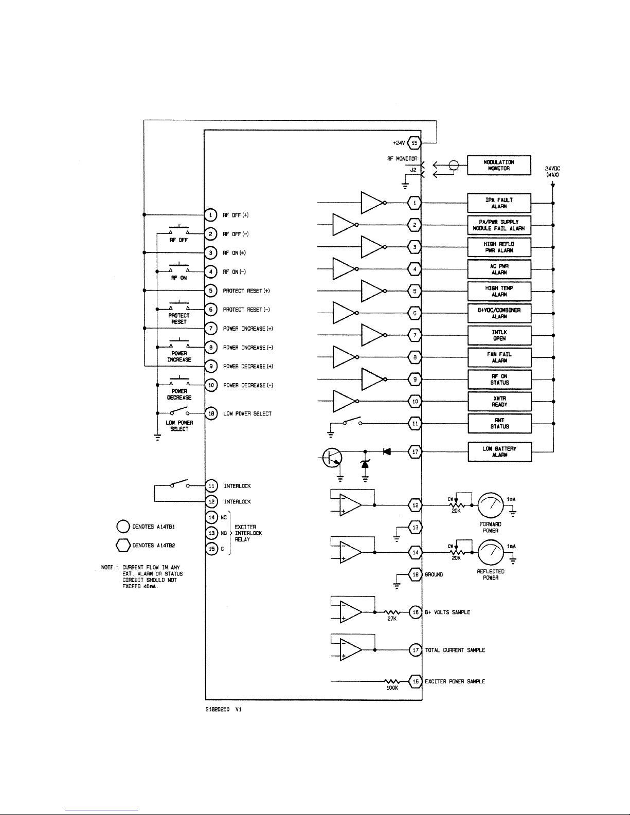
10 000 WATT FM BROADCAST TRANSMITTER
FM10
Figure 2-1 External Input/Output Interface
Page 2-15
01 October 2002
Page 42

10 000 WATT FM BROADCAST TRANSMITTER
FM10
TECHNICAL PRE-COMMISSIONING
2.3
Prior to applying AC power and turning on
the transmitter, some circuits must be customized to
the station's power source and operating
requirements. The following should be completed.
NOTE
Technical pre-commissioning procedures require
technical decisions and customization of electrical
circuits. They should be incorporated by the station
engineer or a competent electronic technician.
2.3.1 SELECTING PWR TRANSFORMER'S
PRIMARY WINDING TAPS: Connect the wires
from the three-phase transformer's H1, H2 and H3
terminals to the appropriate primary winding taps as
follows:
WARNING
Ensure AC power source is switched off at the
service entrance. If this precaution is not
observed, voltages that may cause serious injury or
death will be present on circuit breaker and
transformer terminals.
(a) Determine fully loaded, mean, RMS, line-to-
line voltage of the AC power source and record
this voltage for future reference.
(b) Verify the power transformer is rated for the
voltage determined in step (a) by noting voltage
rating on its nameplate.
(c) Enter the appropriate nominal ac voltage
column of table 2-4 with the mean, RMS, lineto-line voltage obtained in step (a) and
determine which primary winding taps should
be used.
(f) Re-install the lower panel on the rear of the
cabinet, using the attaching hardware removed
in step (d).
2.3.2 SELECTING EXCITER INTERLOCK
CONNECTIONS: Refer to exciter service manual
and determine the required contact arrangement to
mute the exciter's RF output, noting that:
- If an open circuit is required for normal
operation and a contact closure is required to
mute the exciter's RF output, connect the
exciter interlock wires between TB1-13(N/O)
and TB1-15(COM) of the transmitter's control/
monitor PWB (A14).
- If a contact closure is required for normal
operation and an open circuit is required to
mute the exciter's RF output, connect the
exciter interlock wires between TB1-14(N/C)
and TB1-15(COM) of the transmitter's control/
monitor PWB (A14).
2.3.3 LOAD RESISTANCE CHECK FOR
B+ VOLTAGE POWER SUPPLY: Check for
short circuits on the load of the B+ voltage power
supply as follows:
(a) Verify all PWR MDL circuit breakers are set to
OFF.
(b) Measure load resistance for the B+ volts power
supply by connecting an ohmmeter between L12 of power supply assembly and ground.
Repeat for L2-2. Refer to figure MD-2 and
MD-3 to locate A1L1 and A1L2.
(c) Resistance reading obtained in step (b) should
indicate an impedance of 10K ohms or greater.
(d) Gain access to the transformer's primary
winding taps by removing the screws securing
the lower rear panel to the cabinet. Carefully
set the panel to one side.
(e) Connect the moveable wire from each of the
power transformer's input terminals (H1, H2
and H3) to the tap of its associated primary
winding identified in step (c) noting the tap for
all three primary windings must be the same
(A, B, C, D or E).
NOTE
There are large storage capacitors in the main B+
Volts power supply. Resistance readings will not be
accurate until they are fully charged to the voltage
being applied by the ohmmeter.
2.3.4 CONTROL/MONITOR BATTERY:
The control/monitor PWB's backup batteries should
not be installed until AC power is applied to the
transmitter. Refer to section 4 of this manual for
control/monitor battery installation procedure.
Page 2-16
01 October 2002
Page 43

10 000 WATT FM BROADCAST TRANSMITTER
FM10
Table 2-4 Primary Winding Tap Selection for Three-Phase Power Transformer A1T1
NOMINAL AC VOLTAGE PRIMARY WINDING TAPS
(RMS - PHASE-TO-PHASE)
208 VOLTS 380/415 VOLTS H1 H2 H3
193 - 203 351 - 369 ø1-A ø2-A ø3-A
204 - 213 370 - 389 ø1-B ø2-B ø3-B
214 - 223 390 - 410 ø1-C ø2-C ø3-C
224 - 235 411 - 425 ø1-D ø2-D ø3-D
236 - 248 426 - 448 ø1-E ø2-E ø3-E
NOTE
Refer to section 4 for pre-startup and
commissioning of this equipment.
Page 2-17
01 October 2002
Page 44

10 000 WATT FM BROADCAST TRANSMITTER
FM10
SECTION 3
CONTROLS AND INDICATORS
GENERAL
3.1
The following section is intended to
familiarize operators and maintainers with the
various controls and indicators contained in the
transmitter.
AC/DC POWER SUPPLY CONTROLS AND
INDICATORS
3.2
Table 3-1 lists the AC/DC power supply
related controls and indicators. Refer to figures MD1 and MD-2 to locate the power supply, noting it
comprises the following assemblies: AC power
supply (A1), two 3-phase rectifiers (A2 and A3),
circuit breaker panel (A4), power supply control
panel (A5), six PA switching power supplies (A6,
A7, A8, A9, A10 and A11), IPA switching power
supply (A12), low voltage power supply (A26) and
two fan assemblies (A27 and A28).
Refer to figure MD-3 for the AC power supply's
assembly detail.
Refer to figure MD-4 for the 3-phase rectifier's
assembly detail.
Refer to figure MD-5 for the circuit breaker panel's
assembly detail.
Refer to figure MD-6 for the power supply control
panel's assembly detail.
Refer to the switching power supply's service
instruction manual for it's assembly detail.
Refer to figure MD-12 for the low voltage power
supply's assembly detail.
CONTROL/MONITOR FUNCTIONS
CONTROLS AND INDICATORS
3.3
Table 3-2 lists the control/monitor
functions controls and indicators. Refer to figure
MD-1 to locate the control/monitor panel (A13) and
then to figure MD-7 for it's assembly detail. Refer to
figure MD-2 to locate the control/ monitor PWB
(A14) and to the control/monitor PWB instruction
manual for it's assembly detail.
RF POWER STAGE CONTROLS AND
INDICATORS
3.4
Table 3-3 lists the RF power stage controls
and indicators. Refer to figure MD-2 to locate the
intermediate RF drive splitter (A15), IPA input
power probe (A16), RF combiner/filter (A24) and RF
power probe (A25). Refer to figure MD-9 for the
Intermediate RF drive splitter's assembly detail.
Refer to figure MD-1- for the IPA input power
probe's assembly detail. Refer to figure MD-11 for
the RF combiner/filter and RF power probe's
assembly detail.
RF POWER MODULE CONTROL AND
INDICATORS
3.5
Table 3-4 lists the RF power module
controls and indicators. Refer to MD-1 to locate the
six RF power modules (A18, A19, A20, A21, A22
and A23). Refer to the RF power module service
instruction manual for it's assembly details.
IPA MODULE CONTROL AND INDICATORS
3.6
Table 3-5 lists the intermediate power
amplifier module controls and indicators. Refer to
figure MD-1 to locate the IPA module (A17). Refer
to the IPA module service instruction manual for it's
assembly detail.
Page 3-1
15 July 1997
Page 45

10 000 WATT FM BROADCAST TRANSMITTER
FM10
Table 3-1 AC/DC Power Supply Controls and Indicators
PANEL MARKING/
REF FIG NOMENCLATURE FUNCTION
DES NO. USED IN TEXT
F1 MD-1
A4CB1 MD-5
A4CB2 MD-5
A4CB3 MD-5
A4CB4 MD5
A4CB5 MD-5
Exciter Fuse
MAIN POWER
PWR MDL A
PWR MDL B
PWR MDL C
PWR MDL D
Fuses 115 VAC supply to the exciter at 5.0 amperes.
Applies the AC power source voltage to the main
power transformer when closed.
Applies unregulated B+ Volts (nominally 70 VDC) to
the input of the 'A' PA switching power supply which
provides the DC supply voltage for the 'A' RF power
amplifier module.
Applies unregulated B+ Volts (nominally 70 VDC) to
the input of the 'B' PA switching power supply which
provides the DC supply voltage for the 'B' RF power
amplifier module.
Applies unregulated B+ Volts (nominally 70 VDC) to
the input of the 'C' PA switching power supply which
provides the DC supply voltage for the 'C' RF power
amplifier module.
Applies unregulated B+ Volts (nominally 70 VDC) to
the input of the 'D' PA switching power supply which
provides the DC supply voltage for the 'D' RF power
amplifier module.
A4CB6 MD-5
A4CB7 MD-5
A4CB8 MD-5
A4DS1 MD-5
PWR MDL E
PWR MDL F
IPA
AC ON
Page 3-2
15 July 1997
Applies unregulated B+ Volts (nominally 70 VDC) to
the input of the 'E' PA switching power supply which
provides the DC supply voltage for the 'E' RF power
amplifier module.
Applies unregulated B+ Volts (nominally 70 VDC) to
the input of the 'F' PA switching power supply which
provides the DC supply voltage for the 'F' RF power
amplifier module.
Applies unregulated B+ Volts (nominally 70 VDC) to
the input of the IPA switching power supply which
provides the DC supply voltage for the intermediate
power amplifier module.
When turned on, indicates AC power is being applied
to the power transformer.
Page 46

10 000 WATT FM BROADCAST TRANSMITTER
FM10
Table 3-1 AC/DC Power Supply Controls and Indicators (Continued)
PANEL MARKING/
REF FIG NOMENCLATURE FUNCTION
DES NO. USED IN TEXT
A5A1DS1
A5A1DS2
A5A1DS3
MD-6
MD-6
MD-6
♦
♦
♦
RECTIFIER
TEMPERATURE
FAN FAIL
PA VDC FAIL
PWR SPLY A
When turned on, indicates temperature of rectifier
assembly A2 and/or A3 is/was in excess of 90°C.
Latching circuit maintains turned on state of local
alarm LED when cause of alarm has been removed
and operation has returned to normal.
The above failure condition will cause all switching
power supply outputs to be inhibited thus inhibiting
transmitter RF output.
When turned on indicates one or more of the AC/DC
power supply's cooling fans has failed or is operating
at an unacceptably low speed.
When turned on indicates one of the following:
Output of the 'A' PA switching power supply is/was in
excess of 55 VDC.
Temperature of the 'A' PA switching power supply's
heat sink is/was in excess of 98°C.
Any of the above failure conditions will cause the
PWR MDL A circuit breaker to be tripped open.
Output of the 'A' PA switching power supply is/was
too low for the control voltage level being applied to
the common control circuitry.
Latching circuit maintains turned on state of local
alarm LED when cause of alarm has been removed
and operation has returned to normal.
PWR MDL A circuit breaker has been set to OFF.
Page 3-3
15 July 1997
Page 47

10 000 WATT FM BROADCAST TRANSMITTER
FM10
Table 3-1 AC/DC Power Supply Controls and Indicators (Continued)
PANEL MARKING/
REF FIG NOMENCLATURE FUNCTION
DES NO. USED IN TEXT
A5A1DS4
A5A1DS5
MD-6
MD-6
♦
♦
PA VDC FAIL
PWR SPLY B
PA VDC FAIL
PWR SPLY C
When turned on indicates one of the following:
Output of the 'B' PA switching power supply is/was in
excess of 55 VDC.
Temperature of the 'B' PA switching power supply's
heat sink is/was in excess of 98°C.
Any of the above failure conditions will cause the
PWR MDL B circuit breaker to be tripped open.
Output of the 'B' PA switching power supply is/was
too low for the control voltage level being applied to
the common control circuitry.
Latching circuit maintains turned on state of local
alarm LED when cause of alarm has been removed
and operation has returned to normal.
PWR MDL B circuit breaker has been set to OFF.
When turned on indicates one of the following:
Output of the 'C' PA switching power supply is/was in
excess of 55 VDC.
Temperature of the 'C' PA switching power supply's
heat sink is/was in excess of 98°C.
Any of the above failure conditions will cause the
PWR MDL C circuit breaker to be tripped open.
Output of the 'C' PA switching power supply is/was
too low for the control voltage level being applied to
the common control circuitry.
Latching circuit maintains turned on state of local
alarm LED when cause of alarm has been removed
and operation has returned to normal.
PWR MDL C circuit breaker has been set to OFF.
Page 3-4
15 July 1997
Page 48

10 000 WATT FM BROADCAST TRANSMITTER
FM10
Table 3-1 AC/DC Power Supply Controls and Indicators (Continued)
PANEL MARKING/
REF FIG NOMENCLATURE FUNCTION
DES NO. USED IN TEXT
A5A1DS6
A5A1DS7
MD-6
MD-6
♦
♦
PA VDC FAIL
PWR SPLY D
PA VDC FAIL
PWR SPLY E
When turned on indicates one of the following:
Output of the 'D' PA switching power supply is/was in
excess of 55 VDC.
Temperature of the 'D' PA switching power supply's
heat sink is/was in excess of 98°C.
Any of the above failure conditions will cause the
PWR MDL D circuit breaker to be tripped open.
Output of the 'D' PA switching power supply is/was
too low for the control voltage level being applied to
common
the
control circuitry.
Latching circuit maintains turned on state of local
alarm LED when cause of alarm has been removed
and operation has returned to normal.
PWR MDL D circuit breaker has been set to OFF.
When turned on indicates one of the following:
Output of the 'E' PA switching power supply is/was in
excess of 55 VDC.
Temperature of the 'E' PA switching power supply's
heat sink is/was in excess of 98°C.
Any of the above failure conditions will cause the
PWR MDL E circuit breaker to be tripped open.
Output of the 'E' PA switching power supply is/was
too low for the control voltage level being applied to
the common control circuitry.
Latching circuit maintains turned on state of local
alarm LED when cause of alarm has been removed
and operation has returned to normal.
PWR MDL E circuit breaker has been set to OFF.
Page 3-5
15 July 1997
Page 49

10 000 WATT FM BROADCAST TRANSMITTER
FM10
Table 3-1 AC/DC Power Supply Controls and Indicators (Continued)
PANEL MARKING/
REF FIG NOMENCLATURE FUNCTION
DES NO. USED IN TEXT
A5A1DS8
A5A1DS9
MD-6
MD-6
♦
♦
PA VDC FAIL
PWR SPLY F
PWR PLY FAIL IPA
When turned on indicates one of the following:
Output of the 'F' PA switching power supply is/was in
excess of 55 VDC.
Temperature of the 'F' PA switching power supply's
heat sink is/was in excess of 98°C.
Any of the above failure conditions will cause the
PWR MDL F circuit breaker to be tripped open.
Output of the 'F' PA switching power supply is/was
too low for the control voltage level being applied to
the common control circuitry.
Latching circuit maintains turned on state of local
alarm LED when cause of alarm has been removed
and operation has returned to normal.
PWR MDL F circuit breaker has been set to OFF.
When turned on indicates one of the following:
Output of the IPA switching power supply:
- is/was in excess of 55 VDC.
- is/was too low for the IPA control voltage level
being applied to the control circuitry.
IPA circuit breaker has been set to OFF.
Latching circuit maintains turned on state of local
alarm LED when cause of alarm has been removed
and operation has returned to normal.
A high output voltage condition will cause the IPA
circuit breaker to be tripped open.
Page 3-6
15 July 1997
Page 50

10 000 WATT FM BROADCAST TRANSMITTER
FM10
Table 3-1 AC/DC Power Supply Controls and Indicators (Continued)
PANEL MARKING/
REF FIG NOMENCLATURE FUNCTION
DES NO. USED IN TEXT
A6A2F1
A6A2F2
A6A2F3
A6DS1
A7A2F1
A7A2F2
A7A2F3
A7DS1
MD-2
MD-2
MD-2
MD-2
MD-2
MD-2
MD-2
MD-2
♥
♥
♥
♥
♥
♥
♥
♥
PA VDC (A)
PA VDC (A)
PA VDC (A)
B+ VDC (A)
PA VDC (B)
PA VDC (B)
PA VDC (B)
B+ VDC (B)
Fuses regulated DC supply voltage being applied to
power amplifiers ½ in module A at 25 amperes.
Fuses regulated DC supply voltage being applied to
power amplifiers ¾ in module A at 25 amperes.
Fuses regulated DC supply voltage being applied to
power amplifiers 5/6 in module A at 25 amperes.
When turned on, indicates that PWR MDL A circuit
breaker is closed and that B+VDC is being applied to
switching power supply A.
Fuses regulated DC supply voltage being applied to
power amplifiers ½ in module B at 25 amperes.
Fuses regulated DC supply voltage being applied to
power amplifiers ¾ in module B at 25 amperes.
Fuses regulated DC supply voltage being applied to
power amplifiers 5/6 in module B at 25 amperes.
When turned on, indicates that PWR MDL B circuit
breaker is closed and that B+ VDC is being applied to
switching power supply B.
A8A2F1
A8A2F2
A8A2F3
A8DS1
A9A2F1
A9A2F2
MD-2
MD-2
MD-2
MD-2
MD-2
MD-2
♥
♥
♥
♥
♥
♥
PA VDC (C)
PA VDC (C)
PA VDC (C)
B+ VDC (C)
PA VDC (D)
PA VDC (D)
Page 3-7
15 July 1997
Fuses regulated DC supply voltage being applied to
power amplifiers ½ in module C at 25 amperes.
Fuses regulated DC supply voltage being applied to
power amplifiers ¾ in module C at 25 amperes.
Fuses regulated DC supply voltage being applied to
power amplifiers 5/6 in module C at 25 amperes.
When turned on, indicates that PWR MDL C circuit
breaker is closed and that B+ VDC is being applied to
switching power supply C.
Fuses regulated DC supply voltage being applied to
power amplifiers ½ in module D at 25 amperes.
Fuses regulated DC supply voltage being applied to
power amplifiers ¾ in module D at 25 amperes.
Page 51

10 000 WATT FM BROADCAST TRANSMITTER
FM10
Table 3-1 AC/DC Power Supply Controls and Indicators (Continued)
PANEL MARKING/
REF FIG NOMENCLATURE FUNCTION
DES NO. USED IN TEXT
A9A2F3
A9DS1
A10A2F1
A10A2F2
A10A2F3
A10DS1
A11A2F1
MD-2
MD-2
MD-2
MD-2
MD-2
MD-2
MD-2
♥
♥
♥
♥
♥
♥
♥
PA VDC (D)
B+ VDC (D)
PA VDC (E)
PA VDC (E)
PA VDC (E)
B+ VDC (E)
PA VDC (F)
Fuses regulated DC supply voltage being applied to
power amplifiers 5/6 in module D at 25 amperes.
When turned on, indicates that PWR MDL D circuit
breaker is closed and that B+ VDC is being applied to
switching power supply D.
Fuses regulated DC supply voltage being applied to
power amplifiers ½ in module E at 25 amperes.
Fuses regulated DC supply voltage being applied to
power amplifiers ¾ in module E at 25 amperes.
Fuses regulated DC supply voltage being applied to
power amplifiers 5/6 in module E at 25 amperes.
When turned on, indicates that PWR MDL E circuit
breaker is closed and that B+ VDC is being applied to
switching power supply E.
Fuses regulated DC supply voltage being applied to
power amplifiers ½ in module F at 25 amperes.
A11A2F2
A11A2F3
A11DS1
A12A2F1
A12DS1
MD-2
MD-2
MD-2
MD-1
MD-1
♥
♥
♥
♥
♥
PA VDC (F)
PA VDC (F)
B+ VDC (F)
IPA VDC
B+ VDC (IPA)
A12A2F2/F3 Not Used
A26A1F1 MD-13
24VDC [P/S FANS (C)]
Fuses regulated DC supply voltage being applied to
power amplifiers ¾ in module F at 25 amperes.
Fuses regulated DC supply voltage being applied to
power amplifiers 5/6 in module F at 25 amperes.
When turned on, indicates that PWR MDL F circuit
breaker is closed and that B+ VDC is being applied to
switching power supply F.
Fuses regulated DC supply voltage being applied to
power amplifiers 1/2 in intermediate power amplifier
module at 25 amperes.
When turned on, indicates that IPA circuit breaker is
closed and that B+ VDC is being applied to an IPA
switching power supply.
Fuses unregulated 24 VDC being applied to cooling
air fans on the lower, rear panel at 2.0 amperes.
Page 3-8
15 July 1997
Page 52

10 000 WATT FM BROADCAST TRANSMITTER
FM10
Table 3-1 AC/DC Power Supply Controls and Indicators (Continued)
PANEL MARKING/
REF FIG NOMENCLATURE FUNCTION
DES NO. USED IN TEXT
A26A1F2 MD-13
A26A1F3 MD-13
A26A1F4 MD-13
A26A1F5 MD-13
A26A1F6 MD-13
A26A1F7 MD-13
A26F1 MD-12
24 VDC (IPA FANS)
24 VDC (A/B FANS)
24 VDC (C/D FANS)
24 VDC (E/F FANS)
24 VDC [P/S FANS (A)]
24 VDC [P/S FANS (B)]
+24 VDC SUPPLY
Fuses unregulated 24 VDC being applied to the
cooling air fan in the IPA module at 2.0 amperes.
Fuses unregulated 24 VDC being applied to the
cooling air fans in the 'A' and 'B' RF power amplifier
modules at 2.0 amperes.
Fuses unregulated 24 VDC being applied to the
cooling air fans in the 'C' and 'D' RF power amplifier
modules at 2.0 amperes.
Fuses unregulated 24 VDC being applied to the
cooling air fan in the 'E' and 'F' RF power amplifier
modules at 2.0 amperes.
Fuses unregulated 24 VDC being applied to the
cooling air fans on fan assembly A27 at 3.0 amperes.
Fuses unregulated 24 VDC being applied to the
cooling air fans on the fan assembly A28 at 3.0
amperes.
Fuses 18.9 VAC being applied to U1 of the low
voltage power supply at 10.0 amperes.
A26F2 MD-12
A26F3 MD-12
A26F4 MD-12
A26F5 MD-12
A26TP1 MD-12
A26TP2 MD-12
+
24 VDC SUPPLY
+24 VDC SUPPLY
-15 VDC SUPPLY
-15 VDC SUPPLY
+24 VDC
+15 VDC
Page 3-9
15 July 1997
Fuses 18.9 VAC being applied to U1 of the low
voltage power supply at 10.0 amperes.
Fuses 18.9 VAC being applied to U1 of the low
voltage power supply at 10.0 amperes.
Fuses 18 VAC being applied to the low voltage power
supply PWB at 1.0 amperes.
Fuses 18 VAC being applied to the low voltage power
supply PWB at 1.0 amperes.
Provides a convenient measurement point for the 24
VDC supply.
Provides a convenient measurement point for the +15
VDC supply.
Page 53

10 000 WATT FM BROADCAST TRANSMITTER
Provides a convenient measurement point for the –
FM10
Table 3-1 AC/DC Power Supply Controls and Indicators (Continued)
PANEL MARKING/
REF FIG NOMENCLATURE FUNCTION
DES NO. USED IN TEXT
A26TP3 MD-12
A26TP4 MD-12
A26TP5 MD-12
A26A2R12 MD-14
-15 VDC
+5 VDC
GROUND
ALARM THRSHLD
ADJUST
15
VDC
supply.
Provides a convenient measurement point for the +5
VDC supply.
Provides a convenient ground reference point for DC
supply voltage measurements.
Adjusted to provide a shutdown signal and AC POWER
PHASE ALARM
display when an AC power source is
lost.
♦
Denotes item is located on the power supply control PWB. Refer to the power supply control PWB's
assembly detail drawing in its service instruction manual to locate these items.
♥
Denotes items is located on the switching power supply module. Refer to the switching power supply
module's assembly detail drawing in its service instruction manual to locate these items.
Page 3-10
15 July 1997
Page 54

10 000 WATT FM BROADCAST TRANSMITTER
FM10
Table 3-2 Control/Monitor Function Controls and Indicators
PANEL MARKING/
REF FIG NOMENCLATURE FUNCTION
DES NO. USED IN TEXT
A13A1DS1 MD-7
MD-8
A13A1DS2 MD-7
MD-8
A13A1DS3 MD-7
MD-8
A13A1DS4 MD-7
MD-8
PA FAIL ALARM
COMBINER MATCHING
MODULE RF DRIVE
ALARM
MODULE
TEMP ALARM
When turned on, indicates failure of one or more
amplifiers within an RF power amplifier module.
When turned on, indicates the RF output level is too
low for the level of PA volts being applied to the RF
power amplifier modules. Normally caused by
thirteen or more power amplifiers not contributing to
the RF output. Latching circuit maintains turned on
state when cause of alarm has been removed and
operation has returned to normal.
When turned on, indicates that the RF drive level at
the input to one or more RF power amplifier modules
is/was below the acceptable level. Latching circuit
maintains turned on state when cause of alarm has
been removed and operation has returned to normal.
When turned on, indicates temperature inside one or
more RF power amplifier modules is/was in excess of
85°C. Appropriate POWER MODULE ALARM lamp(s)
will also be on. Latching circuit maintains turned on
state when cause of alarm has been removed and
operation has returned to normal.
A13A1DS5 MD-7
MD-8
A13A1DS6 MD-7
MD-8
A13A1DS7 MD-7
MD-8
A13A1DS8 MD-7
MD-8
INTERLOCK OPEN
AC POWER PHASE
ALARM
AC POWER HIGH
ALARM
AC POWER LOW
ALARM
Page 3-11
15 July 1997
When turned on, indicates one or more external safety
interlock switches are open and the RF power stages
have been inhibited. Latching circuit maintains turned
on state if cause of alarm is removed and operation
has returned to normal.
When turned on, indicates that one or more of the AC
power phases have been lost.
When turned on, indicates AC power source is/was
15% higher than the nominal input voltage for the
power transformer's selected primary winding taps.
Latching circuit maintains turned on state when AC
power is restored to an acceptable level.
When turned on, indicates AC power source is/was
15% lower than the nominal input voltage for the
power transformer's selected primary winding taps.
Latching circuit maintains turned on state when AC
power is restored to an acceptable level.
Page 55

10 000 WATT FM BROADCAST TRANSMITTER
FM10
Table 3-2 Control/Monitor Function Controls and Indicators (Continued)
PANEL MARKING/
REF FIG NOMENCLATURE FUNCTION
DES NO. USED IN TEXT
A13A1DS9 MD-7
MD-8
A13A1DS10 MD-7
MD-8
A13A1DS11 MD-7
MD-8
A13A1DS12 MD-7
MD-8
REFLD PWR ALARM
IPA INPUT ALARM
IPA OUTPUT ALARM
IPA SWR ALARM
When turned on, indicates a reflected power in excess
of 100 watts is/was being reflected back to the output
of the RF power amplifier modules. Latching circuit
maintains turned on state when reflected power is
restored to an acceptable level.
When turned on, indicates exciter's RF output level
is/was outside allowable limits for the IPA module.
Latching circuit maintains turned on state when RF
drive is restored to an acceptable level.
When turned on, indicates IPA module's RF output
is/was less than 80% of the optimum RF drive level
for the RF power amplifier modules. Latching circuit
maintains turned on state when intermediate RF is
restored to an acceptable level.
When turned on, indicates a load impedance
mismatch, at output of IPA (intermediate power
amplifier) module, caused by one of the following:
- intermediate RF's reflected power was in excess
of 160 watts.
A13A1DS13 MD-7
MD-8
A13A1DS14 MD-7
MD-8
IPA TEMP ALARM
REMOTE (CONTROL)
Page 3-12
15 July 1997
- intermediate RF's forward power was in excess
of 600 watts.
Latching circuit maintains turned on state when cause
of alarm has been removed and operation has returned
to normal.
When turned on, indicates temperature inside the IPA
module is/was in excess of 73° C.
Latching circuit maintains turned on state when cause
of alarm has been removed and operation has returned
to normal.
Turns on when REMOTE CONTROL switch S5 has
been pressed and the on/off status of the RF power
stage is being controlled remotely.
Page 56

10 000 WATT FM BROADCAST TRANSMITTER
FM10
Table 3-2 Control/Monitor Function Controls and Indicators (Continued)
PANEL MARKING/
REF FIG NOMENCLATURE FUNCTION
DES NO. USED IN TEXT
A13A1DS15 MD-7
MD-8
A13A1R5 MD-8
A13A1S1 MD-7
MD-8
A13A1S2 MD-7
MD-8
A13A1S3 MD-7
MD-8
RF ON
FWD PWR METER CAL
LAMP TEST
ALARM RESET
MODULE
(INHIBIT)RESET
When turned on, indicates the control/monitor PWB's
on/off circuitry is set to its 'RF on' state and the RF
power stages are enabled.
Adjusted to provide a precise forward power reading
on FORWARD/REFLECTED POWER meter.
Turns on all indicator LEDs when pressed and held.
Indicator LEDs return to their previous state when the
switch is released.
Resets all latched alarm circuits (ALARM displays and
remote monitoring circuits) to their unlatched state
when actuated. Associated ALARM lamps will be
turned off and remote status outputs will be switched
to their non-alarm state. The alarm displays/circuits
associated with any control circuit that is in an alarm
state when the switch is released will return to an
alarm status.
Resets inhibit signal to switching power supply
modules A thru F.
A13A1S4 MD-7
MD-8
A13A1S5 MD-7
MD-8
A13A1S6 MD-7
MD-8
A13A1S7 MD-7
MD-8
LOCAL CONTROL
REMOTE CONTROL
RF OFF
PROTECT RESET
Selects local control of the RF power stage's on/off
status.
Selects remote control of the RF power stage's on/off
status.
Turns off RF power stage when pressed and released
by setting control/monitor PWB's on/off circuitry to
its off state.
Resets all latched protection circuits to their unlatched
state when actuated. Any influence the latched
protection circuit had on the RF output will be
discontinued. This action does not disable the
protection circuit and it will continue to respond to
any out-of-tolerance condition to the parameter it is
monitoring.
Page 3-13
15 July 1997
Page 57

10 000 WATT FM BROADCAST TRANSMITTER
FM10
Table 3-2 Control/Monitor Function Controls and Indicators (Continued)
PANEL MARKING/
REF FIG NOMENCLATURE FUNCTION
DES NO. USED IN TEXT
A13A1S8 MD-7
MD-8
A13A1S9 MD-7
MD-8
A13A1S10 MD-7
MD-8
A13M1 MD-7
TRANSMITTER OUTPUT
POWER RAISE
TRANSMITTER OUTPUT
POWER LOWER
RF ON
FORWARD/REFLECTED
POWER
Increases RF output power level each time switch is
pressed and released. RF power is increased from
zero watts to 11 000 watts in 256 steps. Each step
will increase the output voltage of the switching power
supplies to the RF power amplifier modules linearly the RF output power increase will follow a square
law.
Decreases RF output power level each time switch is
pressed and released. RF power is decreased from 11
000 watts to zero watts in 256 steps. Each step will
decrease the output voltage of the switching power
supplies to the RF power amplifier modules linearly the RF output power decrease will follow a square
law.
Turns on RF power stage when pressed and released
by setting control/monitor PWB's on/off circuitry to
its on state.
Displays parameter selected by FORWARD/
REFLECTED POWER switch S1.
A13M2 MD-7
A13M3 MD-7
A13S1 MD-7
A13S2 MD-7
A14BT1
MD-2
DC SUPPLY VOLTAGE
DC SUPPLY CURRENT
FORWARD/REFLECTED
POWER
DC SUPPLY VOLTAGE
♠
BATTERY
Upper scale is read when FORWARD is selected.
Lower scale is read when REFLECTED is selected.
Displays parameter selected by DC SUPPLY VOLTAGE
switch S2.
Displays the total current being drawn by the
transmitter.
Selects parameter to be displayed on FORWARD/
REFLECTED POWER
meter M1.
Selects parameter to be displayed on DC SUPPLY
VOLTAGE meter M2.
Contributes 1.5 VDC towards a 4.5 VDC power
source that is utilized as an uninterruptible power
supply. Allows transmitter's operating power level,
RF on/off status and latched alarm conditions to be
retained when the AC power source is inadvertently
turned off or when a power failure occurs.
Page 3-14
15 July 1997
Page 58

10 000 WATT FM BROADCAST TRANSMITTER
FM10
Table 3-2 Control/Monitor Function Controls and Indicators (Continued)
PANEL MARKING/
REF FIG NOMENCLATURE FUNCTION
DES NO. USED IN TEXT
A14BT2
A14BT3
A14DS1
A14R20
MD-2
MD-2
MD-2
MD-2
♠
♠
♠
♠
BATTERY
BATTERY
REPLACE BATTERY
REFLD PWR
Contributes 1.5 VDC towards a 4.5 VDC power
source that is utilized as an uninterruptible power
supply. Allows transmitter's operating power level,
RF on/off status and latched alarm conditions to be
retained when the AC power source is inadvertently
turned off or when a power failure occurs.
Contributes 1.5 VDC towards a 4.5 VDC power
source that is utilized as an uninterruptible power
supply. Allows transmitter's operating power level,
RF on/off status and latched alarm conditions to be
retained when the AC power source is inadvertently
turned off or when a power failure occurs.
When turned on, indicates the backup battery voltage
is too low (less than 4.1VDC).
Adjusted to activate the reflected power monitoring
circuits when the reflected power exceeds 440 watts.
The RF output level will be reduced to a level that will
limit the reflected power to 440 watts by reducing the
output voltages of the switching power supplies being
applied to the RF power amplifier modules.
A14R11
A14R116
A14R129
A14R130
MD-2
MD-2
MD-2
MD-2
♠
♠
♠
♠
PA VOLTS
IPA VOLTS
FWD PWR
IPA REFLD
Page 3-15
15 July 1997
Adjusted to provide a maximum output power
reference voltage for the output power raise/lower
circuitry.
Adjusted to set intermediate RF level by controlling
the output voltage of the IPA switching power supply.
Adjusted to calibrate the forward power sample signal
from the forward/reflected power probe for use by the
control/monitoring circuitry.
Adjusted to set the IPA reflected power monitor
threshold to 160 watts. Causes RF output to be
shutback when IPA reflected power exceeds this
threshold.
Page 59

10 000 WATT FM BROADCAST TRANSMITTER
FM10
Table 3-2 Control/Monitor Function Controls and Indicators (Continued)
PANEL MARKING/
REF FIG NOMENCLATURE FUNCTION
DES NO. USED IN TEXT
A14R138
A14R147
A14R151
MD-2
MD-2
MD-2
♠
♠
♠
IPA HIGH THR
IPA OUTPUT
LOW RF
Adjusted to set the IPA forward power monitor
threshold to 600 watts. Causes RF output to be
shutback when IPA forward power exceeds this
threshold.
Adjusted to set the threshold at which point the
switching power supplies A thru F and hence
transmitter output will be inhibited due to the
detection of low IPA output.
Adjusted to set the forward power to RF power
amplifier module supply VDC threshold to the level
that will inhibit the IPA output when the RF power
module supply is unchanged but forward power level
is reduced because thirteen or more RF power
amplifiers have failed or three or more RF power
amplifier module's circuit breakers have been tripped.
♠
Denotes item is located on the control/monitor PWB. Refer to the control/monitor PWB's assembly detail
drawing in its service instruction manual to locate these items.
Page 3-16
15 July 1997
Page 60

10 000 WATT FM BROADCAST TRANSMITTER
FM10
Table 3-3 RF Power Stage Controls and Indicators
PANEL MARKING/
REF FIG NOMENCLATURE FUNCTION
DES NO. USED IN TEXT
A16A1C2 MD-10
A25A2R2 MD-11
RATIO Adj
REFL PWR NULL
Adjusted to optimize directivity of the IPA Input
Power Probe A16 at the desired operating frequency.
Adjusted to null the voltage sample from the reflected
power probe, that is representative of the reflected
power present at the output of the transmitter when
operating into a precise 50 ohm dummy load.
Page 3-17
15 July 1997
Page 61

10 000 WATT FM BROADCAST TRANSMITTER
FM10
Table 3-4 RF Power Module Control and Indicators
PANEL MARKING/
REF FIG NOMENCLATURE FUNCTION
DES NO. USED IN TEXT
C3
♦
C1
♥
A13DS1 *
A13DS2 *
A13DS3 *
A13DS4 *
A13DS5 *
A13DS6 *
A13E1 *
A13S1-1 *
*
OUTPUT TUNE
Adjusted to series resonate the leakage inductance of
transformer T1's secondary winding at a frequency
which optimizes the amplifier's power gain.
*
INPUT TUNE
Adjusted to tune the input impedance of the dual
power MOSFET to 50 ohms at the carrier frequency.
PA ALARM - Q1
PA ALARM - Q2
PA ALARM - Q3
PA ALARM - Q4
PA ALARM - Q5
PA ALARM - Q6
E1
When turned on, indicates RF amplifier 1 has failed.
When turned on, indicates RF amplifier 2 has failed.
When turned on, indicates RF amplifier 3 has failed.
When turned on, indicates RF amplifier 4 has failed.
When turned on, indicates RF amplifier 5 has failed.
When turned on, indicates RF amplifier 6 has failed.
Normally installed, enables operation of DS3, DS4,
DS5 and DS6.
RF Output 3
Normally set to NORMAL. Allows for tuning of RF
amplifier 3 when set to TUNE.
A13S1-2 *
A13S2-1 *
A13S2-2 *
A13S3-1 *
A13S3-2 *
DS1 *
RF Output 2
RF Output 1
RF Output 4
RF Output 5
RF Output 6
PA VDC
Page 3-18
15 July 1997
Normally set to NORMAL. Allows for tuning of RF
amplifier 2 when set to TUNE.
Normally set to NORMAL. Allows for tuning of RF
amplifier 1 when set to TUNE.
Normally set to NORMAL. Allows for tuning of RF
amplifier 4 when set to TUNE.
Normally set to NORMAL. Allows for tuning of RF
amplifier 5 when set to TUNE.
Normally set to NORMAL. Allows for tuning of RF
amplifier 6 when set to TUNE.
When turned on, indicates PA volts are present and
being applied to the RF power module.
Page 62

10 000 WATT FM BROADCAST TRANSMITTER
FM10
Table 3-4 RF Power Module Control and Indicators (Continued)
PANEL MARKING/
REF FIG NOMENCLATURE FUNCTION
DES NO. USED IN TEXT
NOTES
Partial reference designations are listed. Prefix with A18, A19, A20, A21, A22 or A23 for full reference
designations.
Denotes there are six identical power amplifier output PWBs. Prefix with A1, A3, A5, A7, A9 or A11 as
♦
appropriate.
Denotes there are six identical power amplifier input PWBs. Prefix with A2, A4, A6, A8, A10 or A12 as
♥
appropriate.
* Denotes refer to figures in the RF power module service instruction manual to locate control/indicator.
Page 3-19
15 July 1997
Page 63

10 000 WATT FM BROADCAST TRANSMITTER
FM10
Table 3-5 IPA Module Controls and Indicators
PANEL MARKING/
REF FIG NOMENCLATURE FUNCTION
DES NO. USED IN TEXT
A17♦C3
*
OUTPUT TUNE
Adjusted to series resonate the leakage inductance of
transformer T1's secondary winding at a frequency
which optimizes the amplified power gain.
A17♥C1
*
INPUT TUNE
Adjusted to TUNE the input impedance of the dual
power MOSFET to 50 ohms at the carrier frequency..
A17A5S1-1 *
RF Output 1
Normally set to NORMAL. Allows for tuning of RF
amplifier 1 when set to TUNE.
A17A5S1-2 *
RF Output 2
Normally set to NORMAL. Allows for tuning of RF
amplifier 2 when set to TUNE.
A17DS1 *
PA VDC
When turned on, indicates pa volts are applied to the
IPA module.
NOTES
Partial reference designations are listed. Prefix with A18, A19, A20, A21, A22 or A23 for full reference
designations.
Denotes there are two identical power amplifier output PWBs. Prefix with A1 and A3 as appropriate.
♦
Denotes there are two identical power amplifier input PWBs. Prefix with A2 and A4 as appropriate.
♥
* Denotes refer to figures in the intermediate power amplifier module service instruction manual to locate
control/indicator.
Page 3-20
15 July 1997
Page 64

10 000 WATT FM BROADCAST TRANSMITTER
FM10
SECTION 4
COMMISSIONING/OPERATION INSTRUCTIONS
GENERAL
4.1
The following instructions are primarily
intended for persons involved in the commissioning,
operating or maintenance of the equipment.
CONTROLS AND INDICATORS
4.2
It is highly recommended that the operator
be familiar with the transmitter controls and
indicators described in
section 3
before proceeding
with the transmitter commissioning.
EMERGENCY SHUTDOWN PROCEDURE
4.3
There are no special precautions to be
taken if an emergency shutdown is required, but the
type of shutdown will be dictated by the reason for
the shutdown. There are two types of shutdown, the
first turns off the RF output by turning off the RF
power amplifier module power supplies and the IPA
power supply. The second turns off the RF output
and disables all of the internal power supplies by
disconnecting the ac power source.
4.3.1 TURN-OFF OF RF OUTPUT: When the
cause of the emergency shutdown is external to the
transmitter or is in the RF output portion of the
transmitter, the following will turn off the RF power
module power supplies, IPA power supply and power
amplifier stages:
WARNING
The following will not remove the ac power source
voltage from the main power transformer or inhibit
the output of the 24 VDC and 15 VDC power
supplies. If the reason for an emergency shutdown
requires all voltages to be turned off, proceed
directly to paragraph 4.3.2.
- If in remote control, select RF OFF at the
remote control site.
- If the front of the transmitter is accessible,
press and release the control/monitor panel's RF
OFF switch (local or remote control).
- Open any external interlock switch.
4.3.2 COMPLETE SHUTDOWN: When the
cause of the emergency shutdown dictates the need
for a complete shutdown of the transmitter, open
(turn off) the circuit breaker panel's MAIN POWER
circuit breaker or switch off the AC power source at
the service entrance.
PRE-STARTUP CHECKS
4.4
Prior to applying input power to the
transmitter, observe the following:
(a) Verify all assemblies/modules are installed and
mating connectors are fully engaged.
(b) Verify the external input/output wiring is
connected as detailed in paragraph 2.2.4.
(c) Visually inspect the internal wiring for defects
such as; damaged insulation, broken wires, and
wrong and/or loose connections.
(d) Verify all panels/covers are installed and their
attaching hardware is firmly tightened.
(e) Verify transmitter's RF output is terminated
into a 50 ohm load - an antenna that is
interfaced by an appropriate matching system
for normal operation, or a 50 ohm resistive
dummy load that is rated for at least 15000
watts for adjustment and testing procedures.
(f) Verify appropriate primary winding taps of the
power transformer have been selected to match
the voltage of the AC power source (refer to
paragraph 2.3.1).
(g) Verify the power source has a minimum rating
of 23kVA.
(h) Verify the program audio inputs have been
connected to the exciter audio inputs.
Page 4-1
01 October 2002
Page 65

10 000 WATT FM BROADCAST TRANSMITTER
FM10
TURNING ON THE TRANSMITTER
4.5
Turn on the transmitter as described in
paragraph 4.10 for initial startup and after repairs
that may have affected the tuning of frequency
sensitive circuits.
POWER AMPLIFIER MODULE CIRCUIT
BREAKER SETTINGS
4.6
Each of the six RF power amplifier
modules has an associated PA switching power
supply and a circuit breaker (POWER SUPPLY
CONTROL - PWR MDL). They are located on the
circuit breaker panel.
4.6.1 Each circuit breaker controls the
application of the high current B+ DC voltage to its
associated PA switching power supply. If a circuit
breaker is open, B+ VDC will be removed from its
PA switching power supply; causing its output
voltage (PA VDC) to be turned off. The RF output
of the associated RF power amplifier module will be
inhibited. A circuit breaker will open when: it is
manually set to OFF; it has thermally tripped as the
result of excessive current flow; or it has been
electrically tripped by protection circuits in the power
supply control PWB.
- When an RF power amplifier module is
installed and it is required to contribute to the
transmitter's RF output, its associated circuit
breaker must be set to ON.
4.7.1 The total DC current being drawn by the
transmitter must not exceed the level specified as
Total Current in the
Measurements
section of table 5-5 [see paragraph
RF Power Related
4.10.3 (f)]. The control/monitor panel's DC SUPPLY
CURRENT meter provides an indication of this DC
supply current, which is representative of the RF
current being produced. It is recommended the DC
supply current be routinely monitored, especially
when the carrier level is changed.
NOTE
The total current drawn by the transmitter should
never exceed 290 amperes.
4.7.2 The transmitter's RF output must be applied
to a 50-ohm load (antenna or resistive dummy load).
The load must not be disconnected from or connected
to the transmitter when an RF output is being
produced. The RF output must be turned off prior to
changing the load. Operation into an open circuit is
not recommended.
READING FORWARD/REFLECTED POWER
METER
4.8
The FORWARD/REFLECTED POWER meter
has two scales. The upper scale is in-circuit when
the FORWARD/REFLECTED POWER switch is set to
FORWARD
FORWARD/REFLECTED POWER switch is set to
REFLECTED.
.
The lower scale is in-circuit when the
- When an RF power amplifier module must be
switched off or it is not installed, its associated
circuit breaker must be set to OFF.
OPERATING PRECAUTIONS
4.7
The transmitter contains many solid state
devices that may be damaged if subjected to
excessive heat or high voltage transients. Every
effort must be taken to ensure the circuits are not
overdriven or disconnected from their loads while
turned on. The following should be routinely
observed.
The FORWARD/REFLECTED POWER meter has
square law scales. Resulting non-linearity makes it
difficult to read less than 400 watts on the upper
scale and 100 watts on the lower scale.
REMOTE OPERATION
4.9
on/off status can be controlled remotely. When the
control/monitor panel's CONTROL - REMOTE switch
is pressed, these functions are controlled from a
remote location. When the CONTROL - LOCAL
switch is pressed, the remote controls have no
influence. The remote alarm/status monitoring is
independent of and is not affected by the local/
remote selection.
Page 4-2
01 October 2002
NOTE
Power adjustment and the transmitter's
Page 66

10 000 WATT FM BROADCAST TRANSMITTER
FM10
COMMISSIONING PROCEDURES
4.10
The commissioning procedures are
presented in a step-by-step format to permit a person
who is unfamiliar with the transmitter to perform a
commissioning check. Procedures should be
completed in sequence, as each establishes switch
settings and contains prerequisites for subsequent
procedures.
NOTE
The transmitter was calibrated and subjected to an
extensive burn-in. It should not be necessary to
change the setting of any adjustment, other than
those specified in the following procedures.
Unless otherwise stated, all referenced controls and
indicators are located on, or are accessible from,
the front of the control/monitor panel.
4.10.1 CONTROL/MONITOR BACKUP
BATTERY INSTALLATION: Install the control/
monitor PWB's backup batteries as follows:
(a) Locate three 1.5 volt batteries provided with the
ancillary parts kit.
(b) Set all of the circuit breaker panel's POWER
SUPPLY CONTROL (PWR MDL A thru F and
IPA) circuit breakers to their OFF positions.
NOTE
The control/monitor PWB (A14) is located at the
inside, top, left of the cabinet. Refer to figure MD-2
as an aid in locating the control/monitor PWB and
then, if additional information is necessary, to its
service instruction manual.
(e) Press ALARM RESET to clear any transient
alarms that may have occurred when ac power
was applied.
(f) Press the PROTECT RESET and MODULE
RESET
switches.
4.10.2 EXCITER SETUP: Before proceeding
with the transmitter commissioning, the exciter must
be properly set.
(a) Set all of the circuit breaker panel's POWER
SUPPLY CONTROL (PWR MDL A
IPA) circuit breakers to their OFF positions.
thru F and
(b) Set the circuit breaker panel's MAIN POWER
circuit breaker to its ON position.
(c) Complete the exciter's interlock circuit by
activating the RF power stage's on/off control
circuitry (press/release the control/monitor
panel's RF ON switch).
(c) While pressing the control/monitor panel's RF
OFF switch, set the circuit breaker panel's MAIN
POWER
circuit breaker to its ON position.
NOTE
When the control/monitor PWB's batteries are not
installed, the latched state of critical RF control
signals is not necessarily maintained when AC
power is removed from the transmitter. Pressing the
RF OFF
switch while applying AC power ensures
that the transmitter will turn on in an RF off' state.
(d) Install the three batteries in the control/ monitor
PWB's battery holder, ensuring they are
properly oriented and fully engaged.
NOTE
A relay on the control/monitor PWB, which provides
a contact closure or opening (as required) as the
exciter interlock, is energized when the RF power
stage's on/off control circuitry is activated.
(d) Using the IPA input power probe's output
coaxial cable (W40), connect the exciter's RF
output, through a Bird power meter, to a
precision 50-ohm load that has a minimum
rating of the exciter's maximum output.
(e) Turn on the exciter and adjust it's RF output for
20 watts on the Bird power meter.
(f) Verify the frequency of the exciter's RF drive
output is the assigned carrier frequency.
(g) Turn the exciter off.
Page 4-3
01 October 2002
Page 67

10 000 WATT FM BROADCAST TRANSMITTER
FM10
(h) Using IPA input power probe's output cable
(W40), connect the exciter's RF output to the
IPA module's RF input connector (A17J5).
NOTE
Do not turn on the exciter until specifically
requested in the following procedures.
4.10.3 PRELIMINARY SETTINGS: Verify the
transmitter is ready to turn on as follows:
(a) Verify pre-commissioning requirements of
paragraph 2.2 and 2.3 have been completed.
(b) Set the circuit breaker panel's MAIN POWER
circuit breaker to OFF.
(c) Set IPA VOLTS potentiometer A14R116 fully
counter clockwise (minimum of twenty-four
turns), noting it is located on control/monitor
PWB A14. Refer to figure MD-2 as an aid in
locating this adjustment.
(d) Terminate the transmitter's RF output into a
precision 50-ohm dummy load, rated at a
minimum of 15 000 watts. If a dummy load is
not available, the system antenna may be used
as the load.
WARNING
NOTE
The data in table 5-6 was compiled at the factory
with the transmitter terminated in a precision 50ohm dummy load. Measurements made on site into
a dummy load or the station antenna may not yield
the same readings. Slight variances are acceptable.
The data is provided as a routine maintenance and
trouble shooting aid.
4.10.4 INITIAL TURN-ON: Turn on the
transmitter and observe its alarm and status
indications as follows:
(a) Verify the requirements of paragraph 4.10.3
have been completed and are being met.
(b) Switch on AC power at the service entrance.
(c) Set all of the circuit breaker panel's POWER
SUPPLY CONTROL (PWR MDL A
IPA) circuit breakers to their ON positions.
thru F and
(d) Set the circuit breaker panel's MAIN POWER
circuit breaker to its ON position.
(e) The circuit breaker panel's AC ON lamp shall
turn on.
If a jumper is placed between the interlock inputs
(TB1-11 and TB1-12) on control/monitor PWB
A14, safety features provided by the external
interlocks will be disabled. It is recommended that
a fail-safe method of alerting personnel to this fact
be implemented. Voltages that are dangerous to
life will be present on RF output stages and the
antenna system if the transmitter is turned on.
(e) Close all external interlocks or temporarily
connect a jumper wire between TB1-11 and
TB1-12 of the control/monitor PWB.
(f) Obtain the
and the completed copy of table 5-6
Proof of Performance Test
results
Factory
Determined Measurements for Critical
Parameters
that were taped to the front of the
transmitter during packing for shipment. It is
recommended they be inserted into section 5 of
this manual along with the blank table 5-6 that
is provided. The blank table 5-6 is provided for
future transmitter testing/verification.
(f) Reset any inadvertent alarm indications (press/
release the control/monitor panel's ALARM
RESET switch). All alarm indications, except
the power supply control panel's FAN FAIL
alarm lamp, shall turn off. The FAN FAIL
alarm lamp shall be on.
(g) Pre-set the output voltage of all PA switching
power supplies to their minimum level
(simultaneously press/release the control/
monitor panel's TRANSMITTER OUTPUT
POWER - RAISE and LOWER switches).
4.10.4.1 Low Voltage DC Power Supplies: Check
the +24, +15, -15, +5 and B+ Volts power supplies
as follows:
(a) Set the DC SUPPLY VOLTAGE switch to +24V.
(b) The DC SUPPLY VOLTAGE meter's indication
should be a nominal 24 volts DC.
(c) Set the DC SUPPLY VOLTAGE switch to +15V.
Page 4-4
01 October 2002
Page 68

10 000 WATT FM BROADCAST TRANSMITTER
FM10
(d) The DC SUPPLY VOLTAGE meter indication
should be between 14.0 and 16.0 volts DC.
(e) Set the DC SUPPLY VOLTAGE switch to -15V.
(f) The DC SUPPLY VOLTAGE meter indication
should be between -14.0 and -16.0 volts DC.
(g) Set the DC SUPPLY VOLTAGE switch to +5V.
(h) The DC SUPPLY VOLTAGE meter indication
should be between 4.5 and 5.5 volts DC.
(i) Set the DC SUPPLY VOLTAGE switch to B+
.
(j) The DC SUPPLY VOLTAGE meter indication
should be between 76.0 and 80.0 volts DC.
4.10.4.2 Enabling of RF Power Circuits: Turn on
the switching power supplies and enable the RF
power stages as follows:
(a) Turn the exciter on.
(i) The DC SUPPLY CURRENT meter indication
should be near zero amperes.
(j) Set the DC SUPPLY VOLTAGE switch to IPA.
(k) The DC SUPPLY VOLTAGE meter indication
should be approximately zero volts DC.
4.10.4.3 Intermediate RF Power Check: Verify
the IPA switching power supply is functioning and
the RF output of the IPA module can be set to
provide the required intermediate RF, as follows:
(a) Verify DC SUPPLY VOLTAGE switch is set to
IPA.
(b) Verify the IPA OUTPUT ALARM lamp is on.
(c) Set the FORWARD/REFLECTED POWER switch
to FORWARD.
(d) The FORWARD/REFLECTED POWER meter
indication should be zero watts.
(b) Turn on the RF power stages (press/release the
RF ON switch).
(c) The RF ON lamp and, after a short delay, the
IPA OUTPUT alarm lamp should turn on.
(d) If the IPA INPUT alarm lamp is on, connect a
digital multimeter between TP7 of the
control/monitor PWB and ground. Adjust the
exciter's output power until reading is the
voltage recorded as
[RF Off]
in table 5-6.
RF Drive Level (A14TP7)
(e) The fan in each power module/IPA module
should be operating. Low velocity air should
be felt at the front of each module.
(f) The fans of the power supply fan assemblies
should be operating. Confirm they are
operating by checking for a FAN FAIL ALARM
indication on power supply control panel A5.
(g) Set the DC SUPPLY VOLTAGE switch to PA.
(h) The DC SUPPLY VOLTAGE meter indication
should be zero volts DC.
(e) Adjust control/monitor PWB's IPA VOLTS
potentiometer R116 (clockwise initially) for a
DC SUPPLY VOLTAGE meter indication of the
voltage recorded as
minimum]
in table 5-6.
IPA VDC [PA VDC set for
(f) Press and release the ALARM RESET switch.
(g) The IPA OUTPUT alarm lamp shall turn off. All
remaining alarm lamps should be off.
4.10.4.4 Check of RF Power Stages: Verify the
RF power modules switching power supplies are
functioning and the RF power stage is operational
and can be set to provide the required RF output, as
follows:
(a) Verify the FORWARD/REFLECTED POWER
switch is set to FORWARD.
(b) Set the DC SUPPLY VOLTAGE switch to PA.
(c) The DC SUPPLY CURRENT meter's current
indication should be approximately 10 amperes.
Page 4-5
01 October 2002
Page 69

10 000 WATT FM BROADCAST TRANSMITTER
FM10
(d) Simultaneously monitor the DC SUPPLY
VOLTAGE, DC SUPPLY CURRENT and
FORWARD/REFLECTED POWER meter
indications and press the OUTPUT POWER
RAISE
switch until the DC SUPPLY VOLTS
meter indication is 20.0 volts.
Stop adjustment in an increasing direction if the
current indication on the
DC SUPPLY CURRENT
meter exceeds 65 amperes or if the forward power
indication on
FORWARD/REFLECTED POWER
meter's upper scale exceeds 2500 watts or if it does
not indicate any forward power.
(e) The forward power indication on the
FORWARD/REFLECTED POWER meter's upper
scale should be between 2100 and 2400 watts
but must not exceed 2500 watts.
NOTE
The forward power indication for a specific PA
voltage will stay relatively constant across the FM
frequency band.
(f) The total current indication on the DC SUPPLY
CURRENT meter's upper scale should be
between 49 and 64 amperes but must not
exceed 65 amperes.
NOTE
The total current indication for a specific forward
power will differ across the FM frequency band. It
may be lower at the lower frequencies and higher at
the higher frequencies.
(g) Set the FORWARD/REFLECTED POWER switch
to REFLECTED.
(j) Continue to press the OUTPUT POWER - RAISE
switch for a DC SUPPLY VOLTAGE meter
indication of the PA voltage recorded as
VDC - (Fwd Pwr Set to Assigned Level)
PA
in
table 5-6.
(k) Forward power indication on the FORWARD/
REFLECTED POWER meter's upper scale shall
be the same as the
Forward Power
reading
recorded in table 5-6.
NOTE
Due to variation in the dummy load or antenna
system, it may be necessary to adjust the PA voltage
slightly to obtain the desired power level.
(l) If necessary, press the OUTPUT POWER RAISE
or LOWER switches to set RF output power to
the desired operating level.
(m) Connect a digital multimeter between TP7 (+)
of the control/monitor PWB (A14) and ground
and, if necessary, adjust the exciter's output
power until the digital multimeter reading is
within ±0.2V of the voltage recorded as
Drive Level (A14TP7) [___ Fwd Pwr]
RF
in table
5-6.
(n) The total current indication on the DC SUPPLY
CURRENT
±5 amperes of the
meter's upper scale should be within
Total Current
reading
recorded in table 5-6.
(o) Set the FORWARD/REFLECTED POWER switch
to REFLECTED.
(p) The reflected power indication on the
FORWARD/REFLECTED POWER meter's lower
scale should be zero watts.
(h) The reflected power indication on the
FORWARD/REFLECTED POWER meter's lower
scale should be zero watts.
(i) Set the FORWARD/REFLECTED POWER switch
to FORWARD.
4.10.5 PUTTING TRANSMITTER IN
SERVICE: The transmitter may now be connected
to the antenna system (if a dummy load was used)
and proof of performance tests may be done.
Page 4-6
01 October 2002
Page 70

10 000 WATT FM BROADCAST TRANSMITTER
FM10
SECTION 5
SYSTEM LEVEL TROUBLE SHOOTING
GENERAL
5.1
This section contains scheduled and
corrective maintenance information for the subject
transmitter. Fault symptoms should be analyzed to
determine the corrective action required. Normally a
recalibration will resolve the apparent problem.
Trouble shooting information (see paragraph 5.11) is
presented based on the front panel alarm indication.
For quick reference to an offending alarm's trouble
shooting procedure or repair procedure, refer to the
table below:
PROCEDURE PARAGRAPH
Trouble shooting:
RF Power/IPA Module Fault Isolation
PA Fail Alarm
Module RF Drive Alarm
Module Temp Alarm
AC Phase Alarm
High AC Pwr Alarm
Low AC Pwr Alarm
Reflected Power Alarm
IPA Input Alarm
IPA Output Alarm
IPA SWR Alarm
IPA Temp Alarm
PA VDC Fail Pwr Sply (A - F) Alarm
Pwr Sply Fail IPA Alarm
Fan Fail Alarm
Rectifier Temperature Alarm
...........................................
.............................
.................................
.......................................
...................................
...................................
.............................
........................................
.....................................
......................................
.....................................
..........................
........................................
...................
.............
.......
5.6
5.11.1
5.11.2
5.11.3
5.11.4
5.11.5
5.11.6
5.11.7
5.11.8
5.11.9
5.11.10
5.11.11
5.11.12
5.11.13
5.11.14
5.11.15
SCHEDULED MAINTENANCE
5.2
Scheduled maintenance consists of
performing a visual inspection of the transmitter at
scheduled intervals. The recommended minimum
time between scheduled maintenance visits is three
months. Local operating and environmental
conditions may dictate more frequent visits and in
remote sites, less frequent visits may be acceptable.
Experience and system reliability will determine the
most practical schedule for a specific installation.
CORRECTIVE MAINTENANCE
5.3
Corrective maintenance procedures consist
of identifying and correcting defects or deficiencies
that arise during operation of the subject transmitter.
Local/remote alarm signals will be generated when a
malfunction occurs. If the alarm condition was
caused by a malfunction in the RF power stage, the
integral modular reserve (IMR) feature will maintain
operation at a reduced RF output level. The nature
of the fault and station policy will dictate whether
immediate maintenance response is necessary. Fault
analysis and rectification may be conducted from
three different levels with a different technical
competence level required for each.
5.3.1 ON-AIR TROUBLE SHOOTING: Onair trouble shooting can be performed from a remote
location or locally at the transmitter site.
Repair:
RF Power Amplifier Module Removal
RF Power Amplifier Tuning
RF Power Amplifier Module Installation
IPA Replacement with RF Power Module
Control/Monitor PWB Replacement/Adj
Power Supply Control PWB Replacement
The FM10 transmitter contains many solid state
devices that may be damaged if subjected to
excessive heat or high voltage transients. Every
effort must be taken to ensure circuits are not
overdriven or disconnected from their loads while
turned on.
..........
.........................
.......
.......
..........
5.7.1
5.7.2
5.7.3
5.8
5.9
5.10
....
Page 5-1
01 October 2002
5.3.1.1 `Remote Trouble Shooting:
Remote on-air trouble shooting consists of
monitoring the transmitter's radiated signal using an
on-air monitor and observing the status of remote
fault alarm indicators. The information obtained
from these sources should enable an operator to
decide if response may be deferred to a more
convenient time, if immediate corrective action must
be taken and/or whether the standby transmitter must
be enabled (if one is available). It is recommended
that the significance of remote indications and the
appropriate responses be incorporated into a station's
standard operating procedures. Refer to paragraph
5.11 and table 5-5 to determine the remedial action
required for a given fault.
Page 71

10 000 WATT FM BROADCAST TRANSMITTER
FM10
5.3.1.2 Local Trouble Shooting: Local on-air
trouble shooting consists of monitoring the
transmitter's integral meters and fault alarm
indicators. Analysis of their status will normally
identify the type of fault and in most cases will
determine what corrective action must be taken.
Refer to paragraph 5.11 and table 5-5 to determine
the remedial action required for a given fault.
5.3.1.2.1 The power amplifier stage contains an
integral modular reserve (IMR) feature. This feature
permits the transmitter to operate at a reduced RF
output level when a malfunction occurs in one of its
RF power amplifier modules. Station operating
procedures will dictate if the reduced RF output level
is acceptable. When the reduced RF output level can
be tolerated, replacement of the defective RF power
amplifier module may be deferred to a more
convenient time. A defective module may be
removed from the transmitter for servicing, while the
transmitter is operating at a reduced RF output level,
provided the removal instructions detailed in
paragraph 5.7.1 are met. Refer to paragraph 5.7 for
RF power amplifier module removal/replacement
instructions.
If the transmitter is operated with an RF power
amplifier module removed, the appropriate
circuit breaker (located on the circuit breaker
MDL
panel) must be set to
OFF
(down).
PWR
5.3.2 OFF-AIR TROUBLE SHOOTING:
Off-air trouble shooting must be performed when
replacement of a defective RF power amplifier
module or routine on-air calibration adjustments will
not restore operation. It is recommended the output
be connected to a precision 50-ohm resistive dummy
load (rated at a minimum of 15kW) for off-air
trouble shooting procedures. If an appropriate
dummy load is not available, trouble shooting for a
majority of faults can be performed with the power
amplifier stage turned off. The transmitter may
remain connected to its antenna system for these
procedures. It is recommended the RF output level
be reduced to a minimal value when the RF output is
connected to the antenna system and it is necessary to
trouble shoot faults in the power amplifier stage.
5.3.2.1 When the intermediate power amplifier
(IPA) module is defective and a serviceable
replacement is not available, it can be replaced by an
operational RF power amplifier module. The
transmitter is off-air during module replacement.
Refer to paragraph 5.8 for IPA module/RF power
amplifier module replacement instructions.
ELECTROSTATIC PROTECTION
5.4
The transmitter's assemblies contain
semiconductor devices that are susceptible to damage
from electrostatic discharge. Prior to removing an
assembly from the transmitter, and while servicing an
assembly, the following precautions must be
observed:
NOTE
Electrostatic energy is produced when two
insulating materials are rubbed together. A person
wearing rubber-soled shoes, walking across a nylon
carpet or a waxed floor, can generate an extremely
large electrostatic charge. This effect is magnified
during periods of low humidity. Components such
as integrated circuits, field-effect transistors,
thyristors, and Schottky diodes may be damaged by
this high voltage unless adequate precautions are
taken.
5.4.1 PERSONAL DISCHARGING:
Maintainers should be electrically discharged by a
suitable grounding system (anti-static mats,
grounding straps) during removal of an assembly
from the transmitter and while handling the assembly
for maintenance procedures.
5.4.2 HANDLING/STORAGE: The assembly
should be placed in an anti-static bag when it is not
installed in a host transmitter or when it is not being
subjected to maintenance procedures. Electronic
components should be stored in anti-static materials.
5.4.3 TOOLS/TEST EQUIPMENT: Testing
and maintenance equipment, including soldering and
unsoldering tools, should be suitable for contact with
static sensitive semiconductor devices.
Page 5-2
01 October 2002
Page 72
10 000 WATT FM BROADCAST TRANSMITTER
FM10
Table 5-1 PA Failures Versus RF Output
DISABLED POWER AMPLIFIERS POWER REDUCTION NOMINAL
AND/OR RELATIVE TO RF CARRIER
RF POWER MODULES 10 000 WATTS OUTPUT
One Power Amplifier -0.25dB 9450 Watts
Two Power Amplifiers -0.50dB 8900 Watts
Three Power Amplifiers -0.75dB 8400 Watts
One RF Power Amplifier Module -1.60dB 6900 Watts
Two RF Power Amplifier Modules -3.50dB 4450 Watts
5.4.4 STRESS CURRENT PROTECTION:
Every precaution should be taken to ensure the static
sensitive semiconductor devices are protected from
unnecessary stress current. This is achieved by
ensuring:
Do not attempt to compensate for any RF power
reduction caused by power amplifier assembly
failures by adjusting RF power level controls.
- electrical connections are not broken while
current is flowing in the circuit.
5.5.2 If an RF power amplifier module must be
removed, it must be turned off prior to disengaging
- voltages are not present on external control/
monitoring circuits when they are connected.
its mating connectors. Follow the instructions
detailed in paragraph 5.7 to turn off a module that
must be removed with the transmitter on-air. At all
other times turn off the switching power supplies by
OPERATION WITH DEFECTIVE OR MISSING
RF POWER AMPLIFIER MODULES:
5.5
It is permissible to operate the transmitter
with a defective or missing RF power amplifier
module, provided the following
pressing the RF OFF switch and then switching off the
AC power source. This is accomplished by opening
(turning off) the circuit breaker panel's MAIN POWER
circuit breaker or switching off the AC power source
at the service entrance.
precautions/procedures are observed:
NOTE
5.5.1 If an RF power amplifier module has one or
more defective power amplifiers, as indicated by the
control/monitor panel's PA FAIL ALARM lamp, but it
is still contributing to the transmitter's RF output; it
When the circuit breaker panel's AC ON lamp is on,
AC power is being applied to the power transformer
and the switching power supplies are capable of
producing a high current positive voltage.
may be left on. A reduction in carrier level is the
only consequence. Refer to table 5-1 to determine the
reduction in forward power that can be expected with
different quantities of defective power amplifiers.
Page 5-3
01 October 2002
Page 73

10 000 WATT FM BROADCAST TRANSMITTER
FM10
Table 5-2 Fuse Versus Power Amplifier FET
FUSE POWER FET
MODULE
A6A2F1 A (A18) Q1/Q2
A6A2F2 A (A18) Q3/Q4
A6A2F3 A (A18) Q5/Q6
A7A2F1 B (A19) Q1/Q2
A7A2F2 B (A19) Q3/Q4
A7A2F3 B (A19) Q5/Q6
A8A2F1 C (A20) Q1/Q2
A8A2F2 C (A20) Q3/Q4
A8A2F3 C (A20) Q5/Q6
A9A2F1 D (A21) Q1/Q2
A9A2F2 D (A21) Q3/Q4
A9A2F3 D (A21) Q5/Q6
A10A2F1 E (A22) Q1/Q2
A10A2F2 E (A22) Q3/Q4
A10A2F3 E (A22) Q5/Q6
A11A2F1 F (A23) Q1/Q2
A11A2F2 F (A23) Q3/Q4
A11A2F3 F (A23) Q5/Q6
RF POWER AMPLIFIER MODULE/IPA
MODULE FAULT ISOLATION
5.6
Determine if an RF power amplifier module
or IPA module is defective and then determine which
power amplifier(s) caused an alarm condition to be
generated, as follows:
NOTE
A defective RF power amplifier module can be
removed for repair, without turning off the
transmitter as described in paragraph 5.7. The
transmitter can be operated at a reduced output
power level (up to 7000 watts) with a module
removed. A defective IPA module, which will inhibit
the transmitter's RF output, can be replaced by an
RF power amplifier module as described in
paragraph 5.8. If the RF output power level has
been reduced slightly, suspect a defective RF power
amplifier module. If the RF output power level is
0.0 watts, suspect either multiple defective RF power
modules or a defective IPA module. If the RF output
level is zero watts, additional alarm lamps will
normally indicate the nature of the failure.
(b) If the meter reading in step (a) is the normal
operating level, the alarm is probably false.
Press/release the ALARM RESET switch.
(c) If the meter reading in step (a) is below the
normal operating level, it is probable that at
least one PA is not operating (failed).
(d) Verify all circuit breaker panel PWR MDL
circuit breakers are set to ON and no power
supply control panel PA VDC PWR SPLY FAIL
lamps are on.
NOTE
MODULE RF DRIVE or MODULE TEMP lamps may be
on in conjunction with PA VDC PWR SPLY FAIL
lamps and will cause the associated PWR MDL
circuit breaker to trip off. Attempt to restore the RF
power module's RF output power by turning on the
PWR MDL circuit breaker and pressing the MODULE
RESET switch.
(e) If no other alarm lamps are on, identify a
defective RF power amplifier module by first
opening the control/monitor panel and the
access panel immediately below. Record the
RF power amplifier modules which have one or
more PA ALARM lamps turned on.
(f) The status of the PA ALARM lamps is controlled
by current detectors within the RF power
amplifier module which monitor the DC current
drawn by each PA. The associated PA ALARM
lamp will turn on if this current drops to near
zero due to:
- an interruption in DC voltage (PA volts) to a
particular PA (ie. fuse blown).
- a loss of RF drive power to a particular PA
possibly caused by an incorrectly set TUNE
switch or an open/short circuited drive cable.
- a failure of the associated PA's dual power
MOSFET possibly caused by a fault on the PA
input or output PWB, faults in the output cable
or overheating.
(a) Set the control/monitor panel's FORWARD/
REFLECTED POWER switch to
read the FORWARD/REFLECTED POWER meter
indication.
FORWARD
and
- a fault in the power module interface PWB's
Page 5-4
01 October 2002
PA current monitor circuitry.
Page 74

10 000 WATT FM BROADCAST TRANSMITTER
FM10
(g) If a pair of adjacent RF power module PA
ALARM
lamps is on (ie. Q1/Q2, Q3/Q4,
Q5/Q6), it is probable that a fuse has blown in
the associated switching power supply. Note
that power amplifier FETs in each RF power
module are fused in groups of two (i.e one fuse
for Q1 and Q2, one for Q3/Q4 and one for
Q5/Q6) at the output of the associated
switching power supply. Refer to table 5-2 to
determine the RF power module FET
associated with the switching power supply
fuse being measured.
NOTE
Failure of a power amplifier's power MOSFET will
rarely, if ever, cause the associated switching power
supply's fuse to blow. The device failure is
generally characterized by a short circuit from
drain to source which then opens very quickly faster than required for the fuse to act.
(h) Remove the protective cover from the
associated switching power supply and check
the fuses contained within.
(i) With a digital multimeter, measure the DC
voltage (nominally millivolts) across each of the
module's three fuses. If a digital multimeter
reading is:
NOTE
If the voltage measured in step (j) is not the nominal
PA supply volts level, it is probable that the
associated fuse has blown. A blown fuse usually
indicates a short circuit was/is present between the
switching power supply output terminal and the
associated RF power module's PA output PWB.
(k) Set the associated PWR MDL circuit breaker to
OFF, wait until the B+ LED turns off and
remove the suspected blown fuse.
(l) Verify the resistance of the fuse is open circuit
and verify a short circuit does not exist between
the switching power supply's output terminal
and ground.
(m) If a short circuit does exist between the
switching power supply's output terminal and
ground, inspect wiring for broken insulation or
other obvious faults. If not, refer to paragraph
5.6.1 for PA trouble shooting.
5.6.1 POWER AMPLIFIER TROUBLE
SHOOTING: It has been determined (in paragraph
5.6) that the switching power supply, which provides
the PA voltage to the associated RF power module, is
functional. Examine other possible causes of the PA
ALARM lamp(s) as follows:
- between 60 and 140 mVdc, the associated fuse
has not blown and DC current is consistent
with that drawn by two functional PA's. Refer
to para 5.6.1 for PA trouble shooting.
- approximately half of the nominal voltage
measured on the other two fuses, the associated
fuse has not blown and DC current is consistent
with that drawn when one of two PA's has
failed. Refer to para 5.6.1 for PA trouble
shooting.
- near zero millivolts, the associated fuse has not
blown and DC current is consistent with that
drawn when two PA's have failed. Refer to
para 5.6.1 for PA trouble shooting.
(j) Confirm that FET pair's associated fuse is
operational by measuring the voltage between
RF power module side of the fuse and ground.
The digital multimeter reading shall be the
nominal PA Volts supply level.
(a) If one or more PA ALARM lamps are on and no
reduction in forward power has occurred, a
fault probably exists in the power module
interface PWB's PA failure detection circuitry.
NOTE
If it is necessary to check the power module
interface PWB's PA failure detection circuitry, refer
to the RF power module's service instruction manual
to isolate circuit defects.
(b) If a reduction in power has occurred, it is
probable that a PA has failed. Verify each
suspected PA's operational status by measuring
its RF output power as detailed in steps (c) thru
(g).
(c) Set the associated RF power module's PWR
MDL circuit breaker to OFF and wait until the
PA VDC lamp, on the rear of the RF power
module, has turned off.
Page 5-5
01 October 2002
Page 75

10 000 WATT FM BROADCAST TRANSMITTER
FM10
(d) Disconnect suspect PA's PA output cable (W1
thru W36) from the combiner end (see table 9-
7) and connect it through an in-line power
meter to a 50 ohm, 500W load.
(e) Set the associated RF power module's PWR
MDL
circuit breaker to ON
.
(f) Monitor the power meter reading at the 50 ohm,
500 watt load. If the power meter reading is
less than 50 watts, then the suspect PA is not
functioning properly. If the power meter
reading is normal, the problem may exist with
the power module interface PWB's associated
PA failure detection circuitry.
(g) Set the associated RF power module's PWR
MDL
circuit breaker to OFF and reconnect the
PA's output cable to its combiner input.
(h) Repeat steps (c) thru (g) for other suspect PAs.
(i) Remove the RF power module(s) containing
non-functional PAs as detailed in paragraph
5.7.
REPLACEMENT OF AN RF POWER MODULE
5.7
Replace an RF power module as follows:
5.7.1 RF POWER MODULE REMOVAL:
Remove a defective RF power module as follows:
NOTE
PWR MDL circuit breakers labelled A thru F and IPA
are associated with RF power modules identified as
A thru F and the IPA module.
(a) Set the PWR MDL circuit breaker that applies
PA volts to the RF power module to be
removed to OFF (toggle down).
(d) Gain access to the rear of the RF power
modules by removing the upper panel from the
rear of the transmitter (refer to figure MD-2).
Retain all attaching hardware.
The RF coaxial cables interconnecting the RF
power module's RF outputs and the RF combiner's
inputs must be disconnected from the RF combiner
end before they are disconnected from the RF
power module. Failure to observe this
disconnection sequence will cause an impedance
mismatch to be reflected back to the RF combiner
and may cause irreversible damage to the
operational RF power modules.
RF power modules contain solid state devices that
may be damaged if they are subjected to excessive
heat or high voltage transients. Every effort must
be taken to ensure circuits are not overdriven and
they are not disconnected from their loads while
turned on.
(a) The RF power modules are referred to as 'A'
thru 'E' in the following procedures. Refer to
figures MD-1 and MD-2 as an aid to
identifying a specific module.
(a) The PWR MDL circuit breakers, which control
the application of PA volts to the RF power
modules, are located on the circuit breaker
panel which is located at the front, lower
portion of the transmitter. Refer to figure MD1 to locate the circuit breaker panel and then to
figure MD-5 to locate a specific PWR MDL
circuit breaker.
(e) Identify and record the 'W#' of the coaxial
cables connected to J1 thru J6 of the RF power
module to be removed, noting they should be
the same as the cables identified in table 5-3.
Do not remove any coaxial cables from the RF
power module at this time.
(f) At the RF combiner, locate the coaxial
connector terminating each of the six coaxial
cables identified in step (e) and disconnect them
from the RF combiner.
(g) Disconnect the RF output coaxial cables
identified in step (e) from J1 thru J6 of the RF
power module to be removed.
(h) Identify and record the 'W#' of the RF drive
coaxial cable connected to J9 of the RF power
module to be removed, noting it should be the
same as the cable identified in table 5-3. Do
not disconnect this coaxial cable from the RF
power module at this time.
Page 5-6
01 October 2002
Page 76
10 000 WATT FM BROADCAST TRANSMITTER
FM10
Table 5-3 Power Module Mating Connectors
MATING CONNECTORS FOR
PWR
MODULE PWR PWR PWR PWR PWR PWR
CONNECTOR MODULE MODULE MODULE MODULE MODULE MODULE
A B C D E F
J1 W1P1 W7P1 W13P1 W19P1 W25P1 W31P1
J2 W2P1 W8P1 W14P1 W20P1 W26P1 W32P1
J3 W3P1 W9P1 W15P1 W21P1 W27P1 W33P1
J4 W4P1 W10P1 W16P1 W22P1 W28P1 W34P1
J5 W5P1 W11P1 W17P1 W23P1 W29P1 W35P1
J6 W6P1 W12P1 W18P1 W24P1 W30P1 W36P1
J7 P35 P36 P37 P38 P39 P40
J8 P5 P6 P7 P8 P9 P10
J9 W41P2 W42P2 W43P2 W44P2 W45P2 W46P2
(n) Carefully withdraw RF power module from the
front of the cabinet.
The RF coaxial cable interconnecting the output of
the intermediate RF drive splitter and the RF
power module's RF drive input must be
disconnected from the RF drive splitter end before
it is disconnected from the RF power module.
Failure to observe this disconnection sequence will
cause an impedance mismatch to be reflected back
to the intermediate RF drive splitter and may result
in a high IPA reflected power that will cause the
transmitter to shut down.
(i) At the intermediate RF drive splitter end, locate
the RF drive coaxial cable identified in step (h)
and disconnect it.
(j) Disconnect the RF drive coaxial cable identified
in step (h) from J9 of the RF power module to
be removed.
(k) Disconnect the PA volts connector (3-pin) from
J7 of RF power module to be removed.
(l) Disconnect the 9-pin connector from J8 of RF
power module to be removed.
NOTE
If a serviceable RF power module is available,
install it as detailed in paragraph 5.7.3. If a
serviceable RF power module is not available, the
transmitter may remain on-air provided not more
than two RF power modules have been removed.
(o) Repair a defective RF power module as detailed
in its service instruction manual, noting final
tuning of repaired input/output power
amplifiers must be completed in accordance
with the instructions in paragraph 5.7.2 before
the RF power module is re-installed in a
transmitter.
5.7.2 RF POWER AMPLIFIER TUNING:
Tune the input impedance of any 'input power
amplifier' and the output impedance of any 'output
power amplifier' that has been repaired, to precisely
50 ohms as follows:
(m) Free the RF power module to be removed, from
its mounting tray, by removing the attaching
hardware (nuts and washers) from both ground/
retaining studs, noting the studs protrude thru
the mounting tray at the rear of the module.
Do not install RF power modules that have
untuned power amplifiers (input or output) in a
transmitter. Failure to observe this precaution
may result in a transmitter shut down or an
impedance mismatch that may destroy solid state
devices.
Page 5-7
01 October 2002
Page 77

10 000 WATT FM BROADCAST TRANSMITTER
FM10
5.7.2.1 Test Equipment For Tuning: The
following test equipment is required to tune input/
output power amplifiers:
(a) One power amplifier tuning kit which contains:
- Tuning shelf, complete with attached tuning
attenuator.
- B+ extender cable - Nautel part number 182-
5020.
- Control/monitor extender cable - Nautel part
number 161-5017.
- RF drive extender coaxial cable - Nautel part
number 182-5035.
(b) A model 43 Bird thruline wattmeter that has its
RF power probe separated from its chassis, has
an adapter that terminates the probe's output
with a BNC coaxial connector, has a 25W
element installed and has a 1.0W element
available.
NOTE
The power probe's coaxial connector must connect
directly to the RF power module interface PWB's
TUNE BNC connector, using a suitable adapter. If
PA
the probe has a type 'N' output connector, it will be
necessary to obtain an N plug to BNC plug adapter
(UG1034/U). Use of a coaxial cable may cause an
impedance mismatch.
(f) Two additional RG303 RF coaxial cables must
be obtained:
- One to interconnect the output of the RF
amplifier being tested to the input of the
thruline wattmeter which is connected to the
dummy load, and
- One to interconnect output of tuning shelf's
tuning attenuator and the input of the RF power
probe connected to RF power module interface
PWB's PA TUNE BNC connector.
NOTE
If a wattmeter's input will accept a BNC connector,
one of the six coaxial cables that originally
interconnected the RF combiner and the removed
RF power module's output connectors, can be used.
If not, an RG303 coaxial cable that is terminated at
one end by a BNC connector and at the other end by
a coaxial connector that will mate with the
wattmeter's input connector must be obtained.
5.7.2.2 Preparation for Tuning: Fasten the tuning
shelf to the rear of the transmitter and interconnect
the RF power module, containing input/output power
amplifiers to be tuned, to the transmitter and the test
equipment as follows:
(a) Set or verify the PWR MDL circuit breaker
(located on the circuit breaker panel) associated
with all removed RF power modules is set to
OFF (toggle down).
(c) A model 43 Bird thruline wattmeter that has a
500W element installed in it.
(d) A 50-ohm, 300W (minimum) dummy load with
a VSWR of 1:1 (88MHz - 108MHz).
(e) An RF coaxial cable that is sufficiently long to
connect the thruline wattmeter to the dummy
load must be obtained. An RG303 coaxial
cable, terminated by coaxial connectors that
will mate with the connectors on the wattmeter
and dummy load, must be used.
(b) Attach the tuning shelf to the back of the
transmitter as depicted in figure 5-2.
(c) Position the RF power module to be tuned on
the tuning shelf, with its top side facing
upwards.
(d) With the exception of the PA volts extender
cable (P/N 182-5020), connect the RF power
module as depicted in figure 5-1, noting:
NOTE
PA volts for the RF power module to be tuned is
supplied from an operational RF power module ('E'
or 'F'), by the PA volts extender cable. Do not
install the cable until directed to do so.
Page 5-8
01 October 2002
Page 78
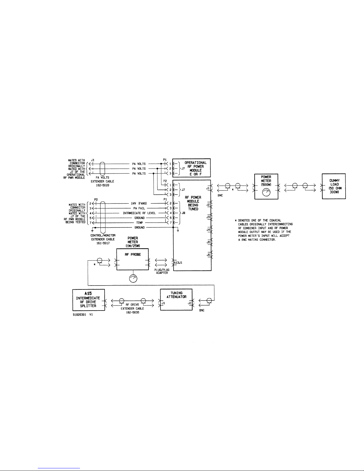
10 000 WATT FM BROADCAST TRANSMITTER
FM10
Figure 5-1 Test Interconnection for RF Power Module to be Tuned
Page 5-9
01 October 2002
Page 79
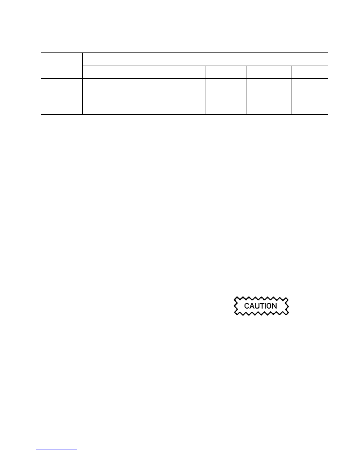
10 000 WATT FM BROADCAST TRANSMITTER
FM10
Table 5-4 Component Association for Tuning
COMPONENT POWER AMPLIFIER CHANNEL
1 2 3 4 5 6
INPUT PA A2 A4 A6 A8 A10 A12
OUTPUT PA A1 A3 A5 A7 A9 A11
TUNE SWITCH A13S2-1 A13S1-2 A13S1-1 A13S2-2 A13S3-1 A13S3-2
RF OUTPUT J1 J2 J3 J4 J5 J6
P2 of cable assembly 161-5017 mates with the
connector that was originally connected to J8 of
the removed RF power module.
- One end of the black, 8AWG ground wire in
cable assembly 161-5017 connects to the RF
power module's ground stud, using the studs'
original attaching hardware. The other end
connects to the rear of RF power module tray.
(e) Select either 'E' or 'F' RF power module as the
tuning PA volts source (for module to be tuned)
and then turn the module off by setting its PWR
MDL circuit breaker to off.
- Insert the PA volts extender cable between J7
of the RF power module ('E' or 'F') which was
turned off and the PA volts cableform
connector which mates with it.
NOTE
Do not connect P2 of the extender cable to J7 of the
RF power module to be tuned at this time.
- If the transmitter is on-air, restore the RF
contribution of the RF power module being
used as the PA volts source, by setting its PWR
MDL circuit breaker to on.
5.7.2.3 Tuning Procedure: Tune a repaired
input/output power amplifier after it has been reinstalled in its RF power module as follows:
NOTE
Reference is made to input/output power amplifier
pairs and an associated NORMAL/TUNE switch in
the following procedures. Refer to table 5-4 to
identify which components are associated with a
power amplifier channel, noting there are six
channels. If necessary, refer to the assembly detail
illustrations in the RF power module's service
instruction manual to identify/locate a specific
component.
The metal covers for the input/output power
amplifiers must be installed and their attaching
hardware firmly tightened during tuning
procedures.
(a) Using a digital multimeter, measure the DC
voltage between TP1 of the PA switching
power supply associated with the RF power
module selected as the PA volts source and
chassis ground. It should be 45.0 VDC when
c is between 87.9MHz and 98.0MHz or 46.5
ƒ
VDC when ƒc is between 98.1MHz and
107.9MHz.
NOTE
The PA volts being applied to an RF power module
being tuned must be 45.0 VDC when ƒc is between
87.9MHz and 98.0MHz or 46.5 VDC when ƒc is
between 98.1MHz and 107.9MHz. Since the RF
output is a product of this voltage, it may be
necessary to increase or decrease the RF output
during tuning procedures.
An RF output in excess of 7000 watts may be
applied to the antenna system when five RF power
modules are operational and the PA volts is set to
45.0/46.5 VDC If 7000 watts exceeds the
maximum RF that can be applied to the antenna, It
will be necessary to connect the output of the
transmitter to a suitably rated dummy load during
tuning procedures.
(b) If requirements of step (a) are not met,
increase/decrease the RF output using the
TRANSMITTER OUTPUT POWER - RAISE and
LOWER switches until the pa volts is the
required level.
Page 5-10
01 October 2002
Page 80

10 000 WATT FM BROADCAST TRANSMITTER
FM10
(c) Turn off RF power module selected as the
tuning PA volts source in step (e) of para
5.7.2.2, by setting its
PWR MDL
circuit breaker
to off.
(d) Mate P2 of the PA volts extender cable with J7
of the RF power module to be tuned.
(e) Ensure all output power amplifiers to be tuned
will not produce an excessive RF output by
setting their variable capacitor (C3) fully
clockwise.
(f) Connect the test setup's RF power meter to the
output connector (J1, J2, J3, J4, J5 or J6) for
the input/output power amplifier pair to be
tuned, as depicted in figure 5-1.
(g) On the RF power module interface PWB of the
RF module being tuned, set the TUNE/NORMAL
switch associated with the input/output power
amplifier pair to be tuned to TUNE.
NOTE
The remaining
to
NORMAL
.
TUNE/NORMAL
If more than one switch is set to
switches must be set
TUNE
it may result in destruction of MOSFETS in the
associated power amplifiers.
(h) Install or verify a 25W element is installed in
the test input power meter and it is set to
measure forward power.
(i) Turn on RF power module selected as tuning
PA volts source [turned off in step (c)] by
setting its PWR MDL circuit breaker to on.
(j) Measure the forward power level of the RF
drive being applied to the PA TUNE input of the
RF power module to be tuned, as indicated by
the input power meter. Measurement should be
between 7.0 and 12.0 watts depending on the
frequency of the power module being tuned.
Refer to table 5-4A for the correct power level
and adjust A14R116 IPA VOLTS until the
power stated in table 5-4A is achieved.
(k) Set the power meter's element to measure
reflected power and determine the reflected
power level of the RF drive, as indicated by the
input power meter. Measurement should be
less than 1.0 watt.
Table 5-4A PA Voltage Versus Frequency
CARRIER FREQUENCY PA PWR IN
87.5 - 89.9 7.0
90.0 - 92.9 8.0
93.0 - 95.9 8.5
96.0 - 98.9 9.5
99.0 - 89.9 10.5
102.0 104.9 11.0
105.5 107.9 12.0
(l) If reading in step (k) is more than 1.0W, adjust
C1 of the input power amplifier for the power
amplifier channel being tuned (see table 5-4)
for a null, which should be less than 1.0W.
(m) Replace the input power meter's 25W element
with a 1.0W element that has been set to
monitor reflected power.
(n) Adjust C1 of the input PA being tuned for a
null, which must be less than 0.01W.
NOTE
If a 0.01W null is not obtainable, the problem may
be the inductance of L1 on the input power amplifier
,
being tuned. If necessary, change the inductance of
L1 by changing the spacing between one or more of
its turns. It may be necessary to remove the metal
cover from the power amplifier to adjust L1. It must
be replaced to finalize tuning. Occasionally, at
high-end centre frequencies, fully squeezing L1 will
not provide sufficient inductance to properly tune
the PA input PWB. In this case, L1 may be replaced
by a slightly larger inductance coil (Nautel Part #
161-1019-05), located in the ancillary kit.
(o) When a null (less than 0.01W) has been
obtained, the input PA tuning is satisfactory.
(p) Adjust C3 of the output power amplifier for the
power amplifier channel being tuned (see table
5-4) for a 300W output to the dummy load, as
indicated by the output power meter's forward
power reading.
(q) Repeat steps (n) thru (p) until their
requirements are met without further
adjustment.
(r) Turn off RF power module being tuned, by
setting the PWR MDL circuit breaker of the RF
power module selected as the tuning PA volts
source to off.
Page 5-11
01 October 2002
Page 81

10 000 WATT FM BROADCAST TRANSMITTER
FM10
(s) Set TUNE/NORMAL switch for the power
amplifier channel that was being tuned to
NORMAL.
(t) Repeat steps (f) thru (s) for each power
amplifier channel to be tuned.
5.7.2.4 Completion of Tuning: When RF power
module tuning procedures have been completed,
verify the PA volts source for the RF power module
that was being tuned is turned off and then disconnect
it from the test set-up.
NOTE
When the testing is complete and the extender cables
are no longer required, disconnect them and remove
the tuning shelf and restore the original wiring
interconnections.
(a) If the IPA volts were altered to set the PA input
power in step (j) of para.5.7.2.3, restore the
original IPA volts level by adjusting A14R116.
(b) If the RF power was altered to set the PA volts
level in step (b) of the paragraph 5.7.2.3,
restore the original PA volts level using
TRANSMITTER OUTPUT POWER - RAISE
LOWER switches.
and
(c) Install the repaired RF power module as
detailed in paragraph 5.7.3.
5.7.3 RF POWER AMPLIFIER MODULE
INSTALLATION: Install an RF power module as
follows:
(a) Verify requirements of paragraph 5.7 have been
completed and are being met.
(b) Refer to figure MD-1 to verify the reference
designation of the module being installed and to
figure MD-5 as an aid in locating the associated
PWR MDL circuit breaker.
(c) Verify the PWR MDL circuit breaker identified
in step (b) is set to OFF (down).
(d) Slide RF power module into its respective
support tray, from the front of the cabinet,
ensuring retaining studs, at rear of the module's
chassis, pass thru the access holes in the
support tray.
(e) Ensure the top panel at the rear of the
transmitter cabinet (refer to figure MD-2) has
been removed.
(f) Secure the RF power module to its support
tray, by attaching hardware (hexagon nuts and
washers) on its rear retaining studs.
NOTE
Ensure nuts are firmly tightened as the retaining
studs provide a ground for the module.
(g) Connect all nine mating connectors to J1 thru
J9 on the rear of the module to be installed.
When connecting cable mating connectors to J1
thru J6 and J9 on the rear of the RF power module
to be installed, ensure the mating connectors at the
RF power module end are installed first and those
at the combiner end (or splitter end, for J9) are
installed last.
(h) Identify cable connectors (prefixed by 'W')
mating with the associated RF power module
connectors J1 thru J6 and J9.
(i) Locate the corresponding cable connectors
(prefixed by 'W') at the intermediate RF drive
splitter end and connect them at the splitter end.
(j) Locate the corresponding cable connectors
(prefixed by 'W') at the combiner end and
connect them at the combiner end.
(k) Set the PWR MDL circuit breaker identified in
step (b) to ON (up).
(l) Ensure control/monitor panel's POWER
MODULE-ALARM
lamps are all off.
Momentarily depress ALARM RESET switch to
reset the PA FAIL ALARM LED if required.
(m) Momentarily depress the MODULE RESET
switch. Transmitter power shall return to the
desired setting.
(n) Install the top panel at the rear of the
transmitter cabinet.
Page 5-12
01 October 2002
Page 82

10 000 WATT FM BROADCAST TRANSMITTER
TEMPORARY REPLACEMENT OF IPA
MODULE WITH RF POWER MODULE
5.8
The transmitter can operate, at a reduced
power level, with the IPA module replaced by an
operational RF power module. Replace the IPA
module with an RF power module as follows:
The IPA module contains solid state devices that
may be damaged if they are subjected to excessive
heat or high voltage transients. Every effort must
be taken to ensure circuits are not overdriven and
they are not disconnected from their loads while
turned on.
(a) Press/release the control/monitor panel's RF
OFF switch.
(b) Turn off the exciter.
FM10
When disconnecting cable mating connectors from
J1 thru J6 or J9 on the rear of the RF power
module to be removed, ensure the mating
connectors at the combiner end or splitter end are
removed also.
(f) Locate the corresponding cables (prefixed by
'W') at the combiner end and disconnect them.
(g) Locate the corresponding cable (prefixed by
'W') at the splitter end and disconnect it.
(h) Disconnect all nine mating connectors from J1
thru J9 on the rear of the RF power module to
be removed.
(i) Remove attaching hardware (hexagon nuts and
washers) from rear retaining studs of RF power
module to be removed.
(c) Set MAIN POWER circuit breaker to OFF
(down). The circuit breaker panel's AC ON lamp
shall turn off.
5.8.1 RF POWER MODULE REMOVAL:
Remove the operational RF power module which
temporarily replaces the IPA module as follows:
(a) Verify requirements of paragraph 5.8 have been
completed and are being met.
(b) Refer to figure MD-1 to verify the reference
designation of the RF power module being
removed to replace the IPA module and to
figure MD-5 as an aid in locating the associated
PWR MDL circuit breaker.
(c) Set PWR MDL circuit breaker, identified in step
(b), to OFF (down).
(d) Gain access to the rear of the RF power
modules by removing the two air filter panels
on the rear of the transmitter (refer to figure
MD-2). Retain all securing hardware.
(e) Identify cables (prefixed by 'W') mating with
the associated RF power module connectors J1
thru J6.
(j) Carefully withdraw RF power module from the
front of the cabinet.
(k) Locate the PA TUNE switches on the power
module interface PWB (A13). Switch S1-1,
S1-2, S2-1 and S2-2 to the TUNE position
(away from the NORMAL position) as the
associated PAs are not used when the module is
used as an IPA. (Switch numbers as read on
switch)
(l) Disconnect wire #11 from TB1-13 on the
power module interface PWB (A13) and tyrap
securely to the RF power module's wiring
harness.
NOTE
When the replacement RF power module is no
longer required, ensure wire #11 is reconnected to
TB1-13 and switches reset to
NORMAL
on the power
module interface PWB (A13) before returning the
RF power module to its original location.
5.8.2 IPA MODULE REMOVAL: Remove a
defective IPA module as follows:
(a) Verify requirements of paragraphs 5.8 and
5.8.1 have been completed and are being met.
(b) Disconnect the following mating connectors on
the rear of the IPA module:
Page 5-13
01 October 2002
Page 83

10 000 WATT FM BROADCAST TRANSMITTER
FM10
FLOATING PA
CONNECTOR CONNECTOR
W37P1 J1
W38P1 J2
P41 J3
P4 J4
W40P2 J5
(c) Remove attaching hardware (hexagon nuts and
washers) from rear retaining studs of IPA
module.
(d) Carefully withdraw the IPA module from the
front of the cabinet.
NOTE
If a serviceable RF power module is available,
install it in place of the IPA module. If not, replace
the IPA module with one of the transmitter's existing
RF power modules. The removal procedure for an
RF power module is described in paragraph 5.8.1
and the installation of an RF power module in place
of the IPA module is described in paragraph 5.8.3.
FLOATING RF POWER MODULE
CONNECTOR CONNECTOR
P4 J8
P41 J7
W37P1 J5
W38P1 J6
(e) Locate the IPA Input Matching Assembly (182-
5015-**) provided with the ancillary kit.
NOTE
The IPA Input Matching Assembly consists of two
coaxial cables (W1) connected to a male BNC
connector (P1) on one end and a female BNC
connector (P2) on the other end.
(f) Connect P1 of the IPA Input Matching
Assembly to J9 of the IPA replacement RF
power module.
(g) Connect W40P2 to P2 of the IPA Input
Matching Assembly.
(e) Service defective IPA module using instructions
detailed in the IPA module's instruction booklet.
5.8.3 IPA REPLACEMENT/RF POWER
MODULE INSTALLATION: Install an RF power
module in place of the IPA module as follows:
(a) Verify requirements of paragraphs 5.8 thru
5.8.2 are completed and being met.
(b) Slide the IPA replacement RF power module
into the IPA module's support tray, from the
front of the cabinet, ensuring retaining studs, at
rear of the module chassis, pass through the
access holes in the support tray.
(c) Secure the IPA replacement RF power module
to its support tray, by attaching hardware
(hexagon nuts and washers) on its rear retaining
studs.
NOTE
Ensure nuts are firmly tightened as the retaining
studs provide a ground for the module.
(d) Connect the following mating connectors on the
rear of the IPA replacement module:
(h) Install the two air filter panels on the rear of the
transmitter cabinet.
(i) Set MAIN POWER circuit breaker to ON (up).
The circuit breaker panel's AC ON lamp shall
turn on.
(j) Turn on the exciter.
(k) Press/release the control/monitor panel's RF ON
switch.
NOTE
If an IPA input alarm occurs, increase the exciter's
output power slightly to compensate for added
cabling and increased mismatch.
CONTROL/MONITOR PWB REPLACEMENT/
ADJUSTMENT
5.9
Install and adjust a replacement control/
monitor PWB as follows:
(a) Press the control/monitor panel's RF OFF switch
and turn off the MAIN POWER and all PWR
MDL
(A thru F) and IPA circuit breakers.
(b) Remove the control/monitor PWB's protective
cover and retain all hardware.
Page 5-14
01 October 2002
Page 84

10 000 WATT FM BROADCAST TRANSMITTER
FM10
(c) Disconnect the remote control and status wiring
connected to TB1 and TB2. Disconnect all
mating plugs to the control/monitor PWB and
carefully remove all mounting hardware.
(d) Install the replacement control/monitor PWB
using the hardware removed in step (c).
Reconnect the mating plugs with their
associated connectors on the control/monitor
PWB and reconnect the remote control and
status wiring at TB1 and TB2.
NOTE
Ensure three 1.5 VDC batteries are installed in the
control/monitor PWB's battery holder (XBT1).
Refer to paragraph 4.10.1 for Control/Monitor
Backup Battery Installation.
(e) Simultaneously press the control/monitor
panel's OUTPUT POWER - RAISE and OUTPUT
POWER - LOWER
switches (resets the RF
output power to zero watts).
NOTE
It may be necessary to press the ALARM RESET
switch to clear any false alarms caused by the
latching alarm circuitry on the replacemen tPWB.
(j) Remove external power supply from P27-1 and
reconnect wire disconnected in step (g).
(k) Temporarily disconnect the 22 AWG white
wire in pin 2 of connector P24. Apply 1.0VDC
between P24-2 (+) and ground (-).
(l) Measure the DC voltage between A14U6-3 (+)
and ground (-). Adjust REFLD PWR
potentiometer A14R20 until the voltage
recorded as
High Reflected Power (A14U6-3)
in table 5-6 is obtained.
(m) Remove external power supply from P24-2 and
reconnect wire disconnected in step (k).
(n) Measure the DC voltage between A14U4-3 (+)
and ground (-). Adjust PA VOLTS
potentiometer A14R11 until the voltage
recorded as
PA Volts Max Adj (A14U4-3)
in
table 5-6 is obtained.
(o) Measure the DC voltage between A14U33-3
(+) and ground (-). Adjust IPA VOLTS
potentiometer A14R116 until the voltage
recorded as
IPA Volts Control
(A14TP4) in
table 5-6 is obtained.
(f) Measure the DC voltage between A14U36-8
(+) and ground (-). Adjust IPA OUTPUT
potentiometer A14R147 until the voltage
recorded as
Low Intermediate RF (A14U36-8)
in table 5-6 is obtained.
(g) Temporarily disconnect the 22 AWG white
wire in pin 1 of connector P27. Apply 1.0
VDC between P27-1 (+) and ground (-).
(h) Measure the DC voltage between A14U35-3
(+) and ground (-). Adjust FWD PWR
potentiometer A14R129 until the voltage
recorded as
Fwd Pwr Mon Adj (A14U35-3)
in
table 5-6 is obtained.
(i) Measure the DC voltage between A14U36-11
(+) and ground (-). Adjust LOW RF
potentiometer A14R151 until the voltage
recorded as
Low RF Mon Adj (A14U36-11)
in
table 5-6 is obtained.
(p) Measure the DC voltage between A14U36-5
(+) and ground (-). Adjust IPA REFLD
potentiometer A14R130 until the voltage
recorded as
IPA REFLD PWR THRESHOLD
(A14U36-5) in table 5-6 is obtained.
(q) Measure the DC voltage between A14U36-7
(+) and ground (-). Adjust IPA HIGH
potentiometer A14R138 until the voltage
recorded as
IPA HIGH PWR THRESHOLD
(A14U36-7) in table 5-6 is obtained.
(r) Install the control/monitor PWB's protective
cover using the hardware retained in step (b).
(s) Turn on the PWR MDL (A thru F) and IPA
circuit breakers and then press the
control/monitor panel's RF ON switch.
(t) Press the OUTPUT POWER - RAISE switch until
the RF output power is the desired operating
level.
Page 5-15
01 October 2002
Page 85

10 000 WATT FM BROADCAST TRANSMITTER
FM10
POWER SUPPLY CONTROL PWB
REPLACEMENT
5.10
Install a replacement power supply control
PWB as follows:
(a) Press the control/monitor panel's RF OFF switch
and turn off the MAIN POWER and all PWR
MDL (A thru F) and IPA circuit breakers.
(b) Disconnect all mating plugs to the power
supply control PWB and remove all mounting
hardware.
(c) Install the replacement power supply control
PWB using the hardware removed in step (b).
Reconnect the mating connector plugs with
their associated connectors on the PWB.
(d) Turn on the MAIN POWER and all PWR MDL (A
thru F) and IPA circuit breakers.
Simultaneously press the control/monitor
panel's OUTPUT POWER - RAISE and OUTPUT
POWER - LOWER switches (resets the RF
output power to zero watts).
(e) Press the control/monitor panel's RF ON switch.
NOTE
It may be necessary to press the ALARM RESET
switch to clear any alarms caused by the status of
alarm latching circuitry on the PWB.
(f) Press the OUTPUT POWER - RAISE switch until
the RF output power is the desired operating
level.
Page 5-16
01 October 2002
Page 86

10 000 WATT FM BROADCAST TRANSMITTER
FM10
Table 5-5 Fault Analysis - No RF Output or Reduced RF Output
ALARM LAMP STATUS PROBABLE CAUSE
RF ON
RF ON
PA FAIL on A fault condition exists in one or more of the RF power modules. See
and INTERLOCK OPEN off RF off selected. To restore normal operation, select RF ON.
off and INTERLOCK OPEN on To restore normal operation, close the external interlock switches.
paragraph 5.11.1 for trouble shooting procedure.
COMBINER MATCHING on A fault condition has occurred in the combiner assembly that has
resulted in an unacceptable impedance match at the combiner input.
As the combiner contains no user serviceable parts, consult the factory
for replacement/repair options.
COMBINER MATCHING and PA FAIL
on
COMBINER MATCHING on and any
three PA VDC FAIL PWR SPLY A
THRU F
MODULE RF DRIVE on and any
one PA VDC FAIL PWR SPLY A thru F
MODULE RF DRIVE on, COMBINER
MATCHING
PA VDC FAIL PWR SPLY A thru F
MODULE TEMP on and any one of PA
VDC FAIL PWR SPLY A thru F
MODULE TEMP on, COMBINER
MATCHING
PA VDC FAIL PWR SPLY A thru F
on and three or more of
on and three or more of
A fault condition exists in at least thirteen of the RF power amplifiers
causing an unacceptable match at the combiner. The detected forward
power level was too low for the PA supply voltage level being applied
to the RF power modules. See paragraph 5.11.1 for trouble shooting
information.
A fault condition has occurred which caused at least three of the RF
power modules PWR MDL circuit breakers to trip off. See paragraph
5.11.12 for trouble shooting information.
The RF drive level at the input to an RF power module has dropped to
an unacceptable level and the associated power supply has been
inhibited. See paragraph 5.11.2 for trouble shooting information.
The RF drive level at the input to at least three RF power modules has
dropped to an unacceptable level and the associated power supplies
have been inhibited. See para 5.11.2 for trouble shooting information.
Temperature inside one of the RF power modules has exceeded its preset threshold and its associated power supply has been inhibited. See
paragraph 5.11.3 for trouble shooting information.
Temperature inside at least three of the RF power modules have
exceeded their pre-set threshold and the associated power supplies
have been inhibited. See paragraph 5.11.3 for trouble shooting
information.
AC POWER PHASE on One or more of the AC power phases has failed. See paragraph 5.11.4
HIGH AC POWER on The AC power voltage has exceeded its pre-set threshold. See
LOW AC POWER on The AC power voltage has dropped to an unacceptable level. See
for trouble shooting information.
paragraph 5.11.5 for trouble shooting information.
paragraph 5.11.6 for trouble shooting information.
Page 5-17
01 October 2002
Page 87

10 000 WATT FM BROADCAST TRANSMITTER
FM10
Table 5-5 Fault Analysis - No RF Output or Reduced RF Output
ALARM LAMP STATUS PROBABLE CAUSE
REFLD PWR on The reflected power detected by the transmitters output power probe
has exceeded 100 watts and, if above 440 watts, the transmitter's
output power has been reduced by the protection circuitry to prevent
damage to the RF power amplifiers. See paragraph 5.11.7 for trouble
shooting information.
IPA INPUT
on
The power level at the RF output of the exciter was outside of its
operating window (less than 12 watts or more than 33 watts), as
detected by the IPA input power probe. See paragraph 5.11.8 for
trouble shooting information
IPA OUTPUT on The power level at the output of the IPA has dropped below the preset
.
threshold as detected by the intermediate RF drive splitter assembly.
See paragraph 5.11.9 for trouble shooting information.
IPA SWR on An impedance mismatch exists at the output of the intermediate RF
drive splitter assembly as detected by the forward/reflected power
probe of the intermediate RF drive splitter assembly. See paragraph
5.11.10 for trouble shooting information.
IPA TEMP on Temperature inside the IPA module has exceeded its preset threshold.
See paragraph 5.11.11 for trouble shooting information.
PA VDC FAIL PWR SPLY (one or more
of A thru F on)
The output voltage of the switching power supply indicated is/was in
excess of 55.0 VDC, the output voltage of the switching power supply
indicated is/was too low for the level of control voltage being applied
to the control circuitry of the supply or the temperature of the IPA
switching power supply heatsink is/was in excess of 98°C. See
paragraph 5.11.12 for trouble shooting information.
PWR SPLY FAIL IPA on The output voltage of the IPA switching power supply is/was in excess
FAN FAIL on One or more of the four DC fans located in the fan assemblies of the
RECTIFIER TEMPERATURE on The temperature of one or both of the rectifier assemblies (A2/A3)
of 55.0 VDC or the output voltage of the IPA switching power supply
is/was too low for the level of control voltage being applied to the
control circuitry of the supply. See paragraph 5.11.13 for trouble
shooting information.
power supply or one or more of the two DC fans located on the rear,
lower panel have failed to operate. See paragraph 5.11.14 for trouble
shooting information.
is/was in excess of 90°C. See paragraph 5.11.15 for trouble shooting
information.
Page 5-18
01 October 2002
Page 88

10 000 WATT FM BROADCAST TRANSMITTER
FM10
TROUBLE SHOOTING FRONT PANEL
ALARMS
5.11
The trouble shooting of front panel alarms
assumes that the transmitter has been operating
successfully before the alarm condition occurred.
The information in table 5-5 is keyed to illuminated
front panel alarm (red) lamps. Locate the offending
alarm lamp(s) and probable cause(s) in table 5-5 and
then refer to the appropriate trouble shooting
paragraph.
NOTE
Ensure alarm indications cannot be reset before
trouble shooting. If the transmitter is latched off
due to IPA SWR or reflected power alarms, press
the PROTECT RESET switch. If the power has been
reduced due to module trip alarms, attempt to reset
the associated PWR MDL circuit breaker and press
the MODULE RESET switch. If fault remains, the
transmitter will resume its alarm condition and
trouble shooting should begin. If the transmitter
returns to full power, the fault has been cleared.
Since the alarm indications are latching, the ALARM
RESET
will have to be pressed/released.
(b) If the control/monitor panel's PA FAIL lamp is
on or any RF power module PA alarm lamps
(Q1 thru Q6) are on, but no reduction in RF
output power has occurred, the alarm may have
been caused by defective circuitry in the
control/monitor PWB's module PA fail circuitry
or the associated RF power module's power
module interface PWB.
(c) Without removing cables, visually inspect PA
output cable(s) (W1 thru W36) associated with
the suspected PA fail lamp(s) in step (a), noting
W1 thru W6 correspond with PA 1 (Q1) thru 6
(Q6) on rf power module A, W7 thru W12 with
PA 1 (Q1) thru 6 (Q6) on RF power module B,
etc. A loose or damaged connection may cause
a PA fail alarm.
When disconnecting cable mating connectors from
J1 thru J6 on the rear of the RF power module to
be removed, ensure the mating connectors at the
combiner end are removed first.
5.11.1 PA FAIL ALARM: A PA (power
amplifier) FAIL alarm can occur if the DC input
current to an RF power amplifier falls below a preset
threshold. This may be caused by cabling faults on
the PA input or output or a defective FET. If more
than twelve PA failures exist, the transmitter output
power will be reduced to zero watts. Trouble shoot a
PA fail alarm as follows:
(a) Isolate the RF power module (A thru F)
associated with the PA FAIL alarm by opening
the control/monitor panel and noting which RF
power module(s) has active PA alarm lamps
(Q1 thru Q6). If more than twelve PA fail
lamps are on, verify the COMBINER MATCHING
alarm is also on and the transmitter has been
reduced to zero watts.
NOTE
If a fault condition exists in at least thirteen of the
RF power amplifiers causing an unacceptable match
at the combiner (detected forward power level was
too low for the PA supply voltage level being
applied to the RF power modules), the COMBINER
MATCHING alarm lamp will turn on.
(d) To remove the PA output cable(s), turn off the
RF power module's associated PWR MDL circuit
breaker, then disconnect the PA output cable
from the combiner end first. Perform a
continuity check on the cable's center conductor
and shield.
(e) If the PA output cables checked in step (d) are
not defective, the problem may exist within the
associated RF power module,
(f) Trouble shoot the associated RF power module
as described in paragraph 5.7.
5.11.2 MODULE RF DRIVE ALARM: A
MODULE RF DRIVE alarm can occur if the RF drive
level at the input to an RF power module
(intermediate RF drive) drops to an unacceptable
level. The associated switching power supply will
also be inhibited, and therefore, a PA VDC FAIL - PWR
SPLY alarm (A thru F) will also occur as well as a
reduction in RF output power. If this affects three or
more RF power modules, a COMBINER MATCHING
alarm should also occur and the transmitter will be
inhibited. Trouble shoot a module RF drive alarm as
follows:
Page 5-19
01 October 2002
Page 89

10 000 WATT FM BROADCAST TRANSMITTER
FM10
NOTE
Following each trouble shooting action taken on the
MODULE RF DRIVE alarm, press MODULE RESET
and ALARM RESET switches. If three or more RF
power modules have been inhibited, it will also be
necessary to press/release the PROTECT RESET
switch. If the MODULE RF DRIVE alarm(s) cannot be
reset, the fault remains and trouble shooting should
continue. If transmitter operation is restored to the
desired power level, the fault has been cleared.
(a) Note which PA VDC - PWR SPLY lamp(s) (
thru F) has turned on. The transmitter output
power should have been reduced (or inhibited depending on the number of failures).
(b) A sample of each RF power module's
intermediate RF drive level is applied to J5-7
thru J5-12 (RF power module A thru F
respectively) of the control/monitor PWB
(A14). Measure the voltage between the
associated J5 pin(s) on the control/monitor
PWB and ground.
(c) If one or more of the digital multimeter readings
are not near the voltages recorded as
Intermediate RF Level (A thru F)
in table 5-6,
check the appropriate cables and connectors
between the intermediate RF drive splitter
(A15) and the associated RF power module's
input.
NOTE
If it is necessary to check the control/monitorPWB's
intermediate RF level monitor circuitry, refer to the
control/monitor PWB's service instruction manual
and the trouble shooting data in section 7 of this
manual to isolate circuit defects.
5.11.3 MODULE TEMP ALARM: A
MODULE TEMP alarm can occur if the
temperature sensed within an RF power module
exceeds 85°C due to a failed RF power module fan or
A
a blockage in the RF power module's normal air flow.
The associated switching power supply will also be
inhibited, and therefore, a PA VDC FAIL - PWR SPLY
alarm (A thru F) will also occur, as well as a
reduction in RF output power. If this affects three or
more RF power modules, a COMBINER MATCHING
alarm should also occur and the transmitter will be
inhibited. Trouble shoot a module temperature alarm
as follows:
NOTE
Following each trouble shooting action taken on the
MODULE TEMP alarm, press MODULE RESET and
ALARM RESET switches. If three or more RF
POWER MODULES have been inhibited, it will also
be necessary to press the PROTECT RESET switch.
If the MODULE TEMP ALARM(s) cannot be reset, the
fault remains and trouble shooting should continue.
If transmitter operation is restored to the desired
power level, the fault has been cleared.
(d) If the cables and connectors from step (c) are
operational, a problem may exist within the
associated RF power module's power module
interface PWB. Refer to the RF power
module's service instruction manual.
(e) If the multimeter readings from step (b) are
near the level determined in step (c), the
control/monitor PWB's intermediate RF level
monitor circuitry may be defective.
(a) Note which PA VDC - PWR SPLY lamps (A thru
F) has turned on. The transmitter output power
should have been reduced (or inhibited depending on the number of failures). It is
probable an excessively high temperature
occurred in an RF power module.
Ensure a module has had sufficient time to cool off
before proceeding.
(b) Check fan fuses F3 thru F5 on the low voltage
power supply PWB (A26A1) by measuring the
voltage across them. An open fuse will cause
two RF power module fans to turn off. If a
fuse has become open circuit, replace it and
monitor for recurrence.
Page 5-20
01 October 2002
Page 90

10 000 WATT FM BROADCAST TRANSMITTER
FM10
(c) Check for air flow out of the front of the
module and perform a visual inspection for fan
blockage. If a blockage exists, it will be
necessary to remove the RF power module and
clean the obstructed air path or replace the fan,
as required. Verify 24 VDC is present on pin 2
of the connector which normally mates with J8
of the RF power module, to isolate a possible
wiring defect.
(d) Once the RF power module is removed,
measure resistance of temperature sensing
thermistor RT1, located on the top of the
module. If the RF power module has
sufficiently cooled, the resistance should be
near 200 kilohms.
(e) If the resistance reading from step (d) is near
the value specified, the control/monitor PWB's
power module temperature monitor circuitry
may be defective.
NOTE
If it is necessary to check the control/monitor PWB's
power module temperature monitor circuitry, refer
to the control/monitor PWB's service instruction
manual and the trouble shooting data in section 7 of
this manual to isolate circuit defects.
5.11.4 AC PHASE ALARM: An AC PHASE
alarm can occur due to one or more of the AC input
power phases failing, a wiring fault or defective
components on the low voltage power supply PWB.
If the transmitter RF output has been inhibited, the
fault remains. If the transmitter RF output has been
restored, the alarm was probably caused by a power
fluctuation at the AC power service entrance and
ALARM RESET
should be pressed to clear the alarm
indication. Trouble shoot an AC phase alarm as
follows:
NOTE
An AC phase alarm may cause an AC PHASE or a
LOW AC PWR
alarm lamp to turn on. Attempt to
confirm an AC phase alarm by pressing the ALARM
RESET switch. If the LOW AC PWR alarm lamp
turns off and the AC PHASE alarm lamp turns on,
continue trouble shooting. If not, see paragraph
5.11.6.
NOTE
Random alarm occurrences can result from
fluctuations of the AC line voltage at the service
entrance. Monitor the AC line voltage and contact
the power company.
(a) Measure the AC voltage, representative of an
AC phase, between TB1-1 of the low voltage
power supply (A26) and ground. Repeat for
the other two phases on TB1-2 and TB1-3.
(b) If a voltage is not present on one or more of the
terminals measured in step (a), it is probable
that a phase has been lost to the power
transformer's primary. Check the AC power
source.
(c) If a voltage is present on all three terminals
measured in step (a), check fuses F1, F2 and F3
on the low voltage power supply (A26). If the
fuses are not open circuit, suspect a defective
component on the low voltage power supply
PWB or the control/monitor PWB.
NOTE
If it is necessary to check the three-phase monitor
PWB's phase loss monitor circuitry, refer to SD-5
and the trouble shooting data in section 7 of this
manual to isolate circuit defects. If it is necessary
to check the control/monitor PWB refer to the
control/monitor PWB's service instruction manual
and the trouble shooting data in section 7.
5.11.5 HIGH AC PWR ALARM: A HIGH AC
PWR
alarm can occur if the unregulated 24 VDC,
which is representative of the AC line voltage,
exceeds a pre-set threshold due to AC mains
exceeding the normal level by at least ten percent or
defective components on the control/monitor PWB.
If the transmitter's RF output has been inhibited, the
fault remains. If the transmitter's RF output has been
restored, the alarm was probably caused by a power
fluctuation at the AC power service entrance and
ALARM RESET should be pressed to clear the alarm
indication. Trouble shoot a high AC power alarm as
follows:
Page 5-21
01 October 2002
Page 91

10 000 WATT FM BROADCAST TRANSMITTER
FM10
NOTE
Random alarm occurrences can result from AC line
voltage fluctuations at the service entrance.
Monitor the AC line voltage and contact the power
company.
(a) Measure the voltage between J2-12 (+) of the
low voltage power supply PWB (A26A1),
representative of the AC line voltage, and
ground (-).
(b) If the voltage measured in step (a) is nominally
27.8 VDC or greater, then the AC line voltage
has exceeded its preset high AC threshold.
Verify the tap selection on the power
transformer is correct and, if so, then it is
probable that the AC mains are too high.
(c) If the voltage measured in step (a) is within
acceptable limits, it is probable that a problem
exists with the AC supply monitoring circuitry
on the control/monitor PWB.
NOTE
If it is necessary to check the control/monitor PWB's
AC supply monitor circuitry, refer to the control/
monitor PWB's service instruction manual and the
trouble shooting data in section 7 of this manual to
isolate circuit defects.
5.11.6 LOW AC PWR ALARM: A LOW AC
PWR
alarm can occur if the unregulated 24 VDC,
representative of the AC line voltage, falls below a
preset threshold due to AC mains falling at least ten
percent below the normal level. If the transmitter's
RF output has been inhibited, the fault remains. If
the transmitter's RF output has been restored, the
alarm was probably caused by a power fluctuation at
the AC power service entrance and ALARM RESET
should be pressed to clear the alarm indication.
Trouble shoot a low AC power alarm as follows:
NOTE
Random alarm occurrences can result from AC line
voltage fluctuations at the service entrance.
Monitor the AC line voltage and contact the power
company.
(a) Ensure the LOW AC PWR lamp was not caused
by an AC phase alarm by pressing the ALARM
RESET
switch. If the LOW AC PWR lamp turns
off and the AC PHASE lamp turns on, a phase
loss may have occurred (see paragraph 5.11.4).
(b) Measure the voltage between J2-12 (+) of the
low voltage power supply PWB (A26A1),
representative of the AC line voltage, and
ground (-).
(c) If the voltage measured in step (b) is nominally
19.0 VDC or less, then the AC line voltage has
fallen below its preset low AC threshold.
Verify the tap selection on the power
transformer is correct and, if so, then it is
probable that the AC mains are too low.
(d) If the voltage measured in step (b) is within
acceptable limits, it is probable that a problem
exists with the AC supply monitoring circuitry
on the control/monitor PWB.
NOTE
If it is necessary to check the control/monitor PWB's
AC supply monitor circuitry, refer to the control/
monitor PWB's service instruction manual and the
trouble shooting data in section 7 of this manual to
isolate circuit defects.
5.11.7 REFLECTED POWER ALARM: A
reflected power alarm can occur if the reflected
power at the transmitter's output exceeds a preset
threshold or if a fault occurs in the control/ monitor
PWB's reflected power detection circuitry. The
severity of the reflected power level and the
subsequent condition of the transmitter's RF output
aids in trouble shooting the cause of the fault.
Trouble shoot a reflected power alarm as follows:
(a) Note the control/monitor panel's reflected and
forward power readings by setting the
FORWARD/REFLECTED switch to either
REFLECTED
or FORWARD.
(b) Based on the meter readings in step (a), refer to
the applicable paragraph (5.11.7.1 thru
5.11.7.3) to determine the probable cause and
trouble shooting information.
5.11.7.1 Reflected and Forward Power Zero
Watts: If the REFLECTED POWER indication is near
zero watts and the FORWARD POWER indication is
zero watts, the transmitter's RF output has been
inhibited due to:
Page 5-22
01 October 2002
Page 92

10 000 WATT FM BROADCAST TRANSMITTER
FM10
- At least four transient SWR conditions, in
excess of 2:1 (1220 watts), were detected
within a five second time interval indicating
arcing or lightning strikes.
- A continually degrading match has caused a
reduction in the transmitter's forward power to
maintain operation. The severity of the
mismatch has reduced the forward power below
1500 watts and the transmitter cannot operate
reliably.
(a) Verify the cause of the mismatch and/or
transient SWR condition has been removed.
Press the control/monitor panel's PROTECT
RESET
switch. If the cause of the alarm has
been cleared, the transmitter should resume
operation. Press ALARM RESET.
5.11.7.2 Reflected Power Zero Watts and
Forward Power Normal: If the REFLECTED
POWER
FORWARD POWER
indication is near zero watts and the
indication reads the normal
operating power level:
- a 2:1 SWR transient has probably occurred due
to an arc or lightning, but not frequently enough
to cause a shutdown. Press ALARM RESET.
(a) If the problem persists and there is no evidence
of lightning, suspect arcing or another transient
fault within the antenna system. If no arcing or
other intermittent antenna system faults can be
found, a problem may exist with the
control/monitor PWB's reflected power
detection circuitry.
(b) If the external reflected power meter's reading
is near zero watts, a problem may exist with the
control/monitor PWB's reflected power
detection circuitry.
(c) If the FORWARD POWER indication is near the
normal operating level and no reflected power
cutbacks have occurred, the reflected power
level has not exceeded the cutback threshold of
440 watts.
NOTE
When the reflected power exceeds 100 watts, the
transmitter's ALC (automatic level control) circuit is
disabled. This may account for some variation in
the forward power level.
(d) If the forward power has been reduced, it is
probable the RF load impedance is not
optimum (50-ohms) and the reflected power has
exceeded 440 watts (but not 1220 watts). The
forward power will have been cutback
(reduced), by an incremental forward power
reduction protection circuit, to maintain the
reflected power at less than 440 watts. The
degree of RF load impedance mismatch
determines the number of increments (up to 32)
that are required to ensure the reflected power
does not exceed 440 watts. If the forward
power is reduced to a nominal 1500 watts and
the reflected power is still in excess of 440
watts, the RF output will shutback (turn off)
and remained latched in this state until the
protection circuits are manually reset (locally or
remotely as appropriate).
NOTE
If it is necessary to check the control/monitor PWB's
reflected power detection circuitry, refer to the
control/monitor PWB’s service instruction manual
to isolate circuit defects.
5.11.7.3 Reflected Power Between 100 and 440
Watts: If the REFLECTED POWER indication is
between 100 and 440 watts, excessive SWR may
exist at the transmitter output.
(a) If an external reflected power meter is
available, verify its reading is similar to that on
the control/monitor panel.
(e) Perform a visual inspection around the
transmitter output (including antenna). If there
is an obvious reason for the mismatch, attempt
to correct it.
NOTE
Fault causes at the transmitter's RF output may
include antenna icing, intermittent or defective feed
cable/RF connections or a defective antenna.
Random alarms may be caused by arcing of the RF
feed cable or lightning discharges.
Page 5-23
01 October 2002
Page 93

10 000 WATT FM BROADCAST TRANSMITTER
FM10
(f) If no cause for the mismatch can be located in
the antenna system or RF feed cable, suspect a
problem with the control/monitor PWB's
reflected power detection circuitry. This may
be supported by the findings in step (b).
NOTE
If it is necessary to check the control/monitor PWB's
reflected power detection circuitry, refer to the
control/monitor PWB's service instruction manual
to isolate circuit defects.
5.11.8 IPA INPUT ALARM: An IPA input
alarm can occur due to the input RF drive level
(exciter power) to the IPA module exceeding or
falling below the preset range due to an exciter fault,
excessive load variation on the exciter output, wiring
fault or defective components on the control/monitor
PWB or IPA input power probe. Trouble shoot an
IPA input alarm as follows:
NOTE
Following each discrete trouble shooting paragraph
of the IPA input alarm, press the ALARM RESET
switch. If the alarm lamp is still on, the fault
remains and trouble shooting should continue at the
next paragraph. If transmitter operation is restored
and the alarm lamp turns off, the fault has been
cleared.
5.11.8.1 Exciter ALC Check:
(a) At initial turn on (RF ON), the input impedance
of the IPA module (normally 50 ohms) varies
such that the exciter output may be reduced. If
the exciter has an automatic level control
(ALC) circuit, verify it has been enabled. An
ALC circuit will reduce the effect of load
variation on the exciter output.
5.11.8.2 Cables/Connections:
(a) Check for loose or damaged connections
between the exciter output and J1 of the IPA
input power probe (A16). If necessary, replace
or repair any damaged connections/ cabling
using suitable coaxial cable (50 ohm, near 0.68
dielectric constant material).
5.11.8.3 RF Drive Checks:
(a) Read the exciter's forward power meter. If the
forward power is:
- stable and less than 12 watts, see paragraph
5.11.8.3.1 'Low RF Drive'.
- reaching an acceptable level, but continually
dropping to zero watts, see paragraph
5.11.8.3.2 'Exciter Output Load Fluctuation'.
- fluctuating and greater than 33 watts, see
paragraph 5.11.8.3.3 'High RF Drive'.
- stable and within acceptable limits (12 to 33
watts), measure the RF drive sample voltage at
TP7 of the control/monitor PWB (A14). If it is
near the
RF Drive Level [___ Fwd Pwr]
specified in table 5-6, check the RF drive
monitor protection circuitry on the control/
monitor PWB. If not, suspect a defective
component in IPA input power probe A16.
NOTE
If it is necessary to check the control/monitor PWB's
RF drive monitor circuitry, refer to the control/
monitor PWB's service instruction manual and the
trouble shooting data in section 7 of this manual to
isolate circuit defects.
5.11.8.3.1
Low RF Drive
: The exciter power has
probably fallen below the low RF drive threshold
(nominally 12 watts). Increase the exciter output
power until the voltage at A14TP7, representative of
the RF drive level, is the level specified as
Level [RF Off]
5.11.8.3.2
in table 5-6.
Exciter Output Load Fluctuation
RF Drive
: The
exciter's load may vary when the IPA power supply
is enabled (RF ON is initiated) and cause the exciter's
output power to be reduced. Try increasing the
length of cable between J2 of the IPA input power
probe (A16) and J5 of the IPA module (A17) by six
or twelve inches. This will add approximately 30 or
60 degrees of electrical length and may reduce the
effect of load fluctuation at the exciter output.
Page 5-24
01 October 2002
Page 94

10 000 WATT FM BROADCAST TRANSMITTER
FM10
5.11.8.3.3
High RF Drive
: The exciter power has
probably exceeded the high RF drive threshold
(nominally 33 watts). Decrease the exciter output
power until the voltage at A14TP7, representative of
the RF drive level, is the level specified as
Level [___ Fwd Pwr]
in table 5-6.
RF Drive
NOTE
The control/monitor PWB's RF drive monitor
circuitry generates an exciter interlock control
signal to mute the exciter's RF output for a nominal
five second interval. This signal is generated each
time the exciter's output exceeds 33 watts.
5.11.9 IPA OUTPUT ALARM: An IPA
OUTPUT alarm can occur if the average detected RF
level at the combiner splitter of the RF power
modules falls below a preset threshold. Trouble
shoot an IPA output alarm as follows:
5.11.9.1 IPA Module Low Supply Voltage
Check: Determine whether the IPA switching power
supply's output voltage is too low as follows:
(a) Set the control/monitor panel's DC SUPPLY-
Volts switch to IPA.
5.11.9.3 Control/Monitor PWB IPA Output
Monitor Check: Determine whether the
control/monitor PWB's
IPA Output
circuit is
defective as follows:
(a) Measure the DC voltage between TP5 (+) on
the control monitor PWB (A14) and ground (-).
Record the meter reading.
(b) If the digital multimeter reading is not near the
voltage recorded as
IPA Fwd Pwr Level
in
table 5-6, check the cables and connectors
between the six-way splitter and the IPA
module.
NOTE
If the transmitter RF output is inhibited, use the
VDC set for minimum]
operating normally, use the
Assigned FWD PWR]
values for TP5. If it is
[PA VDC set for
value.
[PA
(c) If the reading in (a) is not near the level
determined in step (b), the control/monitor
PWB's circuitry may be defective. To trouble
shoot the circuitry, refer to the control/ monitor
PWB's service instruction manual.
(b) Monitor the IPA power supply's output voltage
on control/monitor panel's DC SUPPLY-Volts
meter. Record the meter reading.
(c) If the meter reading in step (b) is not near the
voltages recorded as
IPA VDC
in table 5-6
Factory Determined Measurements for
Critical Parameters
, the IPA power supply
requires adjustment or has failed.
(d) If the meter reading in step (b) is near 0.0 VDC
and the PWR SPLY FAIL IPA lamp is not on (see
paragraph 5.11.13), it is probable that a power
amplifier in the IPA module has failed.
5.11.9.2 IPA Module Replacement: Replace the
IPA module as follows:
(a) Temporarily replace the IPA module with an
operational RF power module as detailed in
paragraph 5.8.
(b) Trouble shoot the IPA module as detailed in the
IPA module's service instruction manual.
5.11.10 IPA SWR ALARM: An IPA SWR alarm
can occur when the forward or reflected power of the
IPA module level exceeds a preset threshold.
Remedial action on an IPA SWR alarm should be
taken as follows:
5.11.10.1 IPA Reflected Power: Determine whether
an excessive IPA reflected power level caused the
alarm as follows:
(a) If the IPA SWR alarm is on and the transmitter
has not been latched off, check cables between
the IPA combiner/splitter probe's output and
the RF power module inputs for loose
connectors and intermittent cabling.
(b) If the IPA SWR alarm is on and the transmitter
has been latched off, check for open or short
circuit on the cables between the IPA combiner/
splitter probe's output and the RF power
module inputs. Press PROTECT RESET. If the
fault has cleared, the transmitter will resume
operation.
Page 5-25
01 October 2002
Page 95

10 000 WATT FM BROADCAST TRANSMITTER
FM10
NOTE
If one of the six-way splitter's cables has open or
short circuited, the associated RF power module's
switching power supply will be inhibited due to low
RF drive input level and the MODULE RF DRIVE and
associated PA VDC FAIL PWR SPLY lamp shall be
on.
(c) If the transmitter has not been latched off,
verify the voltage on U33-7 of the control/
monitor PWB is near that recorded as
Refld Pwr Level
in table 5-6.
IPA
5.11.10.2 IPA Forward Power: Determine whether
an excessive IPA forward power level caused the
alarm as follows:
(a) If the IPA SWR alarm is on and the transmitter
has not been latched off, check cables between
the IPA combiner/splitter probe's output and
the RF power module inputs.
(b) If the IPA SWR alarm is on and the transmitter
has been latched off, check for an open or short
circuit on the cables between the six-way
combiner splitter and the RF power module
inputs.
NOTE
If one of the six-way combiner/splitter cables has
open or short circuited, the associated RF power
module's switching power supply will be inhibited
due to low RF drive input and the MODULE RF
DRIVE lamp and associated PA VDC FAIL PWR SPLY
lamp shall be on.
NOTE
Following each trouble shooting action taken on the
IPA TEMP alarm, press the ALARM RESET switch. If
the alarm lamp turns off, the fault has been cleared.
If the alarm lamp remains on, trouble shooting
should continue.
(a) Check fan fuse F2 on the low voltage power
supply PWB (A26A1) by measuring the voltage
across it. An open fuse will cause the IPA module's
fan to turn off. If a fuse has become open circuit,
replace it and monitor for recurrence.
Since the IPA is not inhibited during an
IPA TEMP
alarm, the temperature of the IPA module may be
in excess of 73°°C. Use extreme care when
inspecting its air path and cooling fan.
(b) Perform a visual inspection of the IPA module
for fan blockage. Check for air flow out of the
front of the module. If a blockage exists, it will
be necessary to remove the IPA module and
clean the obstructed air path or replace the fan,
as required. Verify 24 VDC is on P4-1
(normally mates with J4 of the IPA module) to
isolate a possible wiring defect.
NOTE
The IPA module may be temporarily replaced by an
RF power module while the IPA module is being
serviced. Refer to paragraph 5.8 to replace the IPA
module with an operational RF power module.
(c) If the cables in steps (a) and (b) are not short
circuited and the transmitter is still latched off,
check the low voltage power supply PWB as
detailed in this instruction manual.
5.11.11 IPA TEMP ALARM: An IPA TEMP alarm
can occur if the temperature sensed within the IPA
module exceeds 73°C due to a failed IPA module fan
or a blockage in the normal air flow. The
transmitter's RF output should not be affected by this
alarm, nor should the IPA switching power supply be
inhibited or tripped off by its associated PWR MDL
circuit breaker. Trouble shoot an IPA temperature
alarm as follows:
(c) Once the IPA module has been removed,
measure the resistance of temperature sensing
thermistor RT1, located on top of the module.
If the IPA module has sufficiently cooled
(25°C), the resistance should be near 200K
ohms.
(d) If the resistance measured in step (c) is near the
value specified, the control/monitor PWB's IPA
module temperature circuitry may be defective.
Page 5-26
01 October 2002
Page 96

10 000 WATT FM BROADCAST TRANSMITTER
FM10
NOTE
If it is necessary to check the control/monitor PWB's
IPA module temperature circuitry, refer to the
control/monitor PWB's service instruction manual
and the trouble shooting data in section 7 of this
manual to isolate circuit defects.
5.11.12 IPA VDC FAIL PWR SPLY (A thru F)
ALARM: A PA VDC FAIL PWR SPLY alarm can
occur if the output voltage of the switching power
supply indicated is/was in excess of 55.0 VDC, the
output voltage of the switching power supply
indicated is/was too low for the level of control
voltage being applied to the control circuitry of the
supply or the temperature of the switching power
supply heatsink indicated is/was in excess of 98°C.
Trouble shoot a PA VDC FAIL PWR SPLY alarm as
follows:
(a) If the circuit breaker for the associated
switching power supply has not tripped off, it is
probable that the alarm was triggered due to a
low output from the supply in question. Refer
to paragraph 5.11.12.1 to trouble shoot this
failure condition.
(c) If the switching power supply module's output
voltage is normal, a possible fault exists in the
power supply control PWB's low PA volts
detection circuitry.
NOTE
If it is necessary to check the power supply control
PWB's low PA volts detection circuitry, refer to the
power supply control PWB's service instruction
manual and the trouble shooting data in section 7 of
this manual to isolate circuit defects.
5.11.12.2 High Supply Output/High Supply
Temp: Trouble shoot a switching power supply
module for a high output or high temperature by
checking the following:
(a) Attempt to reset the associated switching power
supply's circuit breaker.
(b) If the circuit breaker cannot be reset, proceed to
step (f). If the circuit breaker can be reset and
all alarms reset, it is probable that the alarm
was triggered due to an excessive temperature
in the switching power supply module.
(b) If the circuit breaker for the associated
switching power supply has tripped off, it is
probable that the alarm was triggered due to an
excessive output from the supply in question or
the allowable operating temperature was
exceeded. Refer to paragraph 5.11.12.2 to
trouble shoot these failure conditions.
5.11.12.1 Low Supply Output: Trouble shoot a
switching power supply module for a low output by
checking the following:
(a) Using a digital voltmeter, measure the output
voltage of the suspect supply at the test point
(TP1) provided on the supply.
(b) The reading obtained in step (a) can be
compared to that of the other switching power
supply modules to see if it is unacceptably low.
Compare the reading obtained in step (a) with
the voltage recorded as
set to Assigned Level]
PA VDC [FWD PWR
in table 5-6. If these
readings do not coincide, refer to the switching
power supply module's service instruction
manual for replacement or repair instructions.
(c) Check for air flow out of the top of the supply
in question.
(d) Allow the system to run to see if the alarm
reoccurs. If the alarm reoccurs and all other
switching power supply modules continue to
operate, refer to the switching power supply
module's service instruction manual for
replacement or repair instructions.
(e) If, after replacing/repairing the faulty switching
power supply module, the alarm continues to
occur, a possible fault exists in the power
supply control PWB's high PA volts detection
circuitry.
NOTE
If it is necessary to check the power supply control
PWB's high PA volts detection circuitry, refer to the
power supply control PWB's service instruction
manual and the trouble shooting data in section 7 of
this manual to isolate circuit defects.
Page 5-27
01 October 2002
Page 97

10 000 WATT FM BROADCAST TRANSMITTER
FM10
(f) Since the circuit breaker could not be reset, it is
probable that the alarm was triggered due to an
excessively high output from the associated
power supply module. Refer to the switching
power supply module's service instruction
manual for replacement or repair instructions.
(g) If, after replacing/repairing the faulty switching
power supply module, the alarm continues to
occur, refer to the power supply control PWB
service instruction manual for replacement or
repair.
5.11.13 PWR SPLY FAIL IPA ALARM: A
PWR SPLY FAIL IPA alarm can occur if the output
voltage of the IPA switching power supply is/was in
excess of 51 VDC or the output voltage of the IPA
switching power supply is/was too low for the control
voltage level being applied to its control circuit.
Trouble shoot a PWR SPLY FAIL IPA alarm as
follows:
(a) If the circuit breaker for the IPA switching
power supply has not tripped off, it is probable
the alarm was triggered due to a low output
from the supply or the allowable operating
temperature was exceeded. Refer to paragraph
5.11.13.1 to trouble shoot these failure
conditions.
(b) If the circuit breaker for the IPA switching
power supply has tripped off, it is probable the
alarm was triggered due to an excessive output
from the IPA supply. Refer to paragraph
5.11.13.2 to trouble shoot this failure condition.
5.11.13.1 Low IPA Supply Output: Trouble
shoot the IPA switching power supply module for a
low output by checking the following:
(a) Using a digital voltmeter, measure the output
voltage of the IPA supply at the test point
(TP1) provided on the supply.
(b) Compare the reading obtained in step (a) with
the voltage recorded as
IPA VDC
in table 5-6.
If these readings do not coincide, refer to the
switching power supply modules service
instruction manual for replacement or repair
instructions.
(c) Allow the system to run to see if the alarm
reoccurs. If the alarm reoccurs, refer to the
switching power supply module's service
instruction manual for replacement or repair
instructions.
(d) If, after replacing/repairing the IPA switching
power supply module, the alarm continues to
occur, a possible defect exists in the power
supply control PWB's low IPA volts detection
circuitry.
NOTE
If it is necessary to check the power supply control
PWB's low IPA volts detection circuitry, refer to the
power supply control PWB's service instruction
manual and the trouble shooting data in section 7 of
this manual to isolate circuit defects.
5.11.13.2 High IPA Supply Output: Trouble
shoot the IPA switching power supply module for a
high output by checking the following:
(a) Attempt to reset the associated switching power
supply's circuit breaker.
(b) If the circuit breaker cannot be reset, it is
probable that the alarm was triggered due to an
excessively high output from the IPA power
supply module. Refer to the switching power
supply module's service instruction manual for
replacement or repair instructions.
(c) If, after replacing/repairing the IPA switching
power supply, the alarm continues to occur,
refer to the power supply control PWB service
instruction manual for replacement or repair.
5.11.14 FAN FAIL ALARM: A fan fail alarm
can occur due to the failure of one or more of the DC
fans located in the fan assemblies (A27 and A28) or
on the rear, lower panel. A pulse train, representative
of each fan's speed, is monitored by the power supply
control PWB's fan monitor circuitry. If one or more
of these fans stall or fail, a local and remote FAN
FAIL alarm will be generated. Trouble shoot a fan
fail alarm as follows:
Page 5-28
01 October 2002
Page 98
10 000 WATT FM BROADCAST TRANSMITTER
FM10
(a) Perform a visual inspection on the power
supply fan assemblies (A27 and A28) or the
rear, lower panel for fan blockage. If a
blockage exists, it will be necessary to remove
the fan assembly or lower, rear panel and clean
the obstructed air path or replace the fan, as
required.
WARNING
Dangerous voltages exist on terminals of power
transformer A1T1. Ensure the
circuit breaker is turned
OFF
remove a fan assembly or the rear, lower panel.
(b) Check fan fuses F6, F7 and F1 located on the
low voltage power supply PWB (A26A1). An
open circuit F6 or F7 will cause both fans in
the associated fan assembly to turn off. An
open circuit F1 will cause both fans on the rear,
lower panel to turn off.
5.11.15 RECTIFIER TEMPERATURE
ALARM: A rectifier temperature alarm can occur if
the temperature of one of the rectifier assemblies (A2
or A3) exceeds 90°C. Trouble shoot a rectifier
temperature alarm as follows:
MAIN POWER
before attempting to
AIR FILTERS
5.12
Air filters should be inspected and cleaned
periodically using soap and warm water. If the air
filters become damaged, they should be replaced as
soon as possible.
NOTE
Two types of air cooling are available for use with
the FM10. In an open air system, the transmitter
will contain four air filters, located in the rear
(Nautel part number - HR51). In a closed air
system, the transmitter will contain one air filter,
located at the top (Nautel part number - HR39).
BACKUP BATTERY
5.13
The transmitter's control/monitor PWB
contains a battery backup circuit which provides a
memory of alarm occurrences during AC power
failure. The three batteries [Nautel Part Number BT23 (1.5 VDC)] are monitored by a LOW BAT lamp
on the control/monitor PWB. If the LOW BAT lamp
turns on during normal operation of the transmitter,
the batteries should be replaced as soon as possible.
Refer to the instructions given in section 4, paragraph
4.10.1 for Control/Monitor Backup Battery
Installation.
Ensure that the assembly in question has had
sufficient time to cool off before proceeding.
(a) Perform a visual inspection on the power
supply fan assemblies (A27 and A28) and the
rectifier assemblies (A2 and A3) for fan
blockage.
(b) Check fan fuses A1F6 and A1F7 located on the
low voltage power supply PWB. A failed fuse
will cause the two fans in a fan assembly to
turn off.
REPLACEMENT OF COAXIAL CABLES
5.14
stage have been made using specific material and cut
to predetermined, and often frequency dependent
lengths. If it is required to replace one of these
coaxial cables, contact the factory.
Page 5-29
01 October 2002
Coaxial cables in the transmitter's RF
Page 99
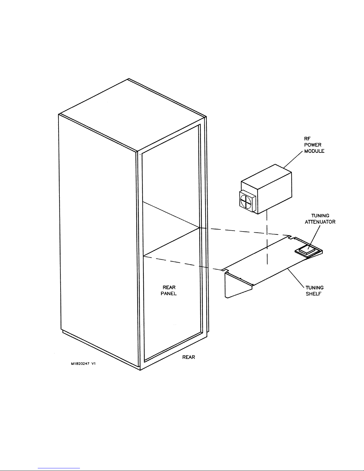
10 000 WATT FM BROADCAST TRANSMITTER
FM10
Figure 5-2 Tuning Shelf Installation
Page 5-30
01 October 2002
Page 100

10 000 WATT FM BROADCAST TRANSMITTER
FM10
Table 5- Factory Determined Measurements for Critical Parameters
SER # _________ CARRIER FREQ (ƒc) __________MHz ASSIGNED FWD PWR __________WATTS
RF DRIVE RELATED MEASUREMENTS
IPA MODULE INPUT (A17J5) __________W RF DRIVE LEVEL (A14TP7)
_______VDC (RF OFF)
_______VDC (PA VDC at 20V)
_______VDC (______ Fwd Pwr)
INTERMEDIATE RF RELATED MEASUREMENTS
PA VDC PA VDC SET FOR
SET FOR MINIMUM ASSIGNED FWD PWR
IPA FWD PWR LEVEL (A14TP5) __________ VDC __________ VDC
IPA REFLD PWR LEVEL (A14U33-7) __________ VDC __________ VDC
IPA VDC __________ VDC __________ VDC
IPA CONTROL LEVEL (A5A1TP9) __________ VDC __________ VDC
A5A1TP11 __________ VDC __________ VDC
IPA PDM CONTROL LEVEL (A5A1TP16) __________ VDC __________ VDC
RF POWER RELATED MEASUREMENTS
PRELIM FWD PWR FWD PWR SET TO
(PA VDC SET TO 20 VDC) ASSIGNED LEVEL
B+ VDC __________ VDC __________ VDC
PA VDC 20.0 VDC __________ VDC
PA VOLTS COMMON (A5A1TP6) __________ VDC __________ VDC
PA CONTROL LEVEL (A5A1TP7) __________ VDC __________ VDC
A5A1TP12 __________ VDC __________ VDC
PA PDM CONTROL A/C/E (A5A1TP14) __________ VDC __________ VDC
PA PDM CONTROL B/D/F (A5A1TP15) __________ VDC __________ VDC
FORWARD POWER __________ WATTS __________ WATTS
TOTAL CURRENT __________ AMPS __________ AMPS
Page 5-31
01 October 2002
 Loading...