


ATU-HP
Automatic
Antenna Tuning
Unit
Technical Instruction Manual
Issue 2.0 .........................06 October 2011
Nautel Limited
10089 Peggy's Cove Road,
Hackett's Cove, NS, Canada B3Z 3J4
T.+1.902.823.2233 F.+1.902.823.3183
info@nautel.com
U.S. customers please contact:
Nautel Inc.
201 Target Industrial Circle, Bangor ME 04401
T.+1.207.947.8200 F.+1.207.947.3693
info@nautel.com
e-mail: support@nautel.com
www.nautel.com
© Copyright 2011 NAUTEL. All rights reserved.


Warranty
by Nautel Limited/Nautel Inc. (herein after referred to as Nautel)
Nautel Limited/Nautel Incorporated, hereinafter referred to as Nautel, guarantees all mechanical and electrica l par ts of
the equipment for a period of thirteen months from date of shipment.
1. A "Part Failure" shall be deemed to have occurred when the part has become defective, or does not have the
characteristics required for the specified equipment performance:
(a) When the equipment is operated within the design parameters, and
(b) When the equipment is installed and adjusted according to Nautel's prescribed procedures as stated in
2. Nautel shall provide replacements for all "Parts" at no cost to the Customer when they become defective during
3. In the event that a "Part" fails during the warranty period and causes damage to a sub-assembly that cannot be
4. Where warranty replacements or repair are provided under items 2 or 3, Nautel will pay that part of the shipping
5. Warranty replacement parts and repair, which are provided under items 2 or 3, shall be guaranteed for a period
6. Nautel will not assume responsibility fo r any ch ar ges incurr ed by ot her t han Na ute l employ ee s.
7. Nautel shall have the privilege of investigating whether failures have been caused by factors beyond its control.
8. Nautel shall in no event be liable for any consequential damages arising from the use of this equipment.
9. When requesting a warranty repair/replacement, please provide complete and accurate information. Observe
10. When ordering spare/replacement parts, please provide complete and accurate information. Refer to the parts
the instruction manual.
the warranty period, and upo n the ret urn of the de fect ive par t.
readily repaired in the field, the entire sub-assembly so damaged may be returned to Nautel for repair. The
repairs will be made without charge to the Customer.
costs incurred in returning the part/assembly t o t he C u sto mer .
of ninety days from date of shipment or until the end of the original warranty period, whichever occurs later.
the instructions regarding 'Equipment Being Returned to Nautel' on page two of this warranty and provide the
information requested.
list of the Repair manual for ordering info rmat ion. Provid e as mu ch of the inf orma tio n requ este d for 'E quip ment
Being Returned to Nautel' on page two of this warranty as is practical. The information identified by an asterisk
is the minimum required.
Nautel Limited Nautel Inc.
10089 Peggy's Cove Road 201 Target Industrial Circle
Hackett's Cove NS Canada B3Z 3J4 Bangor ME USA 04401
T. 1.902.823.2233 F. 1.902.823.3183 T. 1.207.947.8200 F. 1.207.947.3693
24hr. Answering Service 1.902.823.3900
Customer Service Notice
A ‘Technical Assistance’ and ‘Plug-in Module Exchange’ service is available to Nautel users.
ATU-HP Technical Instruction Manual Oct.06.11

Factory Support
TECHNICAL ASSISTANCE
Nautel's field service department provides telephone technical assistance on a 24 hour, seven days a week basis.
Requests by other media (facsimile or e-mail) will be responded to the next working day if rece ived after Nautel's normal
working hours. Contact the appropriate field service centre from the following:
U.S.A. customers use: Nautel Incorporated Telephone 207-947-8200 (24 hours)
201 Target Industrial Circle Facsimile 207-947-3693
Bangor, Maine 04401
All other customers use: Nautel Limited Telephone 902-823-3900 (24 hours)
10089 Peggy’s Cove Road, Facsimile 902-823-3183
Hackett’s Cove, NS, Canada E-Mail support@nautel.com
B3Z 3J4 Web www.nautel.com
MODULE EXCHANGE SERVICE
In order to provide Nautel customers with a fast and efficient service in the event of a problem, Nautel operates a
factory rebuilt, module exchange service which takes full advantage of the high degree of module redundancy in
Nautel equipment. This module exchange service is operated from Nautel’s factory in Bangor, Maine and Hackett’s
Cove, Nova Scotia. These two locations allow us to provide a quick turn around service to keep our customers on
the air. During the transmitter’s warranty period, up to thirteen months from shipment, repair and exchange of
modules is at no charge to the customer. When the warranty has expired, a charge of 80% of the list price for all
exchanged modules is made. If the faulty module is returned to Nautel within 30 days, a credit is issued reducing
this charge by one half to 40% of the list price. U.S.A. customers are required to contact our Bangor, Maine facility.
Canadian and overseas customers should contact our Nova Scotia, Canada facility.
EQUIPMENT BEING RETURNED TO NAUTEL
All equipment being returned to Nautel and all requests for repairs or replacements should be marked 'field return' and
addressed to the appropriate Nautel facility.
Complete and accurate information regarding the equipment being returned will ensure prompt attention and will
expedite the dispatch of replacements. Refer to the nameplate on the transmitter and/or the appropriate
module/assembly to obtain name, type, part and serial number information. Refer to the parts list of this manual or the
appropriate service instruction manual for additional ordering information.
The following information should accompany each request:
* Model of Equipment
* Serial number of Equipment
* Name of Part/Assembly
Serial number of Part/Assembly
* Complete reference designation of Part/ Asse mbly
* Nautel's part number of Part/ Assemb ly
* OEM's part number of Part/Assembly
Number of hours in Use
Nature of defect
* Return shipping address
* Denotes minimum information required to order spare/replacement parts
ATU-HP Technical Instruction Manual Oct.06.11

Safety
Symbols
General definitions of safety symbols used on equipment or in manuals.
DANGER – HIGH VOLTAGE
Indicates dangerous voltages (in excess of 72 V), capable of causi ng a fatal
electrical shock, are present on or near parts bearing this label.
GROUND (EARTH)
Used with wiring terminals to indicate the terminal must be connected to
earth ground before operating equipment. If power is supplied without
grounding the equipment, there is a risk of receiving a severe or fatal
electrical shock. Also used on electrical schematics to indicate a part that is
connected to earth ground.
GROUND (PROTECTIVE or SAFETY)
Used with protective (safety) conductor terminals to indicate the terminal
must be connected to ground before operating the equipment. If power is
supplied without grounding the equipment, there is a risk of receiving a
severe or fatal electrical shock.
ELECTROSTATIC SENSITIVE
Indicates a part or assembly is or contains devices that are electrostatic
sensitive. To prevent damage to these devices, ensure the handling
procedures outlined in this manual are observed.
WARNING
CAUTION
NOTE
A WARNING denotes a hazard. It identifies an operating procedure,
condition, etc. which, if not strictly observed or adhered to, could result in
injury or death to personnel. Throughout the technical manual, a
WARNING shall immediately precede the text to which it applies.
A CAUTION denotes a hazard. It identifies an operating procedure,
condition, etc., which, if not strictly observed or adhered to, could result in
damage to, or destruction of the equipment. Throughout the technical
manual, a CAUTION shall immediately precede the text to which it
applies.
A NOTE denotes important information pertaining to an operating
procedure, condition, statement, etc., which is essential to highlight. A
NOTE may precede or follow the text to which it applies.
ATU-HP Technical Instruction Manual Oct.06.11

Safety
Toxic Hazard Warning
There are devices used in this equipment containing beryllium oxide ceramic,
which is non-hazardous during normal device operation and under normal device
failure conditions. These devices are specifically identified in the equipment
parts list(s).
DO NOT
HAZARDOUS IF INHALED. Unserviceable devices should be disposed of as
harmful waste.
cut, crush or grind devices because the resulting dust may be
ATU-HP Technical Instruction Manual Oct.06.11

Contents Page
1 GENERAL INFORMATION
1.1 INTRODUCTION 1-1
1.2 FACTORY SUPPORT 1-1
1.3 PURPOSE AND SCOPE OF MANUAL 1-1
1.4 PURPOSE OF EQUIPMENT 1-1
1.5 MECHANICAL DESCRIPTION 1-1
1.6 TECHNICAL SUMMARY 1-2
1.7 TEST EQUIPMENT AND SPECIAL TOOLS 1-2
2 PREPARATION FOR USE AND INSTALLATION
2.1 INTRODUCTION 2-1
2.2 PREPARATION FOR USE 2-1
2.2.1 Mounting Considerations 2-1
2.2.2 Environmental Considerations 2-1
2.2.3 Proximity to Transmitter 2-1
2.2.4 Antenna Structure 2-1
2.2.5 Customer Required Interfacing 2-5
2.2.5.1 RF Output Feed Cable 2-5
2.2.5.2 Remote Control/Monitor Wiring 2-5
2.2.5.3 RF Input Cable 2-5
2.2.5.4 Ac Power Cable 2-5
2.2.5.5 Ground Connection 2-5
2.2.6 Pre-Startup User Determined Information 2-6
2.2.6.1 Carrier Frequency 2-6
2.2.6.2 Antenna Capacitance 2-6
2.2.7 Parts Supplied by Nautel 2-7
2.2.8 Test Equipment 2-7
2.2.9 Available Options 2-7
2.2.9.1 Solar Shield 2-7
2.2.9.2 Frequency Agile Capacitor Kit 2-7
2.2.9.3 Series Resistor 2-7
2.3 UNPACKING 2-7
2.4 INSTALLATION 2-10
2.5 SYSTEM TURN-ON/TUNING PROCEDURE 2-10
2.5.1 Adjusting the Spark Gap 2-26
2.6 INCREASING ANTENNA BANDWIDTH 2-28
3 OPERATING INSTRUCTIONS
3.1 INTRODUCTION 3-1
3.2 EMERGENCY SHUTDOWN 3-1
3.3 CONTROLS AND INDICATORS 3-1
ATU-HP Technical Instruction Manual Oct.06.11

Contents Page
4 TESTING AND ADJUSTMENT
4.1 INTRODUCTION 4-1
4.2 OPERATING PRECAUTIONS 4-1
4.3 FUNCTIONAL TESTS 4-1
4.3.1 General 4-1
4.3.2 Initial Settings 4-1
4.3.3 Manual Check of Tuning Drive 4-2
4.3.3.1 Inductive Tuning Motor 4-2
4.3.3.2 Resistive Tuning Motor 4-2
4.3.4 Initial Check of RF Tuning and
Automatic Operation 4-3
4.3.5 Final Tuning of RF Circuits 4-4
4.4 NON-STANDARD ADJUSTMENTS 4-5
4.4.1 Antenna Current Meter Calibration 4-5
5 MAINTENANCE AND TROUBLESHOOTING
5.1 GENERAL 5-1
5.2 SCHEDULED MAINTENANCE 5-1
5.2.1 Cleaning the ATU-HP 5-1
5.2.2 Checking Hardware 5-1
5.3 CORRECTIVE MAINTENANCE 5-1
5.3.1 Replacing a Failed Fan 5-2
5.3.2 Checking/Replacing the Inductive
Tuning Motor 5-2
5.3.3 Checking/Replacing the Resistive
Tuning Motor 5-3
6 THEORY OF OPERATION
6.1 INTRODUCTION 6-1
6.2 ANTENNA TUNING UNIT OVERVIEW 6-1
6.2.1 ATU Control PWB 6-1
6.2.1.1 Power Supplies 6-1
6.2.1.2 Servo Probe 6-1
6.2.1.3 Forward/Reflected Power Probe 6-1
6.2.1.4 Input Voltage and Current Probes 6-1
6.2.1.5 Microcontroller 6-2
6.2.1.6 Antenna Current Probe 6-2
6.2.2 Matching Transformer/Current Probe 6-2
6.2.4 Tuning Coils 6-2
6.2.3 Resistive Matcher/Capacitor PWB 6-2
ATU-HP Technical Instruction Manual Oct.06.11

Contents Page
6.2.5 Tuning Drive Motor 6-2
6.3 DETAILED CIRCUIT DESCRIPTIONS 6-5
6.3.1 Servo Probe 6-5
6.3.2 Forward/Reflected Power Probe 6-5
6.3.3 Power Supplies 6-5
6.3.4 Current/Voltage Samples 6-6
6.3.5 Antenna Current Probe 6-6
6.3.6 Microcontroller Control 6-6
6.3.6.1 Analog Inputs 6-6
6.3.6.2 Digital Inputs 6-7
6.3.6.3 Digital Outputs 6-8
6.3.7 Serial Communications (RS485) 6-9
6.3.8 Motor Limit Control 6-9
7 PARTS INFORMATION
7.1 INTRODUCTION 7-1
7.2 REFERENCE DESIGNATIONS LISTS 7-1
7.3 COLUMN CONTENT EXPLANATION 7-1
7.3.1 Ref Des Column 7-1
7.3.2 Description Column 7-1
7.3.3 Nautel # Column 7-1
7.3.4 Vendor # Column 7-1
7.3.5 OEM Code Column 7-2
7.4 OEM CODE TO MANUFACTURER
CROSS-REFERENCE 7-2
7.4.1 Manufacturer’s Index 7-2
7.5 COMMON ABBREVIATIONS/ACRONYMS 7-2
8 WIRING INFORMATION
8.1 INTRODUCTION 8-1
8.2 WIRING LISTS NOT PROVIDED 8-1
8.3 PRINTED WIRING PATTERNS 8-1
8.4 WIRE COLORS 8-1
8.5 WIRING LISTS PROVIDED 8-1
9 ELECTRICAL SCHEMATICS
9.1 INTRODUCTION 9-1
9.2 COMPONENT VALUES 9-1
9.3 GRAPHIC SYMBOLS 9-1
9.4 LOGIC SYMBOLS 9-1
ATU-HP Technical Instruction Manual Oct.06.11

Contents Page
9.5 REFERENCE DESIGNATIONS 9-1
9.6 UNIQUE SYMBOLOGY 9-1
9.6.1 Type of Inputs/Outputs 9-1
9.6.2 Logic Level/Convention 9-1
9.7 IDENTIFICATION OF SCHEMATIC
DIAGRAMS 9-1
9.8 STRUCTURE OF SCHEMATICS 9-2
9.9 LOCATING THE SCHEMATIC DIAGRAM(S)
FOR A FUNCTIONAL BLOCK 9-2
9.10 LOCATING A PART/ASSEMBLY IDENTIFIED
ON A SCHEMATIC 9-2
10 MECHANICAL DRAWINGS
10.1 INTRODUCTION 10-1
10.2 LOCATING ASSEMBLY DETAIL DRAWINGS 10-1
10.3 CONTENT OF MECHANICAL DRAWINGS 10-1
List of Tables
1-1 Recommended Site Test Equipment and Special Tools 1-3
2-1a Frequency Dependent Capacitors for DGPS Applications 2-8
2-1b Frequency Dependent Capacitors for Low Power NDB Applications 2-8
2-1c Frequency Dependent Capacitors for High Power NDB Applications 2-9
2-1d Capacitors Ordering Information 2-9
2-2 Tuning Coil Inductance Values (μH) 2-11
2-3 T1 Matching Transformer 50 Ohm Connections 2-16
2-4 Determining ‘R Match’ 2-17
2-5 T1 Taps vs Resistance Ratio 2-17
2-6a Loading Coil (DGPS) Series Connection (500-136 μH) 2-20
2-6b Loading Coil (DGPS) Parallel Connection (135-20 μH) 2-21
2-6c Loading Coil (NDB Low Power) Series Connection (2700-640 μH) 2-22
2-6d Loading Coil (NDB Low Power) Parallel Connection (639-50 μH) 2-23
2-6e Loading Coil (NDB High Power) Series Connection (1200-300 μH) 2-24
2-6f Loading Coil (NDB High Power) Parallel Connection (299-25 μH) 2-25
2-7 T2 Taps vs Series Resistance 2-31
3-1 ATU Control/Monitor PWB Controls and Indicators 3-3
7-1 Manufacturer’s Index 7-3
8-1 Wiring Lists Provided 8-1
8-2 Wiring List – ATU-HP – Automatic Antenna Tuning Unit 8-2
9-1 Electrical Schematics 9-2
10-1 Mechanical Drawings 10-1
ATU-HP Technical Instruction Manual Oct.06.11

Contents Page
List of Figures/Drawings
1-1 ATU-HP Automatic Antenna Tuning Unit 1-2
2-1 Typical Site Layout 2-2
2-2 Examples of Typical Installations (Sheet 1 of 2) 2-3
2-2 Examples of Typical Installations (Sheet 2 of 2) 2-4
2-3 ATU-HP – Customer Interface Connections 2-6
2-4 Initial RF Wiring Connections 2-12
2-5 ATU Control/Monitor PWB – Pushbutton Switches and LEDs 2-12
2-6 Flow Diagram – Loading Coil Tuning 2-13
2-7 Post-Inductive Tuning RF Wiring Connections 2-14
2-8 Flow Diagram – Determining Antenna Resistance 2-15
2-9 Post-Resistive Tuning RF Wiring Connections 2-16
2-10 Variometer Positioning within Loading Coil L1A 2-18
2-11 Variable Matching Transformer 2-19
2-12a Loading Coil (DGPS) Series Connection (500-136 μH) 2-12
2-12b Loading Coil (DGPS) Parallel Connection (135-20 μH) 2-13
2-12c Loading Coil (NDB Low Power) Series Connection (2700-640 μH) 2-14
2-12d Loading Coil (NDB Low Power) Parallel Connection (639-50 μH) 2-15
2-12e Loading Coil (NDB High Power) Series Connection (1200-300 μH) 2-16
2-12f Loading Coil (NDB High Power) Parallel Connection (639-20 μH) 2-17
2-13 Peak Antenna Voltage Versus Spark Gap Setting 2-26
2-14a Flow Diagram – Adding Antenna Series Resistance (DGPS) 2-29
2-14b Flow Diagram – Adding Antenna Series Resistance (NDB) 2-30
2-15 Partial View of Series Resistance Transformer T2 Taps 2-31
2-16 ATU-HP – Dimensional Information and Mounting Options 2-32
3-1 Part of ATU Control/Monitor PWB A1 (NAPC144
6-1 Block Diagram of ATU-HP Automatic Antenna Tuning Unit 6-3
SD-1 Electrical Schematic – ATU-HP Automatic Antenna Tuning Unit
(NAT40
SD-2 Electrical Schematic – ATU Control/Monitor PWB (NAPC144
(Sheet 1 of 2) SD-2
SD-3 Electrical Schematic – ATU Control/Monitor PWB (NAPC144
(Sheet 2 of 2) SD-3
MD-1 Assembly Detail –ATU-HP Automatic Antenna Tuni ng Unit
(NAT40
MD-2 Assembly Detail – ATU Control/Monitor PWB (NAPC144
A) SD-1
A) MD-1
A/01) 3-2
A/01)
A/01)
A/01) MD-2
ATU-HP Technical Instruction Manual Oct.06.11


Release Control Record
Issue Date Reason
2.0 06 October 2011 Release 2 of product (NAT40A)
ATU-HP Technical Instruction Manual Oct.06.11


ATU-HP
TECHNICAL INSTRUCTION MANUAL
Section 1 GENERAL INFORMATION
1.1 INTRODUCTION
The ATU-HP – Automatic Antenna Tuning
Unit:
• Provides automatic tuning and
impedance matching between an
antenna and a 50 ohm feeder cable
from a DGPS (750 W – 3,000 W) or
NDB (500 W or 1000/2000 W)
transmitter.
• Automatically compensates for both
antenna system reactance changes
and resistance changes.
• Can be serially connected to its
associated transmitter, allowing a
variety of control/monitoring features,
including stabilization of the antenna
current by adjusting the associated
transmitter’s power level.
• Operates in the LF/MF band (190 kHz
to 550 kHz).
Options include a sunshield for use in
environments with high temperatures, and
a resistor assembly to allow for increased
bandwidth in high Q antenna systems.
1.2 FACTORY SUPPORT
Nautel provides after sales factory
support. Technical assistance is available
on a 24 hour, seven days a week basis. A
factory service facility for repair of
modules/assemblies is also available.
Refer to the Factory Support portion of the
Warranty pages at the front of this manual
for additional information.
1.3 PURPOSE AND SCOPE OF
MANUAL
This Technical Instruction manual
provides the information required to
install, operate and maintain the
equipment.
1.4 PURPOSE OF EQUIPMENT
The ATU-HP interfaces and impedance
matches the RF output of a transmitter to
an antenna. Two servomechanisms
automatically maintain a well matched
condition when either the antenna
reactance or resistance changes. Through
a serial interface, the transmitter’s output
power can be controlled to provide
antenna current stability. Remote control
facilities are incorporated to allow
unattended operation from a remote
location.
1.5 MECHANICAL DESCRIPTION
The ATU-HP (see Figure 1-1) is housed in
an all-weather cabinet suitable for outdoor
installation close to the antenna. Electrical
interconnection is made via cables that
enter the cabinet through sealed
connectors located on the side. The ac
input wiring is terminated on terminal
blocks located on the ATU control/monitor
PWB (A1), which is located behind the
cabinet’s front cover. The remote wiring
terminates on either terminal blocks or a
9-pin D-sub connector also located on A1.
The cabinet is assembled from heavy
gauge aluminium alloy and is fitted for
rear or base mounting. There is a
weather–tight, removable cover on the
front of the cabinet, which permits access
to the ATU-HP. It is removed by
unfastening the three pull-down latches on
each side of the cabinet. The cabinet
ATU-HP Technical Instruction Manual Page 1-1
Section 1 General Information Issue 2.0

contains a loading coil assembly, lightning
arrestor spark gap, insulated RF feedthrough connector, a variable matching
transformer assembly, temperature
sensor, two cooling fans, a PWB/chassis
that contains the electronic circuitry and a
matching transformer and tuning
capacitors. The electrical wiring access
holes are fitted with liquid tight connectors
which can be tightened to ensure rodents,
dirt and moisture do not enter the cabinet.
1.6 TECHNICAL SUMMARY
An equipment brochure, containing a
technical summary, is provided with this
manual.
1.7 TEST EQUIPMENT AND
SPECIAL TOOLS
Table 1-1 lists the test equipment and
special tools that are required to operate
and maintain the ATU-HP.
Figure 1-1 – ATU-HP- Automatic Antenna Tuning Unit
Page 1-2 ATU-HP Technical Instruction Manual
Issue 2.0 Section 1 General Information

Table 1-1: Recommended Site Test Equipment and Special Tools
NOMENCLATURE
Dummy Load 50 ohms, rated for twice rated
Digital Multimeter
Ac Voltmeter HP400E Testing and
Oscilloscope Tektronix Model T922 Testing and
Current Probe Nautel Part # 195-9131
Standard Electronic Tool
Kit
Standard Wrenches 1/4 inch and 1/2 inch sizes Spark gap
Hex-Head Allen Key M3 size Tuning motor
Handheld Calculator Various Calculating
PART/MODEL NUMBER OR TYPE
(EQUIVALENTS MAY BE USED)
transmitter power
3 1/2 digit, ac and dc volts (10 MΩ
input), ohms and amps, ±0.5% accuracy,
Beckman 3010
Contact Nautel if required
Various size screwdrivers and nut-
drivers
APPLICATION
'Off-air' testing
Testing and
maintenance
maintenance
maintenance
Antenna Current
Meter Calibration
Miscellaneous
maintenance
adjustment and RF
feed cable
connection.
maintenance or
replacement.
resistance ratios
ATU-HP Technical Instruction Manual Page 1-3
Section 1 General Information Issue 2.0


ATU-HP
TECHNICAL INSTRUCTION MANUAL
Section 2 PREPARATION FOR USE AND INSTALLATION
2.1 INTRODUCTION
This section contains pre-installation and
installation information required in
unpacking, installing and preparing the
ATU-HP antenna tuning unit for use.
NOTE
Failure to comply with these
recommendations and instructions could
void the manufacturer’s warranty. Please
review Nautel’s warranty terms for more
information.
2.2 PREPARATION FOR USE
Sites should be prepared to receive the
ATU prior to its delivery and/or installation.
The following must be taken into
consideration when preparing new sites
and should be used as the evaluating
criteria at existing sites. Nautel
recommends that all requirements be
incorporated to ensure optimum reliability
and performance.
2.2.1 Mounting Considerations
The ATU should be installed as close to
the vertical (radiating) section of the
antenna as is practical. It may be rear
mounted on a grounded part of an antenna
structure or a wall or base mounted. Refer
to Figure 2-16 for external and mounting
dimensions for both mounting options. The
base of the ATU must be located at a
higher elevation than any possible snow
accumulation, to allow maintenance and to
prevent the possibility of water
accumulation.
Nautel ships the ATU-HP with brackets
installed for rear mounting.
2.2.2 Environmental
Considerations
Refer to Figure 2-16 for environmental
considerations for the ATU, such as
operating temperature, altitude and weight.
2.2.3 Proximity to Transmitter
The practice of locating the ATU and
transmitter within a single building beneath
the antenna is not recommended. It is
extremely difficult to provide adequate
shielding to prevent feedback between the
high RF field of the antenna and the low
signal level circuits of the transmitter.
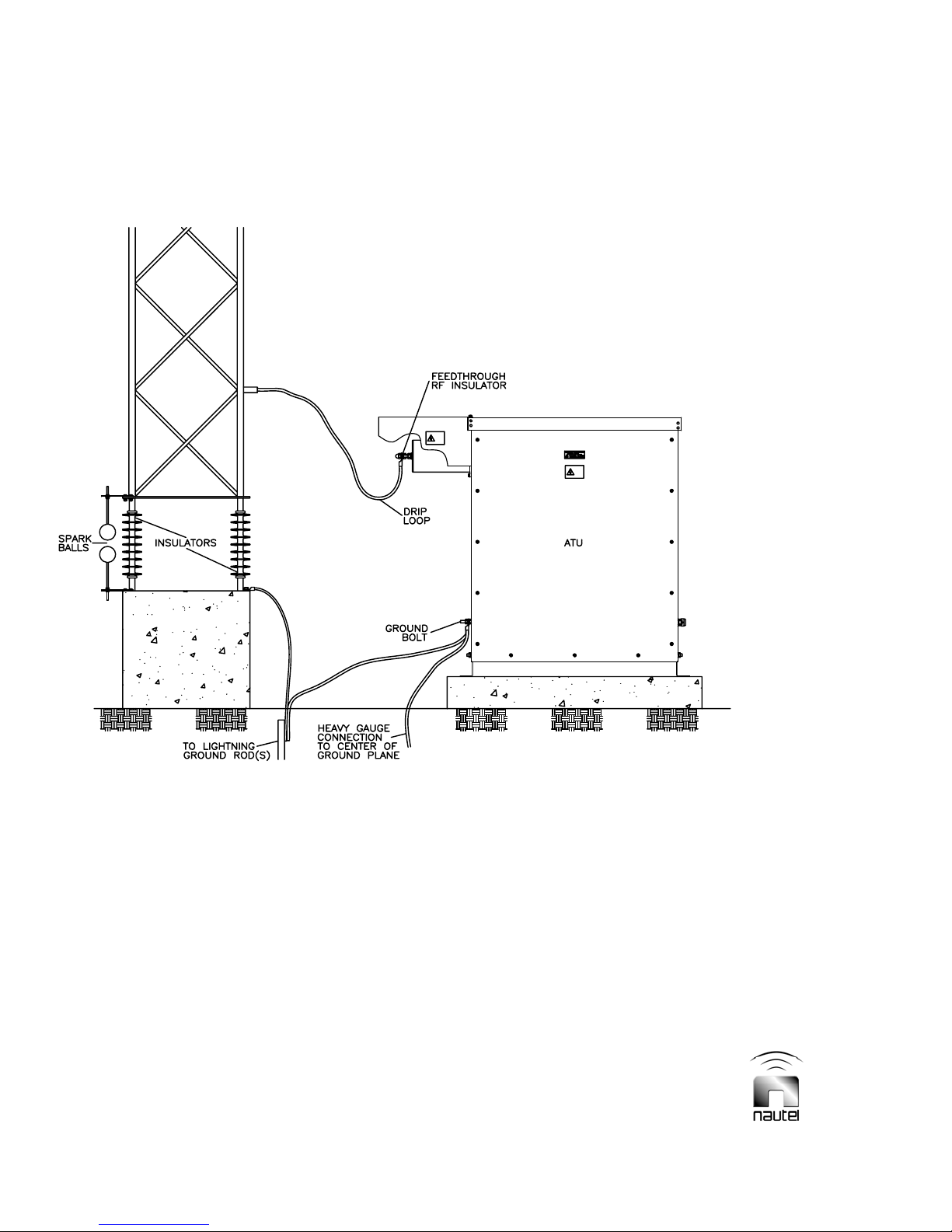
2.2.4 Antenna Structure
The ground plane should be arranged
symmetrically around the antenna's vertical
(radiating) section. Refer to Figure 2-1 for a
typical site layout. Refer to Figure 2-2 for
various interconnection scenarios between
the antenna and ATU. In the case of Figure
2-2 (a), a down lead insulator is shown
which is used to keep the downlead under
tension. This insulator is necessary to
minimize movement of the downlead and
to relieve any mechanical strain from the
ATU feed-through insulator. The downlead
should be positioned at least two feet away
from the ATU or any other grounded metal
structure to minimize antenna capacitance
change due to wind induced movement of
the downlead.
NOTE
ATU-HP Technical Instruction Manual Page 2-1
Section 2 Preparation for Use and Installation Issue 2.0

Figure 2-1 – Typical Site Lay out
Page 2-2 ATU-HP Technical Instruction Manual
Issue 2.0 Section 2 Preparation for Use and Installation

Figure 2-2 – Examples of Typical Installations (Sheet 1 of 2)
(a)
T Antenna
ATU-HP Technical Instruction Manual Page 2-3
Section 2 Preparation for Use and Installation Issue 2.0
(b)
Vertical
Tower
Antenna
Figure 2-2 – Examples of Typical Installations (Sheet 2 of 2)
Page 2-4 ATU-HP Technical Instruction Manual
Issue 2.0 Section 2 Preparation for Use and Installation

2.2.5 Customer Required
Interfacing
The following paragraphs describe the
connections that must be made to the ATU
by the customer. For ease of installation, it
is recommended that wiring and applicable
connectors are on site prior to unpacking/
installing the ATU. Figure 2-3 illustrates the
ATU-HP’s interface.
2.2.5.1 RF Output Feed Cable
The method by which the ATU output (J2)
connects to the antenna is critical because
of the high voltage, current and impedance
levels at this interface. The antenna feed
RF cable connects to the feed-through/
insulator located at the top left of the ATU
cabinet. This cable must be of adequate
diameter to avoid corona discharge, must
not contain sharp bends and should have
sufficient length to permit a drip loop at the
feed-through/insulator. Refer to Figure 2-2
(a) or (b) for a typical downlead connection.
2.2.5.2 Remote Control/Monitor Wiring
The ATU-HP can interface with a Nautel
Vector series DGPS or NDB transmitter
using RS-485 serial communication.
Connections are made via a cable that
passes through a liquid-tight connector in
the side of the cabinet, to the ATU control/
monitor PWB (9-pin D connector J3 or
2.2.5.3 RF Input Cable
A suitably rated, good quality, 50 Ω RF
coaxial cable should be used to
interconnect the ATU-HP and the
transmitter. The RF input connection is
made to N connector J3 at the side of the
ATU-HP cabinet. Where practical, it is
recommended that the cabling between the
transmitter and ATU-HP be installed
underground (i.e., suitable for direct earth
burial). The only penalty for long distances
between the ATU-HP and the transmitter is
the cost of the cable and the power loss in
the coaxial feeder cable. This loss is
typically 0.1 dB/100 m for a good quality,
1/2-inch diameter cable.
2.2.5.4 AC Power Cable
The ac power connection is made via a
cable that passes through one of the liquidtight connectors on the side of the ATU-HP
cabinet to TB2 of ATU control/monitor
PWB A1 (see ac power options in Figure
2-3). The ac power cable should conform
to local electrical codes. The ac power for
the ATU-HP should be provided on a
dedicated circuit from the service
entrance. Facilities to disconnect this
service should be provided. Ac power
requirements for obstruction lighting, etc.,
should be individually supplied by branch
circuits from the service entrance panel.
terminals TB3-6 though TB3-10). The cable
should be shielded and suitable for direct
earth burial, to be installed underground
between the transmitter and ATU-HP. The
RS-485 specification limits the cable length
to a maximum of 4000 ft. (1220 m).
The following pin-out and terminal
assignment applies:
+5V A1J3-1 or A1TB3-6
Ground A1J3-2 or A1TB3-7
TX/RX A1J3-3 or A1TB3-8
The ATU-HP is configured to operate from
one of three ac power sources:
115 V ac, single-phase, 0.25 A max.
230 V ac, single-phase, 0.15 A max.
230 V ac, split-phase, 0.15 A max.
2.2.5.5 Ground Connection
A ground cable (6 AWG minimum) must be
connected between the centre of the
antenna ground plane and the ground lug
located on the bottom, left-hand side of the
ATU-HP cabinet. This ground cable should
TX/RX A1J3-4 or A1TB3-9
DE/RE A1J3-5 or A1TB3-10
be continuous and low resistance to ensure
efficient operation.
NOTE
ATU-HP Technical Instruction Manual Page 2-5
Section 2 Preparation for Use and Installation Issue 2.0

AC INPUT CONFIGURATION, CUSTOMER CONNECTION
Figure 2-3 – ATU-HP Automatic Tuning Unit – Customer Interface Connections
The ground lug should also connect to
ground rod(s) that provide a low
impedance path to ground for lightning
protection.
2.2.6 Pre-Startup User
Determined Information
The following user determined information
will minimize the start-up time of the ATUHP. It should be determined and recorded
prior to equipment installation.
2.2.6.1 Carrier Frequency
Determine/record the carrier frequency
assigned to the associated transmitter.
2.2.6.2 Antenna Capacitance
Determine/record the approximate antenna
capacitance from antenna design records
or by measurement. A Nautel technical
paper entitled ‘NDB Antennas’ may be
used to estimate antenna capacitance.
Page 2-6 ATU-HP Technical Instruction Manual
Issue 2.0 Section 2 Preparation for Use and Installation

2.2.7 Parts Supplied By Nautel
An ancillary parts kit is provided with each
ATU-HP. The ancillary parts are provided
to ensure the initial installation is not
delayed because of a lost or missing part.
They are not intended to be long-term
maintenance spares. An itemized listing of
the ancillary parts kit is included in its
packing list.
2.2.8 Test Equipment
The test equipment and special tools
required to install and maintain the
ATU-HP are listed in Table 1-1.
2.2.9 Available Options
There are several options available for the
ATU-HP automatic antenna tuning unit.
Each option is described below to assist
the user in selecting the final configuration
for the system.
2.2.9.1 Solar Shield
A solar shield (Nautel Part # 195-9090,
shown in Figure 2-16) is available to
assist in reducing the temperature of the
ATU-HP due to solar radiation. If
purchased, the solar shield will be factory
installed.
2.2.9.2 Frequency Agile Capacitor Kit
A capacitor kit (Nautel Part # 195-9094 or
-01 through -03) is available to allow
frequency agility. In addition to frequency
dependency, the capacitor values and
quantities are also dependent on the
tuning coils installed in the ATU, which are
determined by the associated transmitter.
Refer to either Table 2-1a for DGPS
applications, Table 2-1b for low power
(500 W) NDB applications or Table 2-1c
for high power (1,000/2,000 W) NDB
applications to determine the particular
values and quantities used for a given
operating frequency. Refer to Table 2-1d
to cross-reference the capacitor value to
the Nautel part number for ordering
purposes.
2.2.9.3 Series Resistor Kit
An external series resistor kit (Nautel Part
# 195-9054) is available to assist in
improving the bandwidth of the ATU-HP.
The resistance is adjustable via tap
settings on a matching transformer, also
provided. The external series resistor is
factory installed on a solar shield (see
paragraph 2.2.9.1), which is included with
this kit.
2.3 UNPACKING
The ATU-HP is packed in a wooden crate,
fully assembled. A packing list, on the
outside of the crate, provides a detailed
listing of crate contents. All shipments
should be inspected for transit damage
prior to acceptance. Open the crate and
remove the contents as follows:
CAUTION
The ATU-HP (without solar shield option)
weighs 111 pounds. At least two people, or
sufficient mechanical assistance, should be
available to unpack the ATU-HP.
(a) Position the crate in a clear area that
will permit extraction of the ATU-HP
without risk of damage to the unit or
injury to personnel.
(b) Stand the crate upright as marked on
the side of the crate.
(c) Remove the crate panel identified as
the front using a screwdriver (battery
powered is recommended).
(d) Remove any small packages, as
identified in the packing list, that are
located between the ATU-HP cabinet
and the packing crate.
(e) Extract the ATU-HP from the crate.
ATU-HP Technical Instruction Manual Page 2-7
Section 2 Preparation for Use and Installation Issue 2.0

Table 2-1a: Frequency Dependent Capacitors for DGPS Applications
(from Nautel Part # 195-9094 capacitor kit)
FREQ
(kHz)
280 4 - - - 317 3 - - 1
285 3 1 1 1 324 3 - - -
290 3 1 1 - 440 1 1 - 1
295 3 1 - 1 458 1 1 - -
300 3 1 - - 47 8 1 - 1 1
305 3 - 1 1 502 1 - 1 -
310 3 - 1 - 529 1 - - 1
Capacitors (pF) and qty Capacitors (pF) and qty
1750 875 430 218
FREQ
(kHz)
1750 875 430 218
Table 2-1b: Frequency Dependent Capacitors for Low Power NDB Applications
(from Nautel Part # 195-9094-02 capacitor kit)
FREQ
(kHz)
200 1 1 1 1 1 1 268 1 1 1
202 1 1 1 1 1 272 1 1
203 1 1 1 1 1 276 1 1
205 1 1 1 1 280 1
207 1 1 1 1 1 285 1 1 1 1 1
208 1 1 1 1 290 1 1 1 1
210 1 1 1 1 295 1 1 1 1
212 1 1 1 300 1 1 1
214 1 1 1 1 1 305 1 1 1 1
216 1 1 1 1 311 1 1 1
218 1 1 1 1 317 1 1 1
220 1 1 1 324 1 1
222 1 1 1 1 331 2 1 1 1
224 1 1 1 338 2 1 1
227 1 1 1 346 2 1 1
229 1 1 355 2 1
231 1 1 1 1 1 364 2 1 1
224 1 1 1 1 374 2 1
236 1 1 1 1 385 2 1
239 1 1 1 397 2
242 1 1 1 1 410 1 1 1 1
245 1 1 1 424 1 1 1
248 1 1 1 440 1 1 1
251 1 1 458 1 1
254 1 1 1 1 478 1 1 1
257 1 1 1 502 1 1
261 1 1 1 530 1 1
264 1 1
7000 3500 1750 875 430 218
Capacitors (pF) and qty Capacitors (pF) and qty
FREQ
(kHz)
7000 3500 1750 875 430 218
Page 2-8 ATU-HP Technical Instruction Manual
Issue 2.0 Section 1 Preparation for Use and Installation

Table 2-1c: Frequency Dependent Capacitors for High Power NDB Applications
(from Nautel Part # 195-9094-01 capacitor kit)
FREQ
(kHz)
200 7 1 1 1 268 4 1 1
202 7 1 1 - 272 4 1 -
203 7 1 1 276 4 1
205 7 1 - 280 4 -
207 7 1 1 285 3 1 1 1
208 7 1 - 290 3 1 1 -
210 7 1 295 3 1 1
212 7 - 300 3 1 -
214 6 1 1 1 305 3 1 1
216 6 1 1 - 311 3 1 -
218 6 1 1 317 3 1
220 6 1 - 324 3 -
222 6 1 1 331 2 1 1 1
224 6 1 - 338 2 1 1 -
227 6 1 346 2 1 1
229 6 - 355 2 1 -
231 5 1 1 1 364 2 1 1
224 5 1 1 - 374 2 1 -
236 5 1 1 385 2 1
239 5 1 - 397 8
242 5 1 1 410 7 1
245 5 1 - 424 7
248 5 1 440 6 1
251 5 - 458 6
254 4 1 1 1 478 5 1
257 4 1 1 - 502 5
261 4 1 1 530 4 1
264 4 1 -
Capacitors (pF) and qty Capacitors (pF) and qty
1750 875 430 218
Table 2-1d: Capacitor Ordering Information
Capacitor Value
(pf)
109 195-9004-08
218 195-9004-06
430 195-9004-07
875 195-9004-02
1750 195-9004-03
3500 195-9004-04
7000 195-9004-05
Nautel Part #
FREQ
(kHz)
1750 875 430 218
ATU-HP Technical Instruction Manual Page 2-9
Section 2 Preparation for Use and Installation Issue 2.0

2.4 INSTALLATION
Secure the ATU-HP in its final position and
connect user interface cabling as follows:
NOTE
All electrical input connections, from
external sources, are made through cable
entrance holes in the side of the cabinet.
Refer to Figure 2-3 to locate these holes
and all other customer interface points.
(a) Mount the ATU-HP in its final position
by securing the two rear mounting
angles to a support. If base mounting
is preferred, remove the front cover to
gain full access to the mounting
angles. Using Figure 2-16 as a guide,
reinstall the angles for base mounting.
Ensure hardware is properly oriented
and tight. Do not reinstall the front
cover at this time.
(b) Ensure the transmitter is turned off.
WARNING
Extremely high, potentially lethal, RF
voltages are
present in the ATU-HP
when an RF input is being applied. Use
extreme caution near the tuning coils.
(c) If the ATU-HP is being used in
conjunction with a Nautel Vector
series transmitter, route the remote
control/monitor wiring through the
appropriate liquid-tight connector to
the ATU control/monitor PWB (A1) as
detailed in paragraph 2.2.5.2.
(d) Install the RF input cable between the
associated transmitter’s RF output
and the ATU-HP. The RF input
connector (J3) is located on the lower,
right-hand side of the cabinet. See
paragraph 2.2.5.3 for details.
(e) Connect the grounding cable from the
antenna ground plane and the lightning
ground rod(s) to the ground stud on the
lower, left-hand side of the ATU-HP
cabinet. Ensure paragraph 2.2.5.5 has
been completed.
(f) Connect the antenna RF feed cable to
the feed-through insulator (J2). Ensure
the requirements of paragraph 2.2.5.1
are met. Ensure the centre conductor
of the insulator does not rotate while
securing the RF feed cable. Verify nuts
are tight.
(g) Route the ac power cable through the
appropriate liquid-tight connector to
TB2 of the ATU control/monitor PWB
(A1). Ensure the requirements of
paragraph 2.2.5.4 are met. Refer to
Figure 2-3 to determine the specific
connections for your ac service.
(h) Install wire link(s) (minimum 18 AWG)
on appropriate terminals of TB3 (see
Figure 2-3):
• 115 V ac Link 1 to 2; Link 3 to 4
• 230 V ac Link 2 to 3
(i) Connect ATU control/monitor PWB
jumper wires A, B and C (Figure 3-1)
for the desired A1M1 meter scales:
• Forward Power
0 – 4,000 W: jumper B to E3
0 – 1,200 W: jumper B to E4
• Reflected Power
0 – 400 W: jumper A to E1
0 – 120 W: jumper A to E2
• Antenna Current
0 – 10 A: jumper C to E5
0 – 30 A: jumper C to E6
(j) Verify the proper capacitors are
installed on the capacitor bank. Refer
to Table 2-1a for DGPS applications,
Table 2-1b for low power (500 W)
NDB applications or Table 2-1c for
high power (1,000/2,000 W) NDB
applications to determine the values
and quantities used for a given
operating frequency.
Page 2-10 ATU-HP Technical Instruction Manual
Issue 2.0 Section 2 Preparation for Use and Installation

Stage 1 of Tuning Procedure
Initial Setting of L Tuning Taps (LOCAL control, TUNE SETUP on)
Table 2-2: Tuning Coil Inductance Values (μH)
ANTENNA
CAP (pF)
200
300
400
500
600
700
800
900
1000
1200
1400
1600
1800
2000
2250
2500
2750
3000
3500
190 200 250 300 350 400 450 500 550
3508 3166 2026 1407 1034 792 625 507 419
2339 2111 1351 938 689 528 417 338 279
1754 1583 1013 704 517 396 313 253 209
1403 1267 811 563 414 317 250 203 167
1169 1055 675 469 345 264 208 169 140
1002 905 579 402 295 226 179 145 120
877 792 507 352 258 198 156 127 105
780 704 450 313 230 176 139 113 93
702 633 405 281 207 158 125 101 84
585 528 338 235 172 132 104 84 70
501 452 289 201 148 113 89 72 60
439 396 253 176 129 99 78 63 52
390 352 225 156 115 88 69 56 47
351 317 203 141 103 79 63 51 42
312 281 180 125 92 70 56 45 37
281 253 162 113 83 63 50 41 33
255 230 147 102 75 58 45 37 30
234 211 135 94 69 53 42 34 28
200 181 116 80 59 45 36 29 24
2.5 INITIAL TURN-ON/TUNING
PROCEDURE
The tuning procedure is divided into three
stages:
1. Initial setting of L tuning taps
2. Determining antenna resistance
3. Final setting of L and R tuning taps
Check the top of each of the following
pages to determine the stage number and
other applicable information.
(a) Determine the approximate loading coil
inductance by entering the data
recorded for operating frequency (see.
2.2.6.1) and antenna capacitance (see.
2.2.6.2) into Table 2-2.
(b) Enter the inductance from step (a) into
the appropriate Table 2-6 (a-f), noting
the application and inductance range
for each. Determine the initial loading
coil tap settings. If the inductance was
not determined, use the shaded value
in the appropriate series connection
table (e.g., 215 μH in Table 2-6a).
FREQUENCY (kHz)
(c) Tap the loading coils L1A and L1B for
the settings determined in step (b).
See the appropriate Figure 2-12 (a-f)
for examples.
Use extreme caution near the tuning
coils. Extremely high RF voltages, that
may arc many inches of air breakdown
path
and cause severe RF burns, are
present when an RF input of any level
is applied to the ATU-HP.
Wires connecting to tuning coil taps must
be dressed in a manner that will prevent
them from coming in contact with any part
of the coils other than the tap connecting
points. Arcing that may result in damage
to the coils and/or loss of tuning may
occur.
WARNING
CAUTION
ATU-HP Technical Instruction Manual Page 2-11
Section 2 Preparation for Use and Installation Issue 2.0
Stage 1 of Tuning Procedure
Initial Setting of L Tuning Taps (LOCAL control, TUNE SETUP on)
Paragraph 2.5 continued
(d) Gain access to the ATU-HP’s control
circuitry, by removing the transparent
cover across the front of the cabinet,
noting it is secured by four screws, two
on either side of the cabinet.
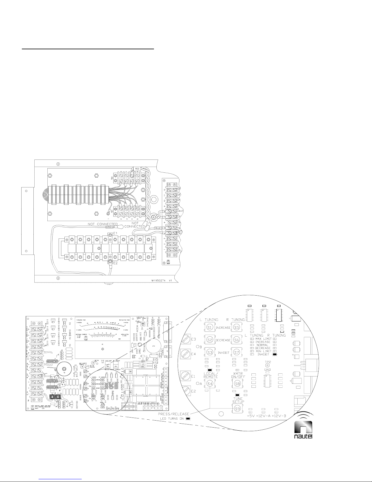
(e) Configure the RF wiring at the ATU
control/monitor PWB’s terminal block
(A1TB1) and the matching transformer
T1
terminal blocks (T1-TB1 and T1-TB2)
as shown in Figure 2-4. Disconnect
wiring from capacitor bank as
necessary.
(f) Turn on the ATU-HP’s ac power
supply. On ATU control/monitor PWB
A1, press the LOCAL/REMOTE (S4)
and TUNE SETUP (S9) so that the
LOCAL and TUNE SETUP LEDs turn
on. See Figure 2-5.
Figure 2-4 - Initial RF Wiring Connections
A1TB1
Figure 2-5 - ATU Control/Monitor PWB – Pushbutton Switches and LEDs
Page 2-12 ATU-HP Technical Instruction Manual
Issue 2.0 Section 2 Preparation for Use and Installation

Stage 1 of Tuning Procedure
Initial Setting of L Tuning Taps (LOCAL control, TUNE SETUP on)
Paragraph 2.5 continued
(g) With the ATU-HP connected to both
the transmitter and the antenna
system, turn on the transmitter (use
CW mode for NDB transmitters) and
set its output power for 100 W
(maximum).
TUNE LOADING
COILS
Turn transmitter on
Wait for L TUNING -
NORMAL, MAX
LIMIT or MIN LIMIT
LED to turn on.
(h) Using the flow diagram illustrated in
Figure 2-6, tune the ATU-HP loading
coils. Disregard the status of the R
TUNING LEDs on the ATU control/
monitor PWB during this procedure.
Turn transmitter
off. Increase
inductance to next
higher setting as
per appropriate
Table 2-6 (a–f).
L TUNING R TUNING
MAX LIMIT
INCREASE
NORMAL
DECREASE
MIN LIMIT
INHIBIT
Check L TUNING
LEDs on PWB
Which L
TUNING
LED is
on?
L TUNING R TUNING
LOADING COILS
TUNED
L TUNING R TUNING
MAX LIMIT
INCREASE
NORMAL
DECREASE
MIN LIMIT
INHIBIT
MAX LIMIT
INCREASE
NORMAL
DECREASE
MIN LIMIT
INHIBIT
Turn transmitter
off. Decrease
inductance to next
lower setting as
per appropriate
Table 2-6 (a-f).
Figure 2-6 - Flow Diagram – Loading Coil Tuning
ATU-HP Technical Instruction Manual Page 2-13
Section 2 Preparation for Use and Installation Issue 2.0

Stage 2 of Tuning Procedure
Determining Antenna Resistance (LOCAL control, TUNE SETUP on)
T1
A1TB1
Figure 2-7 – Post-Inductive Tuning RF Wiring Connections
Paragraph 2.5 continued
(i) Turn transmitter off. Configure the RF
wiring between the ATU control/
monitor PWB’s terminal block
(A1TB1) and the matching
transformer terminal blocks (T1-TB1
and T1-TB2) as shown in Figure 2-7,
noting the blue wire should be
terminated on T1-3 and the red wires
should be terminated on A1TB1-5 and
A1TB1-6.
(j) Using the flow diagram illustrated in
Figure 2-8, determine the antenna
resistance by selecting the T1 tap
settings that provide minimum reflected
power. View reflected power on the
ATU control/monitor PWB’s meter,
noting switch A1S10 must be set to
REFLD PWR and switch A1S11 must
be set to RF POWER.
Page 2-14 ATU-HP Technical Instruction Manual
Issue 2.0 Section 1 Preparation for Use and Installation
Forward power must be maintained at the
same level when determining the reflected
power. After each tapping of T1, allow the
loading coils to retune (i.e., L TUNING NORMAL LED turned on).
(k) When step (j) is complete, use Table
2-3 to determine the antenna system
resistance associated with the T1
connections that provided minimum
reflected power.
NOTE

Stage 2 of Tuning Procedure
Determining Antenna Resistance (LOCAL control, TUNE SETUP on)
Turn transmitter off.
Change taps on T1 to
next higher antenna
resistance as per
Table 2-3.
DETERMINE ANTENNA
RESISTANCE
Turn transmitter on
Wait for L
NORMAL LED to
turn on (motor
stops)
Turn transmitter off.
Change taps on T1 to
next lower antenna
resistance as per
Note reflected power level
Table 2-3
on meter
If a DECREASE
adjustment has already
been made, discontinue
loop and proceed as if
NORMAL
L TUNING R TUNING
MAX LIMIT
INCREASE
NORMAL
DECREASE
MIN LIMIT
INHIBIT
L TUNING R TUNING
Which R
TUNING
LED is on?
L TUNING R TUNING
Note reflected power level
on meter
ANTENNA RESISTANCE
DETERMINED
MAX LIMIT
INCREASE
NORMAL
DECREASE
MIN LIMIT
INHIBIT
MAX LIMIT
INCREASE
NORMAL
DECREASE
MIN LIMIT
INHIBIT
If an INCREASE,
adjustment has already
been made, discontinue
loop and proceed as if
NORMAL
Figure 2-8 - Flow Diagram – Determining Antenna Resistance
ATU-HP Technical Instruction Manual Page 2-15
Section 2 Preparation for Use and Installation Issue 2.0

Stage 3 of Tuning Procedure
Final Setting of L and R Tuning Taps (LOCAL control, TUNE SETUP off)
Table 2-3: T1 Matching Transformer 50 Ohm Connections
Antenna System Resistance (Ω) T1
Connections
In (Blue wire) 3 6 5 4 6 3 5 6 5 3 6 4 5 6 3 4 5 6
Out (Red wire) 7 8 8 8 9 8 9 2 2 9 3 2 3 4 2 3 4 5
Paragraph 2.5 continued
(l) Press the ATU control/monitor PWB’s
TUNE SETUP switch so that its
associated LED and the R TUNING –
INHIBIT LED turn off.
Ensure the transmitter is off when
making adjustments on the ATU-HP.
Lethal voltages are present when any
level of RF is applied to the ATU-HP.
2 3 4 5.6 7 8 9 12.5 16 18 20 22 25 28 32 35 37 39
(m) Turn off the t ra n sm i t t e r. C onfigure the
RF wiring between the ATU control/
monitor PWB’s terminal block
(A1TB1) and the matching
transformer terminal blocks (TB1 and
TB2) as shown in Figure 2-9.
WARNING
Reconnect blue wire to capacitor bank.
(n) Using Table 2-4, select the nearest
operating frequency and determine
the ‘R match’ value.
T1
Figure 2-9 - Post-Resistive Tuning RF Wiring Connections
The termination points for
the T1 INPUT (green) and
T1 OUTPUT (red) wires,
determined in steps (n)
through (u), can be on either
of T1’s terminal blocks.
A1TB1
Page 2-16 ATU-HP Technical Instruction Manual
Issue 2.0 Section 2 Preparation for Use and Installation
Stage 3 of Tuning Procedure
Final Setting of L and R Tuning Taps (LOCAL control, TUNE SETUP off)
Paragraph 2.5 continued
Table 2-4: Determining ‘R Match’
Freq.
(kHz)
190 16.9 370 64.2
200 18.8 380 67.7
210 20.7 390 71.4
220 22.7 400 75.1
230 24.8 410 78.9
240 27.0 420 82.8
250 29.3 430 86.7
260 31.7 440 90.8
270 34.2 450 95.0
280 36.8 460 99.3
290 39.5 470 103.6
300 42.2 480 108.1
310 45.1 490 112.6
320 48.0 500 117.3
330 51.1 510 122.0
340 54.2 520 126.9
350 57.5 530 131.8
360 60.8 535 134.3
R Match
(Ω)
Freq.
(kHz)
R Match
(Ω)
(o) Divide the ‘R match’ value from step
(n) by the antenna resistance from
step (k) (from Table 2-3). For
example, if R match = 48.0 Ω and
antenna resistance = 4 Ω, the
resistance ratio will be 12.0.
(p) Enter the resistance ratio from step (o)
into Table 2-5 (or closest possible
option) to determine the input (green
wire) and output (red wire) taps for T1.
(q) Connect the green T1-Input (
and the red T1-Output (
IN) wire
OUT) wire to
the taps determined in step (p).
(r) Turn on the transmitter and allow
sufficient time for the loading coils and
the variable resistive matcher to tune.
WARNING
Ensure the transmitter is off when
making adjustments on the ATU-HP.
Lethal voltages are present when any
level of RF is applied to the ATU-HP.
ATU-HP Technical Instruction Manual Page 2-17
Section 2 Preparation for Use and Installation Issue 2.0
Table 2-5: T1 Taps vs Resistance Ratio
T1 Taps IN
OUT
6 5 4 3
5 1.31 - - -
4 1.78 1.36 - -
3 2.56 1.96 1.44 1.0
2 4 3.06 2.25 1.56
9 7.11 5.44 - 2.78
8 16 12.25 9 6.25
7 64 49 36 25
(s) If an L TUNING – MAX LIMIT or MIN
LIMIT LED turns on, turn off the
transmitter and tap the tuning coils for
the next closest inductance value in
the appropriate Table 2-6 a-f. Use the
next higher inductance value for a
MAX LIMIT indication and the next
lower inductance value for a MIN
LIMIT indication respectively.
(t) If an R TUNING – MAX LIMIT or MIN
LIMIT LED turns on, turn off the
transmitter and tap for the next closest
resistance ratio in Table 2-5. Use the
next lower resistance ratio tap for a
MAX LIMIT indication and the next
higher resistance ratio for a MIN
LIMIT indication. Repeat step (r).
(u) When no L T UNING or R TUNING –
MAX LIMIT or MIN LIMIT LEDs occur,
the ATU-HP is tuned. The NORMAL
LEDs should turn on.
(v) Check the position of the variometer
inside the bottom of loading coil L1A,
noting it is behind the ATU-HP’s
protective cover, which also supports
the ATU control/monitor PWB.
WARNING
Ensure the transmitter is off when
making adjustments on the ATU-HP.
Lethal voltages are present when any
level of RF is applied to the ATU-HP.
perp
Stage 3 of Tuning Procedure
Final Setting of L and R Tuning Taps (LOCAL control, TUNE SETUP off)
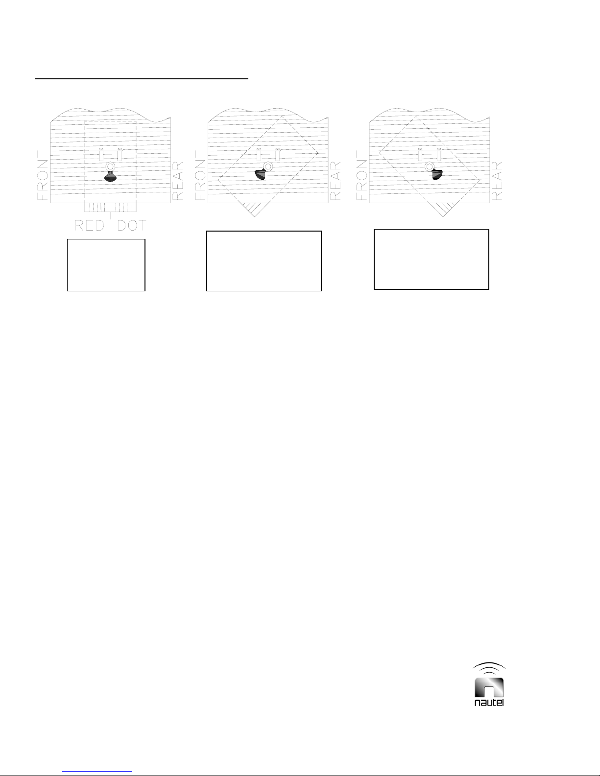
Figure 2-10 - Variometer Positioning within Loading Coil L1A (shown from tuning motor B1 view)
A
Optimum tune.
Variometer
endicular
Tap loading coils L1A and
L1B for next higher
inductance value as per
appropriate Table 2-3 (a-f).
B
Tap loading coils L1A and
L1B for next lower
inductance value as per
appropriate Table 2-3 (a-f).
C
(w) Ensure the largest adjustment range
is provided for the loading coils. If the
variometer position is:
- perpendicular, as depicted in Figure
2-10 A, the variometer is in the
optimum position and no further
adjustment is required.
- shifted as depicted in Figure 2-10 B,
turn off the transmitter and tap the
loading coils (L1A and L1B) for the
next higher inductance value as per
the appropriate Table 2-6 (a-f). Turn
the transmitter back on, allow the ATU
to tune and then recheck the
variometer’s position. If the variometer
is further away from perpendicular,
return to the previous loading coil
taps.
- shifted as depicted in Figure 2-10 C,
turn off the transmitter and tap the
loading coils (L1A and L1B) for the
next lower inductance value as per
the appropriate Table 2-6 (a-f). Turn
the transmitter back on, allow the
ATU-HP to tune and then recheck the
variometer’s position. If the variometer
is further away from perpendicular,
return the loading coils to their
previous tap(s).
(x) Ensure the largest adjustment range
is provided for the variable matching
transformer. If the inner coil is:
- centered, as depicted in Figure 2-11,
the variable matching transformer is in
the optimum position and no further
adjustment is required.
- closer to the ‘MAX LIMIT’ (see Figure
2-11), adjust T1’s input and output
taps for the next lower resistance
ratio as per Table 2-5. Turn the
transmitter back on, allow the ATU to
tune and then recheck the variable
matching transformer’s position.
Repeat if necessary to achieve
optimum position. If the variable
matching transformer is further off
centre, return to the previous T1 taps.
- Closer to the ‘MIN LIMIT’ (see Figure
2-11), adjust T1’s input and output
taps for the next higher resistance
ratio as per Table 2-5. Turn the
transmitter on, allow the ATU-HP to
tune and then recheck the variable
matching transformer’s position.
Repeat if necessary to achieve
optimum position. If the variable
matching transformer is further off
centre, return to the previous T1 taps.
Page 2-18 ATU-HP Technical Instruction Manual
Issue 2.0 Section 2 Preparation for Use and Installation

Stage 3 of Tuning Procedure
Final Setting of L and R Tuning Taps (LOCAL control, TUNE SETUP off)
Figure 2-11 - Variable Matching Transformer (shown centred, optimum tuning)
(y) Adjust the transmitter for the desired
operating power level.
(z) For DGPS applications
: If excessive
reflected power is measured, but the
L and R TUNING - NORMAL LEDs
are on, it is likely that the antenna
bandwidth is too narrow for the
radiated signal. The antenna
bandwidth may be increased by
increasing the antenna system
resistance using Nautel’s Series
Resistor Kit (optional), as detailed in
paragraph 2.6.
(aa) For NDB applications
MCW mode): If excessive reflected
power prevents the desired mod
depth from being achieved, reduce
the carrier level as needed or increase
the antenna system resistance using
Nautel’s Series Resistor Kit (optional),
as detailed in paragraph 2.6.
(bb) Adjust the ATU-HP’s spark gap (see
paragraph 2.5.1).
(transmitter in
ATU-HP Technical Instruction Manual Page 2-19
Section 2 Preparation for Use and Installation Issue 2.0

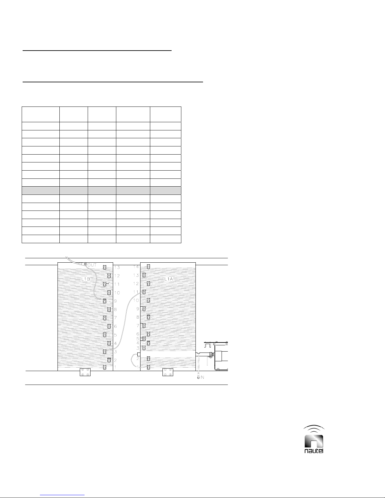
All Stages of Tuning Procedure
DGPS Applications
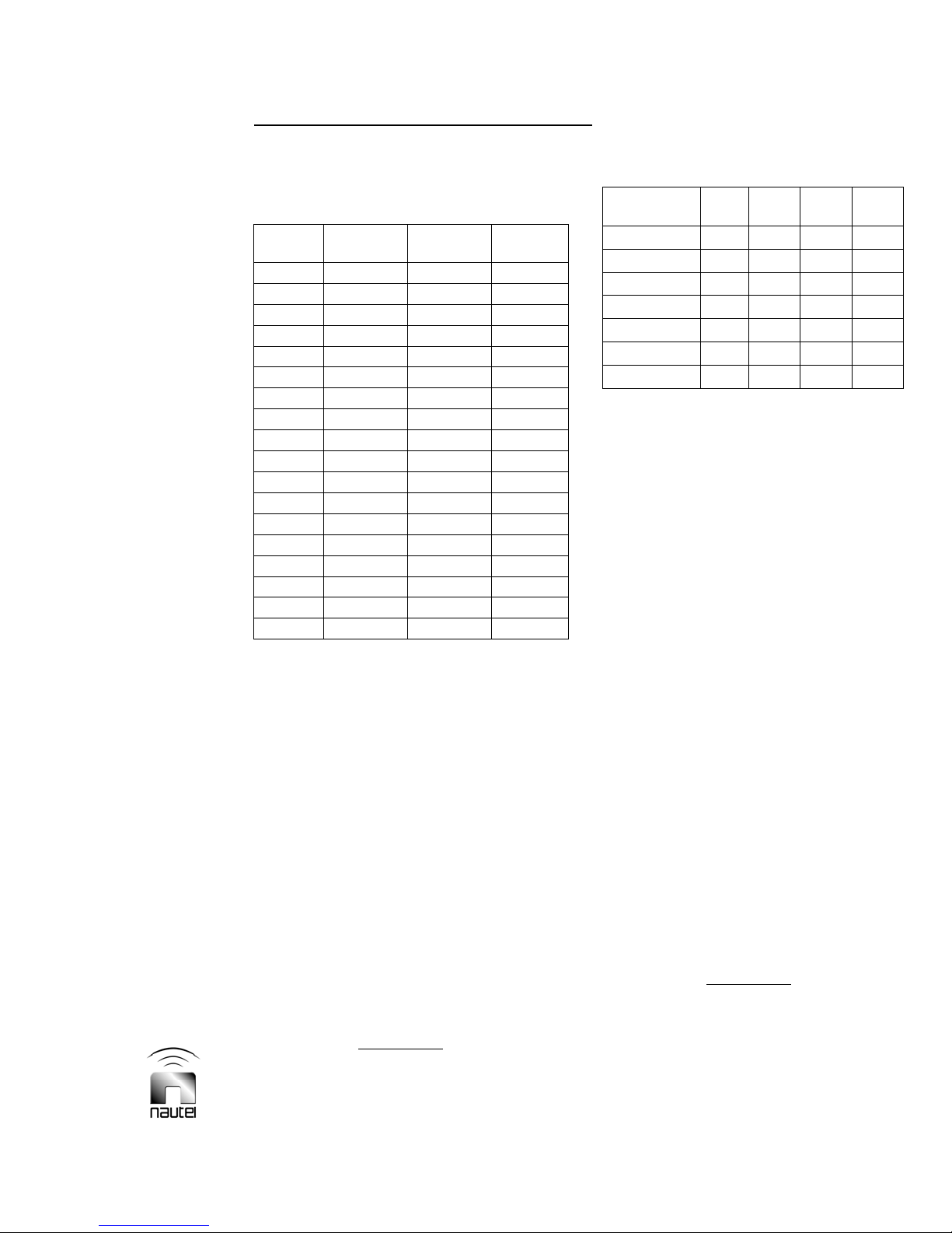
Table 2-6a: Loading Coil (DGPS) Series Connection (500-136 μH)
Inductance
(μH)
480 1 13 1 12
460 1 13 1 11
440 1 13 1 10
390 1 11 1 10
350 1 10 1 9
320 1 11 2 9
275 2 11 2 9
250 2 10 2 9
235 2 10 2 8
215 2 9 2 8
195 2 9 2 7
180 3 8 2 8
164 3 8 2 7
145 3 8 2 6
L1A
input
L1A
output
L1B
input
L1B
output
Figure 2-12a: Loading Coil (DGPS) Series Connection (500-136 μH)
(215 μH shown)
Page 2-20 ATU-HP Technical Instruction Manual
Issue 2.0 Section 2 Preparation for Use and Installation

All Stages of Tuning Procedure
DGPS Applications
Table 2-6b: Loading Coil (DGPS) Parallel Connection (135-20 μH)
Inductance
(μH)
125 2 13 1 12
110 2 12 1 11
100 2 11 1 10
90 2 10 1 9
80 2 12 4 10
70 3 10 3 9
65 3 10 3 8
58 3 11 5 9
53 3 9 5 9
46 4 8 2 6
40 4 8 3 6
36 5 7 1 7
32 5 7 2 5
26 5 6 2 6
23 3 5 4 5
L1A
input
L1A
output
L1B
input
L1B
output
Figure 2-12b: Loading Coil (DGPS) Parallel Connection (135-20 μH)
(90 μH shown)
ATU-HP Technical Instruction Manual Page 2-21
Section 2 Preparation for Use and Installation Issue 2.0
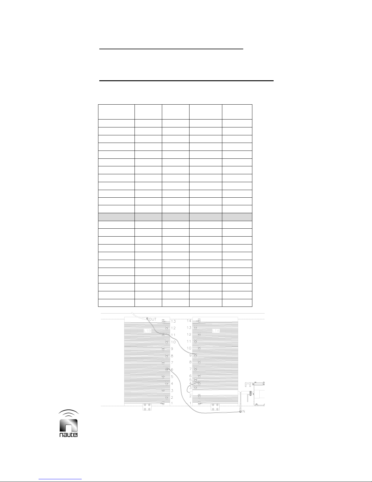
All Stages of Tuning Procedure
Low Power NDB Applications
Table 2-6c: Loading Coil (NDB Low Power) Series Connection (2700-640 μH)
Inductance
(μH)
2500 1 14 1 13
2350 1 14 1 12
2250 1 14 1 11
2100 1 14 1 10
2000 1 14 2 10
1850 1 14 3 10
1750 1 12 2 10
1625 1 12 2 9
1375 1 11 3 9
1160 2 10 3 9
1050 2 10 3 8
875 3 10 4 8
775 3 8 4 9
700 4 10 5 8
650 4 9 5 9
L1A
input
L1A
output
L1B
input
L1B
output
Figure 2-12c: Loading Coil (NDB Low Power) Series Connection (2700-640 μH)
(1375 μH shown)
Page 2-22 ATU-HP Technical Instruction Manual
Issue 2.0 Section 2 Preparation for Use and Installation
All Stages of Tuning Procedure
Low Power NDB Applications
Table 2-6d: Loading Coil (NDB Low Power) Parallel Connection (639-50 μH)
Inductance
(μH)
620 1 14 1 13
580 1 13 1 13
555 1 13 1 12
520 1 12 1 12
460 1 11 2 12
400 1 11 2 10
370 1 11 2 9
340 1 10 3 10
300 1 10 3 9
290 2 10 4 10
260 2 9 4 10
230 2 9 4 9
200 4 9 6 11
190 5 9 3 8
170 4 8 6 11
150 5 8 4 9
135 5 8 4 8
130 3 8 7 10
110 3 7 7 10
100 4 7 6 9
90 5 6 6 12
80 5 6 6 10
70 5 6 6 9
60 3 5 7 9
L1A
input
L1A
output
L1B
input
L1B
output
Figure 2-12d: Loading Coil (NDB Low Power) Parallel Connection (639-50 μH)
(200 μH shown)
ATU-HP Technical Instruction Manual Page 2-23
Section 2 Preparation for Use and Installation Issue 2.0
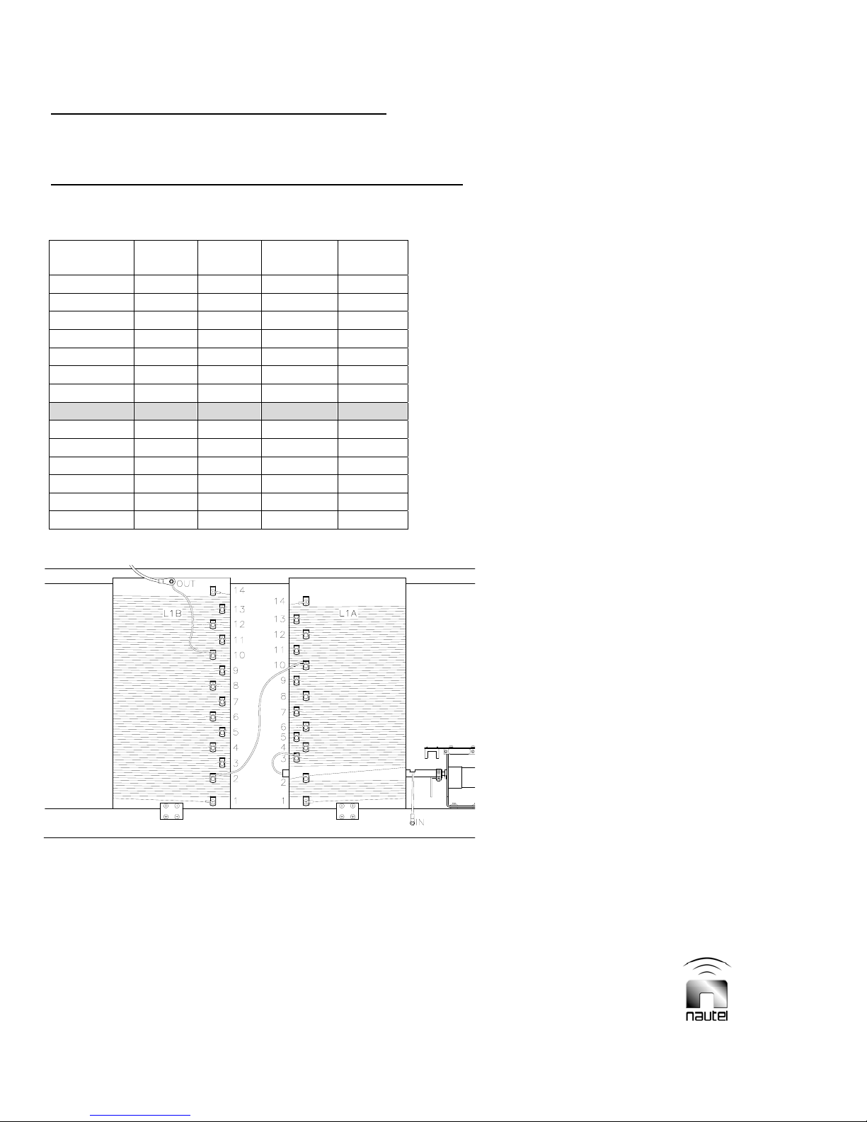
All Stages of Tuning Procedure
High Power NDB Applications
Table 2-6e: Loading Coil (NDB High Power) Series Connection (1200-300 μH)
Inductance
(μH)
1150
1050
950
840
730
680
630
580
530
480
450
400
350
310
L1A
input
1 14 1 14
1 13 1 13
1 12 1 12
1 11 1 11
2 11 1 10
2 10 1 10
2 10 1 9
3 10 2 10
3 10 2 9
3 9 2 9
4 10 3 9
4 9 3 9
4 9 4 9
4 8 4 9
L1A
output
L1B
input
L1B
output
Figure 2-12e: Loading Coil (NDB High Power) Series Connection (1200-300 μH)
(580 μH shown)
Page 2-24 ATU-HP Technical Instruction Manual
Issue 2.0 Section 2 Preparation for Use and Installation

All Stages of Tuning Procedure
High Power NDB Applications
Table 2-6f: Loading Coil (NDB High Power) Parallel Connection (299-25 μH)
Inductance
(μH)
290
260
235
220
205
190
180
165
150
135
120
110
95
90
80
70
60
55
50
40
35
33
30
29 4 6 7 9
26 4 5 7 9
L1A
input
1 14 1 14
1 13 1 13
1 12 1 12
2 13 2 12
2 12 2 12
2 12 2 11
2 11 2 11
2 11 2 10
2 10 2 10
3 10 3 10
3 10 3 9
3 9 3 9
3 9 4 9
4 9 4 9
4 8 4 9
5 8 4 9
5 8 5 9
5 6 2 9
5 6 4 9
4 5 5 9
4 5 6 9
4 7 7 9
5 7 7 9
L1A
output
L1B
input
L1B
output
Figure 2-12f: Loading Coil (NDB High Power) Parallel Connection (299-25 μH)
(110 μH shown)
ATU-HP Technical Instruction Manual Page 2-25
Section 2 Preparation for Use and Installation Issue 2.0

(kV)
Peak
Antenna
Voltage
100
80
60
40
20
10
8
6
4
2
1
.01 .02 .04 .1 .2 .4 1 2
Gap Length (Inches)
Figure 2-13 Peak Antenna Voltage Versus Spark Gap Setting
2.5.1 Adjusting the Spark Gap
Adjust the ATU-HP’s spark gap as follows:
IA is the current recorded from step (a)
X
is the reactance from step (c).
L
(a) Record the antenna current on the
ATU control/monitor PWB’s meter.
Set switch A1S11 to RF CURRENT.
(b) Turn the transmitter off.
(c) Calculate the ATU-HP reactance (X
using the following formula:
X
= 0.00628ƒcL
L
ƒ
is the operating frequency (in kHz)
c
L is the inductance (in μH) (use value
selected from the appropriate Table
2-6 (a-f).
(d) Calculate the peak ATU-HP output
voltage (V
DGPS: V
NDB: V
) using either:
PK
= 1.414 IA XL
PK
= 1.414 IA XL (1+Mod %/100)
PK
)
L
Ensure the transmitter is off when
making adjustments on the ATU-HP.
Lethal voltages are present when any
level of RF is applied to the ATU-HP.
(e) Enter the graph shown in Figure 2-13
with the peak antenna voltage
calculated in step (d) and determine
the spark gap length (in inches).
(f) Set the spark ball gap for the length
determined in step (e).
(g) Turn on the transmitter at the desired
power level and ensure no arcing of
the spark gap.
(h) Install ATU-HP covers.
WARNING
Page 2-26 ATU-HP Technical Instruction Manual
Issue 2.0 Section 2 Preparation for Use and Installation

This Page Intentionally Left Blank
ATU-HP Technical Instruction Manual Page 2-27
Section 2 Preparation for Use and Installation Issue 2.0

2.6 INCREASING ANTENNA
BANDWIDTH
If it is necessary to increase antenna
system bandwidth, as determined in
paragraph 2.5, step (z) for DGPS
applications or step (aa) for NDB
applications, incorporate the Nautel’s
Series Resistor Kit, if provided, as follows:
NOTE
The series resistor kit is factory installed if
purchased with the ATU-HP. The kit is
user-installed, using a separate
Information Sheet document, if purchased
after ATU-HP installation.
Adding series resistance will reduce the
reflected power level, but will reduce
antenna current.
WARNING
It is recommended that additional safety
precautions against accidental RF input
application be taken when working in
the vicinity of the tuning coils.
Connect grounding clip (located near
the RF input) to the RF input.
(a) Using Figure 2-14a (for DGPS
applications) or Figure 2-14b (for NDB
applications), determine the additional
series resistance by selecting the T2
tap settings that provide acceptable
reflected power. View reflected power
on the ATU control/monitor PWB’s
meter, noting switch A1S10 must be
set to REFLD PWR and switch A1S11
must be set to RF POWER.
Page 2-28 ATU-HP Technical Instruction Manual
Issue 2.0 Section 2 Preparation for Use and Installation

(
–
p (x)
DGPS Applications
ADDING SERIES RESISTANCE
With transmitter
operating in MSK
mode at desired
power level, note
reflected power on
meter
Turn transmitter off.
Change taps on T2 to
add resistance as per
Table 2-7. Turn
transmitter on.
Wait for L TUNING -
NORMAL and R
TUNING – NORMAL
LEDs to turn on
motors stop)
Is the R
TUNING–
MAX LIMIT
LED on?
NO
YES
NO YES
Turn transmitter
off. Change taps
on T1 to next
higher resistance
ratio as per Table
2-5. Turn
transmitter on.
Is reflected
power
acceptable?
Repeat para.
2.5, ste
NO
Note T2 tap settings.
Note variable matching
transformer position
(see Figure 2-12)
Is variable
matching
transformer near
optimum
position?
YES
ATU-HP
TUNED
Figure 2-14a - Flow Diagr am
ATU-HP Technical Instruction Manual Page 2-29
Section 2 Preparation for Use and Installation Issue 2.0
Adding Antenna Series Resistance (DGPS Applications)

(
p (x)
NDB Applications
ADDING SERIES RESISTANCE
Turn transmitter off.
Change taps on T2 to
add resistance as per
Table 2-7. Turn
transmitter on.
Wait for L TUNING -
NORMAL and R
TUNING – NORMAL
LEDs to turn on
motors stop)
NO YES
Turn on transmitter, in
CW mode, and set to
desired power level.
Set transmitter to
operate in MCW
mode. Increase the
modulation to the
desired level.
Can mod depth
be achieved
with acceptable
reflected power
level?
Repeat para.
2.5, ste
NO
Note T2 tap settings.
Note variable matching
transformer position
(see Figure 2-12)
Is variable
matching
transformer near
optimum
position?
Is the R
TUNING–
MAX LIMIT
LED on?
Figure 2-14b - Flow Diagr am – Adding Antenna Series Resistance (NDB Applications)
Page 2-30 ATU-HP Technical Instruction Manual
Issue 2.0 Section 2 Preparation for Use and Installation
NO
YES
Turn transmitter
off. Change taps
on T1 to next
higher resistance
ratio as per Table
2-5. Turn
transmitter on.
YES
ATU-HP
TUNED

Table 2-7: T2 Taps vs Series Resistance
T2 Tap Settings
Series
Resistance
(Ω)
0 1 1 3 1
0.8 7 1 6 1
1.0 7 1 5 1
1.4 7 1 4 1
2.0 7 1 3 1
3.1 8 1 6 1
4.1 8 1 5 1
5.6 8 1 4 1
(terminated on positions 1 through 9 as in Fig. 2-16)
Wires
terminating on
A1TB1-7/8 (A)
Wire terminating
on L1A-input (B)
Core connection
from external
load resistor
Shield connection
from external
load resistor
Figure 2-15 Partial View of Series Resistance Transformer T2 Taps
(shown connected to provide an additional 0.8 Ω series resistance)
ATU-HP Technical Instruction Manual Page 2-31
Section 2 Preparation for Use and Installation Issue 2.0


ATU-HP Technical Instruction Manual Page 2-32
Section 2 Preparation for Use and Installation Issue 2.0
Figure 2-16 ATU-HP – Dimensional Information and Mounting Options

ATU-HP
TECHNICAL INSTRUCTION MANUAL
Section 3 OPERATING INSTRUCTIONS
3.1 INTRODUCTION
This section provides the information required
to place the ATU-HP in operation. The
ATU-HP will normally be unattended during
use. The following instructions are intended
for persons involved in testing or
maintenance of the equipment.
WARNING
Use extreme caution near the tuning
coils. Extremely high RF voltages, that
may arc many inches of air breakdown
path
and cause severe RF burns, are
present when an RF input of any level is
applied to the ATU-HP.
3.2 EMERGENCY SHUTDOWN
There are no special procedures to be
observed if an emergency shutdown is
required. Remove RF input by having
transmitter's RF output turned off or by
disconnecting RF input coaxial cable from RF
input connector J3.
.
3.3 CONTROLS AND INDICATORS
All of the controls and indicators for the
automatic antenna tuning unit are located on
the ATU control/monitor PWB (A1). Figure
3-1 and Table 3-1 identify and describe the
controls and/or indicators on the ATU
control/monitor PWB. It is recommended the
operator/maintainer be familiar with the ATU
controls and indicators before placing the
ATU-HP into service and/or attempting to
perform fault diagnostics.
NOTE
On some assembly detail drawings,
numbered callouts are provided to crossreference the control/indicator to the
description table.
The names used in the PANEL MARKING
column of the controls and indicators tables
are intended to be the closest possible
representation to the item’s label/silkscreen.
ATU-HP Technical Instruction Manual Page 3-1
Section 3 Operating Instructions Issue 2.0

M1
R10
Q9
Q5
ECB
CR5
R11
R12
R13
Q10
Q6
ECB
CR6
R14
R15
R16
Q11
Q7
ECB
CR7
R17
R18
R19
Q12
Q8
ECB
CR8
R20
R21
2
CR13
1
CR14
CR15
CR16
T6
T2
2 1
1
2
4 3
431
2
T3
6
R22
T5
5
CR9
CR10
CR17
CR18
CR19
CR11
CR12
CR20
CR21
CR22
CR23
CR24
CR25
CR26
CR27
CR28
DS20 R70 R51 S10 S11
DS19
DS21
FAN FAIL12
DS19 DS21
R118
CPU OK
C6
R29
C7
R30
GND
TP1
C8
R31
C9
R32
M1
CR38
R109
R110
CR39
CR40 CR43
R111
R23
R24
R25
R26
METER
R72
ANT CUR
SAMPLE
C21
C19
R51
R49
R57
CR32
R56
C20
R74
C18
R39
CR30
R81
R50
R48
R55
R46
R70
R73
C23
R71
TP4TP5
C22
E5
C
E6
INCREASE
CAL
R28R33
R42
R27
C10
C11
4
R38
R47
CR31
R40
R45
CR29
C12
C14
C15
R43
R44
C16
C13
C17
E3
S2
R52
R63
R62
R64
E4
E1
R34
R53
R41
R54
E2
DECREASE
B
S3
INHIBIT
R66
R67
R68
LOCAL/ XMTR
REMOTE
A
+-
C79
R TUNINGL TUNING
R94
S5S1
R95
R96
L TUNING R TUNING
DS5
S6
DS6
DS7
DS8
DS9
S7
DS10
R83
R76
R77
R78
R79
R87
R84
R88
R85
R89
DS2DS1
R90
ON/OFF
S8S4
R80R69
DS3
SETUP
TUNE
R91R86
R92
S9
+5V
RF POWERFWD PWR
S10 S11
RF CURRENTREFLD PWR
C24 C29 C31
U1
U2
R97
R98
R99
NORMAL
INHIBIT
TP2
GND
DS12
DS13
DS14
DS15
DS16
DS17
C30
U3
+12V-B+12V-A
MAX LIMIT
INCREASE
DECREASE
MIN LIMIT
C25
C26
C27
C28
R93
DS4
C40
123
U5
CR34
U4
C36
C37
R102
R103
R105
R104
R106
R107
CR35
CR36
C38
CR37
C32
C33
C39
C34
C35
C41
4
123
U6
4
F1
R101R100
DS18DS11
F2
DS20
R119
R114
R115
C50
C51
R116
R117
C55
CR41
R120
C47
R121
C48
CR42
C49
U8
C44 C43
Y1
C46 C45
R112
CR44
CR45
R113
C52
CR46
CR47
C53
C42
U7
R108
J1
1
C54
4
78 65
34 21
SPLIT
SINGLE
R123
R124
R122
R130
C56
C62
U11
CR48
CR51
CR49
CR52
CR50
CR53
+
C58
C59
U10
C60
L5
C61
C63
C57
CR54
321
U9
T7
LINE
LINE
123
R125
R126
Q13
R127
R128
Q14
R129
C64
GND
LINE NEUT N/C
GND
Q15 Q16
CR55
CR56
C67
R141
TP3
GND
R134
R135
R136
R137
R138
R139
R140
C73
C74
U15
C65
R131
R132
C66
R133
N/C NEUTN/C
456
TB2
R142
R143
R144
R145
C68
C69
C70
C71
C72
CR59
CR60
C75
R152
1
R153
R154
R155
R156
R148
R149
R150
R151
C76
R157
C78
C80
L7
C77
R147
U12U13
CR57
CR58
J2
L6
1
J3
R146
R158
U14
TX/RX TX/RX DE/RE
GND
ISOLATED
+5V
TB3
230VAC
115VAC 115VAC
123456789101112
A - C
S1 – S9
DS1 – DS3
Fig. 3-1 - Part of ATU Control/Monitor PWB A1 (NAPC144
Page 3-2 ATU-HP Technical Instruction Manual
Issue 2.0 Section 3 Operating Instructions
DS4
DS11
DS18
A/01)
DS5 – DS10
DS12 - DS17
F1
F2

Table 3-1: ATU Control/Monitor PWB Controls and Indicators
REF DES
A1DS1
A1DS2
A1DS3
A1DS4
A1DS5
A1DS6
A1DS7
A1DS8
A1DS9
A1DS10
A1DS11
A1DS12
ATU-HP Technical Instruction Manual Page 3-3
Section 3 Operating Instructions Issue 2.0
PANEL
MARKING
LOCAL/REMOTE
XMTR OFF
TUNE SETUP
+5V
L TUNING – MAX
LIMIT
L TUNING –
INCREASE
L TUNING –
NORMAL
L TUNING –
DECREASE
L TUNING – MIN
LIMIT
L TUNING –
INHIBIT
+12V-A
R TUNING –
MAX LIMIT
DESCRIPTION
When turned on (amber), indicates the ATU-HP is in local
mode.
When turned on (amber), indicates the transmitter‘s remote
power trim level has been set to zero volts, via a serial
communication link, using the XMTR ON/OFF switch (A1S8).
If the transmitter is set to remote mode, the transmitter’s
power will be reduced to 0 W.
When turned on (red), indicates the ATU-HP is in tuning
mode, as a result of the TUNE SETUP (A1S9) switch being
pressed. This LED must be off during normal operation.
When turned on (green), indicates the +5 V regulated low
voltage power supply is present.
When turned on (red), indicates that the ATU-HP reached a
maximum inductance limit while attempting to tune by
increasing the loading coil inductance. The motor will be
inhibited from causing further inductance increase.
When turned on (amber), indicates that the ATU-HP is
attempting to tune by increasing the loading coil inductance.
When turned on (green), indicates that the ATU-HP’s loading
coils are properly tuned.
When turned on (amber), indicates that the ATU-HP is
attempting to tune by decreasing the loading coil inductance.
When turned on (red), indicates that the ATU-HP reached a
minimum inductance limit while attempting to tune by
decreasing the loading coil inductance. The motor will be
inhibited from causing further inductance decrease.
When turned on (red), indicates that the ATU-HP’s automatic
inductance tuning has been inhibited by pressing the L
TUNING – INHIBIT switch (A1S3) or via remote control.
When turned on (green), indicates the +12 V-A regulated low
voltage power supply, which supplies the inductance tuning
control circuitry, is present.
When turned on (red), indicates that the ATU-HP reached a
maximum resistive matching limit while attempting to tune by
increasing the input resistance. The motor will be inhibited
from causing further resistive match increase.

Table 3-1: ATU Control/Monitor PWB Controls and Indicators (Continued)
REF DES
A1DS13
A1DS14
A1DS15
A1DS16
A1DS17
A1DS18
A1DS19
A1DS20
A1DS21
A1-A
A1-B
A1-C
PANEL
MARKING
R TUNING –
INCREASE
R TUNING –
NORMAL
R TUNING –
DECREASE
R TUNING – MIN
LIMIT
R TUNING –
INHIBIT
+12V-B
FAN FAIL 1
CPU OK
FAN FAIL 2
Reflected Power
Meter Scale
Forward Power
Meter Scale
Antenna Current
Meter Scale
DESCRIPTION
When turned on (amber), indicates that the ATU-HP is
attempting to tune by increasing the variable matching
transformer’s input resistance.
When turned on (green), indicates that the ATU-HP’s variable
matching transformer is properly tuned.
When turned on (amber), indicates that the ATU-HP is
attempting to tune by decreasing the variable matching
transformer’s input resistance.
When turned on (red), indicates that the ATU-HP reached a
minimum resistive matching limit while attempting to tune by
decreasing the input resistance. The motor will be inhibited
from causing further resistive match decrease.
When turned on (red), indicates that the ATU-HP’s automatic
resistive tuning has been inhibited by pressing the R TUNING
– INHIBIT switch (A1S7) or via remote control.
When turned on (green), indicates the +12 V-B regulated low
voltage power supply, which supplies the resistive tuning
control circuitry, is present.
When turned on (red), indicates cooling fan 1 (B2) has failed.
When flashing (green), indicates the ATU control/monitor
PWB’s microcontroller is functional.
When turned on (red), indicates cooling fan 2 (B3) has failed.
Wire jumper that determines the reflected power scale to
read on meter A1M1. Jumper connects to screw terminal E1
for the 0 - 400 W scale. Jumper connects to screw terminal
E2 for the 0 - 120 W scale.
Wire jumper that determines the forward power scale to read
on meter A1M1. Jumper connects to screw terminal E3 for
the 0 - 4000 W scale. Jumper connects to screw terminal E4
for the 0 - 1200 W scale.
Wire jumper that determines the antenna current scale to
read on meter A1M1. Jumper connects to screw terminal E5
for the 0 -10 A scale. Jumper connects to screw terminal E6
for the 0 – 30 A scale.
Page 3-4 ATU-HP Technical Instruction Manual
Issue 2.0 Section 3 Operating Instructions

Table 3-1: ATU Control/Monitor PWB Controls and Indicators (Continued)
REF
DES
A1F1
A1F2
A1M1
A1R51
A1R70
A1S1
A1S2
A1S3
PANEL
MARKING
Ac Input Fuses
Meter
ANT CUR
SAMPLE
METER CAL
L TUNING –
INCREASE
L TUNING –
DECREASE
L TUNING –
INHIBIT
DESCRIPTION
Fuse the ac power source voltage applied to A1TB2-1 (A1F2)
and A1TB2-3 (A1F1) at 0.25 A.
Analog meter that displays the following ATU-HP parameters:
Forward power, on one of two scales (0 - 4000 W or 0 -
1200 W), when switch A1S10 is set to FWD PWR and switch
A1S11 is set to RF POWER.
Reflected power, on one of two scales (0 – 400 W or 0 120 W), when switch A1S10 is set to REFLD PWR and
switch A1S11 is set to RF POWER.
Antenna current, on one of two scales (0 – 30 A or 0 – 10 A),
when switch A1S11 is set to RF CURRENT.
The modulation 0 – 100% scale is not used in the ATU-HP.
Factory adjusted to provide an antenna current sample,
monitored by the associated transmitter via a serial link, of
4 V when the antenna current is 30 A.
Factory adjusted to set the series resistance of meter A1M1
to a precise value for meter accuracy.
When pressed (in local mode only), causes a manual
increase in the ATU-HP’s loading coil inductance. If the
ATU-HP was tuned, the L TUNING – DECREASE LED will
turn on, indicating the ATU-HP is no longer tuned. The ATUHP will restore a tuned condition, if auto tuning is not
inhibited.
When pressed (in local mode only), causes a manual
decrease in the ATU-HP’s loading coil inductance. If the
ATU-HP was tuned, the L TUNING – INCREASE LED will
turn on, indicating the ATU-HP is no longer tuned. The ATUHP will restore a tuned condition, if auto tuning is not
inhibited.
When pressed (in local mode only), disables the ATU-HP’s
automatic inductance tuning function. Associated L TUNING
– INHIBIT LED will turn on.
ATU-HP Technical Instruction Manual Page 3-5
Section 3 Operating Instructions Issue 2.0

Table 3-1: ATU Control/Monitor PWB Controls and Indicators (Continued)
REF DES
A1S4
A1S5
A1S6
A1S7
A1S8
A1S9
A1S10
A1S11
PANEL
MARKING
LOCAL/REMOTE
R TUNING –
INCREASE
R TUNING –
DECREASE
R TUNING –
INHIBIT
XMTR ON/OFF
TUNE SETUP
FWD PWR/
REFLD PWR
RF POWER/
RF CURRENT
DESCRIPTION
When pressed, toggles between local and remote operation.
In local mode, indicated by LED A1DS1 turning on, all remote
controls are disabled. If a serial link was established between
the ATU-HP and a Nautel transmitter, the antenna current
feedback loop is not intact.
In remote mode, indicated LED A1DS1 turning off, all local
pushbuttons are disabled.
When pressed (in local mode only), causes a manual
increase in the variable matching transformer’s input
resistance. If the ATU-HP was tuned, the R TUNING –
DECREASE LED will turn on, indicating the ATU-HP is no
longer tuned. The ATU-HP will restore a tuned condition, if
automatic tuning is not inhibited.
When pressed (in local mode only), causes a manual
decrease in the variable matching transformer’s input
resistance. If the ATU-HP was tuned, the R TUNING –
INCREASE LED will turn on, indicating the ATU-HP is no
longer tuned. The ATU-HP will restore a tuned condition, if
automatic tuning is not inhibited.
When pressed (in local mode only), disables the ATU-HP’s
automatic resistive tuning function. Associated R TUNING –
INHIBIT LED will turn on.
When pressed (with ATU-HP in local mode only), with a serial
communication link connected between the ATU-HP and a
Nautel transmitter, sets the transmitter’s remote power trim
level to zero volts. Associated LED (A1DS2) will also turn on.
If the transmitter is set to remote mode, the transmitter’s
power will be reduced to 0 W.
When pressed (in local mode only), allows for initial tuning of
the loading coil inductance. The TUNE SETUP LED
(A1DS3) will be on. Once tuning is complete, switch must be
pressed again to exit the mode and resume normal operation.
Two-position switch that determines which power parameter,
FWD PWR (forward power) or REFLD PWR (reflected
power), can be monitored by meter A1M1. Switch A1S11
must be set to the RF POWER position to indicate either
parameter on the meter.
Two-position switch that determines which parameter, RF
POWER (forward or reflected power) or RF CURRENT
(antenna current) will be indicated by meter A1M1.
Page 3-6 ATU-HP Technical Instruction Manual
Issue 2.0 Section 3 Operating Instructions

ATU-HP
TECHNICAL INSTRUCTION MANUAL
Section 4 TESTING AND ADJUSTMENT
4.1 INTRODUCTION
This section contains step-by-step
calibration procedures for the antenna
tuning unit (ATU) using precision test
equipment and a functional test procedure
using integral meters.
NOTE
It is recommended that personnel who are
not familiar with detailed circuit theory or do
not realize the impact a specific adjustment
will have on other steps, follow the
instructions in the order they are
presented. These adjustments should be
performed during initial turn-on and after
major repairs or a frequency change.
4.2 OPERATING PRECAUTIONS
Operation of the ATU-HP is fully automatic
except when the manual override switches
are activated. Maintainers should read and
fully understand the Operating Instructions
section, particularly the controls and
indicators section.
4.3 FUNCTIONAL TESTS
Successful completion of the following
tests will verify the ATU-HP circuits are
within factory specifications.
4.3.1 General
The functional tests should be performed
and the results recorded for comparison
with past and future test results, as a
routine part of scheduled maintenance
checks and as the first step in
troubleshooting procedures.
4.3.1.1 The functional test procedures are
provided in a step-by-step format. This
method of presentation will permit a person
who is unfamiliar with the transmitter to
perform the functional tests in a logical
sequence. It is recommended the
procedures be completed in sequence, as
each procedure establishes switch settings
and contains prerequisites for subsequent
procedures.
4.3.2 Initial Settings
Set the controls as follows prior to initial
turn-on:
(a) Verify transmitter RF output is turned
off.
(b) Gain access to the interior of the ATU
cabinet by disengaging the front
cover’s pull-down latches. Carefully
remove front cover.
WARNING
Connect grounding clip (located near
the RF input) to the RF input.
(c) Press LOCAL/REMOTE switch A1S4.
LOCAL LED A1DS1 will turn ON.
(d)
Press INHIBIT L TUNING switch
A1S3. INHB L TUNING LED A1DS10
will turn ON.
(e) Press INHIBIT R TUNING switch
A1S7. INHB R TUNING LED A1DS17
will turn ON.
Extremely high, potentially lethal, RF voltages are present in the ATU-HP when an RF
input is being applied. Use extreme caution during maintenance or troubleshooting
inside the ATU-HP cabinet. Where possible, turn off the associated transmitter.
ATU-HP Technical Instruction Manual Page 4-1
Section 4 Testing and Adjustment Issue 2.0
WARNING

4.3.3 Manual Check Of Tuning
Drive
Check tuning mechanism as follows:
4.3.3.1 INDUCTIVE TUNING MOTOR:
NOTE
Inductive tuning motor B1 rotates very
slowly. To monitor its rotation, note the
position of the L TUNING limit switch
actuator, which is located on the coil shaft
near the motor.
(a) Monitor travel of the limit switch
actuator while pressing and holding
INCREASE L switch A1S1.
NOTE
Release INCREASE L switch if the motor
stalls before the maximum inductance limit
is reached (L MAX LIMITLED turns on).
(b) The tuning drive mechanism shall
operate smoothly, with no apparent
binding or excessive loading. The limit
switch actuator shall rotate such that it
approaches limit switch detector U2
(nearest the front of the cabinet).
(c) Inductive tuning drive motor B1 shall
turn off when the maximum inductance
limit is obtained (L MAX LIMIT LED is
on).
(d) Release INCREASE L switch when
tuning drive mechanism stops.
(e) Monitor travel of the limit switch
actuator while pressing and holding
DECREASE L switch A1S2.
NOTE
Release DECREASE L switch if the motor
stalls before the minimum inductance limit
is reached (L MIN LIMITLED turns on).
(f) The tuning drive mechanism shall
operate smoothly, with no apparent
binding or excessive loading. The limit
switch actuator shall rotate such that it
approaches limit switch detector U1
(nearest the rear of the cabinet).
(g) Tuning drive motor B1 shall turn off
when the minimum inductance limit is
obtained (L MIN LIMIT LED is on).
(h) Release DECREASE L switch when
tuning drive mechanism stops.
(i) Monitor travel of the limit switch
actuator while pressing and holding
INCREASE L switch.
(j) Release INCREASE L switch when
limit switch actuator is pointing towards
the ATU bottom.
4.3.3.2 RESISTIVE TUNING MOTOR
NOTE
To monitor the rotation of the resistive
tuning motor, note the position of the R
TUNING limit switch actuator, which is
located on the inner coil of variable
matching transformer A2 (see Figure
2-11).
(a) Monitor travel of the limit switch
actuator while pressing and holding
INCREASE R switch A1S5.
NOTE
Release INCREASE R switch if the motor
stalls before the maximum resistance limit
is reached (R MAX LIMITLED turns on).
(b) The tuning drive mechanism shall
operate smoothly, with no apparent
binding or excessive loading. The limit
switch actuator shall move towards the
rear of the ATU.
Extremely high, potentially lethal, RF voltages are present in the ATU-HP when an RF
input is being applied. Use extreme caution during maintenance or troubleshooting
inside the ATU-HP cabinet. Where possible, turn off the associated transmitter.
Page 4-2 ATU-HP Technical Instruction Manual
Issue 2.0 Section 4 Testing and Adjustment
WARNING

(c) Tuning drive motor A2B1 shall turn off
when the maximum resistance limit is
obtained (R MAX LIMIT LED is on).
(d) Release INCREASE R switch when
tuning drive mechanism stops.
(e) Monitor travel of the limit switch
actuator while pressing and holding
DECREASE R switch A1S6.
(f) The tuning drive mechanism shall
operate smoothly, with no apparent
binding or excessive loading. The limit
switch actuator shall move towards the
front of the ATU.
(g) Tuning drive motor A2B1 shall turn off
when the minimum resistance limit is
obtained (R MIN LIMIT LED is on).
(h) Release DECREASE R switch when
tuning drive mechanism stops.
(i) Monitor travel of the limit switch
actuator while pressing and holding
INCREASE R switch.
(j) Release INCREASE R switch when
the limit switch actuator is centered
between the R MAX LIMIT and R MIN
LIMIT positions.
4.3.4 Initial Check of RF Tuning
and Automatic Operation
Check the tuning of RF circuits and the
operation of automatic tuning drive circuits
as follows:
(a) Press INHIBIT L TUNING switch
A1S3. INHB L TUNING LED A1DS10
will turn off.
(b) Press INHIBIT R TUNING switch
A1S7. INHB R TUNING LED A1DS17
will turn off.
(c) Establish two-way communications
with the transmitter site.
NOTE
The RF output of the transmitter must be
monitored and controlled at the transmitter
during the initial tuning of the ATU-HP.
(d) Set FWD PWR/REFLD PWR switch
A1S10 to FWD PWR.
(e) Restore RF circuit integrity by
removing any secondary safety
precautions that prevented accidental
RF application (see warning following
paragraph 4.3.2).
(f) Apply RF power to the ATU-HP by
turning on the transmitter, at a reduced
power level (use CW mode for NDB
transmitters). Set carrier level, as
indicated on transmitter, to 50 W
initially.
(g) The ATU-HP will tune until the
NORMAL L (A1DS7) and NORMAL R
(A1DS14) turn on.
(h) Increase transmitter power to 100 W.
(i) Once a tuned condition has been
restored (NORMAL L and NORMAL R
LEDs on), press and hold the
INCREASE L switch until the
DECREASE L LED turns on.
(j) The DECREASE L LED (A1DS8) will
turn on and the ATU-HP will re-tune to
a NORMAL indication.
Extremely high, potentially lethal, RF voltages are present in the ATU-HP when an RF
input is being applied. Use extreme caution during maintenance or troubleshooting
inside the ATU-HP cabinet. Where possible, turn off the associated transmitter.
ATU-HP Technical Instruction Manual Page 4-3
Section 4 Testing and Adjustment Issue 2.0
WARNING

(k) Once a tuned condition has been
restored (NORMAL L and NORMAL R
LEDs on), press and hold DECREASE
L switch until the INCREASE L LED
turns on.
(l) The INCREASE L LED (A1DS6) will
turn on and the ATU-HP will re-tune to
a NORMAL indication.
(m) Once a tuned condition has been
restored (NORMAL L and NORMAL R
LEDs on), press and hold DECREASE
R until the INCREASE R LED turns on.
(n) The INCREASE R LED (A1DS13) will
remain on while the ATU-HP re-tunes
to a NORMAL indication.
(o) Once a tuned condition has been
restored (NORMAL L and NORMAL R
LEDs on), press and hold INCREASE
R switch until the DECREASE R LED
turns on.
(p) The DECREASE R LED (A1DS15) will
remain on while the ATU-HP re-tunes
to a NORMAL indication.
4.3.5 Final Tuning of RF Circuits
Once automatic tuning circuit has assumed
control of the tuning coil drive mechanism
and a reflected power null has been
obtained, the RF circuits can be checked
for optimum tuning as follows.
NOTE
There are two scales for each of the
forward power, reflected power and
antenna current parameters on meter
A1M1. Verify the meter scale used by
noting the position of scale select jumpers
E1 through E6 on the control/monitor PWB
(A1). Refer to Figure 3-1 to locate these
jumpers and to Table 3-1 for details on
jumper settings
The MODULATION scale on meter A1M1
is not used.
(a) Turn on the transmitter (in the CW
mode of operation for NDB
transmitters) and set it for desired RF
carrier power.
(b) Set RF POWER/RF CURRENT switch
(A1S11) to RF POWER.
(c) Set FWD PWR/REFLD PWR switch
(A1S10) to FWD PWR.
(d) The forward power indication on meter
A1M1 should be similar to the forward
power indication on the transmitter's
RF Power TEST meter, less any loss
introduced by the coaxial cable
between the transmitter and ATU-HP.
(d) Set FWD PWR/REFLD PWR switch to
REFLD PWR.
(e) The reflected power indication on
meter A1M1 should be not greater
than 4% of the forward power.
(f) Set RF POWER/RF CURRENT switch
(A1S11) to RF CURRENT.
(g) Record the RF CURRENT indication
on the appropriate ANTENNA
CURRENT scale of meter A1M1 when
the transmitter is operating at desired
RF power level (in the CW mode for
NDB transmitters), and RF circuits are
tuned for minimum reflected power.
Extremely high, potentially lethal, RF voltages are present in the ATU-HP when an RF
input is being applied. Use extreme caution during maintenance or troubleshooting
inside the ATU-HP cabinet. Where possible, turn off the associated transmitter.
Page 4-4 ATU-HP Technical Instruction Manual
Issue 2.0 Section 4 Testing and Adjustment
WARNING

4.4 NON-STANDARD
ADJUSTMENTS
The following procedures are considered to
be non-standard and may only be required
under unique circumstances.
4.4.1 Antenna Current Meter
Calibration
A calibrated current probe (Nautel Part #
195-9131) which aids in calibrating the
antenna current meter is available from
Nautel. This probe may be provided with
equipment delivery upon customer request.
If necessary, calibrate the monitored
antenna current signals as follows:
(a) Turn off the associated transmitter.
Remove the ATU-HP’s front cover.
(b) Temporarily insert a calibrated current
probe in series with the wires
terminating on TB1-5 and TB1-6 of the
ATU control/monitor PWB.
(c) Turn on the associated transmitter at
the desired power level. Compare the
antenna current readings of the ATU
control/monitor PWB meter (A1M1)
and the current probe.
(d) If the readings in step (c) are within 5%
of each other, meter A1M1 is
calibrated. If not, proceed to step (h).
(e) Using a digital multimeter, measure the
dc voltage between TP5 of ATU
control/monitor PWB A1 and ground
(TP1, TP2 or TP3).
(f) Enter the antenna current reading
(I
) into the following formula:
ANT
V = I
(in amperes)/7.5
ANT
(g) If the voltage measured in step (e) is
within 2% of the voltage (V) calculated
in step (f), the ATU control/monitor
PWB is functioning properly. If not,
adjust the ANT CUR SAMPLE
potentiometer (R51) on the ATU
control/monitor PWB until the voltage
at TP5 is the same as the voltage
calculated in step (f).
(h) If the readings in step (c) differ by more
than 5%, turn off the transmitter.
(i) With the ATU control/monitor PWB’s
RF POWER/RF CURRENT switch
(A1S11) set to RF POWER, measure
the resistance between A1TP4 and
ground. If necessary, adjust METER
CAL potentiometer A1R70 for a
resistance reading of 300 Ω.
(j) Repeat steps (c) and (d).
(k) When calibration is complete, turn off
the associated transmitter.
(l) Remove the calibrated current probe
inserted in step (b), reconnect wiring to
TB1-5 and TB1-6 of the ATU control/
monitor PWB and install the ATU-HP’s
front cover.
(m) Return the transmitter and ATU-HP to
service.
Extremely high, potentially lethal, RF voltages are present in the ATU-HP when an RF
input is being applied. Use extreme caution during maintenance or troubleshooting
inside the ATU-HP cabinet. Where possible, turn off the associated transmitter.
ATU-HP Technical Instruction Manual Page 4-5
Section 4 Testing and Adjustment Issue 2.0
WARNING


ATU-HP
TECHNICAL INSTRUCTION MANUAL
Section 5 SYSTEM LEVEL TROUBLESHOOTING
5.1 GENERAL
This section contains scheduled and
corrective maintenance information for the
ATU-HP. Fault symptoms should be
analyzed to determine the corrective action
required.
5.2 SCHEDULED MAINTENANCE
Scheduled maintenance consists of
performing a visual inspection of the
ATU-HP at scheduled intervals. The
recommended minimum time between
scheduled maintenance visits is one year.
Local operating and environmental
conditions may dictate more frequent visits
and in remote sites, less frequent visits
may be acceptable. Experience and
system reliability will determine the most
practical schedule for a specific installation.
(a) Before performing any maintenance on
the ATU-HP, turn off the associated
transmitter. Remove the ATU-HP’s
front cover.
5.2.1 Cleaning the ATU-HP
Clean the ATU-HP cabinet using a
vacuum cleaner and a soft-bristle brush to
remove loose dirt. Clean, damp rags
should be used to remove dirt that cannot
be vacuumed. NEVER
air to clean the ATU-HP.
use compressed
5.2.2 Checking Hardware
In most cases, a visual inspection of
general hardware should suffice. More
critical, high current connections, such as
those made to the RF output’s teflon
insulator, the tuning coils (L1A and L1B)
and the matching transformers (T1 and
T2), should be checked and tightened with
the proper tools.
- Ensure the proper sized tools are
used to prevent damaging the
hardware. In most cases, hardware is
metric.
- A mounting surface or terminal that
has changed colour is indicative of a
loose hardware connection.
- Multi-stranded cables installed on
terminal strips MUST
5.3 CORRECTIVE MAINTENANCE
Corrective maintenance procedures consist
of identifying and correcting defects or
deficiencies that arise during operation of
the transmitter. In some cases, local/
remote alarm signals will be generated
when a malfunction occurs. The nature of
the fault and station policy will dictate
whether immediate maintenance response
is necessary.
be re-torqued.
Extremely high, potentially lethal, RF voltages are present in the ATU-HP when an RF
input is being applied. Use extreme caution during maintenance or troubleshooting
inside the ATU-HP cabinet. Where possible, turn off the associated transmitter.
ATU-HP Technical Instruction Manual Page 5-1
Section 5 System Level Troubleshooting Issue 2.0
WARNING

5.3.1 Replacing a Failed Fan
If the ATU control/monitor PWB’s FAN
FAIL 1 or FAN FAIL 2 LED is turned on
(red), cooling fan B2 or B3, respectively,
has failed. The cooling fans are located on
a fan assembly mounted on the bottom of
the ATU-HP cabinet (see Figure MD-1).
Replace a failed fan as follows:
(a) Turn off the associated transmitter.
Remove the ATU-HP’s front cover.
(b) Remove the four M6 nuts that secure
the fan assembly to the bottom of the
ATU-HP cabinet.
(c) Swing the fan assembly out of the
ATU-HP cabinet.
(d) Remove the failed fan (B2 or B3) from
the fan assembly by removing the four
securing screws. Remove the quickdisconnect connectors associated with
the fan. Note each connection for reinstallation purposes.
(e) Install the replacement fan (available
from Nautel, Part # 195-9082) using
the hardware removed in step (d).
(f) Connect the replacement fan’s wiring
by mating the quick-disconnect
connectors removed in step (d).
(g) Secure the fan assembly to the bottom
of the ATU-HP cabinet using the
hardware removed in step (b).
(h) Install the ATU-HP’s front cover and
restore the transmitter and ATU-HP to
operation.
5.3.2 Checking/Replacing the
Inductive Tuning Motor
There is no alarm that indicates the failure
of the ATU-HP’s inductive tuning motor.
The easiest way to check its operation is
by attempting manual inductance
adjustments and listening for motor
operation. The inductive tuning motor (B1)
is located to the right of tuning coil L1A
(see Figure MD-1). Check and, if
necessary, replace a failed inductive
tuning motor as follows:
(a) Remove the ATU-HP’s front cover.
Turn off the associated transmitter.
(b) In LOCAL mode, check the operation
of the inductive tuning motor (B1) by
pressing and holding the L TUNING -
INCREASE (A1S1) or L TUNING –
DECREASE (A1S2) switch, assuming
the L TUNING – MAX LIMIT or MIN
LIMIT LED is not turned on.
(c) If motor operation can be heard or the
limit actuator moves, the motor is
functional. If so, set the ATU-HP to
REMOTE, turn on the associated
transmitter, reinstall the ATU-HP’s front
cover and restore the transmitter to its
desired power level.
(d) If motor operation can be heard, but
the limit actuator does not move, check
the clamp on the motor drive shaft. If
the clamp is loose, verify proper
orientation of the limit actuator and the
inner coil. Position the inner coil
perpendicular to the tuning coil (red dot
on the inner coil at the bottom). The
limit actuator should face down (as in
Figure 2-10a). Tighten the clamp. Set
the ATU-HP to REMOTE, turn on the
associated transmitter, reinstall the
ATU-HP’s front cover and restore the
transmitter to its desired power level.
Extremely high, potentially lethal, RF voltages are present in the ATU-HP when an RF
input is being applied. Use extreme caution during maintenance or troubleshooting
inside the ATU-HP cabinet. Where possible, turn off the associated transmitter.
Page 5-2 ATU-HP Technical Instruction Manual
Issue 2.0 Section 5 System Level Troubleshooting
WARNING

(e) If motor operation cannot be heard,
and the L TUNING – MAX LIMIT or
MIN LIMIT LED is not on, check the
12V-A LED. If the 12V-A LED is on,
the motor is probably defective.
(f) Turn off the ac power applied to the
ATU-HP cabinet.
(g) Loosen/remove the two hex-head
(Allen-key) screws that secure the
motor to the motor chassis.
(h) Loosen the clamp from the drive shaft
and then pull the motor from the drive
shaft.
(i) With the motor partially removed,
unsolder the two white wires [# 15 from
B1 (+) and # 16 from B1 (–)] from
motor B1.
(j) Remove the defective motor.
(k) Install the replacement motor (Nautel
Part # ZAP29) by using the reverse
order of steps (g) through (i). Ensure
the inner coil and limit actuator are
positioned as described in step (d).
(l) Turn on the ac power applied to the
ATU-HP cabinet.
(m) Set the ATU-HP to LOCAL mode and
verify motor operation using the L
TUNING – INCREASE and
DECREASE switches. Check that L
TUNING - MAX LIMIT and MIN LIMIT
LEDs can be turned on.
(n) Upon successful motor checks,
position the ATU tuning coil (using L
TUNING – INCREASE or DECREASE
switches) so that the limit actuator is
facing the cabinet bottom (inner coil is
perpendicular to outer coil).
(o) Reinstall the ATU-HP’s front cover.
Turn on the associated transmitter.
5.3.3 Checking/Replacing the
Resistive Tuning Motor
There is no alarm that indicates the failure
of the ATU-HP’s resistive tuning motor.
The easiest way to check its operation is
by attempting manual resistive tuning
adjustments and listening for motor
operation. The resistive tuning motor
(A2B1) is located to the left of the fan
assembly at the bottom of the ATU-HP
cabinet (see Figure MD-1). Check and, if
necessary, replace a failed resistive
tuning motor as follows:
(a) Remove the ATU-HP’s front cover.
Turn off the associated transmitter.
(b) In LOCAL mode, check the operation
of the resistive tuning motor (A2B1) by
pressing and holding the R TUNING -
INCREASE (A1S5) or R TUNING –
DECREASE (A1S6) switch, assuming
the R TUNING – MAX LIMIT or MIN
LIMIT LED is not turned on.
(c) If motor operation can be heard or
movement of the limit actuator can be
seen, the motor is functional. If so, set
the ATU-HP to REMOTE, reinstall the
ATU-HP’s front cover and restore the
transmitter to its desired power level.
(d) If motor operation can be heard, but
the limit actuator does not move, check
the coupler between the motor and the
lead screw. If necessary, tighten the
coupler. Set the ATU-HP to REMOTE,
reinstall the ATU-HP’s front cover and
restore the transmitter to its desired
power level.
Extremely high, potentially lethal, RF voltages are present in the ATU-HP when an RF
input is being applied. Use extreme caution during maintenance or troubleshooting
inside the ATU-HP cabinet. Where possible, turn off the associated transmitter.
ATU-HP Technical Instruction Manual Page 5-3
Section 5 System Level Troubleshooting Issue 2.0
WARNING

(e) If motor operation cannot be heard,
and the R TUNING – MAX LIMIT or
MIN LIMIT LED is not on, check the
12V-B LED. If the 12V-B LED is on,
the motor is probably defective.
(f) Turn off the ac power applied to the
ATU-HP cabinet.
(g) Unsolder the two white wires [# 13
from A2B1 (+) and # 14 from A2B1 (-)]
from motor A2B1.
(h) Loosen/remove the two hex-head
(Allen-key) screws that secure the
motor to the chassis. Note the position
of the limit switch actuator for reinstallation purposes.
(i) There is a coupler between the motor
and lead screw. Loosen only the hex
key on the motor side of the coupler to
allow motor removal.
(j) Remove the defective motor.
(k) Install the replacement motor (Nautel
Part # ZAP29) by using the reverse
order of steps (g) through (i). Ensure
limit switch actuator is in the same
position as noted in step (h).
(l) Turn on the ac power applied to the
ATU-HP cabinet.
(m) Set the ATU-HP to LOCAL mode and
verify operation of the motor using the
R TUNING – INCREASE and
DECREASE switches.
(n) Reset the ATU-HP to REMOTE mode
and reinstall the ATU-HP’s front cover.
Turn on the associated transmitter.
Extremely high, potentially lethal, RF voltages are present in the ATU-HP when an RF
input is being applied. Use extreme caution during maintenance or troubleshooting
inside the ATU-HP cabinet. Where possible, turn off the associated transmitter.
Page 5-4 ATU-HP Technical Instruction Manual
Issue 2.0 Section 5 System Level Troubleshooting
WARNING

ATU-HP
TECHNICAL INSTRUCTION MANUAL
Section 6 THEORY OF OPERATION
6.1 INTRODUCTION
The theory of operation for the ATU-HP is
presented in this section. Paragraph 6.2
provides overviews of the ATU-HP and its
functional blocks. More detailed theory is
provided in paragraph 6.3. Refer to Figure
6-1 for a block diagram of the ATU-HP.
6.2 ANTENNA TUNING UNIT
OVERVIEW
The ATU is an integral part of a radio beacon
(NDB) or DGPS transmitter system operating
in the LF/MF band (190 kHz to 550 kHz). It
interfaces an NDB or DGPS transmitter, such
as the Nautel Vector, to an antenna and
maintains the antenna impedance, as seen
by the transmitter, at 50 ohms under
changing environmental conditions (for both
resistance changes and antenna capacitance
changes). The ATU-HP provides a remote
antenna current sample to allow automatic
adjustment of the transmitter output power to
maintain a constant antenna current when
used with a Nautel Vector series transmitter.
Two base-mounted fans circulate the internal
air stream when the temperature exceeds
60°C. Provision is made to manually tune the
tuning unit locally and remotely from the
transmitter location.
6.2.1 ATU Control PWB
The ATU control PWB contains most of the
circuitry of the ATU-HP. It contains a servo
probe, forward/reflected power probe,
current probe, tuning drive circuitry (for the
resistive and inductive term), power
supplies, fan control, local controls, analog
power/antenna current meter, alarm and
status LEDs and microcontroller control.
6.2.1.1 Power Supplies
The ac power is rectified and filtered. This
unregulated supply is used to power the fans,
as well as generate the +12 V-A and +12 V-B
dc supplies for the motor drive circuitry. The
+12 V supplies are ORed together and
regulated to +5 V dc which is used to power
the microcontroller and other control circuitry
on the control PWB.
6.2.1.2 Servo Probe
The servo probe monitors the RF input for
voltage and current phase relationship. When
the load impedance is resistive, the voltage
and current are in phase and the servo probe
will not produce an output. When the load
impedance is inductive or capacitive, the
voltage and current will not be in phase. The
servo probe will then produce an increase L
signal if more inductance is required or a
decrease L signal if less inductance is
required. The information from the servo
probe signals is fed to the microcontroller
which controls the inductive motor.
6.2.1.3 Forward/Reflected Power Probe
The forward/reflected power probe samples
the RF signal and produces outputs that are
representative of the forward power and the
reflected power. These outputs, as selected
by FWD/REFLD switch A1S10, can be
displayed on the appropriate scale of meter
A1M1.
ATU-HP Technical Instruction Manual Page 6-1
Section 6 Theory of Operation Issue 2.0

6.2.1.4 Input Voltage and Current Probes
Samples of the input voltage and current,
which are used to determine the ATU-HP’s
input resistance, are applied to the
microcontroller. If the input impedance is less
than 50 ohms, the Current_ Sample voltage
will be higher. If the input impedance is
greater than 50 ohms the Voltage_Sample
voltage will be higher. These relationships
determine the status of the microcontroller
outputs to the increase and decrease R
servo circuits.
6.2.1.5 Microcontroller
The microcontroller controls the movement of
the tuning motors, fan turn-on, and generates
status and alarms. It also provides a serial
data connection which can be remotely
monitored for ATU status information and RF
antenna current level.
6.2.1.6 Antenna Current Probe
The antenna current probe constantly
samples the RF output and produces a signal
that is representative of the mean antenna
current. This signal is applied to switch
A1S11 and can be displayed on the
appropriate scale of meter A1M1. A sample
of the antenna current is also applied to the
microcontroller.
6.2.2 Matching Transformer/Current
Probe
The matching transformer is a wideband
auto-matching transformer which transforms
the sum of the coil loss resistance and
antenna series resistance to the desired
output impedance of the resistive matcher
(which varies depending on frequency).
Selective taps provide a wide selection of
transformer ratios to match a load resistance
of 2.0 to 64.0 Ω.
6.2.3 Resistive Matcher/Capacitor
PWB
The resistive matcher provides a fine
adjustment for the antenna resistance
(matching transformer is the coarse adjust,
see paragraph 6.2.2) to ensure the
transmitter operates into a 50 Ω load. The
resistive matcher’s primary and secondary
windings are resonant with the capacitors on
the capacitor PWB, making the resistive
matcher a 1/4-wavelength transformer. The
capacitors are selected to suit the operating
frequency. The position of the resistive
matcher’s inner coil is controlled by a
reversible motor.
6.2.4 Tuning Coils
The tuning coils tune the antenna to the
transmitter’s operating frequency. There are
two tuning coils, which may be connected in
parallel or in series, depending on frequency.
Coarse tuning is provided using selective
taps on each coil. Fine tuning is
accomplished by altering the position of an
inner tuning coil using a reversible motor.
6.2.5 Tuning Drive Motor
The tuning drive motors for the resistive
matcher and the inductive tuning coils are
reversible dc motors that drive a mechanism
to position the inner coil of the resistive
matcher or the tuning coil. Optical limit
detectors inhibit the motors’ electrical circuit if
an end of travel condition is obtained.
Page 6-2 ATU-HP Technical Instruction Manual
Issue 2.0 Section 6 Theory of Operation
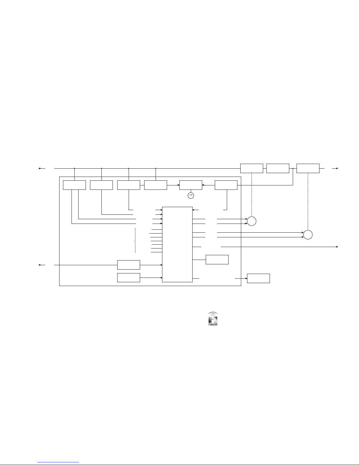
ATU-HP Technical Instruction Manual Page 6-3 (Page 6-4 Blank)
Section 6 Theory of Operation Issue 2.0
Figure 6-1 – Block Diagram of ATU-HP Automatic Antenna Tuning Unit
B1950006 VB
ATU CONTROL/
MONITOR PWB
A1
AC INPUT
SERVO RESPONSE
AND
MICROPROCESSOR
CIRCUITS
REGULATORS
VOLTAGE
TEMPERATURE
SENSOR
CONTROLS
PUSH BUTTON
XMTR ON/OFF
TUNE SETUP
INHIBIT MATCH
INHIBIT TUNE
INC/DEC R
INC/DEC L
AC INPUT
FROM XMTR RF INPUT
50
Ω
CURRENT PROBEPROBE
SERVO
AUTO DECREASE
AUTO INCREASE
50 CURRENT SAMPLE
Ω
Ω
50 VOLTAGE SAMPLE
LOCAL/REMOTE
Ω
50
VOLTAGE PROBE
FWD/REFLD
POWER PROBE
METER
SWITCHES
METER SELECTION
DECREASE R
INCREASE R
ANTENNA CURRENT SAMPLE
ANTENNA
CURRENT PROBE
MATCHING (R)
NETWORK
VARIABLE
TRANSFORMER
MATCHING
R
MOTOR
TUNING
RF OUT TO ANTENNA
NETWORK
INDUCTANCE (L)
VARIABLE
INCREASE L
RS-485 SERIAL LINK
DECREASE L
FAN ENABLE (TEMPERATURE DEPENDENT)
COOLING FANS
TO XMTR
SYSTEM STATUS &
TUNING LEDS
L
TUNING
MOTOR

6.3 DETAILED CIRCUIT
DESCRIPTIONS
The following descriptions are intended to
provide an in-depth understanding of
complex or non-obvious circuit functions.
The descriptions are keyed to the block
diagram in Figure 6-1 and expand on the
associated descriptions. Partial reference
designations are given in the following
descriptions. Refer to electrical schematics
Figures SD-1, SD-2 and SD-3.
NOTE
Unless otherwise specified, all reference
designations in the following paragraphs are
part of ATU control/monitor PWB A1. Refer
to Figures SD-2 and SD-3.
6.3.1 Servo Probe
Transformer T4 transforms the 50 Ω RF
current passing through the primary winding
to the secondary windings. The RF current
passing through T4’s secondary is
transformed to the secondary windings of T5.
Since the 10-turn secondary windings of T5
are identical, the RF current flowing in each
will be in phase. Diode bridges
CR9/CR10/CR17/CR18 and
CR11/CR12/CR19/CR20 act as RF
switches. They are alternately switched on
and off, one by the RF current’s positive half
cycle and the other by the negative half
cycle. The 50 Ohm RF In voltage signal
(TB1-1) is applied to both diode bridges after
being phase-shifted 90° by capacitor C5.
6.3.1.1 If this voltage is exactly 90° out of
phase with the current flowing in the 10-turn
secondaries of transformer T5, the net dc
potential, at the output of both diode bridges
will be zero, since both will gate equal
portions of the negative and positive half
cycles. In this state the Inc_L and Dec_L
signals applied to microcontroller U8 will be
low.
6.3.1.2 If the voltage from C5 is not exactly
90°out of phase with the current flowing in
the 10-turn secondaries of transformer T1,
the net dc output will be positive from one
diode bridge and negative from the other.
6.3.1.3 If the output of diode bridge
CR9/CR10/CR17/CR18 goes positive, a
high Inc_L signal and a low Dec_L signal
will be applied to microcontroller U8.
6.3.1.4 If the output of diode bridge
CR11/CR12/CR19/CR20 goes positive, a
high Dec_L signal and a low signal Inc_L
will be applied to microcontroller U8.
6.3.2 Forward/Reflected Power
Probe
Voltage transformer T6 and current
transformer T3 provide voltage and current
arms of a forward/reflected power bridge that
samples the RF output. The anti-phase
voltages across the secondaries of T3 are
summed with the voltage from T6 to provide
voltages at the anode of diodes CR29 and
CR31 that are proportional to the forward
and reflected power. Jumpers A (reflected)
and B (forward) are connected to read either
the high or low power scale of meter M1.
FWD/REFLD switch S10 selects the
parameter for display on meter M1.
CURRENT/RF POWER switch S11 must be
set to RF POWER to measure either FWD or
REFLD power. Potentiometer R70 provides
a means of calibrating the PWB meter.
6.3.3 Power Supplies
Ac power transformer T7, rectifier diodes
CR57 and CR58, and capacitor C73 provide
a full-wave rectified capacitive filtered dc
supply. Connections to TB2 and links
installed on TB3-1 through TB3-4 allow for
different ac supply voltages (115 V ac, 230 V
ac single-phase and 230 V ac split phase).
Fuses F1 and F2 protect T7 from excessive
current draw. Fuse F1 is only in circuit if a
split phase supply is used (230 V ac 60 Hz).
T7 provides a secondary voltage of 30 V ac
centre tapped. Diodes CR57/CR58 and
capacitor C73 rectify and filter the secondary
voltage. This unregulated dc supply level
(maximum 21.2 V dc at nominal mains) is
used to power the ATU cooling fans and to
generate +12 V dc for the motor drive
circuitry and motor supply.
ATU-HP Technical Instruction Manual Page 6-5
Section 6 Theory of Operation Issue 2.0

6.3.3.1 Regulator U5 and associated
components produce a +12 V dc supply
(+12V-A) from the unregulated fan supply.
This supply is used to power the inductive
tuning motor and drive circuitry. Regulator
U6 and associated components produce a
+12 V dc supply (+12 V-B) from the
unregulated fan supply. This supply is used
to power the resistive matcher tuning motor
and drive circuitry.
6.3.3.2 Both +12 V dc supplies are ORed
together through diodes CR35 and CR36
and applied to regulator U9 and associated
components to produce a +5 V dc supply.
The +5 V dc supply is used to power the
microcontroller and control circuitry.
6.3.4 Current/Voltage Samples
Current transformer T2 and resistors R28,
R42, R38, and R47 provide a sample of the
50 ohm RF input’s current. Diode CR32,
voltage divider R56 and R49 and RF filter
components R57, C19 and C21 provide a dc
voltage (Current_Sample), proportional to
the 50 ohm RF current sample, to the
microcontroller. A sample of the 50 ohm RF
voltage (Voltage_Sample) is applied to the
microcontroller through components CR30,
voltage divider R46 and R50, and RF filter
R55, C18 and C20. If the impedance at the
ATU’s RF input is 50 ohms, the
Current_Sample and Voltage_Sample
voltages will be equal. If the input impedance
is less than 50 ohms, the Current_ Sample
voltage will be higher. If the input impedance
is greater than 50 ohms the Voltage_Sample
voltage will be higher.
6.3.5 Antenna Current Probe
The RF current flowing into the ATU-HP’s
tuning coils also flows through the primary
winding of transformer T1. The current
transformed to T1’s secondary winding
flows through resistors R23/R24, diodes
CR13/CR14 and resistors through R25/R26,
diodes CR16/CR15 on alternate half cycles.
The voltage at the cathode junction of
diodes CR13/CR14, representative of the
antenna current, is applied to front panel
meter M1 via selectable resistors to allow for
Page 6-6 ATU-HP Technical Instruction Manual
Issue 2.0 Section 6 Theory of Operation
high or low current scale reading on the
meter. To read antenna current, RF
POWER/CURRENT switch S11 must be set
to CURRENT. A sample of the antenna
current (Ant_Current_Sample) is applied to
the microcontroller, via ANT CUR SAMPLE
potentiometer R51, through the RF filter
comprised of R71, C22 and C23.
6.3.6 Microcontroller Control
Microcontroller U8 receives analog, digital
and serial inputs and provides digital and
serial outputs. The microcontroller and its
associated components control the
operation of the ATU-HP’s cooling fans,
tuning motors, local and remote controls.
The microcontroller also generates the
ATU-HP’s alarms and status indications.
6.3.6.1 Analog Inputs
Microcontroller U8 accepts six analog
inputs: Voltage_Sample, Current_Sample,
Ant_Current Sample, Inc_L, Dec_L, and
Temp Sensor. All analog inputs have
conditioning circuitry consisting of two
diodes, to protect against excessive
voltages on the microcontroller as well as a
low pass R-C filter.
6.3.6.1.1 The Inc_L and Dec_L samples
are provided by the servo probe circuitry
(see paragraph 6.3.1). These samples are
used to determine whether more or less
inductance is needed to match the
capacitance of the antenna. U8 will control
the digital outputs which activate the motor
and associated LED indication (INCREASE
L, NORMAL L or DECREASE L) for the
loading coil accordingly.
6.3.6.1.2 The Voltage_Sample and
Current_ Sample inputs are provided by the
50 ohm current probe and the forward
reflected probe voltage transformer (see
paragraph 6.3.4). These samples are used
to determine whether the input resistance is
greater or less than the required 50 Ω. U8
will control the digital outputs which activate
the motor and associated LED indication
(INCREASE R, NORMAL R or DECREASE
R) for the resistive matcher accordingly.

6.3.6.1.3 The Ant_Current_Sample is
provided by the antenna current probe (see
paragraph 6.3.5). This sample is applied to
the associated transmitter, via serial
connection, and is used to cause automatic
power adjustments to keep the antenna
current constant.
6.3.6.1.4 The Temp Sensor input,
representative of the ATU-HP’s
temperature, is provided by the temperature
probe (U3 of temp probe PWB A5). If the
temperature exceeds 60°C, the
microcontroller will activate digital outputs
that turn on fans B2 and B3. This signal is
also applied to the associated transmitter
via serial connection.
6.3.6.2 Digital Inputs
8-bit shift registers U3 and U11 and their
associated components perform the
conditioning required to process digital
inputs. The digital inputs include nine pushbutton switches for ATU control/setup, four
limit switches to protect the two servos from
reaching their end limits and two inputs to
monitor the fan speed. A clock input is
applied to microcontroller U8 at pin 10.
When U8 pin 9 is cleared and then set, the
current digital inputs are loaded into U3 and
U11. Data is shifted from U3-9 to U11-10,
and then from U11-9 to U8-11. All switch
inputs are momentary.
6.3.6.2.1 The nine switches that affect data
sent to the microcontroller are: INCREASE
R (S5), DECREASE R (S6), INCREASE L
(S1), DECREASE L (S2), INHIBIT R
TUNING (S7), INHIBIT L TUNING (S3),
XMTR ON/OFF (S8), LOCAL/REMOTE
(S4) and TUNE SETUP (S9). Only the
LOCAL/REMOTE switch will operate if the
ATU-HP is in remote mode.
6.3.6.2.2 The INCREASE R, and
DECREASE R switches control the resistive
matcher movement and when pressed
activate the resistive matcher motor and
inhibit the Voltage_Sample and
Current_Sample inputs from affecting the
resistive tuning.
6.3.6.2.3 The INCREASE L and
DECREASE L switches control the
inductive motor movement and activate the
inductive tuning motor and inhibit the Inc_L
and Dec_L microcontroller inputs from
affecting the inductive tuning.
6.3.6.2.4 INHIBIT R TUNING and INHIBIT
L TUNING switches disable the ATU-HP
from auto tuning. Once the switch is
pressed the auto tune (for whichever motor
is inhibited) will not function until the switch
is pressed again.
6.3.6.2.5 LOCAL/REMOTE switch toggles
from local to remote mode. In remote mode
all other switches are inactive.
6.3.6.2.6 XMTR ON/OFF enables the user
to control a Vector series DGPS or NDB
transmitter from the ATU. The
microcontroller applies on/off commands to
the transmitter via serial connection.
6.3.6.2.7 The TUNE SETUP switch is used
during initial ATU-HP tuning when the
resistive matcher is not yet in circuit. Since
the resistive matcher (1/4-wave
transformer) is not in circuit, the Inc_L and
Dec_L signals are read in reverse by the
microcontroller while in TUNE SETUP
mode. For example: If Inc_L is high, the
DECREASE L status LED will be on and
the inductive motor will turn correctly.
6.3.6.2.8 Four limit inputs (R Limit Max, R
Limit Min, L Limit Max and L Limit Min)
instruct the microcontroller if a tuning limit
has been reached and, regardless of tuning
signals or local switch settings, the motor will
not travel beyond the limit.
6.3.6.2.9 Two digital inputs (Fan 1 Count
and Fan 2 Count) monitor fan rotation. With
each rotation of cooling fan B2’s (fan 1)
blade, the falling edge of the pulse at U8-32
will trigger an interrupt, effectively counting
the rotations. Resistor R114 and capacitor
C50 low-pass filter the input. Similarly, with
each rotation of cooling fan B3’s (fan 2)
blade, the falling edge of the pulse at U8-1
will trigger an interrupt, effectively counting
the rotations. Resistor R116 and capacitor
C51 low-pass filter the input.
ATU-HP Technical Instruction Manual Page 6-7
Section 6 Theory of Operation Issue 2.0

6.3.6.3 Digital Outputs
8-bit shift registers U1, U2, U4, and their
associated components perform the
conditioning required to produce digital
outputs. The digital outputs consist of 17
status/alarm LEDs, four motor control
outputs and two fan control outputs. These
outputs are shifted out of U8, using its SPI
bus, into U1, U2, and U4. U8 pin 26 is used
to latch the current values to U1, U2, and
U4.
6.3.6.3.1 Status/alarm LEDs include INHB
L TUNING (DS10), INHB R TUNING
(DS17), LOCAL (DS1), TUNE SETUP
(DS3), INCREASE R (DS13), DECREASE
R (DS15), NORMAL R (DS14), INCREASE
L (DS6), DECREASE L (DS8), NORMAL L
(DS7), FAN FAIL 1 (DS19), FAN FAIL 2
(DS21), R MAX LIMIT (DS12), R MIN LIMIT
(DS16), L MAX LIMIT (DS5), L MIN LIMIT
(DS9) and XMTR OFF (DS2).
6.3.6.3.2 Transistors Q14, Q15 and
associated components control the operation
of fan 1 (B2). When U4-2 switches high, Q14
turns on, Q15 turns on and the +V_Fan
voltage is applied to the Fan Control 1
output, causing the fan to turn on. When
U4-2 switches low, Q14 turns off, Q15 turns
off and the +V_Fan voltage is not applied to
the Fan Control 1 output, causing the fan to
turn off.
6.3.6.3.3 Transistors Q13, Q16 and
associated components control the operation
of fan 2 (B3). When U4-1 switches high, Q13
turns on, Q16 turns on and the +V_Fan
voltage is applied to the Fan Control 2
output, causing the fan to turn on. When
U4-1 switches low, Q13 turns off, Q16 turns
off and the +V_Fan voltage is not applied to
the Fan Control 2 output, causing the fan to
turn off.
6.3.6.3.4 If the fans have been enabled by
the microcontroller, the Fan 1 Count and
Fan 2 Count inputs (see paragraph
6.3.6.2.8) are active. If the fan count ceases
for longer than ten seconds, a FAN FAIL
(1
or 2) alarm will be generated and the fan
(B2 or B3) will be turned off by the
microcontroller.
6.3.6.3.5 Transistors Q1 through Q12 and
associated components form four identical
circuits that control the inductive and
resistive tune motors. For simplicity, only
the inductive tune motor’s control circuitry
will be described.
6.3.6.3.6 During tuned conditions, the
microcontroller applies low Inc_L_Servo
and Dec_L_Servo outputs to the base of
Q12 and Q11, causing the transistors to
turn off. Q8 and Q7 will turn on, causing Q4
and Q3 to turn on. Since the same potential
(+12 V) is being applied to the INCREASE
L (TB1-9) and DECREASE L (TB1-10)
outputs, current will not flow through
inductive tune motor B1.
6.3.6.3.7 If the Inc_L microcontroller input
from the servo probe is higher than the
Dec_L input, the microcontroller will
generate a high Inc_L_Servo output and
turn on the INCREASE L LED. Q12 turns
on. Q8 turns off, which causes Q4 to turn
off. A ground potential is applied, via Q12,
to the INCREASE L (TB1-9) output.
Inductive tune motor B1 will be active and
cause an increase in the loading coil
inductance.
6.3.6.3.8 If the Dec_L microcontroller input
from the servo probe is higher than the
Inc_L input, the microcontroller will generate
a high Dec_L_Servo output and turn on the
DECREASE L LED. Q11 turns on. Q8 turns
off, which causes Q3 to turn off. A ground
potential is applied, via Q11, to the
DECREASE L (TB1-10) output. Inductive
tune motor B1 will be active and cause a
decrease in the loading coil inductance.
6.3.6.3.9 If either of the L Limit Max or L
Limit Min inputs are active (high), then the
appropriate Inc_L_Servo or Dec_L_Servo
outputs will be held low (disabled) by the
microcontroller.
6.3.6.3.10 Motor control for the resistive
tune motor (A2B1) is similar to the
descriptions in paragraphs 6.3.6.3.6 through
6.3.6.3.9.
Page 6-8 ATU-HP Technical Instruction Manual
Issue 2.0 Section 6 Theory of Operation

6.3.7 Serial Communications
(RS485)
Microcontroller U8, ICs U12 through U15
and their associated components form the
serial communications circuit. U12 and U13
are opto-isolators used to provide isolation
between the ATU-HP and the associated
transmitter. U14 translates the TTL outputs
from U12 and U13 to balanced RS485. U15
(isolated dc-dc converter) supplies power to
the isolated circuit.
6.3.8 Motor Limit Control
See Figure SD-1. The motor limit control
circuitry consists of photo-interrupter
devices A4U1, A4U2 (for inductive tuning),
A2A1U1 and A2A1U2 (for resistive tuning)
and their associated components.
For inductive tuning, a mechanical travel
indicator, located on the inner coil shaft,
interrupts A4U1’s operation if the inner coil
is at its minimum inductance and interrupts
A4U2’s operation if the inner coil is at its
maximum inductance. For a minimum limit,
an open circuit will be present on J1-6 of the
limit switch PWB (A4). This removes the
ground normally applied to the ATU control/
monitor PWB’s L Limit Min input (A1J2-7).
For a maximum limit, an open circuit will be
present on J1-11 of the limit switch PWB
(A4). This removes the ground normally
applied to the ATU control/monitor PWB’s L
Limit Max input (A1J2-8).
For resistive tuning, a mechanical travel
indicator, located on the inner coil of the
resistive matcher, interrupts A2A1U1’s
operation if the resistive matcher is at
maximum and interrupts A2A1U2’s
operation if the resistive matcher is at
minimum. For a maximum limit, an open
circuit will be present on J1-13 of the
variable matching transformer assembly’s
limit switch PWB (A2A1). This removes the
ground normally applied to the ATU control/
monitor PWB’s R Limit Max input
(A1A1J2-5). For a minimum limit, an open
circuit will be present on J1-1 of the variable
matching transformer assembly’s limit
switch PWB (A2A1). This removes the
ground normally applied to the ATU control/
monitor PWB’s R Limit Min input (A1J2-6).
ATU-HP Technical Instruction Manual Page 6-9
Section 6 Theory of Operation Issue 2.0


ATU-HP
TECHNICAL INSTRUCTION MANUAL
Section 7 PARTS INFORMATION
7.1 INTRODUCTION
This section contains parts lists that provide
descriptive and provisioning information for all
electrical and mechanical parts that have
been assigned a reference designation and
form a part of the subject equipment.
7.2 REFERENCE DESIGNATION
LISTS
Individual reference designation lists are
provided for:
• assemblies that are assigned an alpha-
prefixed Nautel nomenclature (e.g.,
NAPC144
• cable harnesses that are assigned a
numbered Nautel part (e.g., 195-9002)
• optional kits that are assigned a
numbered Nautel part (e.g., 195-9054)
The reference designation lists, which are
titled and presented in alphanumeric order,
are divided into columns to aid in locating
specific information.
7.3 COLUMN CONTENT
EXPLANATION
The following paragraphs provide an
explanation of the purpose and contents of
each column in the reference designation
lists.
7.3.1 Ref Des Column
The ‘ref des’ column contains the reference
designation for a specific part. These
designations are assigned in accordance with
the requirements of American National
Standard Specification ANSI Y32.16.
Reference designations are listed
alphanumerically in this column.
A/01)
7.3.2 Description Column
This column contains the name and
descriptive information for each part. The key
word or noun is presented first, followed by
the adjective identifiers. When the
description is 'See Family Tree for Assembly
Nomenclature', the associated part is subject
to its own reference designation list or is
contained in an optional kit’s list. If a family
tree is not provided in this section, assume
the latter to be true.
7.3.3 Nautel # Column
This column contains the Nautel part number
assigned to each part. This number is
Nautel's drawing number for Nautel
manufactured parts, Nautel's configuration
control number for assemblies that are under
configuration control management or Nautel's
inventory management number for purchased
parts. When a Nautel configuration control
number (e.g. NAPC*) is referenced in this
column, the associated ref des item is subject
to its own reference designation table.
7.3.4 Vendor # Column
This column contains an original equipment
manufacturer's part number for a part. A
single part number is listed for each part,
even if there is more than one known
manufacturer. The listed number is Nautel's
usual or preferred choice. The use of this
number does not restrict Nautel from
selecting and using commercial equivalents,
where their use will not degrade circuit
operation or reliability, during manufacture.
ATU-HP Technical Instruction Manual Page 7-1
Section 7 Parts Information Issue 2.0

7.3.5 OEM Code Column
This column typically contains a five digit
coded group as the original equipment
manufacturer's (OEM) identifier. The code
was extracted from Cataloging Handbook
H4/H8 - Commercial and Government Entity
(Cage) Code. Manufacturers that were not
listed in the catalog when this listing was
compiled have been assigned a unique fiveletter code. This code is assigned arbitrarily
and has no other significance. The
manufacturers identified for parts that have
JAN or MIL part numbers are Nautel's
normal supply source for that part.
NOTE
OEM code 37338 is listed for parts
manufactured by Nautel or to a Nautel
control drawing. United States of America
customers should refer all replacement part
orders to Nautel Incorporated (OEM code
57655).
7.4 OEM CODE TO
MANUFACTURER CROSSREFERENCE
The OEM (CAGE) codes listed in the
reference designation lists are
representative of the original equipment
manufacturers of those parts. To determine
a specific part’s manufacturer contact
information, enter the five-character OEM
(CAGE) code for that part in the following
website:
https://www.bpn.gov/bincs/begin_search.asp
Upon entering the OEM (CAGE) code
number, manufacturer pertinent information
(address, telephone number, fax number,
etc.) shall be displayed. Please contact
Nautel if a part cannot be obtained (see
also ON-LINE PART QUOTES in this
manual’s Warranty section).
7.4.1 Manufacturer’s Index
For users without internet access, Table 7-1
provides a cross-reference from the original
equipment manufacturer’s (OEM) codes to
the manufacturer’s name. The listing is
sorted alphanumerically by the OEM code.
7.5 COMMON ABBREVIATIONS/
ACRONYMS
The following abbreviations/acronyms may
appear in Description column:
SMT - Denotes item is designed to be
installed using Surface Mount
Technology.
MTA - Denotes item is a Mass Termination
Assembly connector.
SIP - Single In-line Package
DIP - Dual In-line Package
IDC - Denotes item is an Insulation
Displacement connector for ribbon
cable.
Page 7-2 ATU-HP Technical InstructionManual
Issue 2.0 Section 7 Parts Information

Table 7-1 Manufacturer’s Index
02660 Amphenol Corp Spectra-Strip/Ltd.
04713 Motorola Incorporated
09482 Amp of Canada Limited
1FN41 Atmel Corporation
1K126 C & D Technolo gies
1KK13 ITT Industries Incorporated
1MQ07 ZRG Incorporated
13150 Axsys Technologies Incorporated
14655 Cornell Dubilier Electronics
22421 Thomas and Betts Limited
23875 M-Tron Industries Incorporated
24355 Analog Devices Inc.
27014 National Semiconductor Corp
31433 Kemet Electronics Corporation
37338 Nautel Limited
45496 Digital Systems
5Y407 Phoenix Contact Incorporated
50434 Agilent Technologies Incorporated
56289 Sprague Electric Company
56845 Vishay Dale Electronics Incorporated
57655 Nautel Main Incorporated
59124 KOA Speer Electronics Incorporated
62463 JTP Radiation Incorporated
63426 NKK Switches of America Incorporated
64155 Linear Technology Corporation
73831 Hammond Manufacturing Co. Ltd.
75042 TRW Incorporated
75915 Littelfuse Tracor Incorporated
80294 Bourns Instruments Incorporated
83330 Dialight Corporation, DBA Dialight
91833 Keystone Electronics Corporation
96095 AVX Ceramics Div of AVX Corporation
AGILENT See 50434
C & D See 1K126
KYCON See 22421
MORGAN Morgan Electro Ceramics
POLYVOLT Custom Products Corp.
VENKEL (3EQW4) Venkel Limited
ATU-HP Technical Instruction Manual Page 7-3
Section 7 Parts Information Issue 2.0


195-9002-01
REFDES NAUTEL #DESCRIPTION VENDOR # OEM CODE
P01 JT31Conn, IDC, D-Sub, P, HDE-20, 25-Pos 745496-3 09482
P02 JT30Conn, IDC, D-Sub, S, HDE-20, 25-Pos 745495-3 09482
P03 JT30Conn, IDC, D-Sub, S, HDE-20, 25-Pos 745495-3 09482
P04 JT31Conn, IDC, D-Sub, P, HDE-20, 25-Pos 745496-3 09482
ATU Cableform
195-9021-02
REFDES NAUTEL #DESCRIPTION VENDOR # OEM CODE
A01 195-9040Limit Switch PWB Assy 195-9040 37338
B01 ZAP28Motor, 12Vdc, Geared, 50 RPM CG-319A-50 POLY-VOL
195-9040
REFDES NAUTEL #DESCRIPTION VENDOR # OEM CODE
J01 JS12Conn, Plug, D-Sub, 25 pin, PWB Mt K22X-B25P-NJ 63590
U01 195-3051QI49 Verified 195-3051 37338
U02 195-3051QI49 Verified 195-3051 37338
195-9045
REFDES NAUTEL #DESCRIPTION VENDOR # OEM CODE
J01 JS12Conn, Plug, D-Sub, 25 pin, PWB Mt K22X-B25P-NJ 63590
U01 195-3051QI49 Verified 195-3051 37338
U02 195-3051QI49 Verified 195-3051 37338
ATU Variable Matching Transformer Assy (Standard band)
Limit Switch PWB Assy
Limit Switch PWB Assy
195-9050
REFDES NAUTEL #DESCRIPTION VENDOR # OEM CODE
TB01 JB33Terminal Block, 4-pos, Double, 30A 382100104 13150
TB02 JB33Terminal Block, 4-pos, Double, 30A 382100104 13150
Page 1 of 16
Matching Transformer Assy
195-9050

195-9089
Temperature Sensor PWB Assy
REFDES NAUTEL #DESCRIPTION VENDOR # OEM CODE
C08 CCP36Capacitor, Tantalum, Dipped, 10uF, 35V T351G106K035AT(Ro
HS) KEMET
C09 CCG07Capacitor, Ceramic, 0.1uF 10%100V CKR06BX104KRV 56289
C10 CCG07Capacitor, Ceramic, 0.1uF 10%100V CKR06BX104KRV 56289
J01 JS13Conn, Socket, D-Sub, 25 pin, PWB Mt K22-B25S-NJ 22421
R01 RAB25Resistor, MF, 1K Ohms, 1PC 1/4W MF1/4DL1001F 59124
R02 RAB25Resistor, MF, 1K Ohms, 1PC 1/4W MF1/4DL1001F 59124
R03 RAB37Resistor, MF, 10.0K Ohms, 1P C1/4W MF1/4DL1002F 59124
U03 UC58IC,Low Voltage Temp Sensor,+/-3 Deg,TO-92 TMP36GT9(STATIC) 45496
96095
Page 2 of 16
195-9089

NAPC144A/00
ATU Control/Monitor PWB Assy
REFDES NAUTEL #DESCRIPTION VENDOR # OEM CODE
C01 CCFS09Cap,SMT,Ceramic,0.47uF,10%,25V,X7R,0805 C0805C474K3RAC 31433
C02 CCFS09Cap,SMT,Ceramic,0.47uF,10%,25V,X7R,0805 C0805C474K3RAC 31433
C03 CCFS09Cap,SMT,Ceramic,0.47uF,10%,25V,X7R,0805 C0805C474K3RAC 31433
C04 CCFS09Cap,SMT,Ceramic,0.47uF,10%,25V,X7R,0805 C0805C474K3RAC 31433
C05 +Installed at Next Higher Assy INSTALLED AT NEXT
HIGHER ASSY
C06 CCFS07Cap,SMT,Ceramic,0.1uF,10%,50V,X7R,0805 C0805C104K5RAC 31433
C07 CCFS07Cap,SMT,Ceramic,0.1uF,10%,50V,X7R,0805 C0805C104K5RAC 31433
C08 CCFS07Cap,SMT,Ceramic,0.1uF,10%,50V,X7R,0805 C0805C104K5RAC 31433
C09 CCFS07Cap,SMT,Ceramic,0.1uF,10%,50V,X7R,0805 C0805C104K5RAC 31433
C10 CTFS03Cap,SMT,Tantalum,10uF,10%,35V,2917 T494D106K035AS 31433
C11 CTFS03Cap,SMT,Tantalum,10uF,10%,35V,2917 T494D106K035AS 31433
C12 CCFS07Cap,SMT,Ceramic,0.1uF,10%,50V,X7R,0805 C0805C104K5RAC 31433
C13 CCFS07Cap,SMT,Ceramic,0.1uF,10%,50V,X7R,0805 C0805C104K5RAC 31433
C14 CCFS07Cap,SMT,Ceramic,0.1uF,10%,50V,X7R,0805 C0805C104K5RAC 31433
C15 CCFS07Cap,SMT,Ceramic,0.1uF,10%,50V,X7R,0805 C0805C104K5RAC 31433
C16 CCFS07Cap,SMT,Ceramic,0.1uF,10%,50V,X7R,0805 C0805C104K5RAC 31433
C17 CCFS07Cap,SMT,Ceramic,0.1uF,10%,50V,X7R,0805 C0805C104K5RAC 31433
C18 CTFS03Cap,SMT,Tantalum,10uF,10%,35V,2917 T494D106K035AS 31433
C19 CTFS03Cap,SMT,Tantalum,10uF,10%,35V,2917 T494D106K035AS 31433
C20 CCFS07Cap,SMT,Ceramic,0.1uF,10%,50V,X7R,0805 C0805C104K5RAC 31433
C21 CCFS07Cap,SMT,Ceramic,0.1uF,10%,50V,X7R,0805 C0805C104K5RAC 31433
C22 CTFS03Cap,SMT,Tantalum,10uF,10%,35V,2917 T494D106K035AS 31433
C23 CCFS07Cap,SMT,Ceramic,0.1uF,10%,50V,X7R,0805 C0805C104K5RAC 31433
C24 CCFS04Cap,SMT,Ceramic,0.01uF,10%,50V,X7R,0603 C0603C103K5RAC 31433
C25 CCFS07Cap,SMT,Ceramic,0.1uF,10%,50V,X7R,0805 C0805C104K5RAC 31433
C26 CCFS07Cap,SMT,Ceramic,0.1uF,10%,50V,X7R,0805 C0805C104K5RAC 31433
C27 CCFS07Cap,SMT,Ceramic,0.1uF,10%,50V,X7R,0805 C0805C104K5RAC 31433
C28 CCFS07Cap,SMT,Ceramic,0.1uF,10%,50V,X7R,0805 C0805C104K5RAC 31433
C29 CCFS04Cap,SMT,Ceramic,0.01uF,10%,50V,X7R,0603 C0603C103K5RAC 31433
C30 CCFS04Cap,SMT,Ceramic,0.01uF,10%,50V,X7R,0603 C0603C103K5RAC 31433
C31 CCFS04Cap,SMT,Ceramic,0.01uF,10%,50V,X7R,0603 C0603C103K5RAC 31433
C32 CCFS07Cap,SMT,Ceramic,0.1uF,10%,50V,X7R,0805 C0805C104K5RAC 31433
C33 CCFS07Cap,SMT,Ceramic,0.1uF,10%,50V,X7R,0805 C0805C104K5RAC 31433
C34 CCFS07Cap,SMT,Ceramic,0.1uF,10%,50V,X7R,0805 C0805C104K5RAC 31433
C35 CCFS07Cap,SMT,Ceramic,0.1uF,10%,50V,X7R,0805 C0805C104K5RAC 31433
C36 CTFS03Cap,SMT,Tantalum,10uF,10%,35V,2917 T494D106K035AS 31433
C37 CCFS07Cap,SMT,Ceramic,0.1uF,10%,50V,X7R,0805 C0805C104K5RAC 31433
C38 CTFS02Cap,SMT,Tantalum,1uF,10%,35V,1411 T494B105K035AS 31433
C39 CTFS03Cap,SMT,Tantalum,10uF,10%,35V,2917 T494D106K035AS 31433
37338
Page 3 of 16
NAPC144A/00

Continued from previous page
NAPC144A/00
ATU Control/Monitor PWB Assy
REFDES NAUTEL #DESCRIPTION VENDOR # OEM CODE
C40 CTFS02Cap,SMT,Tantalum,1uF,10%,35V,1411 T494B105K035AS 31433
C41 CCFS07Cap,SMT,Ceramic,0.1uF,10%,50V,X7R,0805 C0805C104K5RAC 31433
C42 CCFS04Cap,SMT,Ceramic,0.01uF,10%,50V,X7R,0603 C0603C103K5RAC 31433
C43 CCFS23Cap,SMT,Ceramic,18pF,2%,50V,C0G,0603 C0603C180G5GAC 31433
C44 CCFS23Cap,SMT,Ceramic,18pF,2%,50V,C0G,0603 C0603C180G5GAC 31433
C45 CCFS04Cap,SMT,Ceramic,0.01uF,10%,50V,X7R,0603 C0603C103K5RAC 31433
C46 CCFS04Cap,SMT,Ceramic,0.01uF,10%,50V,X7R,0603 C0603C103K5RAC 31433
C47 CCFS07Cap,SMT,Ceramic,0.1uF,10%,50V,X7R,0805 C0805C104K5RAC 31433
C48 CCFS07Cap,SMT,Ceramic,0.1uF,10%,50V,X7R,0805 C0805C104K5RAC 31433
C49 CCFS07Cap,SMT,Ceramic,0.1uF,10%,50V,X7R,0805 C0805C104K5RAC 31433
C50 CCFS07Cap,SMT,Ceramic,0.1uF,10%,50V,X7R,0805 C0805C104K5RAC 31433
C51 CCFS07Cap,SMT,Ceramic,0.1uF,10%,50V,X7R,0805 C0805C104K5RAC 31433
C52 CCFS07Cap,SMT,Ceramic,0.1uF,10%,50V,X7R,0805 C0805C104K5RAC 31433
C53 CCFS07Cap,SMT,Ceramic,0.1uF,10%,50V,X7R,0805 C0805C104K5RAC 31433
C54 CCFS07Cap,SMT,Ceramic,0.1uF,10%,50V,X7R,0805 C0805C104K5RAC 31433
C55 CCFS07Cap,SMT,Ceramic,0.1uF,10%,50V,X7R,0805 C0805C104K5RAC 31433
C56 CCFS07Cap,SMT,Ceramic,0.1uF,10%,50V,X7R,0805 C0805C104K5RAC 31433
C57 CTFS03Cap,SMT,Tantalum,10uF,10%,35V,2917 T494D106K035AS 31433
C58 CCFS04Cap,SMT,Ceramic,0.01uF,10%,50V,X7R,0603 C0603C103K5RAC 31433
C59 CCFS07Cap,SMT,Ceramic,0.1uF,10%,50V,X7R,0805 C0805C104K5RAC 31433
C60 CCFS07Cap,SMT,Ceramic,0.1uF,10%,50V,X7R,0805 C0805C104K5RAC 31433
C61 CTFS01Cap,SMT,Tantalum,10uF,10%,16V,1411 T494B106K016AS 31433
C62 CCFS04Cap,SMT,Ceramic,0.01uF,10%,50V,X7R,0603 C0603C103K5RAC 31433
C63 CCFS07Cap,SMT,Ceramic,0.1uF,10%,50V,X7R,0805 C0805C104K5RAC 31433
C64 CTFS02Cap,SMT,Tantalum,1uF,10%,35V,1411 T494B105K035AS 31433
C65 CCFS04Cap,SMT,Ceramic,0.01uF,10%,50V,X7R,0603 C0603C103K5RAC 31433
C66 CCFS04Cap,SMT,Ceramic,0.01uF,10%,50V,X7R,0603 C0603C103K5RAC 31433
C67 CTFS02Cap,SMT,Tantalum,1uF,10%,35V,1411 T494B105K035AS 31433
C68 CCFS07Cap,SMT,Ceramic,0.1uF,10%,50V,X7R,0805 C0805C104K5RAC 31433
C69 CCFS07Cap,SMT,Ceramic,0.1uF,10%,50V,X7R,0805 C0805C104K5RAC 31433
C70 CCFS07Cap,SMT,Ceramic,0.1uF,10%,50V,X7R,0805 C0805C104K5RAC 31433
C71 CCFS07Cap,SMT,Ceramic,0.1uF,10%,50V,X7R,0805 C0805C104K5RAC 31433
C72 CCFS07Cap,SMT,Ceramic,0.1uF,10%,50V,X7R,0805 C0805C104K5RAC 31433
C73 +Installed at Next Higher Assy INSTALLED AT NEXT
HIGHER ASSY
C74 CCFS04Cap,SMT,Ceramic,0.01uF,10%,50V,X7R,0603 C0603C103K5RAC 31433
C75 CTFS02Cap,SMT,Tantalum,1uF,10%,35V,1411 T494B105K035AS 31433
C76 CTFS02Cap,SMT,Tantalum,1uF,10%,35V,1411 T494B105K035AS 31433
C77 CCFS04Cap,SMT,Ceramic,0.01uF,10%,50V,X7R,0603 C0603C103K5RAC 31433
C78 CTFS02Cap,SMT,Tantalum,1uF,10%,35V,1411 T494B105K035AS 31433
37338
Page 4 of 16
NAPC144A/00

Continued from previous page
NAPC144A/00
ATU Control/Monitor PWB Assy
REFDES NAUTEL #DESCRIPTION VENDOR # OEM CODE
C79 CCFS07Cap,SMT,Ceramic,0.1uF,10%,50V,X7R,0805 C0805C104K5RAC 31433
C80 CTFS03Cap,SMT,Tantalum,10uF,10%,35V,2917 T494D106K035AS 31433
C81 +Installed at Next Higher Assy INSTALLED AT NEXT
HIGHER ASSY
C82 +Installed at Next Higher Assy INSTALLED AT NEXT
HIGHER ASSY
C83 CCFS07Cap,SMT,Ceramic,0.1uF,10%,50V,X7R,0805 C0805C104K5RAC 31433
C84 CCFS07Cap,SMT,Ceramic,0.1uF,10%,50V,X7R,0805 C0805C104K5RAC 31433
CR01 QM47Diode,SMT,Ultrafast,200V,1A,SMB MURS120T3 04713
CR02 QM47Diode,SMT,Ultrafast,200V,1A,SMB MURS120T3 04713
CR03 QM47Diode,SMT,Ultrafast,200V,1A,SMB MURS120T3 04713
CR04 QM47Diode,SMT,Ultrafast,200V,1A,SMB MURS120T3 04713
CR05 QDRS01Diode,SMT,Switching,250V,0.2A,SOD-323 BAS21HT1(STATIC) 04713
CR06 QDRS01Diode,SMT,Switching,250V,0.2A,SOD-323 BAS21HT1(STATIC) 04713
CR07 QDRS01Diode,SMT,Switching,250V,0.2A,SOD-323 BAS21HT1(STATIC) 04713
CR08 QDRS01Diode,SMT,Switching,250V,0.2A,SOD-323 BAS21HT1(STATIC) 04713
CR09 QM47Diode,SMT,Ultrafast,200V,1A,SMB MURS120T3 04713
CR10 QM47Diode,SMT,Ultrafast,200V,1A,SMB MURS120T3 04713
CR11 QM47Diode,SMT,Ultrafast,200V,1A,SMB MURS120T3 04713
CR12 QM47Diode,SMT,Ultrafast,200V,1A,SMB MURS120T3 04713
CR13 QM47Diode,SMT,Ultrafast,200V,1A,SMB MURS120T3 04713
CR14 QM47Diode,SMT,Ultrafast,200V,1A,SMB MURS120T3 04713
CR15 QM47Diode,SMT,Ultrafast,200V,1A,SMB MURS120T3 04713
CR16 QM47Diode,SMT,Ultrafast,200V,1A,SMB MURS120T3 04713
CR17 QM47Diode,SMT,Ultrafast,200V,1A,SMB MURS120T3 04713
CR18 QM47Diode,SMT,Ultrafast,200V,1A,SMB MURS120T3 04713
CR19 QM47Diode,SMT,Ultrafast,200V,1A,SMB MURS120T3 04713
CR20 QM47Diode,SMT,Ultrafast,200V,1A,SMB MURS120T3 04713
CR21 QM47Diode,SMT,Ultrafast,200V,1A,SMB MURS120T3 04713
CR22 QM47Diode,SMT,Ultrafast,200V,1A,SMB MURS120T3 04713
CR23 QM47Diode,SMT,Ultrafast,200V,1A,SMB MURS120T3 04713
CR24 QM47Diode,SMT,Ultrafast,200V,1A,SMB MURS120T3 04713
CR25 QM47Diode,SMT,Ultrafast,200V,1A,SMB MURS120T3 04713
CR26 QM47Diode,SMT,Ultrafast,200V,1A,SMB MURS120T3 04713
CR27 QM47Diode,SMT,Ultrafast,200V,1A,SMB MURS120T3 04713
CR28 QM47Diode,SMT,Ultrafast,200V,1A,SMB MURS120T3 04713
CR29 QK48Diode,Schottky,100V,0.1A,DO-35 BAT41(STATIC) U3040
CR30 QK48Diode,Schottky,100V,0.1A,DO-35 BAT41(STATIC) U3040
CR31 QK48Diode,Schottky,100V,0.1A,DO-35 BAT41(STATIC) U3040
CR32 QK48Diode,Schottky,100V,0.1A,DO-35 BAT41(STATIC) U3040
37338
37338
Page 5 of 16
NAPC144A/00

Continued from previous page
NAPC144A/00
ATU Control/Monitor PWB Assy
REFDES NAUTEL #DESCRIPTION VENDOR # OEM CODE
CR33 +Installed at Next Higher Assy INSTALLED AT NEXT
HIGHER ASSY
CR34 QM47Diode,SMT,Ultrafast,200V,1A,SMB MURS120T3 04713
CR35 QM47Diode,SMT,Ultrafast,200V,1A,SMB MURS120T3 04713
CR36 QM47Diode,SMT,Ultrafast,200V,1A,SMB MURS120T3 04713
CR37 QM47Diode,SMT,Ultrafast,200V,1A,SMB MURS120T3 04713
CR38 QDSS01Diode,SMT,Schottky,30V,0.2A,SOD-323 BAT54HT1(STATIC) 04713
CR39 QDSS01Diode,SMT,Schottky,30V,0.2A,SOD-323 BAT54HT1(STATIC) 04713
CR40 QDSS01Diode,SMT,Schottky,30V,0.2A,SOD-323 BAT54HT1(STATIC) 04713
CR41 QDSS01Diode,SMT,Schottky,30V,0.2A,SOD-323 BAT54HT1(STATIC) 04713
CR42 QDSS01Diode,SMT,Schottky,30V,0.2A,SOD-323 BAT54HT1(STATIC) 04713
CR43 QDSS01Diode,SMT,Schottky,30V,0.2A,SOD-323 BAT54HT1(STATIC) 04713
CR44 QDSS01Diode,SMT,Schottky,30V,0.2A,SOD-323 BAT54HT1(STATIC) 04713
CR45 QDSS01Diode,SMT,Schottky,30V,0.2A,SOD-323 BAT54HT1(STATIC) 04713
CR46 QDSS01Diode,SMT,Schottky,30V,0.2A,SOD-323 BAT54HT1(STATIC) 04713
CR47 QDSS01Diode,SMT,Schottky,30V,0.2A,SOD-323 BAT54HT1(STATIC) 04713
CR48 QDSS01Diode,SMT,Schottky,30V,0.2A,SOD-323 BAT54HT1(STATIC) 04713
CR49 -Not Used NOT USED 37338
CR50 -Not Used NOT USED 37338
CR51 QDSS01Diode,SMT,Schottky,30V,0.2A,SOD-323 BAT54HT1(STATIC) 04713
CR52 -Not Used NOT USED 37338
CR53 -Not Used NOT USED 37338
CR54 QM47Diode,SMT,Ultrafast,200V,1A,SMB MURS120T3 04713
CR55 QM47Diode,SMT,Ultrafast,200V,1A,SMB MURS120T3 04713
CR56 QM47Diode,SMT,Ultrafast,200V,1A,SMB MURS120T3 04713
CR57 QM47Diode,SMT,Ultrafast,200V,1A,SMB MURS120T3 04713
CR58 QM47Diode,SMT,Ultrafast,200V,1A,SMB MURS120T3 04713
CR59 QM47Diode,SMT,Ultrafast,200V,1A,SMB MURS120T3 04713
CR60 QM47Diode,SMT,Ultrafast,200V,1A,SMB MURS120T3 04713
CR61 +Installed at Next Higher Assy INSTALLED AT NEXT
HIGHER ASSY
DS01 QDLS07Diode, SMT, LED, Amber,(592nm), 0603 598-8040-
107F(STATIC)(RoHS)
DS02 QDLS03Diode, SMT, LED, Red, (660nm),0603 597-5112-
402(STATIC)
DS03 QDLS03Diode, SMT, LED, Red, (660nm),0603 597-5112-
402(STATIC)
DS04 QDLS01Diode, SMT, LED, Green,(560nm), 0603 597-5312-
402F(STATIC)(RoHS)
DS05 QDLS03Diode, SMT, LED, Red, (660nm),0603 597-5112-
402(STATIC)
DS06 QDLS07Diode, SMT, LED, Amber,(592nm), 0603 598-8040-
107F(STATIC)(RoHS)
37338
37338
83330
83330
83330
83330
83330
83330
Page 6 of 16
NAPC144A/00

Continued from previous page
NAPC144A/00
ATU Control/Monitor PWB Assy
REFDES NAUTEL #DESCRIPTION VENDOR # OEM CODE
DS07 QDLS01Diode, SMT, LED, Green,(560nm), 0603 597-5312-
402F(STATIC)(RoHS)
DS08 QDLS07Diode, SMT, LED, Amber,(592nm), 0603 598-8040-
107F(STATIC)(RoHS)
DS09 QDLS03Diode, SMT, LED, Red, (660nm),0603 597-5112-
402(STATIC)
DS10 QDLS03Diode, SMT, LED, Red, (660nm),0603 597-5112-
402(STATIC)
DS11 QDLS01Diode, SMT, LED, Green,(560nm), 0603 597-5312-
402F(STATIC)(RoHS)
DS12 QDLS03Diode, SMT, LED, Red, (660nm),0603 597-5112-
402(STATIC)
DS13 QDLS07Diode, SMT, LED, Amber,(592nm), 0603 598-8040-
107F(STATIC)(RoHS)
DS14 QDLS01Diode, SMT, LED, Green,(560nm), 0603 597-5312-
402F(STATIC)(RoHS)
DS15 QDLS07Diode, SMT, LED, Amber,(592nm), 0603 598-8040-
107F(STATIC)(RoHS)
DS16 QDLS03Diode, SMT, LED, Red, (660nm),0603 597-5112-
402(STATIC)
DS17 QDLS03Diode, SMT, LED, Red, (660nm),0603 597-5112-
402(STATIC)
DS18 QDLS01Diode, SMT, LED, Green,(560nm), 0603 597-5312-
402F(STATIC)(RoHS)
DS19 QDLS03Diode, SMT, LED, Red, (660nm),0603 597-5112-
402(STATIC)
DS20 QDLS01Diode, SMT, LED, Green,(560nm), 0603 597-5312-
402F(STATIC)(RoHS)
DS21 QDLS03Diode, SMT, LED, Red, (660nm),0603 597-5112-
402(STATIC)
E01 HR08Terminal, PWB, 6-32, Vert 8191 91833
E02 HR08Terminal, PWB, 6-32, Vert 8191 91833
E03 HR08Terminal, PWB, 6-32, Vert 8191 91833
E04 HR08Terminal, PWB, 6-32, Vert 8191 91833
E05 HR08Terminal, PWB, 6-32, Vert 8191 91833
E06 HR08Terminal, PWB, 6-32, Vert 8191 91833
F01 +Installed at Next Higher Assy INSTALLED AT NEXT
HIGHER ASSY
F02 +Installed at Next Higher Assy INSTALLED AT NEXT
HIGHER ASSY
J01 JF47Conn, Header,Square Post,Gold,Dual,40-pin 4-102973-0 09482
J02 JS13Conn, Socket, D-Sub, 25 pin, PWB Mt K22-B25S-NJ 22421
J03 JQ34Conn, Socket, D-Sub, 9 pin, PWB Mt K22-E9S-NJ KYCON
L01 LCFS01Inductor, SMT, Choke, 600ohms,2A, 0805 ILHB0805RK601V 56845
L02 LCFS01Inductor, SMT, Choke, 600ohms,2A, 0805 ILHB0805RK601V 56845
L03 LCFS01Inductor, SMT, Choke, 600ohms,2A, 0805 ILHB0805RK601V 56845
L04 LCFS01Inductor, SMT, Choke, 600ohms,2A, 0805 ILHB0805RK601V 56845
L05 LCFS01Inductor, SMT, Choke, 600ohms,2A, 0805 ILHB0805RK601V 56845
83330
83330
83330
83330
83330
83330
83330
83330
83330
83330
83330
83330
83330
83330
83330
37338
37338
Page 7 of 16
NAPC144A/00

Continued from previous page
NAPC144A/00
ATU Control/Monitor PWB Assy
REFDES NAUTEL #DESCRIPTION VENDOR # OEM CODE
L06 LCFS01Inductor, SMT, Choke, 600ohms,2A, 0805 ILHB0805RK601V 56845
L07 LCFS01Inductor, SMT, Choke, 600ohms,2A, 0805 ILHB0805RK601V 56845
L08 +Installed at Next Higher Assy INSTALLED AT NEXT
HIGHER ASSY
M01 +Installed at Next Higher Assy INSTALLED AT NEXT
HIGHER ASSY
Q01 QN51Transistor, PNP, Darlington,8A TIP107(STATIC) 1MQ07
Q02 QN51Transistor, PNP, Darlington,8A TIP107(STATIC) 1MQ07
Q03 QN51Transistor, PNP, Darlington,8A TIP107(STATIC) 1MQ07
Q04 QN51Transistor, PNP, Darlington,8A TIP107(STATIC) 1MQ07
Q05 QBNS01Transistor,SMT,NPN,Switch/Amp,SOT-23 MMBT4401LT1(STATI
C)
Q06 QBNS01Transistor,SMT,NPN,Switch/Amp,SOT-23 MMBT4401LT1(STATI
C)
Q07 QBNS01Transistor,SMT,NPN,Switch/Amp,SOT-23 MMBT4401LT1(STATI
C)
Q08 QBNS01Transistor,SMT,NPN,Switch/Amp,SOT-23 MMBT4401LT1(STATI
C)
Q09 QM34Transistor, NPN, Darlington, Plastic TIP102(STATIC) 04713
Q10 QM34Transistor, NPN, Darlington, Plastic TIP102(STATIC) 04713
Q11 QM34Transistor, NPN, Darlington, Plastic TIP102(STATIC) 04713
Q12 QM34Transistor, NPN, Darlington, Plastic TIP102(STATIC) 04713
Q13 QBNS01Transistor,SMT,NPN,Switch/Amp,SOT-23 MMBT4401LT1(STATI
C)
Q14 QBNS01Transistor,SMT,NPN,Switch/Amp,SOT-23 MMBT4401LT1(STATI
C)
Q15 QBPS01Transistor,SMT,PNP,Switch/Amp,SOT-23 MMBT4403LT1(STATI
C)
Q16 QBPS01Transistor,SMT,PNP,Switch/Amp,SOT-23 MMBT4403LT1(STATI
C)
Q17 +Installed at Next Higher Assy INSTALLED AT NEXT
HIGHER ASSY
R001 RFFS43Resistor,SMT,MF,2740ohms,1%,1/10W,0603 RK73H1JLTD2741F 59124
R002 RFFS43Resistor,SMT,MF,2740ohms,1%,1/10W,0603 RK73H1JLTD2741F 59124
R003 RFFS43Resistor,SMT,MF,2740ohms,1%,1/10W,0603 RK73H1JLTD2741F 59124
R004 RFFS43Resistor,SMT,MF,2740ohms,1%,1/10W,0603 RK73H1JLTD2741F 59124
R005 RFFS43Resistor,SMT,MF,2740ohms,1%,1/10W,0603 RK73H1JLTD2741F 59124
R006 RFFS43Resistor,SMT,MF,2740ohms,1%,1/10W,0603 RK73H1JLTD2741F 59124
R007 RFFS43Resistor,SMT,MF,2740ohms,1%,1/10W,0603 RK73H1JLTD2741F 59124
R008 RFFS43Resistor,SMT,MF,2740ohms,1%,1/10W,0603 RK73H1JLTD2741F 59124
R009 RFFS34Resistor,SMT,MF,475ohms,1%,1/10W,0603 RK73H1JLTD475 0F 59124
R010 RFFS41Resistor,SMT,MF,1820ohms,1%,1/10W,0603 RK73H1JLTD1821F 59124
R011 RFFS50Resistor,SMT,MF,10.0Kohms,1%,1/10W,0603 RK73H1JLTD1002F 59124
R012 RFFS41Resistor,SMT,MF,1820ohms,1%,1/10W,0603 RK73H1JLTD1821F 59124
R013 RFFS41Resistor,SMT,MF,1820ohms,1%,1/10W,0603 RK73H1JLTD1821F 59124
37338
37338
04713
04713
04713
04713
04713
04713
04713
04713
37338
Page 8 of 16
NAPC144A/00

Continued from previous page
NAPC144A/00
ATU Control/Monitor PWB Assy
REFDES NAUTEL #DESCRIPTION VENDOR # OEM CODE
R014 RFFS50Resistor,SMT,MF,10.0Kohms,1%,1/10W,0603 RK73H1JLTD1002F 59124
R015 RFFS41Resistor,SMT,MF,1820ohms,1%,1/10W,0603 RK73H1JLTD1821F 59124
R016 RFFS41Resistor,SMT,MF,1820ohms,1%,1/10W,0603 RK73H1JLTD1821F 59124
R017 RFFS50Resistor,SMT,MF,10.0Kohms,1%,1/10W,0603 RK73H1JLTD1002F 59124
R018 RFFS41Resistor,SMT,MF,1820ohms,1%,1/10W,0603 RK73H1JLTD1821F 59124
R019 RFFS41Resistor,SMT,MF,1820ohms,1%,1/10W,0603 RK73H1JLTD1821F 59124
R020 RFFS50Resistor,SMT,MF,10.0Kohms,1%,1/10W,0603 RK73H1JLTD1002F 59124
R021 RFFS41Resistor,SMT,MF,1820ohms,1%,1/10W,0603 RK73H1JLTD1821F 59124
R022 RBP13Resistor, Film, 1000 Ohms, 5%, 2W GS-3, 1000 OHMS 75042
R023 RBP02Resistor, Film, 15 Ohms, 5% 2W GS-3, 15 OHMS 75042
R024 RBP02Resistor, Film, 15 Ohms, 5% 2W GS-3, 15 OHMS 75042
R025 RBP02Resistor, Film, 15 Ohms, 5% 2W GS-3, 15 OHMS 75042
R026 RBP02Resistor, Film, 15 Ohms, 5% 2W GS-3, 15 OHMS 75042
R027 RBP13Resistor, Film, 1000 Ohms, 5%, 2W GS-3, 1000 OHMS 75042
R028 RBP07Resistor, Film, 100 Ohms, 5%2W GS-3, 100 OHMS 75042
R029 RFFS38Resistor,SMT,MF,1000ohms,1%,1/10W,0603 RK73H1JLTD1001F 59124
R030 RFFS38Resistor,SMT,MF,1000ohms,1%,1/10W,0603 RK73H1JLTD1001F 59124
R031 RFFS38Resistor,SMT,MF,1000ohms,1%,1/10W,0603 RK73H1JLTD1001F 59124
R032 RFFS38Resistor,SMT,MF,1000ohms,1%,1/10W,0603 RK73H1JLTD1001F 59124
R033 RBP13Resistor, Film, 1000 Ohms, 5%, 2W GS-3, 1000 OHMS 75042
R034 +Installed at Next Higher Assy INSTALLED AT NEXT
HIGHER ASSY
R035 +Installed at Next Higher Assy INSTALLED AT NEXT
HIGHER ASSY
R036 RFFS38Resistor,SMT,MF,1000ohms,1%,1/10W,0603 RK73H1JLTD1001F 59124
R037 RFFS50Resistor,SMT,MF,10.0Kohms,1%,1/10W,0603 RK73H1JLTD1002F 59124
R038 RBP07Resistor, Film, 100 Ohms, 5%2W GS-3, 100 OHMS 75042
R039 RFFS55Resistor,SMT,MF,27.4Kohms,1%,1/10W,0603 RK73H1JLTD2742F 59124
R040 RBP13Resistor, Film, 1000 Ohms, 5%, 2W GS-3, 1000 OHMS 75042
R041 +Installed at Next Higher Assy INSTALLED AT NEXT
HIGHER ASSY
R042 RBP07Resistor, Film, 100 Ohms, 5%2W GS-3, 100 OHMS 75042
R043 +Installed at Next Higher Assy INSTALLED AT NEXT
HIGHER ASSY
R044 +Installed at Next Higher Assy INSTALLED AT NEXT
HIGHER ASSY
R045 RBP13Resistor, Film, 1000 Ohms, 5%, 2W GS-3, 1000 OHMS 75042
R046 RFFS52Resistor,SMT,MF,15.0Kohms,1%,1/10W,0603 RK73H1JLTD1502F 59124
R047 RBP07Resistor, Film, 100 Ohms, 5%2W GS-3, 100 OHMS 75042
R048 RFFS55Resistor,SMT,MF,27.4Kohms,1%,1/10W,0603 RK73H1JLTD2742F 59124
R049 RFFS50Resistor,SMT,MF,10.0Kohms,1%,1/10W,0603 RK73H1JLTD1002F 59124
R050 RFFS50Resistor,SMT,MF,10.0Kohms,1%,1/10W,0603 RK73H1JLTD1002F 59124
37338
37338
37338
37338
37338
Page 9 of 16
NAPC144A/00

Continued from previous page
NAPC144A/00
ATU Control/Monitor PWB Assy
REFDES NAUTEL #DESCRIPTION VENDOR # OEM CODE
R051 RW01Resistor, Variable, Film, 100K Ohms, 1/2W 3339P-1-104 80294
R052 +Installed at Next Higher Assy INSTALLED AT NEXT
HIGHER ASSY
R053 +Installed at Next Higher Assy INSTALLED AT NEXT
HIGHER ASSY
R054 +Installed at Next Higher Assy INSTALLED AT NEXT
HIGHER ASSY
R055 RFFS62Resistor,SMT,MF,100Kohms,1%,1/10W,0603 RK73H1JLTD1003F 59124
R056 RFFS52Resistor,SMT,MF,15.0Kohms,1%,1/10W,0603 RK73H1JLTD1502F 59124
R057 RFFS62Resistor,SMT,MF,100Kohms,1%,1/10W,0603 RK73H1JLTD1003F 59124
R058 RFFS52Resistor,SMT,MF,15.0Kohms,1%,1/10W,0603 RK73H1JLTD1502F 59124
R062 +Installed at Next Higher Assy INSTALLED AT NEXT
HIGHER ASSY
R063 +Installed at Next Higher Assy INSTALLED AT NEXT
HIGHER ASSY
R064 +Installed at Next Higher Assy INSTALLED AT NEXT
HIGHER ASSY
R066 RFFS38Resistor,SMT,MF,1000ohms,1%,1/10W,0603 RK73H1JLTD1001F 59124
R067 RFFS38Resistor,SMT,MF,1000ohms,1%,1/10W,0603 RK73H1JLTD1001F 59124
R068 RFFS38Resistor,SMT,MF,1000ohms,1%,1/10W,0603 RK73H1JLTD1001F 59124
R069 RFFS38Resistor,SMT,MF,1000ohms,1%,1/10W,0603 RK73H1JLTD1001F 59124
R070 RW36Resistor, Variable, Film, 500Ohms, 1/2W 3339P-1-501 80294
R071 RFFS62Resistor,SMT,MF,100Kohms,1%,1/10W,0603 RK73H1JLTD1003F 59124
R072 RFFS32Resistor,SMT,MF,332ohms,1%,1/10W,0603 RK73H1JLTD332 0F 59124
R073 RFFS38Resistor,SMT,MF,1000ohms,1%,1/10W,0603 RK73H1JLTD1001F 59124
R074 RFFS39Resistor,SMT,MF,1210ohms,1%,1/10W,0603 RK73H1JLTD1211F 59124
R076 RFFS50Resistor,SMT,MF,10.0Kohms,1%,1/10W,0603 RK73H1JLTD1002F 59124
R077 RFFS50Resistor,SMT,MF,10.0Kohms,1%,1/10W,0603 RK73H1JLTD1002F 59124
R078 RFFS50Resistor,SMT,MF,10.0Kohms,1%,1/10W,0603 RK73H1JLTD1002F 59124
R079 RFFS34Resistor,SMT,MF,475ohms,1%,1/10W,0603 RK73H1JLTD475 0F 59124
R080 RFFS50Resistor,SMT,MF,10.0Kohms,1%,1/10W,0603 RK73H1JLTD1002F 59124
R081 RFFS46Resistor,SMT,MF,4750ohms,1%,1/10W,0603 RK73H1JLTD4751F 59124
R083 RFFS38Resistor,SMT,MF,1000ohms,1%,1/10W,0603 RK73H1JLTD1001F 59124
R084 RFFS38Resistor,SMT,MF,1000ohms,1%,1/10W,0603 RK73H1JLTD1001F 59124
R085 RFFS38Resistor,SMT,MF,1000ohms,1%,1/10W,0603 RK73H1JLTD1001F 59124
R086 RFFS38Resistor,SMT,MF,1000ohms,1%,1/10W,0603 RK73H1JLTD1001F 59124
R087 RFFS50Resistor,SMT,MF,10.0Kohms,1%,1/10W,0603 RK73H1JLTD1002F 59124
R088 RFFS50Resistor,SMT,MF,10.0Kohms,1%,1/10W,0603 RK73H1JLTD1002F 59124
R089 RFFS50Resistor,SMT,MF,10.0Kohms,1%,1/10W,0603 RK73H1JLTD1002F 59124
R090 RFFS34Resistor,SMT,MF,475ohms,1%,1/10W,0603 RK73H1JLTD475 0F 59124
R091 RFFS50Resistor,SMT,MF,10.0Kohms,1%,1/10W,0603 RK73H1JLTD1002F 59124
R092 RFFS34Resistor,SMT,MF,475ohms,1%,1/10W,0603 RK73H1JLTD475 0F 59124
37338
37338
37338
37338
37338
37338
Page 10 of 16
NAPC144A/00

Continued from previous page
NAPC144A/00
ATU Control/Monitor PWB Assy
REFDES NAUTEL #DESCRIPTION VENDOR # OEM CODE
R093 RFFS34Resistor,SMT,MF,475ohms,1%,1/10W,0603 RK73H1JLTD475 0F 59124
R094 RFFS34Resistor,SMT,MF,475ohms,1%,1/10W,0603 RK73H1JLTD475 0F 59124
R095 RFFS34Resistor,SMT,MF,475ohms,1%,1/10W,0603 RK73H1JLTD475 0F 59124
R096 RFFS34Resistor,SMT,MF,475ohms,1%,1/10W,0603 RK73H1JLTD475 0F 59124
R097 RFFS34Resistor,SMT,MF,475ohms,1%,1/10W,0603 RK73H1JLTD475 0F 59124
R098 RFFS34Resistor,SMT,MF,475ohms,1%,1/10W,0603 RK73H1JLTD475 0F 59124
R099 RFFS34Resistor,SMT,MF,475ohms,1%,1/10W,0603 RK73H1JLTD475 0F 59124
R100 RFFS41Resistor,SMT,MF,1820ohms,1%,1/10W,0603 RK73H1JLTD1821F 59124
R101 RFFS41Resistor,SMT,MF,1820ohms,1%,1/10W,0603 RK73H1JLTD1821F 59124
R102 RFFS34Resistor,SMT,MF,475ohms,1%,1/10W,0603 RK73H1JLTD475 0F 59124
R103 RFFS34Resistor,SMT,MF,475ohms,1%,1/10W,0603 RK73H1JLTD475 0F 59124
R104 RFFS34Resistor,SMT,MF,475ohms,1%,1/10W,0603 RK73H1JLTD475 0F 59124
R105 RFFS34Resistor,SMT,MF,475ohms,1%,1/10W,0603 RK73H1JLTD475 0F 59124
R106 RFFS34Resistor,SMT,MF,475ohms,1%,1/10W,0603 RK73H1JLTD475 0F 59124
R107 RFFS34Resistor,SMT,MF,475ohms,1%,1/10W,0603 RK73H1JLTD475 0F 59124
R108 RFFS50Resistor,SMT,MF,10.0Kohms,1%,1/10W,0603 RK73H1JLTD1002F 59124
R109 RFFS50Resistor,SMT,MF,10.0Kohms,1%,1/10W,0603 RK73H1JLTD1002F 59124
R110 RFFS50Resistor,SMT,MF,10.0Kohms,1%,1/10W,0603 RK73H1JLTD1002F 59124
R111 RFFS50Resistor,SMT,MF,10.0Kohms,1%,1/10W,0603 RK73H1JLTD1002F 59124
R112 RFFS50Resistor,SMT,MF,10.0Kohms,1%,1/10W,0603 RK73H1JLTD1002F 59124
R113 RFFS50Resistor,SMT,MF,10.0Kohms,1%,1/10W,0603 RK73H1JLTD1002F 59124
R114 RFFS38Resistor,SMT,MF,1000ohms,1%,1/10W,0603 RK73H1JLTD1001F 59124
R115 RFFS50Resistor,SMT,MF,10.0Kohms,1%,1/10W,0603 RK73H1JLTD1002F 59124
R116 RFFS38Resistor,SMT,MF,1000ohms,1%,1/10W,0603 RK73H1JLTD1001F 59124
R117 RFFS50Resistor,SMT,MF,10.0Kohms,1%,1/10W,0603 RK73H1JLTD1002F 59124
R118 RFFS34Resistor,SMT,MF,475ohms,1%,1/10W,0603 RK73H1JLTD475 0F 59124
R119 RFFS34Resistor,SMT,MF,475ohms,1%,1/10W,0603 RK73H1JLTD475 0F 59124
R120 RFFS50Resistor,SMT,MF,10.0Kohms,1%,1/10W,0603 RK73H1JLTD1002F 59124
R121 RFFS38Resistor,SMT,MF,1000ohms,1%,1/10W,0603 RK73H1JLTD1001F 59124
R122 RFFS62Resistor,SMT,MF,100Kohms,1%,1/10W,0603 RK73H1JLTD1003F 59124
R123 RFFS34Resistor,SMT,MF,475ohms,1%,1/10W,0603 RK73H1JLTD475 0F 59124
R124 RFFS45Resistor,SMT,MF,3920ohms,1%,1/10W,0603 RK73H1JLTD3921F 59124
R125 RAD30Resistor, SMT, MF, 2740 Ohms,1% 1/4W RK73H2BL2741F 59124
R126 RFFS50Resistor,SMT,MF,10.0Kohms,1%,1/10W,0603 RK73H1JLTD1002F 59124
R127 RAD30Resistor, SMT, MF, 2740 Ohms,1% 1/4W RK73H2BL2741F 59124
R128 RFFS50Resistor,SMT,MF,10.0Kohms,1%,1/10W,0603 RK73H1JLTD1002F 59124
R129 RFFS45Resistor,SMT,MF,3920ohms,1%,1/10W,0603 RK73H1JLTD3921F 59124
R130 RFFS62Resistor,SMT,MF,100Kohms,1%,1/10W,0603 RK73H1JLTD1003F 59124
R131 RFFS42Resistor,SMT,MF,2210ohms,1%,1/10W,0603 RK73H1JLTD2211F 59124
Page 11 of 16
NAPC144A/00

Continued from previous page
NAPC144A/00
ATU Control/Monitor PWB Assy
REFDES NAUTEL #DESCRIPTION VENDOR # OEM CODE
R132 RFFS42Resistor,SMT,MF,2210ohms,1%,1/10W,0603 RK73H1JLTD2211F 59124
R133 RFFS38Resistor,SMT,MF,1000ohms,1%,1/10W,0603 RK73H1JLTD1001F 59124
R134 RFFS50Resistor,SMT,MF,10.0Kohms,1%,1/10W,0603 RK73H1JLTD1002F 59124
R135 RFFS50Resistor,SMT,MF,10.0Kohms,1%,1/10W,0603 RK73H1JLTD1002F 59124
R136 RFFS50Resistor,SMT,MF,10.0Kohms,1%,1/10W,0603 RK73H1JLTD1002F 59124
R137 RFFS50Resistor,SMT,MF,10.0Kohms,1%,1/10W,0603 RK73H1JLTD1002F 59124
R138 RFFS50Resistor,SMT,MF,10.0Kohms,1%,1/10W,0603 RK73H1JLTD1002F 59124
R139 RFFS50Resistor,SMT,MF,10.0Kohms,1%,1/10W,0603 RK73H1JLTD1002F 59124
R140 RFFS50Resistor,SMT,MF,10.0Kohms,1%,1/10W,0603 RK73H1JLTD1002F 59124
R141 RAD49Resistor,SMT,MF,10ohms,1%,2W CR2512-2W-10R0F VENKEL
R142 RAD27Resistor, SMT, MF, 1500 Ohms,1% 1/4W RK73H2BL1501F 59124
R143 RAD26Resistor, SMT, MF, 1210 Ohms,1% 1/4W RK73H2BL1211F 59124
R144 RAD27Resistor, SMT, MF, 1500 Ohms,1% 1/4W RK73H2BL1501F 59124
R145 RAD26Resistor, SMT, MF, 1210 Ohms,1% 1/4W RK73H2BL1211F 59124
R146 RFFS38Resistor,SMT,MF,1000ohms,1%,1/10W,0603 RK73H1JLTD1001F 59124
R147 RFFS42Resistor,SMT,MF,2210ohms,1%,1/10W,0603 RK73H1JLTD2211F 59124
R148 RFFS38Resistor,SMT,MF,1000ohms,1%,1/10W,0603 RK73H1JLTD1001F 59124
R149 RFFS38Resistor,SMT,MF,1000ohms,1%,1/10W,0603 RK73H1JLTD1001F 59124
R150 RFFS38Resistor,SMT,MF,1000ohms,1%,1/10W,0603 RK73H1JLTD1001F 59124
R151 RFFS38Resistor,SMT,MF,1000ohms,1%,1/10W,0603 RK73H1JLTD1001F 59124
R152 RAD49Resistor,SMT,MF,10ohms,1%,2W CR2512-2W-10R0F VENKEL
R153 RAD26Resistor, SMT, MF, 1210 Ohms,1% 1/4W RK73H2BL1211F 59124
R154 RAD27Resistor, SMT, MF, 1500 Ohms,1% 1/4W RK73H2BL1501F 59124
R155 RAD26Resistor, SMT, MF, 1210 Ohms,1% 1/4W RK73H2BL1211F 59124
R156 RAD27Resistor, SMT, MF, 1500 Ohms,1% 1/4W RK73H2BL1501F 59124
R157 RFFS52Resistor,SMT,MF,15.0Kohms,1%,1/10W,0603 RK73H1JLTD1502F 59124
R158 RFFS38Resistor,SMT,MF,1000ohms,1%,1/10W,0603 RK73H1JLTD1001F 59124
R159 RFFS54Resistor,SMT,MF,22.1Kohms,1%,1/10W,0603 RK73H1JLTD2212F 59124
R160 RFFS54Resistor,SMT,MF,22.1Kohms,1%,1/10W,0603 RK73H1JLTD2212F 59124
S01 SA55Switch, Push Button, MOM, 1PSTNC KSL0M211 1KK13
S02 SA55Switch, Push Button, MOM, 1PSTNC KSL0M211 1KK13
S03 SA55Switch, Push Button, MOM, 1PSTNC KSL0M211 1KK13
S04 SA55Switch, Push Button, MOM, 1PSTNC KSL0M211 1KK13
S05 SA55Switch, Push Button, MOM, 1PSTNC KSL0M211 1KK13
S06 SA55Switch, Push Button, MOM, 1PSTNC KSL0M211 1KK13
S07 SA55Switch, Push Button, MOM, 1PSTNC KSL0M211 1KK13
S08 SA55Switch, Push Button, MOM, 1PSTNC KSL0M211 1KK13
S09 SA55Switch, Push Button, MOM, 1PSTNC KSL0M211 1KK13
S10 SD58Switch, Rocker, SPDT, ON-ON M2T12TXW13-DA 63426
Page 12 of 16
NAPC144A/00

Continued from previous page
NAPC144A/00
ATU Control/Monitor PWB Assy
REFDES NAUTEL #DESCRIPTION VENDOR # OEM CODE
S11 SD58Switch, Rocker, SPDT, ON-ON M2T12TXW13-DA 63426
T01 +Installed at Next Higher Assy INST ALLED AT NEXT
HIGHER ASSY
T02 +Installed at Next Higher Assy INST ALLED AT NEXT
HIGHER ASSY
T03 +Installed at Next Higher Assy INST ALLED AT NEXT
HIGHER ASSY
T04 +Installed at Next Higher Assy INST ALLED AT NEXT
HIGHER ASSY
T05 +Installed at Next Higher Assy INST ALLED AT NEXT
HIGHER ASSY
T06 +Installed at Next Higher Assy INST ALLED AT NEXT
HIGHER ASSY
T07 +Installed at Next Higher Assy INST ALLED AT NEXT
HIGHER ASSY
TB01 JB32Terminal Block, 12-pos, Double, 30A 382100112 13150
TB02 JP56Terminal Block, 3-Pos, PWB Mount GMKDS 3/3-
7,62#1731734
PHOENIX
TB03 JP56Terminal Block, 3-Pos, PWB Mount GMKDS 3/3-
7,62#1731734
PHOENIX
U01 UDLS05IC,SMT,CMOS ,8-Bit Shft Reg,Par O/P, SOIC-16 MC74HC595AD(STATI
C)
U02 UDLS05IC,SMT,CMOS ,8-Bit Shft Reg,Par O/P, SOIC-16 MC74HC595AD(STATI
C)
U03 UDLS04IC,SMT,CMOS ,8-Bit Shft Reg,Par I/P, SOIC-16 MC74HC165AD(STATI
C)
U04 UDLS05IC,SMT,CMOS ,8-Bit Shft Reg,Par O/P, SOIC-16 MC74HC595AD(STATI
C)
U05 UT72Voltage Regulator,12V,1A TO-220 MC7812BT 1MQ07
U06 UT72Voltage Regulator,12V,1A TO-220 MC7812BT 1MQ07
U07 UDSS02IC,SMT,Microprocessor Supervisor, SC70 ADM803-
MAKS(STATIC)
U08 UDMS03IC, SMT, Micro, ADC, PWM,Flash, TQFP-32 ATMEGA8-
16AI(STATIC)
U09 UD14IC, Voltage Regulator, +5V, 4% MC7805BT 04713
U10 ULRS02IC,SMT,4.096V Reference,0.1%,SOT-23-6 LT1790BIS6-
4.096(STATIC)
U11 UDLS04IC,SMT,CMOS ,8-Bit Shft Reg,Par I/P, SOIC-16 MC74HC165AD(STATI
C)
U12 UX81IC,SMT,Dual,Optocoupler,SOIC-8 HCPL-0731(STATIC) AGILENT
U13 UX81IC,SMT,Dual,Optocoupler,SOIC-8 HCPL-0731(STATIC) AGILENT
U14 UDTS03IC,SMT,RS-485 Transceiver,Sgl,SOIC-8 DS36C278TM(STATIC) 27014
37338
37338
37338
37338
37338
37338
37338
5Y407
5Y407
04713
04713
04713
04713
24355
1FN41
64155
04713
U15 UT73IC,DC-DC Converter,3kV ISO,5V-5V,1W NMV0505SA(STATIC) C&D
U16 +Installed at Next Higher Assy INSTALLED AT NEXT
XF01 +Installed at Next Higher Assy INSTALLED AT NEXT
Page 13 of 16
37338
HIGHER ASSY
37338
HIGHER ASSY
NAPC144A/00

Continued from previous page
NAPC144A/00
ATU Control/Monitor PWB Assy
REFDES NAUTEL #DESCRIPTION VENDOR # OEM CODE
XF02 FA31Fuseholder, PWB Mount, Type 3AG 4245 91833
XM01 -Not Used NOT USED 37338
XT03 -Not Used NOT USED 37338
XT04 -Not Used NOT USED 37338
XT05 -Not Used NOT USED 37338
XTB01 -Not Used NOT USED 37338
XU05 -Not Used NOT USED 37338
XU06 -Not Used NOT USED 37338
XU09 -Not Used NOT USED 37338
Y01 XFPS03Crystal,SMT,Fund,Par Res,3.6864MHz,Comm ATSM49-3.6864MHz 23875
Page 14 of 16
NAPC144A/00

NAPC144A/01
ATU Control/Monitor PWB AssyATU-HP
REFDES NAUTEL #DESCRIPTION VENDOR # OEM CODE
C05 CB17Capacitor, Mica, Dipped, 22pF+/-0.5 500V CD15ED220D03 14655
C73 CJ20Capacitor, Elect,Snap Mt,4700uF +/ -20% 100V 82DA472M 100ME2D 62643
C81 -Not Used NOT USED 37338
C82 -Not Used NOT USED 37338
CR33 -Not Used NOT USED 37338
CR61 -Not Used NOT USED 37338
CR62 -Not Used NOT USED 37338
F01 FA03Fuse, 0.25A, 250V, Slow, 3AG 313.250 75915
F02 FA03Fuse, 0.25A, 250V, Slow, 3AG 313.250 75915
L08 -Not Used NOT USED 37338
M01 MD52BMeter,0-4kW,0-30A,mod%,142ohm,1mA,FSD 195-9020 37338
Q17 -Not Used NOT USED 37338
R034 RAB46Resistor, MF, 56.2K Ohms, 1P C1/4W MF1/4DL5622F 59124
R035 -Not Used NOT USED 37338
R041 RAC02Resistor, MF, 121K Ohms, 1PC 1/4W MF1/4DL1213F 59124
R043 RAC01Resistor, MF, 100K Ohms, 1PC 1/4W MF1/4DL1003F 59124
R044 RAC01Resistor, MF, 100K Ohms, 1PC 1/4W MF1/4DL1003F 59124
R052 RAC04Resistor, MF, 182K Ohms, 1%1/4W MF1/4DL1823F 59124
R053 RAB35Resistor, MF, 6.81K Ohms, 1P C1/4W MF1/4DL6811F 59124
R054 RAB31Resistor, MF, 3.32K Ohms, 1P C1/4W MF1/4DL3321F 59124
R062 RAB38Resistor, MF, 12.1K Ohms, 1P C1/4W MF1/4DL1212F 59124
R063 RAB41Resistor, MF, 22.1K Ohms, 1P C1/4W MF1/4DL2212F 59124
R064 RAC04Resistor, MF, 182K Ohms, 1%1/4W MF1/4DL1823F 59124
T01 195-9063RF Current Transformer 195-9063 37338
T02 195-9064RF Current Transformer 195-9064 37338
T03 195-9065Transformer Assy 195-9065 37338
T04 195-9061Transformer Servo Probe 195-9061 37338
T05 195-9062Servo Probe VoltageTransformer 195-9062 37338
T06 195-9060Voltage Transformer 195-9060 37338
T07 TZ72Transformer, 1-ph, 50/60Hz, 30VCT, 48VA 229D30 73831
U16 -Not Used NOT USED 37338
XF01 FA31Fuseholder, PWB Mount, Type 3AG 4245 91833
Page 15 of 16
NAPC144A/01

NAT40A
ATU-HP Cabinet Assy
REFDES NAUTEL #DESCRIPTION VENDOR # OEM CODE
A01 NAPC144A/01ATU Control/Monitor PWB AssyATU-HP DWA 10-057 37338
A02 195-9021-02ATU Variable Matching Transformer Assy (Standard
band)
Resistor Assy - - 37338
A03
A04 195-9045Limit Switch PWB Assy 195-9045 37338
A05 Temperature Sen
B01 ZAP29Motor, 12Vdc, Geared, 1 RPM CG-319A-1 POLY-VOL
B02 195-9082Fan Mod (ZA46) 195-9082 37338
B03 195-9082Fan Mod (ZA46) 195-9082 37338
J02 195-9071-01Insulator/Feed Through Kit(Large Dia) 195-9071-01 37338
J03 JDP21Conn, Coax, N, Recept, Panel,50ohm UG58A/U 02660
L01 * Loading Coil Set, NDB 195-9057-01 195-9057-01 37338
L01 ** Loading Coil Set, DGPS 195-9055-01 195-9055-01 37338
T01 195-9050Matching Transformer Assy 195-9050 37338
sor PWB Assy 195-9089 195-9089 37338
195-9021-02 37338
Page 16 of 16
NAT40A

ATU-HP
TECHNICAL INSTRUCTION MANUAL
Section 8 WIRING INFORMATION
8.1 INTRODUCTION
This section contains wiring information for
hard-wired assemblies of the subject unit.
Refer to Table 8-1 for an itemized listing of
assemblies that have wiring lists.
8.2 WIRING LISTS NOT PROVIDED
Separate wiring lists are not provided for
some assemblies, including:
• Assemblies that have separate
maintenance manuals. Refer to the
associated maintenance manual for
detailed wiring information of these
assemblies.
• Assemblies that have their wiring
information adequately depicted/
tabulated on their assembly detail
drawings. Refer to the associated
assembly detail drawing for detailed
wiring information of these assemblies.
8.3 PRINTED WIRING PATTERNS
Printed wiring pattern information is beyond
the scope of this manual. Therefore,
detailed printed wiring patterns for printed
circuit boards are not included.
8.4 WIRE COLOURS
Every effort is made to manufacture the
assemblies using wire that is the colour
tabulated in the ‘Code’ column of the wiring
list tables. In some instances, a white wire
will be substituted. In this case identification
must be determined by locating the assigned
identification number.
8. 5 WIRING LIST PROVIDED
Wiring lists are provided in table format. A
list of the table numbers and the associated
wiring list are shown in Table 8-1. These
lists provide non-printed wiring pattern,
point-to-point (source/destination) inter-
connecting information.
Table 8-1 Wiring Lists Provided
Table # Description
8-2 Wiring List – ATU-HP
Automatic Antenna Tuning Unit
ATU-HP Technical Instruction Manual Page 8-1
Section 8 Wiring Information Issue 2.0

Table 8-2: Wiring List – ATU-HP – Automatic Antenna Tuning Unit
SOURCE DESTINATION WIRE # COLOR SIZE REMARKS
P1-05 P2-13 1 White 22
P1-06 P2-01 2 White 22
P1-13 P2-10 3 White 22
P1-14 P2-12 4 Black 22
P1-15 P2-04 5 White 22
P1-16 P2-02 6 Black 22
P1-07 P3-06 7 White 22
P1-08 P3-11 8 White 22
P1-17 P3-03 9 White 22
P1-18 P3-04 10 Black 22
P1-19 P3-08 11 White 22
P1-20 P3-09 12 Black 22
A2B1(+) A1TB1-11 13 White 22
A2B1(-) A1TB1-12 14 White 22
B1(+) A1TB1-10 15 White 22
B1(-) A1TB1-09 16 White 22
B2 (Red) P1-01 17 White 22
B2 (Black) P1-03 18 Black 22
B2 (Blue) P1-21 19 White 22
B3 (Red) P1-02 20 White 22
B3 (Black) P1-04 21 Black 22
B3 (Blue) P1-23 22 White 22
- - 23 Not Used -
P1-11 P4-12 24A White 22
P1-10 P4-25 24B Red 22
P1-12 P4-13 24C Black 22
P1-22 - 24 Shield 22
L1B-OUT J2 - TCW 6
J3-Center A1TB1-01 - White 10 Jumper
A1TB1-04 E1 - White 10 Jumper
E2 A2-01 - White 10
A2-02 Gnd Near Ant - White 10
A2-03 Gnd Near Ant - White 10
A2-04 T1-04 - White 10
T1-02 A1TB1-06 - White 10
T1-02 A1TB1-05 - White 10
A1TB1-08 L1A-IN - White 10
A1TB1-07 L1A-IN - White 10
GND Clip Gnd Near J1 - Grn/Ylw 14 Jumper
GND Clip Gnd Near J1 - Grn/Ylw 14 Jumper
Page 8-2 ATU-HP Technical InstructionManual
Issue 2.0 Section 8 Wiring Information

ATU-HP
TECHNICAL INSTRUCTION MANUAL
Section 9 ELECTRICAL SCHEMATICS
9.1 INTRODUCTION
This section contains electrical schematics/
logic diagrams for the subject equipment.
Block diagrams, simplified electrical
schematics, and/or logic diagrams may be
included. Refer to Table 9-1 for an itemized
listing.
9.2 COMPONENT VALUES
Unless otherwise specified on the logic/
schematic diagram, the following applies:
• Resistor values are shown in ohms.
(K = 1000 and M = 1 000 000).
• Resistor power ratings are not shown
when less than 0.5 W.
• Capacitor values are shown in
microfarads (uF).
• Unidentified diodes are part number
1N4938.
9.3 GRAPHIC SYMBOLS
The graphic symbols used on electrical
schematics are in accordance with American
National Standard ANSI Y32.2-1975 Graphic Symbols for Electrical and Electronic
Diagrams.
9.4 LOGIC SYMBOLS
The logic symbols used on electrical
schematics and logic diagrams are in
accordance with American National Standard
ANSI Y32.14-1975 - Graphic Symbols for
Logic Diagrams.
9.5 REFERENCE DESIGNATIONS
Reference designations were assigned in
accordance with American National Standard
ANSI Y32.16-1975 - Reference Designations
for Electrical and Electronic Parts and
Equipment. Each electrical symbol is
identified with its basic reference designation.
To obtain the full reference designation for a
specific part, this basic identifier must be
prefixed with the reference designation
assigned to all higher assemblies.
9.6 UNIQUE SYMBOLOGY
Nautel utilizes unique symbology on electrical
schematics to describe two-state (logic)
inputs/outputs that differ from those inputs/
outputs having only one distinct state or
multiple states (analog).
9.6.1 Type of Inputs/Outputs On
electrical schematics, names used to
describe two-state (logic) inputs/outputs are
prefixed by a '#'. Those inputs/outputs
representing a one-state or analog signal will
have no prefix.
9.6.2 Logic Level/Convention The '#'
prefix identifies an input/output that has two
distinct states - 'high' and 'low'. A suffix, '+' or
'-', identifies the active (true) state of the
input/output. The 'high' (+) is the more
positive of the two levels used to represent
the logic states. The 'low' (-) is the less
positive of the two levels used to represent
the logic states. Two types of logic, positive
and negative, may be represented on a
particular schematic. In positive logic, 'high'
represents the active (true) state and 'low'
represents the inactive (false) state. In
negative logic, 'low' represents the active
state and 'high' represents the inactive state.
9.7 IDENTIFICATION OF
SCHEMATIC DIAGRAMS A number that
is both the figure number and the page
number identifies each illustration in this
section. The numbers are assigned
sequentially and are prefixed by the letters
'SD-'. The electrical schematics/logic
diagrams included in this section are listed in
Table 9-1.
ATU-HP Technical Instruction Manual Page 9-1
Section 9 Electrical Schematics Issue 2.0

9.8 STRUCTURE OF SCHEMATICS
The electrical schematics are structured in a
hierarchical format that is based on function
and signal flow. Wherever practical, the
signal flow is from left to right. Inputs normally
originate on the left-hand side and outputs will
extend to the right-hand side. Exceptions are
shown by an arrow indicating the direction of
signal flow.
9.9 LOCATING THE SCHEMATIC
DIAGRAM(S) FOR A FUNCTIONAL
BLOCK The text inside a functional block
provides the key to locating its schematic
diagram(s). When a functional block is
assigned a reference designation, refer to
Table 9-1 with the Nautel nomenclature
number and/or the description to identify the
appropriate figure number(s), if applicable.
9.10 LOCATING A PART/ASSEMBLY
IDENTIFIED ON A SCHEMATIC
The full reference designation assigned to a
part/assembly is the key to physically locating
that part/assembly.
NOTE
Full reference designations contain the
assembly hierarchical coding. When the end
item is divided into units (cabinets), the first
coding is a unit number (1, 2, 3, etc). When
the end item is divided into assemblies, the
first coding is an assembly number (A1, A2,
A3, etc). If a unit or an assembly is divided
into sub-assemblies, assembly coding that
identifies assembly relationship (1A1, A2A1,
A2A1A1, etc) is added.
Table 9-1: Electrical Schematics
Figure # Description
SD-1 Electrical Schematic – ATU-HP – Automatic Antenna Tuning Unit (NAT40A)
SD-2 Electrical Schematic – ATU Control/Monitor PWB (NAPC144A/01) (Sheet 1 of 2)
SD-3 Electrical Schematic – ATU Control/Monitor PWB (NAPC144A/01) (Sheet 2 of 2)
Page 9-2 ATU-HP Technical Instruction Manual
Issue 2.0 Section 9 Electrical Schematics
 Loading...