

Page 1

SolarMagic
TM
Weather Station
User Guide
Page 2

DISCLAIMER
The information, specifications, configurations and other technical information regarding the products
referenced herein are subject to change without notice. All the statements, technical information and
recommendations contained herein are believed to be accurate and reliable but National Semiconductor
Corporation makes no representations or warranties with respect to accuracy or completeness of the
contents of this User Guide. Users must take full responsibility for the application of any products
referenced herein. No license whether express, implied, arising by estoppel or otherwise, to any intellectual property rights is granted by this User Guide.
TO THE MAXIMUM EXTENT PERMITTED BY LAW, IN NO EVENT SHALL NATIONAL
SEMICONDUCTOR BE LIABLE TO BUYER, OR TO ANY PARTY CLAIMING THROUGH OR
UNDER BUYER, FOR ANY LOST PROFITS, LOSS OF DATA, INCREASED MANUFACTURING
COSTS, LOSS OF GOODWILL, OR FOR ANY INDIRECT, INCIDENTAL, SPECIAL, EXEMPLARY OR
CONSEQUENTIAL DAMAGES OF ANY KIND, ARISING OUT OF OR RELATED TO THE USE OF
THIS USER GUIDE, OR THE USE OF OR THE INABILITY TO USE ANY PRODUCT REFERENCED
HEREIN, EVEN IF NATIONAL SEMICONDUCTOR HAS BEEN ADVISED OF THE POSSIBILITY OF
SUCH DAMAGES. NATIONAL SEMICONDUCTOR’S TOTAL CUMULATIVE LIABILITY SHALL BE
LIMITED TO THE AMOUNTS PAID BY BUYER TO NATIONAL SEMICONDUCTOR FOR THE
PRODUCTS ORDERED PURSUANT TO THE APPLICABLE PURCHASE ORDER. TO THE EXTENT
SOME JURISDICTIONS DO NOT ALLOW THE EXCLUSION OR LIMITATION OF INCIDENTAL
OR CONSEQUENTIAL DAMAGES, THE ABOVE LIMITATIONS AND EXCLUSIONS MAY NOT
APPLY TO BUYER.
All rights reserved. No part of this publication may be reproduced, stored in a retrieval system, or
transmitted in any form by any means, electronic or mechanical, for any purpose, without the express
written consent of National Semiconductor Corporation.
National Semiconductor, the National Semiconductor logo, SolarMagic and MYPVDATA are trademarks
or registered trademarks of National Semiconductor Corporation. All other brand or product names
may be trademarks or registered trademarks of their respective holders.
Copyright© 2010 National Semiconductor Corporation
Page 3

WARRANTY
National Semiconductor Corporation (“Seller”) hereby warrants that the product for which this User Guide is
written (the “Equipment”) will comply in all material respects with Seller’s published specification for a period
of one (1) year from the date of shipment. For any material breach of the foregoing warranty, Seller’s sole and
exclusive obligation and buyer’s sole and exclusive remedy for breach of the foregoing warranty shall be, at
Seller’s option, to either repair, replace or issue credit for the nonconforming product, provided proof of purchase and written notice of non-conformance are received by Seller within the period noted above and Seller
confirms the alleged non-conformity. This warranty shall not apply to Equipment that Seller determines has
been, by buyer or otherwise, subject to unauthorized modification, improper installation, misuse, or use for any
reason other than electrical power monitoring of solar power equipment.
THIS WARRANTY EXTENDS TO BUYER ONLY AND NOT TO BUYER’S CUSTOMERS OR USERS OF
BUYER’S PRODUCTS OR SERVICES AND IS IN LIEU OF, AND SELLER EXPRESSLY DISCLAIMS, ALL
OTHER WARRANTIES, WHETHER EXPRESSED, IMPLIED, STATUTORY, INCLUDING BUT NOT
LIMITED TO ANY WARRANTIES OF MERCHANTABILITY, FITNESS FOR A PARTICULAR PURPOSE,
TITLE AND NON-INFRINGEMENT. THIS WARRANTY SHALL NOT BE ENLARGED BY, AND NO
OBLIGATION OR LIABILITY SHALL AIRISE OUT OF, SELLER’S RENDERING OF TECHNICAL ADVICE
OR SERVICES IN CONNECTION WITH THE DELIVERY OF THE EQUIPMENT. TO THE EXTENT SOME
JURISDICTIONS DO NOT ALLOW THE EXCLUSION OF CERTAIN WARRANTIES, SOME OF THE
ABOVE EXCLUSIONS MAY NOT APPLY TO BUYER.
For further details please go to Seller’s website at: www.solarmagic.com
Page 4

Page 5

Contents
Chapter 1 ............................................................................................... Welcome 1
Chapter 2 ........................................................... About MYPVDATA® Services 4
Chapter 3 ............................................................................................... Planning 6
Contents
1.1 Important Safety Instructions .......................................................................................................................... 2
2.1 System Manager Overview ............................................................................................................................... 5
3.1 Enclosure .......................................................................................................................................................... 6
3.2 Sensors Overview ............................................................................................................................................. 7
3.3 Solar Irradiation Sensor .................................................................................................................................... 8
3.4 Wind Speed Sensor ........................................................................................................................................... 9
3.5 Wind Direction Sensor ...................................................................................................................................... 9
3.6 Ambient Temperature Sen sor ......................................................................................................................... 11
3.7 PV Cell Temperature Sensor ............................................................................................................................ 12
3.8 Reference Cell/Temperature Sensor ................................................................................................................ 12
3.9 Communication Module ................................................................................................................................. 13
Chapter 4 ........................................................................................... Installation 15
4.1 Standard Version ............................................................................................................................................ 15
Chapter 5 .................................................................................... Commissioning 21
5.1 Powering Up ................................................................................................................................................... 21
Chapter 6 ........................................................................................ Maintenance 22
Chapter 7 .................................................................................. Troubleshooting 24
6.1 Calibration ...................................................................................................................................................... 22
7.1 Technical Support ........................................................................................................................................... 24
i
Page 6

National Semiconductor • SolarMagic Weather Station User Guide
Appendix A ......................................................................... Reference Diagrams 27
ii
Page 7

Chapter 1 Welcome
C
ongratulations on your purchase of the SolarMagicTM weather
station. This instrument has been quality tested and approved
for providing accurate and reliable measurements. We are
confident that you will find the weather station to be a valuable asset
for your application. Should you require assistance, our technical staff
will be happy to help.
Chapter 1 • Welcome
Reading this entire manual is recommended for full understanding of
the use of this product.
Should you have any comments on the product or this manual, we will
be pleased to receive them:
National Semiconductor
2900 Semiconductor Drive
Santa Clara, CA 95051
Phone +1 (877) 765-6244
Fax +1 (866) 816-1201
Email: support@solarmagic.com
Web:
http://www.solarmagic.com
1
Page 8
National Semiconductor • SolarMagic Weather Station User Guide
Z
!
!
!
Z
Z
Z
1.1 Important Safety Instructions
This manual contains important safety instructions that should be
followed during the installation and maintenance of this product. To
reduce the risk of electrical shock, and to ensure the safe installation
and operation of this product, the following safety symbols have been
placed throughout this manual to indicate dangerous conditions and
important safety instructions.
WARNING:
A dangerous voltage or condition exists in this area. Use extreme caution when
performing these tasks.
CAUTION:
This procedure is critical to the safe installation or operation of the unit. Follow
these instructions closely.
NOTE:
This statement is important for best performance. Follow these instructions
closely.
CAUTION: Follow All Electrical Codes
All electrical work must be done in accordance with local, national, and/or
international electrical codes.
CAUTION: Read All Instructions
Before installing or using this device, read all instructions and cautionary markings
located in (or on) the products and the manual.
WARNING: Use Insulated Tools
To reduce the chance of short-circuits when installing or working with the
products use insulated tools.
WARNING: Remove Jewelry
Remove all jewelry while installing this system. This will greatly reduce the chance
of accidental exposure to live circuits.
WARNING: Stay Away from Live Wires
Make sure the weather station mast and sensor frame cannot get in contact with
live wires. This could cause serious injury, death or fire.
2
Page 9

Chapter 1 • Welcome
Z
!
WARNING: Do Not Install in Rain
Do not install or handle the SolarMagicTM DC Monitoring Combiner Box if it is wet or
raining.
CAUTION: Call if there is Damage
Contact us if the SolarMagic DC Monitoring Combiner Box enclosure is damaged or if its
contents are compromised.
3
Page 10

National Semiconductor • SolarMagic Weather Station User Guide
M
Chapter 2 About MYPVDATA®
Services
YPVDATA services is the web portal that provides access to
your SolarMagic system manager data. MYPVDATA services
are provided and hosted by National Semiconductor.
With focus on solar energy systems, National Semiconductor is the
leading provider of monitoring and management solutions for
photovoltaic (PV) systems. National Semiconductor recognizes the
importance of monitoring PV systems beyond just solar energy
production data. Detailed information is needed to utilize the system
to its full potential. By providing an enhanced web-based monitoring
and diagnostics solution, National Semiconductor addresses this
problem and safeguards your investment.
The system manager solution in conjunction with MYPVDATA
services brings the following benefits:
• Safeguard Your Investment and Maximize Your Return.
• Improved Efficiency.
• Lower Life Cycle Costs.
• Real-time and Historic Data Presented Using Web-based Devices.
• Alarm Functions Notify of a Decrease in Production and Device
Communication Failure.
• Remote Access to all Data Using Internet Technology.
4
Page 11
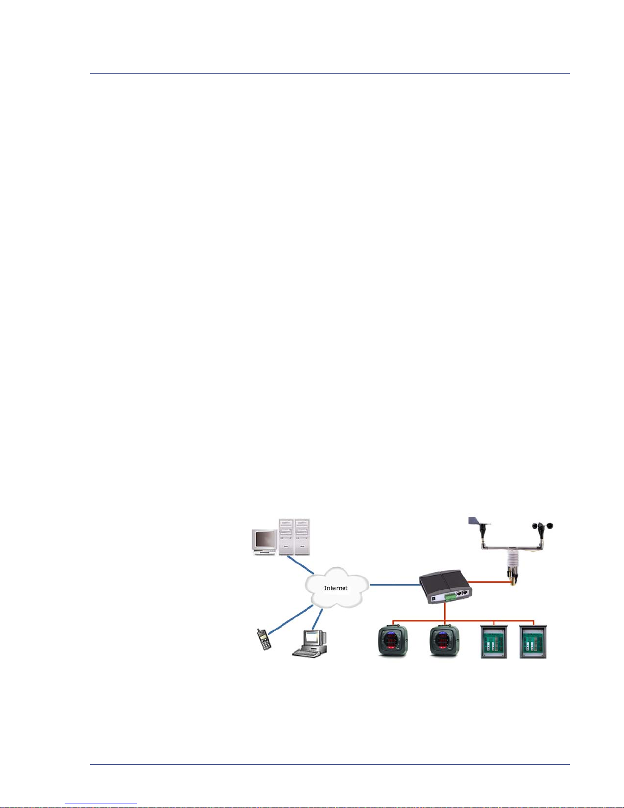
2.1 System Manager Overview
tem
Overview
The SolarMagic system manager is a lightweight Internet gateway and
data logger solution for remote data acquisition, which enables PV
system owners to benefit from advanced energy reports. The data
logger collects data from connected devices as energy meters, inverters
and weather stations, over the standard communications protocol
Modbus. System performance and energy information are logged into
a database on the Information Server, where it can be retrieved and
used for analysis via any standard web-browser enabled device by
logging in to the MYPVDATA site.
The system manager provides the following functions:
• AC Power Monitoring for Solar Production.
• Building Demand and Net Consumption Monitoring.
• Peak Demand Tracking.
• DC Monitoring to String Level.
Chapter 2 • About MYPVDATA® Services
Figure 2-1. Sys
• Real-time Power Values.
• Daily, Weekly and Monthly overviews.
• Local Data Storage Eliminates Need for Always-on Internet
Connection.
• Data Warehousing Facilitated on Internet Server.
• Web -based Presentation of Historical and Real-time Energy Data
in Graphs and Tables through MYPVDATA.com.
• Performance Alarming via Email and SMS.
5
Page 12

National Semiconductor • SolarMagic Weather Station User Guide
eather
Station Enclosure
Chapter 3 Planning
3.1 Enclosure
The SolarMagic weather station is housed in a painted galvanized steel
enclosure, suitable for outdoor mounting, type NEMA 4x. The
enclosure measures 10H x 8W x 4D.
Figure 3-1. W
3.1.2 Enclosure Specifications
• Type: 4-4x-12
• Material: 16 gauge painted galvanized steel
• Weight: 12lbs
• Size: 10”H x 8”W x 4”D
6
Page 13

3.2 Sensors Overview
Environmental sensors have many applications and therefore many
installation options. Where you locate the sensors for the weather
station is important in order to get accurate data. The sensors should
be located in a clear area on a level surface that represents the general
area of interest, and be away from obstructions such as buildings and
trees
All SolarMagic weather station weather sensors produce a 4–20mA
output signal. 4–20mA is an industrial standard signal for process
control monitoring. Most PLCs (Programmable Logic Controller) and
data acquisition systems accept this signal directly.
The communication module is already connected to the designated
input terminals on the input terminal block in the weather station. The
lead wires from the sensor will need to be connected to the input
terminals in the weather station enclosure. The weather station can be
installed up to 1000ft from the Data Logger and connects through a
twisted pair cable and RS-485 communication (National
Semiconductor recommends a size of stranded copper #18-22 twisted
pair with shielding and drain wire). The weather station also requires
24Vdc, which is typically sourced from the system manager
monitoring kit. The communication protocol is the widely spread
Modbus protocol.
Chapter 3 • Planning
The sensors are sampled continuously to provide real time data. Each
sensor draws between 4mA and 20mA depending on whether the
sensor is reading at the minimum or maximum of its range.
The weather station sensors include an assembly on a sturdy and
durable 1” OD stainless steel tube frame that can be mounted onto a
pre-existing base/mast or onto a tripod for upright installation. The
unit is designed for durability and endurance in harsh conditions. The
Solar Shield, a ventilated sun shield with high reflectiveness, low heat
retention, and low thermo conductivity, is provided as protection and a
mounting platform for the temperature sensor.
Choosing a proper installation location for weather sensors is
important to ensure accurate readings. For example, wind sensors
should not be installed too close to a building, as turbulence created by
the building can interfere with readings. To measure global irradiation
the solar irradiation sensor should be installed in direct sunlight on a
level surface (bubble level and leveling screws are included with
purchase) with similar sun exposure as the PV array.
7
Page 14

National Semiconductor • SolarMagic Weather Station User Guide
Solar
Irradiation Sensor
NOTE: Sensor Cable Length
Most sensors are shipped with a 25ft sensor lead cable. Make sure that the sensor
cables will reach. The sensor lead wires can be extended to a maximum length of
400ft if stranded #22AWG or larger wires are used.
If both the wind direction and wind speed sensors are purchased, the
weather station comes with a T-mounting bar with a 1" OD stainless
steel coupling unit and an Allen wrench to install the set screws during
installation. Individual wind sensors or solar irradiation sensors
include 1" stainless steel elbow couplers and an Allen wrench for the
set screws. The Solar Shield (with a stainless steel elbow coupler) can
be used for protection and easy installation of the Temperature and
Humidity sensors.
NOTE:
We recommend use of guy wires to support the weather sensor mast/base.
3.3 Solar Irradiation Sensor
The solar irradiation sensor or pyranometer is an instrument for
measuring solar irradiation from the hemispherical field of view
centered on the sensor. It measures the energy flux density of both
direct beam and diffuse sky irradiation passing through a horizontal
plane of known unit area.
Solar irradiation varies significantly among regions. Season and time
of day are major considerations, but surrounding terrain elevation,
man-made obstructions, and surrounding trees can also cause large
variations in locations with a small area.
Figure 3-2.
3.3.2 Solar Irradiation Sensor Specifications
• Output: 4–20mA
• Range: 0–1500 W/m2
• Accuracy: 1% of full scale
8
Page 15

• Operating Voltage: 10–36VDC
Speed
• Current Draw: Same as sensor output
• Warm Up Time: 3 seconds minimum
• Operating Temperature: –40°C to 55°C
• Size of Probe: 3" diameter × 1.5" high
• Weight: 0.25lb
3.4 Wind Speed Sensor
The wind speed sensor or anemometer produces a sine wave voltage
signal with a frequency that changes linearly with the wind speed. The
frequency is transformed into a 4–20mA sensor signal output.
Figure 3-3. Wind
Sensor
Chapter 3 • Planning
3.4.2 Wind Speed Sensor Specifications
• Output: 4–20mA
• Range: 0-100MPH
• Accuracy: 0.2MPH over the range 11 to 55MPH
• Operating Voltage: 10–36VDC
• Current Draw: Same as sensor output
• Warm Up Time: 3 seconds minimum
• Operating Temp: –40° to +55°C
• Size of Probe: 7" diameter × 8.5" long
• Weight: 1lb
3.5 Wind Direction Sensor
A wind direction sensor produces a ratio metric voltage signal. That
voltage signal is transformed into a 4–20mA sensor output signal.
9
Page 16

National Semiconductor • SolarMagic Weather Station User Guide
Wind Direction
Figure 3-4.
Sensor
3.5.2 Wind Direction Sensor Specifications
• Output: 4–20mA
• Range: 0 to 360° (352° electrical, 8° open)
• Accuracy: 1% of full scale
• Operating Voltage: 10–36VDC
• Current Draw: Same as sensor output
• Warm Up Time: 3 seconds minimum
• Operating Temp: –40° to +55°C
• Size: 8.5" diameter × 10 ½" long
• Weight: 1lb
3.5.3 Solar Shield
The solar shield is used to protect sensors, typically humidity and
temperature, from direct sunlight. Insert a sensor into one of the two
holes located on the underside of the shield. The shield provides a
friction lock so the sensors will not fall out. The sensors can be
removed by firmly twisting and pulling them out of the solar shield.
10
Page 17

Chapter 3 • Planning
Figure 3-5. Solar Shield
The shield comes with a stainless steel elbow that can be mounted on a
1” OD diameter tube. For best results ensure that the shield is mounted
vertically.
• Size: 4” diameter × 8 ½” long,
• Weight: 1 lb.
3.6 Ambient Temperature Sensor
Figure 3-5 shows the temperature sensor installed in the solar shield.
3.6.1 Ambient Temperature Sensor Specifications
• Output: 4–20mA
• Range: –50°C to 50°C
• Accuracy: ±0.2° F or ±0.1° C
• Operating Voltage: 10–36VDC
• Current Draw: same as sensor output
• Warm Up Time: five seconds minimum
• Operating Temperature: –50°C to 100°C
• Size of Probe: 0.75" diameter × 4.5" long
• Weight: 0.5lb
11
Page 18

National Semiconductor • SolarMagic Weather Station User Guide
PV Cell
Temperature Sensor
3.7 PV Cell Temperature Sensor
The PV Cell Temperature Sensor temperature sensor measures the
temperature of the aluminum heat sink located on the face.
Figure 3-6.
3.7.2 PV Cell Temperature Sensor Specifications
• Sensor Type: 100 Ohm Platinum Class A RTD
• Output: 4–20mA
• Range: –50° C to 85°C
• Accuracy: ±0.5° F or ±0.25°C
• Operating Voltage: 10–36VDC
• Current Draw: Same as sensor output
• Warm Up Time: 3 seconds minimum
• Storage Temperature: –55°C to 90°C
• Sensing Surface: 0.75” × 1.5” Aluminum
• Housing: 2.0W” × 1.1H” × 3.8L” ABS
• Weight: 13oz with 25’ of cable
3.8 Reference Cell/Temperature Sensor
The Reference Cell/Temperature sensor is a combination sensor with
an irradiation sensor via a temperature compensated mono-crystalline
silicon cell and a temperature sensor.
12
Page 19

Figure 3-7.
Reference
Cell/Temperature Sensor
Chapter 3 • Planning
3.8.2 Reference Cell/Temperature Sensor Specifications
• Solar Cell: Mono-crystalline Silicone (1.96in x 1.3in)
• Output: 4–20mA
• Range: –20° C to 70°C
• Irradiance Accuracy: +/- 5%
• Temperature Accuracy: +/- 2%
• Housing: 3.3W” × 1.5H” × 5.7L” Powder coated aluminum, IP65
• Weight: 8.8oz
3.9 Communication Module
The weather station includes a data acquisition module that provides
analog-to-digital conversion. The modules can be remotely controlled
using a set of commands, the Modbus RTU protocol. Communication
between the module and the SolarMagic Internet gateway / data logger
is via Modbus RTU over 2-wire RS-485 twisted pair. The weather
station module is set to 9600 baud in manufacturing for a more robust
communications network, and typically Modbus address 2.
3.9.1 Communication Module Specifications
The M-7017C is an 8-channel current input module.
• Channels: 8 current inputs
• Input Range: 4–20mA, ±20mA, or 0–20mA
13
Page 20

National Semiconductor • SolarMagic Weather Station User Guide
• Resolution: 16-bit
• Sample rate: Maximum 10 samples/second
• Bandwidth: 15.7Hz
• Accuracy: 0.1%
• Isolation: 3000VDC
• Indication LED Light For Power and Communication
• Communication: RS-485, Modbus RTU Protocol
• Power supply: 10–30VDC, 1.3W
14
Page 21

Chapter 4 Installation
!
4.1 Standard Version
4.1.1 Installing the SolarMagic Weather Station Enclosure
Chapter 4 • Installation
Mount the weather station enclosure out of direct sunlight in a
location where it will not be exposed to continuous water flow, snow
and ice build-up, and/or areas of extreme temperature. Install the
enclosure using the external enclosure mounting tabs.
The weather station enclosure may be mounted in a vertical (where the
door opens out) or a horizontal (where the door opens up) orientation.
Mount the weather station enclosure on the optionally supplied
base/mast or in its proximity.
CAUTION:
Drilling holes in the back plate is not recommended and will void the warranty.
For vertical installations, it is best to mount the enclosure directly to a
strut system, such as Uni-Strut. Both pieces of the strut system should
be at least 8" in length and be fastened to a stud bearing wall with (2)
1/4" lag bolts long enough to penetrate the stud at least 2.5". Fasten all
four corners of the enclosure to the strut with a 1/4"-20 X 3/4" bolt
(preferably stainless steal or galvanized), a 1/4" flat washer, and a 1/4"
channel nut.
4.1.2 Installing the optionally supplied Weather Sensors Mast
Mount the weather sensors on the frame using the provisions outlined
in the following sections. Secure the sensors to the frame with the set
screws using the supplied Allen wrench.
15
Page 22

National Semiconductor • SolarMagic Weather Station User Guide
!
Mount the base or mast for the weather station to a secure surface and
install guy wires if possible. It is very important to ground the mast or
base station for proper safety.
Attach the sensor frame to the base/mast.
4.1.3 Installing the Communication and Power
CAUTION: Turn Off Monitoring Panel
Before proceeding, make sure the power for the communication module and the
main Monitoring Panel (Internet Gateway / Data Logger) is switched off.
Connect the Modbus RS-485 communication cable (National
Semiconductor recommends a size of stranded copper #22AWG
twisted pair with shielding and drain wire) from the system manager
enclosure to one pair of the DATA+ and DATA– terminals. Connect
the shield drain wire to the shield terminal. Note this is not connected
to ground and the drain wire should only be connected to ground at
one point, typically in the system manager enclosure. The other pair of
Data + and Data – terminals is available for continuing the Modbus
data connection to another device.
Connect the weather station to the power supply using one pair of the
+Vs and GND terminals. The wire size for the 24Vdc power can be
determined using the specifications in the system manager User
Guide. The other pair of +Vs and GND terminals is available for
continuing the 24Vdc power connection to another device.
4.1.4 Installing the Weather Sensor Wires
Install your weather sensors so that they are easily accessible for
calibration purposes. You may need to clean, remove and/or reinstall
them in the future, so plan ahead!
NOTE: Sensor Cable Length
Most sensors are shipped with a 25ft sensor lead cable. Make sure that the sensor
cables will reach. The sensor lead wires can be extended to a maximum length of
400ft if stranded #22AWG or larger wires are used. If you extend or cut the sensor
wires, be sure to mark which sensor the wire is connected to.
Using a step bit or a 1/2" drill bit, drill one hole into the enclosure for
each sensor. Refer to the sensor references for recommended strain
relief placement. Using this order for the sensors will allow for cleaner
and easier wiring inside the enclosure.
16
Page 23

Figure 4-1.
Strain Relief
Connector
Z
Chapter 4 • Installation
NOTE:
After drilling through a powder coated enclosure, apply an anticorrosive solution
to reduce risk of corrosion. Allow the anticorrosive solution to adequately dry
before installing the strain relief connector. Be sure to completely remove all metal
filings from the interior and exterior of the enclosure using a vaccum cleaner
and/or brush.
Install one of the provided Sealcon strain relief connectors (size M12 X
1.5) for each sensor. Make sure that the gasket is properly inserted
between the connector and the outside of the enclosure and that the
fastener nut is firmly tightened down.
Connect the sensor to their respective input terminal in the enclosure,
See Appendix A for references. Make sure the polarity of the
conductors are marked and are connected to the proper terminals in
the enclosure.
4.1.5 Installing the Solar Irradiation Sensor
The sensor is a two-wire sensor using the red wire for power and the
black wire for the output signal.
WARNING: Do Not Connect When Energized
Do not connect the sensor wire if the communications module is energized.
Solar irradiation sensors should be mounted away from shadows,
reflective surfaces, and sources of light. Mounting the sensor on the
southernmost (for the northern hemisphere) part of the weather
station should minimize shading from the other weather station
sensors and hardware. The height the sensor is mounted is not critical
for the accuracy of the measurement. However, make sure it is
accessible to facilitate leveling, cleaning and calibration.
17
Page 24

National Semiconductor • SolarMagic Weather Station User Guide
Z
To m ea sure the module or array irradiation, ensure that the sensor is
placed on a level surface, use the alignment bolts to adjust the sensor
until it is level. Once the leveling alignment bolts are adjusted and
tightened then the irradiation sensor can be mounted at the same
angle and orientation as the PV modules. It is important the
irradiation sensor is mounted at the same angle and orientation in
order to determine the expected production of the PV system.
To measure global irradiation, mount the sensor on a level surface and
use the alignment bolts to adjust the sensor until it is level. Once the
leveling alignment bolts are adjusted, tighten them.
Remove the red cap to begin taking readings.
NOTE: Calibration
Calibration should be confirmed annually. Refer to Chapter 6 for calibration
procedures.
4.1.6 Installing the Wind Speed Sensor
The sensor is a two-wire sensor using the red wire for power and the
black wire for the output signal.
WARNING: Do Not Connect When Energized
Do not connect the sensor wire if the communications module is energized.
The sensor comes with a stainless steel elbow that can be mounted on
a 1” outside diameter tube. For best results ensure that the sensor is
mounted parallel to the ground surface located over open level terrain.
To measure the wind exposure of the PV array, National
Semiconductor recommends the wind sensor be installed in the
middle of the array at array height.
To measure the site wind conditions National Semiconductor
recommends the wind speed sensor be installed at a distance from
obstructions that is equal to five to ten times the height of nearby
buildings, trees, or other obstructions. For example if a parapet wall is
three feet higher than the wind sensor, then the wind sensor should be
installed 15 to 30 feet from the parapet wall.
The height over ground depends on the application and applicable
standards.
18
Page 25

4.1.7 Installing the Wind Direction Sensor
Z
Z
!
Z
The sensor is a two-wire sensor using the red wire for power and the
black wire for the output signal.
WARNING: Do Not Connect When Energized
Do not connect the sensor wire if the communications module is energized.
The ridge on the fixed portion of the sensor represents the 0° direction
of the sensor. Rotate the sensor so the ridge is aligns with the 0°
direction from a compass. The sensor comes with a stainless steel
elbow that can be mounted on a 1” outside diameter tube. For best
results ensure that the sensor is mounted parallel to the ground surface
located over open level terrain. National Semiconductor recommends
the wind direction sensor be installed near the wind speed sensor.
4.1.8 Installing the Ambient Temperature Sensor
The sensor is a two-wire sensor using the red wire for power and the
black wire for the output signal.
Chapter 4 • Installation
WARNING: Do Not Connect When Energized
Do not connect the sensor wire if the communications module is energized.
CAUTION:
Do not install the temperature sensor in direct sunlight.
For ambient temperature measurement applications the sensor should
be housed in a ventilated irradiation shield. To accurately measure the
ambient temperature we recommend that the sensor be no closer than
four times an obstruction’s height, at least 100ft. from large paved
areas, and located in an open level area that’s at least 30ft in diameter.
The open areas should be covered by short grass or, where grass does
not grow, the natural earth.
Avoid placing the sensor over rooftops, heat sources, high vegetation,
in shaded areas and areas that hold water.
4.1.9 Installing the PV Cell Temperature Sensor
The sensor is a two-wire sensor using the red wire for power and the
black wire for the output signal.
WARNING: Do Not Connect When Energized
Do not connect the sensor wire if the communications module is energized.
19
Page 26

National Semiconductor • SolarMagic Weather Station User Guide
!
Z
CAUTION:
Do not install the PV cell temperature sensor in direct sunlight.
Choose a PV module that will accurately model the average of the
panel temperature. Keep in mind that most PV modules on the edge
of an array are cooler because they have more air movement. After you
have chosen the correct module mark the appropriate location on the
back of the PV module to measure the PV cell temperature. This
location is typically under a PV cell and not the space between PV
cells.
For best operation, this sensor’s heat sink should be mounted flat
against the back of the solar panel. Mounting the sensor’s heat sink
over labels should be avoided if possible. A tube of silicone heat
transfer compound is provided with the sensor to ensure that the heat
sink is in proper contact with the solar panel and that the heat from
the panel is transferred efficiently to the sensor.
Apply an even coat of heat transfer compound to the surface of the
sensor as shown; making sure that the compound is a little bit higher
than the double stick tape. Use the alcohol pads provided with the
sensor to thoroughly clean the surface of the solar panel where the
sensor will be mounted. Allow this surface to dry completely before
mounting the sensor. Peel the backing from the adhesive tape and
press the sensor firmly against the solar panel. Tie the sensor cable to
the solar panel in a way that does not pull on the sensor.
20
4.1.10 Installing the Reference Cell/Temperature Sensor
The sensor is a four wire sensor using the red for power, black for
common/ground and orange and brown for the output signals.
WARNING: Do Not Connect When Energized
Do not connect the sensor wire if the communications module is energized.
The sensor has to brackets with each three M16 holes. Use at least one
M16 screw and washer at each bracket.
Mount the sensor in a location that best corresponds to your solar
installation. For recommendations, please contact National
Semiconductor Technical Support.
Page 27

Chapter 5 Commissioning
5.1 Powering Up
After all connections have been made, check the polarity of all wires
and connections to verify they are secured in the terminals and the
terminal screws are tight and connected to the proper terminals. If the
polarity of the wires is not correct, or they are connected to the wrong
terminals, you will not get weather data and may damage the sensors
or the communications module. After proper terminations have been
verified, it is ready to power on.
Chapter 5 • Commissioning
Turn on the power.
Verify the power LED is illuminated on the communication module.
Wait 15 minutes for the data to upload to the website and login to
MYPVDATA.com. Verify that the sensor readings on the MYPVDATA
site are available and accurate.
21
Page 28

National Semiconductor • SolarMagic Weather Station User Guide
Z
Chapter 6 Maintenance
The weather station sensors should be cleaned periodically. Sensors
can be cleaned using a damp cotton cloth.
NOTE: Do not submerge sensors
The sensors are water resistant, not waterproof.
6.1 Calibration
6.1.1 Temperature Sensor Calibration
Calibration should be confirmed annually.
To check the temperature sensor calibration you will need:
• 1 thermometer
• 3 containers of water
• 1 power supply
• 1 current meter
To calibrate the temperature sensor
Connect the sensor to the power supply and current meter in the
1
following way.
2 Attach the black wire to the positive input of the current meter.
3 Connect the ground terminal of the power supply to the ground of the
current meter.
4 Attach the red wire to the positive terminal of the power supply.
WARNING: Do Not Connect When Energized
Always connect the sensor with the power turned off.
22
Page 29

Chapter 6 • Maintenance
5 Fill a container of water with enough ice that it will not melt quickly.
6 Place the temperature sensor and thermometer into the container.
Turn on the power supply and the current meter. Let the sensor
stabilize for 30 minutes before taking any measurements.
7 Record the ice bath temperature, T
output current of the sensor, I
ICE
= _______, and record the
ICE
= _______.
8 Fill a container with enough warm water that it will not cool down
quickly.
9 Place the temperature sensor and thermometer into the container.
Turn on the power supply and the current meter. Let the sensor
stabilize for 30 minutes before taking any measurements.
10 Record the warm water temperature, T
the output current of the sensor, I
WARM
11 Calculate the relation between current and temperature:
a Calculate the current difference:
I
WARM
– I
= _______ = ∆I.
ICE
b Calculate the temperature difference:
T
c Calculate I
I
WARM
– T
WARM
– (∆I/∆T)(T
= _______ = ∆T.
ICE
B
WARM
) = _______ = IB.
d Calculate the low current value for the sensor:
(∆I/∆T) • (–50) + IB = _______ = I
HIGH
= _______, and record
WARM
= _______.
.
This current is the output current the sensor would produce if the
temperature were –50°C.
e Calculate the high current value for the sensor:
(∆I/∆T) • 50 + IB = _______ = I
LOW
.
This current is the output current the sensor would produce if the
temperature were 50°C.
12 Use these new current values calibrate the system that is monitoring
the sensor output.
23
Page 30

National Semiconductor • SolarMagic Weather Station User Guide
Chapter 7 Troubleshooting
Sensor reading incorrectly
Verify power source is supplying correct voltage.
1
2 Clean the sensor.
3 Confirm the sensor’s calibration.
4 Confirm the sensor is connected to the proper terminals.
7.1 Technical Support
For most efficient technical support please e-mail National
Semiconductor for technical support: support@solarmagic.com. Most
problems can be solved via email or call us at +1 (877) 765-6244.
When requesting technical support, please provide the following
information;
• Model #.
• Unit serial number.
• Site name and address, installer company name.
• Equipment purchaser name.
• Problem description.
Be prepared to describe the problem you are experiencing including
specific details of the application, installation, and any additional
pertinent information.
In the event that the equipment needs to be returned to the factory for
any reason, please call to obtain a RMA # (Return Material
Authorization). Do not return items without an RMA# displayed on
the outside of the package.
• Clean and decontaminate the sensor if necessary.
24
Page 31

Chapter 7 • Troubleshooting
• Include a written statement describing the problem(s).
• Insure your shipment; the warranty does not cover damage
incurred during transit.
• Send the package with shipping prepaid to our address at:
National Semiconductor
3875 Kifer Rd
Santa Clara, Ca 95051
25
Page 32

Page 33

Appendix A • Reference Diagrams
Appendix A Reference Diagrams
27
Page 34

National Semiconductor • SolarMagic Weather Station User Guide
A.1.1 Sensor Terminal Blocks
28
Page 35

A.1.2 Communications/Power Terminal Block
Appendix A • Reference Diagrams
29
Page 36

2900 Semiconductor Drive
Santa Clara, CA 95051
Phone 877-765-6244 Fax 866-816-1201
www.solarmagic.com
support@solarmagic.com
© 2010 National Semiconductor Corporation. National Semiconductor is a registered trademark and SolarMagic is a trademark of National Semiconductor Corporation. All
rights reserved. All other brand or product names are trademarks or registered trademarks of their respective holders.
 Loading...