


POEPHYTEREV-I / -E User
Guide
National Semiconductor
Application Note 1521
Youhao Xi Bradley Kennedy
April 4, 2008
Introduction
The POEPHYTEREV-I/-E evaluation board is a seamless design demonstrating National’s LM5072 PoE product (capable
of up to 24W) and DP83848I (single port 10/100Mb/s) Ethernet PHYTER® product. While both the LM5072 and the
DP83848 Ethernet PHY device have many advanced and
enticing features, this specific board is designed to demonstrate a subset of those features, specifically Power over
Ethernet. Two versions of this board are available. The –I
version has an RJ-45 connector that with integrated Ethernet
magnetics. The –E version has discrete RJ-45 connector and
Ethernet magnetics. The schematics of the board are available with this kit for duplication into an end application product.
For additional features of the PoE and PHY devices, individual device evaluation boards are separately available. For
detailed information about the complete functions and features of the LM5072 or DP83848 devices, refer to the relevant
datasheets. For applications where IEEE 802.3af must be
complied with and the power level is below 12.95W, refer to
Application Note AN-1455 (www.national.com/an/AN/
AN-1455.pdf). For detailed information about the Ethernet
PHYTER® circuit, refer to Application Note AN-1469
(www.national.com/an/AN/AN-1469.pdf).
This evaluation kit contains:
•
POEPHYTEREV-I or –E Evaluation board
•
Printed copy of this User's Guide
•
Board schematic
•
End User Licensing Agreement (EULA)
Scope of Applications
The POEPHYTEREV-I/-E evaluation kit (EK) is designed for
high power PD (PoE terminology - Powered Device) applications in which the maximum power exceeds the IEEE
802.3af’s 12.95W limit. The evaluation board features
National’s DP83848 10/100 Mb/s PHYTER® Ethernet Physical Layer Transceiver, so any equipment that provides a
standard IEEE 802.3, Clause 22 MII DTE interface; e.g.
SmartBits/Netcom box, is required as a data source for the
Ethernet device. The LM5072 is a 100V, high power PoE PD
and PWM controller. The evaluation board is capable of operating with both PoE and auxiliary (AUX) power sources. The
dc-dc converter stage of the power supply is implemented in
the versatile flyback converter topology.
Important Note on Circuit Board
Versions
There are two versions of PCBs being built, which can be
identified by the PCB serial number printed along the left edge
of the top side the circuit board. One version is labelled
551012916-001 Rev A, the other 551013040-001 Rev A. The
first version cannot modify the 3.3V output to higher voltages
because it is directly connected to the PHY through inner layers. It is modified on the second version such that higher
output voltage can be produced without damaging the PHY
circuit. The factory default output setting for both versions is
3.3V. Contact National on support to modify the latter version
to other output voltage.
In the following, descriptions apply to both versions of the circuit boards unless specifically indicated.
Features of the Evaluation Board
Seamless design solution, incorporating DP83848
PHYTER® single port 10/100 Mb/s Ethernet physical layer
transceiver and LM5072 High Power PoE PD and PWM controller.
Ethernet
•
Integrated or External magnetics and RJ45
•
Minimum configuration requirements:
2 PHY Addresses - 01h (default) or 03h
Status LEDs – board power, others dependant on LED
mode selected
Limited Strap Options – MDIX_EN, LED_CFG,
PWR_DWN/INT, MII/RMII Sel
RESET_N jumper
PWR_DWN/INT jumper
•
Connections for the following interfaces:
MIl/RMII Interface (IEEE 802.3 standard)
RJ-45 Cat-V Ethernet cable connector
JTAG header
25MHz_OUT header
Header for “ribbon cable” connection to MII/RMII
•
On-board clock – Crystal/Oscillator Dual Footprint
Power Over Ethernet
•
Isolated output voltage: 3.3V
•
Maximum output current: 7.3A
•
Maximum output power: 24W
•
Input voltage ranges:
PoE input voltage range: 39 to 57V
AUX input voltage range: 22 to 57V
•
Measured maximum efficiency:
DC to DC converter efficiency: 90% at 6A
Overall efficiency (including the input diode bridge):
86% at 6A
•
Overall Board Size: 5.50” x 3.96” x 0.70”
•
Switching frequency: 250 kHz
•
Optional input common-mode filter
PCB Layout Considerations
•
FR4 material
•
Trace symmetry within differential pair (±0.5")
•
Differential impedance 100 ohms, ±5%
•
Adjacent differential pairs spacing > 2X distance within a
differential pair, to minimize cross-talk and EMI
•
Trace length matching between differential pairs not
required
•
Uniform supply & ground plane
•
Void planes under magnetics, except for Chassis GND (at
RJ-45 edge only)
•
Combination of through-hole and surface mount
technology
•
Trace/space will be 0.007”/0.008” minimum
© 2008 National Semiconductor Corporation 202052 www.national.com
POEPHYTEREV-I / -E User Guide AN-1521
•
System interface will be via the MII connector, and MII
header
•
RJ-45 for network connection
•
JTAG access via 2x5 header
Usage setup and Configuration
This section contains information about the setup and configuration of the POEPHYTEREV-I/-E evaluation board, including descriptions of the card's interfaces, connectors,
jumpers and LEDs.
Power for the POEPHYTEREV board can be supplied by a
number of means:
•
MII connector J1
•
PoE over unused pairs
•
PoE over data pairs
•
External supply to P1
•
If 5V is supplied from the MII connector, the on-board
voltage regulator, U2, will convert 5V to 3.3V for the
PHYTER®. J7 should be removed.
•
If 3.3V is supplied from the MII connector, J7 needs to be
ON (See schematics for details).
•
Only applies to the circuit board version with PCB serial
number 551013040-001 Rev A: J7 should be shorted if the
PoE main output is set at 3.3V, which is the default factory
setting. To modify the output to other higher voltages, a
3.3V LDO should be installed onto U2 and J7 must be
open.
Address Settings:
The PMD address for the DP83848 Physical Layer device is
set by jumper J3.
•
Default board setting for the PHY Address is 01h
•
The board may be set to PHY Address 03h by adding
jumper J3
Table of Jumpers
Jumper Name Function
J1 MII Male Connector MII interface
J2 MII Header Alternative connection for MII signals
J3 PHYAD1 PHY Address strap pin
J4 MDIX_EN Enable/Disable MDIX mode. (Default is Auto-MDIX Enable)
J5 LED_CFG Set LED configuration. See datasheet
J6(Not populated)
J7 MII 3V3 option Use 3V3 MII supply
J8 PWR_DWN/INT Set Power Down and Interrupt Mode. See datasheet
J9 RESET_N Reset the device
J10 (Not populated)
J11 (Not populated)
J12 Pulse Jack Integrated Magnetic RJ-45 connector
Additional information for all options above may be found in the DP83848 datasheet.
Status indicators: LEDs
The POEPHYTEREV board supplies numerous status indicators via LEDs.
Status provided include:
Link - DS3*
Media Speed - DS2
Activity/Collision - DS4*
Ethernet Device Power - DS1
PoE Power - LED1
*Other status can be indicated by these LEDs. The alternate
status is set by adding jumper J5. Refer the DP83848
datasheet for additional information.
Ethernet Performance
The DP83848 PHYTER® supports line speed Ethernet network communications. Signal quality, which affects IEEE
compliance, can vary depending on board layout, power supplies, and components used, esp. isolation magnetics.
www.national.com 2
AN-1521

Software
No device specific software is required for this board National
does provide the integrity utility; a diagnostic and configuration package at:
www.national.com/appinfo/networks/ethernet_utility.html
An Important Note About the
Maximum Power Capability and
Cable Usage
The maximum output power is 24W. The user must make sure
that the Power Sourcing Equipment (PSE) in use can provide
at least 30W.
Important: Please note that the CAT-5 cable may not support
the said power over two pairs of twisted wires under strict
safety considerations. Users shall select the proper cable
wires to support the design power level without compromising
the applicable safety standards. Using an improper cable at
such power levels may violate safety regulations and may
cause damage.
A Note about PoE Input Potentials
PoE applications are typically -48V systems, in which the notations GND and -48V normally refer to the high and low input
potentials, respectively. However, for easy readability, the
LM5072 datasheet was written in the positive voltage convention with positive input potentials referenced to the VEE
pin of the LM5072. Therefore, when testing the evaluation
board with a bench power supply, the negative terminal of the
power supply is equivalent to the PoE system’s -8V potential,
and the positive terminal is equivalent to the PoE system
ground. To prevent confusion between the datasheet and this
application note, the same positive voltage convention is used
herein.
Schematics of the Evaluation Board
Figure 1, Figure 2 and Figure 3 shows the schematic of the
evaluation board.
3 www.national.com
AN-1521
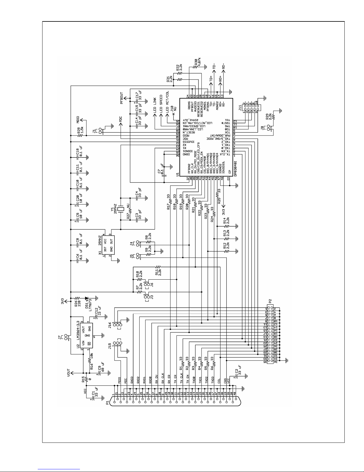
20205201
FIGURE 1. Evaluation Board Schematic Part 1. The Ethernet Circuit
www.national.com 4
AN-1521
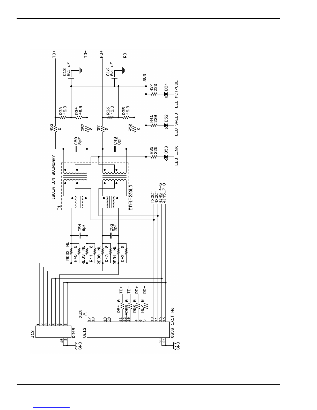
20205212
FIGURE 2. Evaluation Board Schematic Part 2: RJ45 connectors and Ethernet Magentics
5 www.national.com
AN-1521
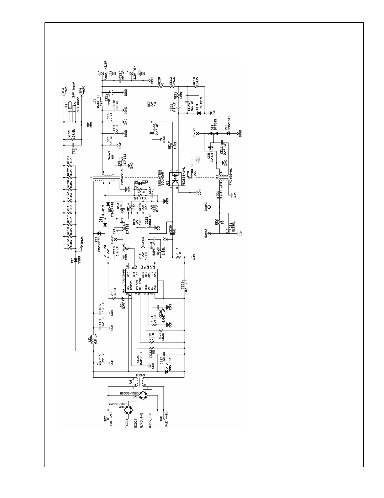
20205213
FIGURE 3. Evaluation Board Schematic Part 3: the PoE Circuit
www.national.com 6
AN-1521
 Loading...