


查询LMX2487SQX供应商
LMX2487
3.0 GHz - 6.0 GHz High Performance Delta-Sigma Low
LMX2487 High Performance Delta-Sigma Low Power Dual PLLatinum Frequency Synthesizer
February 2006
Power Dual PLLatinum
™
Frequency Synthesizers with
3.0 GHz Integer PLL
General Description
The LMX2487 is a low power, high performance delta-sigma
fractional-N PLL with an auxiliary integer-N PLL. It is fabricated using National Semiconductor’s advanced process.
With delta-sigma architecture, fractional spurs at lower offset
frequencies are pushed to higher frequencies outside the
loop bandwidth. The ability to push close in spur and phase
noise energy to higher frequencies is a direct function of the
modulator order. Unlike analog compensation, the digital
feedback technique used in the LMX2487 is highly resistant
to changes in temperature and variations in wafer processing. The LMX2487 delta-sigma modulator is programmable
up to fourth order, which allows the designer to select the
optimum modulator order to fit the phase noise, spur, and
lock time requirements of the system.
Serial data for programming the LMX2487 is transferred via
a three line high speed (20 MHz) MICROWIRE interface.
The LMX2487 offers fine frequency resolution, low spurs,
fast programming speed, and a single word write to change
the frequency. This makes it ideal for direct digital modulation applications, where the N counter is directly modulated
with information. The LMX2487 is available in a 24 lead
4.0 X 4.0 X 0.8 mm LLP package.
Applications
n Cellular phones and base stations
n Direct digital modulation applications
n Satellite and cable TV tuners
n WLAN Standards
Features
Quadruple Modulus Prescalers for Lower Divide Ratios
n RF PLL: 16/17/20/21 or 32/33/36/37
n IF PLL: 8/9 or 16/17
Advanced Delta Sigma Fractional Compensation
n 12 bit or 22 bit selectable fractional modulus
n Up to 4th order programmable delta-sigma modulator
Features for Improved Lock Times and Programming
n Fastlock / Cycle slip reduction
n Integrated time-out counter
n Single word write to change frequencies with Fastlock
Wide Operating Range
n LMX2487 RF PLL: 3.0 GHz to 6.0 GHz
Useful Features
n Digital lock detect output
n Hardware and software power-down control
n On-chip crystal reference frequency doubler.
n RF phase comparison frequency up to 50 MHz
n 2.5 to 3.6 volt operation with I
= 8.5 mA at 3.0 V
CC
Functional Block Diagram
20154701
PLLatinum™is a trademark of National Semiconductor Corporation.
© 2006 National Semiconductor Corporation DS201547 www.national.com
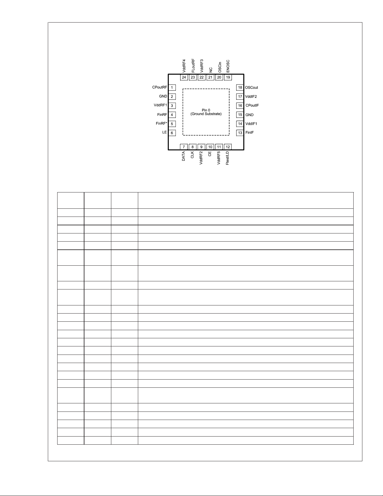
Connection Diagram
LMX2487
Pin Descriptions
Pin # Pin
0 GND - Ground Substrate. This is on the bottom of the package and must be grounded.
1 CPoutRF O RF PLL charge pump output.
2 GND - RF PLL analog ground.
3 VddRF1 - RF PLL analog power supply.
4 FinRF I RF PLL high frequency input pin.
5 FinRF* I RF PLL complementary high frequency input pin. Shunt to ground with a 100 pF
6 LE I MICROWIRE Load Enable. High impedance CMOS input. Data stored in the shift
7 DATA I MICROWIRE Data. High impedance binary serial data input.
8 CLK I MICROWIRE Clock. High impedance CMOS Clock input. Data for the various counters is
9 VddRF2 - Power supply for RF PLL digital circuitry.
10 CE I Chip Enable control pin. Must be pulled high for normal operation.
11 VddRF5 I Power supply for RF PLL digital circuitry.
12 Ftest/LD O Test frequency output / Lock Detect.
13 FinIF I IF PLL high frequency input pin.
14 VddIF1 - IF PLL analog power supply.
15 GND - IF PLL digital ground.
16 CPoutIF O IF PLL charge pump output
17 VddIF2 - IF PLL power supply.
18 OSCout O Buffered output of the OSCin signal.
19 ENOSC I Oscillator enable. When this is set to high, the OSCout pin is enabled regardless of the
20 OSCin I Reference Input.
21 NC I This pin must be left open.
22 VddRF3 - Power supply for RF PLL digital circuitry.
23 FLoutRF O RF PLL Fastlock Output. Also functions as Programmable TRI-STATE CMOS output.
24 VddRF4 - RF PLL analog power supply.
Name
Top View
24-Pin LLP (SQ)
20154722
I/O Pin Description
capacitor.
registers is loaded into the internal latches when LE goes HIGH
clocked into the 24 bit shift register on the rising edge
state of other pins or register bits.
www.national.com 2
Absolute Maximum Ratings (Notes 1, 2)
LMX2487
Parameter Symbol
Power Supply Voltage V
Voltage on any pin with GND = 0V V
Storage Temperature Range T
Lead Temperature (Solder 4 sec.) T
Min Typ Max
CC
i
s
L
-0.3 4.25 V
-0.3 VCC+0.3 V
-65 +150 ˚C
Value
Units
+260 ˚C
Recommended Operating Conditions
Parameter Symbol
Power Supply Voltage (Note 1) V
Operating Temperature T
Note 1: “Absolute Maximum Ratings” indicate limits beyond which damage to the device may occur. "Recommended Operating Conditions" indicate conditions for
which the device is intended to be functional, but do not guarantee specific performance limits. For guaranteed specifications and test conditions, see the Electrical
Characteristics. The guaranteed specifications apply only for the test conditions listed. The voltage at all the power supply pins of VddRF1, VddRF2, VddRF3,
VddRF4, VddRF5, VddIF1 and VddIF2 must be the same. V
through all these power pins.
Note 2: This Device is a high performance RF integrated circuit with an ESD rating
be done at ESD-free workstations.
Electrical Characteristics (V
CC
A
will be used to refer to the voltage at these pins and ICCwill be used to refer to the sum of all currents
CC
= 3.0V; -40˚C ≤ TA≤ +85˚C unless otherwise specified)
CC
Min Typ Max
2.5 3.0 3.6 V
-40 25 +85 ˚C
<
2 kV and is ESD sensitive. Handling and assembly of this device should only
Symbol Parameter Conditions
Icc PARAMETERS
I
RF
CC
IF
I
CC
TOTAL
I
CC
PD Power Down Current
I
CC
Power Supply Current,
RF Synthesizer
Power Supply Current,
IF Synthesizer
Power Supply Current,
Entire Synthesizer
IF PLL OFF
RF PLL ON
Charge Pump TRI-STATE
IF PLL ON
RF PLL OFF
Charge Pump TRI-STATE
IF PLL ON
RF PLL ON
Charge Pump TRI-STATE
CE = ENOSC = 0V
CLK, DATA, LE = 0V
RF SYNTHESIZER PARAMETERS
f
FinRF
p
FinRF
Operating
Frequency
LMX2487
Input Sensitivity 3000 - 6000 MHz -10 0 dBm
RF_P = 16 3000 4000
RF_P = 32 3000 6000
Phase Detector
f
COMP
Frequency
(Note 3)
RF_CPG = 0
CPoutRF
CPoutRF
=VCC/2
=VCC/2
I
CPoutRF
SRCE
RF Charge Pump
Source Current
(Note 4)
V
RF_CPG = 1
V
... ... µA
RF_CPG = 15
V
CPoutRF
=VCC/2
Value
Value
Min Typ Max
5.7 mA
2.5 mA
8.5 mA
<
1µA
95 µA
190 µA
1520 µA
Units
50 MHz
Units
MHz
www.national.com3

Electrical Characteristics (V
= 3.0V; -40˚C ≤ TA≤ +85˚C unless otherwise specified) (Continued)
CC
LMX2487
Symbol Parameter Conditions
RF SYNTHESIZER PARAMETERS
RF Charge Pump Sink
I
CPoutRF
SINK
Current
(Note 4)
RF Charge Pump
I
CPoutRF
TRI
TRI-STATE Current
Magnitude
Magnitude of RF CP
|I
CPoutRF
%MIS |
Sink vs. CP Source
Mismatch
|I
|I
CPoutRF
CPoutRF
%V |
%T |
Magnitude of RF CP
Current vs. CP Voltage
Magnitude of RF CP
Current vs. Temperature
IF SYNTHESIZER PARAMETERS
f
FinIF
p
FinIF
f
COMP
I
CPoutIF
I
CPoutIF
SRCE
SINK
Operating Frequency
IF Input Sensitivity -10 +5 dBm
Phase Detector
Frequency
IF Charge Pump Source
Current
IF Charge Pump Sink
Current
IF Charge Pump
I
CPoutIF
TRI
TRI-STATE Current
Magnitude
|I
|I
|I
CPoutIF
CPoutIF
CPoutIF
%MIS |
%V |
%TEMP
Magnitude of IF CP Sink
vs. CP Source Mismatch
Magnitude of IF CP
Current vs. CP Voltage
Magnitude of IF CP
Current vs. Temperature
OSCILLATOR PARAMETERS
f
OSCin
v
OSCin
I
OSCin
Oscillator Operating
Frequency
Oscillator Input
Sensitivity
Oscillator Input Current -100 100 µA
SPURS
Spurs in band(Note 5) -55 dBc
RF_CPG = 0
CPoutRF
=VCC/2
V
RF_CPG = 1
V
CPoutRF
=VCC/2
Value
Min Typ Max
-95 µA
-190 µA
Units
... ... µA
RF_CPG = 15
V
0.5 ≤ V
V
V
T
A
0.5 ≤ V
T
A
V
=VCC/2
CPoutRF
≤ VCC-0.5 2 10 nA
=
RF_CPG
>
2 3 10 %
RF_CPG ≤ 2 3 13 %
≤ VCC-0.5
CPoutRF
/2
CC
= 25˚C
CPoutRF
CPoutRF
= 25˚C
=VCC/2 4 %
CPoutRF
IF_P = 8 250 2000
IF_P = 16 250 3000
-1520 µA
28 %
MHz
10 MHz
V
CPoutIF=VCC
V
CPoutIF=VCC
0.5 ≤ V
V
CPoutIF=VCC
= 25˚C
T
A
0.5 ≤ V
= 25˚C
T
A
V
CPoutIF=VCC
/2 3.5 mA
/2 -3.5 mA
≤ VCCRF -0.5 2 10 nA
CPoutIF
CPoutIF
/2
≤ VCC-0.5
18 %
410 %
/2 4 %
OSC2X = 0 5 110 MHz
OSC2X = 1 5 20 MHz
0.5 V
CC
V
P-P
www.national.com 4

LMX2487
Electrical Characteristics (V
Symbol Parameter Conditions
= 3.0V; -40˚C ≤ TA≤ +85˚C unless otherwise specified) (Continued)
CC
Value
Min Typ Max
PHASE NOISE
RF_CPG = 0 -202
RF Synthesizer
L
F1Hz
RF
Normalized Phase Noise
Contribution(Note 6)
RF_CPG = 1 -204
RF_CPG = 3 -206
RF_CPG = 7 -210
RF_CPG = 15 -210
IF Synthesizer
IF
L
F1Hz
Normalized Phase Noise
-209 dBc/Hz
Contribution
DIGITAL INTERFACE (DATA, CLK, LE, ENOSC, CE, Ftest/LD, FLoutRF)
V
IH
V
IL
I
IH
I
IL
V
OH
V
OL
High-Level Input Voltage 1.6 V
CC
Low-Level Input Voltage 0.4 V
High-Level Input Current VIH=V
CC
-1.0 1.0 µA
Low-Level Input Current VIL= 0 V -1.0 1.0 µA
High-Level Output
Voltage
Low-Level Output
Voltage
= -500 µA VCC-0.4 V
I
OH
= 500 µA 0.4 V
I
OL
MICROWIRE INTERFACE TIMING
t
CS
t
CH
t
CWH
t
CWL
t
ES
t
EW
Note 3: For Phase Detector Frequencies above 20 MHz, Cycle Slip Reduction (CSR) may be required. Legal divide ratios are also required.
Note 4: Refer to table in Section 2.4.2 RF_CPG -- RF PLL Charge Pump Gain for complete listing of charge pump currents.
Note 5: In order to measure the in-band spur, the fractional word is chosen such that when reduced to lowest terms, the fractional numerator is one. The spur offset
frequency is chosen to be the comparison frequency divided by the reduced fractional denominator. The loop bandwidth must be sufficiently wide to negate the
impact of the loop filter. Measurement conditions are: Spur Offset Frequency = 10 kHz, Loop Bandwidth = 100 kHz, Fraction = 1/2000, Comparison Frequency =
20 MHz, RF_CPG = 7, DITH = 0, VCO Frequency = 3 GHz, and a 4th Order Modulator (FM = 0). These are relatively consistent over tuning range.
Note 6: Normalized Phase Noise Contribution is defined as: L
measured at an offset frequency, f, ina1HzBandwidth. The offset frequency, f, must be chosen sufficiently smaller than the PLL loop bandwidth, yet large enough
to avoid substantial phase noise contribution from the reference source. Measurement conditions are: Offset Frequency = 11 kHz, Loop Bandwidth = 100 kHz for
RF_CPG = 7, Fraction = 1/2000, Comparison Frequency = 20 MHz, FM = 0, DITH = 0, VCO Frequency = 3 GHz.
Data to Clock Set Up
Time
See MICROWIRE Input Timing 25 ns
Data to Clock Hold Time See MICROWIRE Input Timing 8 ns
Clock Pulse Width High See MICROWIRE Input Timing 25 ns
Clock Pulse Width Low See MICROWIRE Input Timing 25 ns
Clock to Load Enable
Set Up Time
Load Enable Pulse
Width
See MICROWIRE Input Timing 25 ns
See MICROWIRE Input Timing 25 ns
(f) = L(f) – 20log(N) – 10log(f
N
) where L(f) is defined as the single side band phase noise
COMP
Units
dBc/Hz
V
MICROWIRE INPUT TIMING DIAGRAM
20154775
www.national.com5

Typical Performance Characteristics : Sensitivity (Note 7)
LMX2487
RF PLL Fin Sensitivity
= 25˚C, RF_P = 32
T
A
20154745
RF PLL Fin Sensitivity
= 3.0 V, RF_P = 32
V
CC
20154746
www.national.com 6

Typical Performance Characteristics : Sensitivity (Note 7) (Continued)
IF PLL Fin Sensitivity
T
= 25˚C, IF_P = 16
A
LMX2487
IF PLL Fin Sensitivity
= 3.0 V, IF_P = 16
V
CC
20154747
20154748
www.national.com7

Typical Performance Characteristics : Sensitivity (Note 7) (Continued)
LMX2487
OSCin Sensitivity
T
= 25˚C, OSC_2X = 0
A
20154749
OSCin Sensitivity
= 3.0 V, OSC_2X = 0
V
CC
20154756
www.national.com 8

Typical Performance Characteristics : Sensitivity (Note 7) (Continued)
OSCin Sensitivity
T
= 25˚C, OSC_2X =1
A
LMX2487
OSCin Sensitivity
= 3.0 V, OSC_2X = 1
V
CC
20154773
20154774
www.national.com9

Typical Performance Characteristic : FinRF Input Impedance (Note 7)
LMX2487
20154768
FinRF Input Impedance
Frequency (MHz) Real (Ohms) Imaginary (Ohms)
3000 39 -94
3200 37 -86
3400 33 -78
3600 30 -72
3800 28 -69
4000 26 -66
4250 24 -63
4500 23 -60
4750 22 -57
5000 20 -54
5250 19 -50
5500 18 -49
5750 17 -47
6000 17 -45
6250 16 -44
6500 16 -42
6750 16 -40
7000 16 -39
www.national.com 10

Typical Performance Characteristic : FinIF Input Impedance (Note 7)
20154754
FinIF Input Impedance
Frequency (MHz) Real (Ohms) Imaginary (Ohms)
100 508 -233
150 456 -215
200 420 -206
250 403 -205
300 370 -207
400 344 -215
500 207 -223
600 274 -225
700 242 -225
800 242 -225
900 214 -222
1000 171 -208
1200 137 -191
1400 112 -176
1600 91 -158
1800 76 -139
2000 62 -122
2200 51 -105
2300 46 -96
2400 42 -88
2600 37 -74
2800 29 -63
3000 25 -54
LMX2487
www.national.com11

Typical Performance Characteristic : OSCin Input Impedance (Note 7)
LMX2487
Frequency (MHz) Powered Up Powered Down
Real Imaginary Magnitude Real Imaginary Magnitude
5 1730 -3779 4157 392 -8137 8146
10 846 -2236 2391 155 -4487 4490
20 466 -1196 1284 107 -2215 2217
30 351 -863 932 166 -1495 -1504
40 316 -672 742 182 -1144 1158
50 278 -566 631 155 -912 925
60 261 -481 547 153 -758 774
70 252 -425 494 154 -652 669
80 239 -388 456 147 -576 595
90 234 -358 428 145 -518 538
100 230 -337 407 140 -471 492
110 225 -321 392 138 -436 458
120 219 -309 379 133 -402 123
130 214 -295 364 133 -374 397
140 208 -285 353 132 -349 373
150 207 -279 348 133 -329 355
20154755
www.national.com 12

Typical Performance Characteristics : Currents (Note 7)
Power Supply Current
CE = High
LMX2487
RF PLL Charge Pump Current
= 3.0 Volts
V
CC
20154759
20154767
www.national.com13

Typical Performance Characteristics : Currents (Note 7) (Continued)
LMX2487
IF PLL Charge Pump Current
V
= 3.0 Volts
CC
20154765
Charge Pump Leakage
RF PLL
= 3.0 Volts
V
CC
20154764
www.national.com 14

Typical Performance Characteristics : Currents (Note 7) (Continued)
Charge Pump Leakage
IF PLL
= 3.0 Volts
V
CC
LMX2487
20154763
Note 7: Typical performance characteristics do not imply any sort of guarantee. Guaranteed specifications are in the electrical characteristics section.
www.national.com15

Bench Test Setups
LMX2487
Charge Pump Current Measurement Procedure
The above block diagram shows the test procedure for testing the RF and IF charge pumps. These tests include absolute current
level, mismatch, and leakage measurement. In order to measure the charge pump currents, a signal is applied to the high
frequency input pins. The reason for this is to guarantee that the phase detector gets enough transitions in order to be able to
change states. If no signal is applied, it is possible that the charge pump current reading will be low due to the fact that the duty
cycle is not 100%. The OSCin Pin is tied to the supply. The charge pump currents can be measured by simply programming the
phase detector to the necessary polarity. For instance, in order to measure the RF charge pump, a 10 MHz signal is applied to
the FinRF pin. The source current can be measured by setting the RF PLL phase detector to a positive polarity, and the sink
current can be measured by setting the phase detector to a negative polarity. The IF PLL currents can be measured in a similar
way. Note that the magnitude of the RF PLL charge pump current is controlled by the RF_CPG bit. Once the charge pump
currents are known, the mismatch can be calculated as well. In order to measure leakage, the charge pump is set to a TRI-STATE
mode by enabling the RF_CPT and IF_CPT bits. The table below shows a summary of the various charge pump tests.
Current Test RF_CPG RF_CPP RF_CPT IF_CPP IF_CPT
RF Source 0 to 15 0 0 X X
RF Sink 0 to 15 1 0 X X
RF TRI-STATE X X 1 X X
IF Source X X X 0 0
IF Sink X X X 1 0
IF TRI-STATE X X X X 1
20154769
www.national.com 16

Bench Test Setups (Continued)
Charge Pump Current Specification Definitions
LMX2487
20154750
I1 = Charge Pump Sink Current at V
I2 = Charge Pump Sink Current at V
I3 = Charge Pump Sink Current at V
I4 = Charge Pump Source Current at V
I5 = Charge Pump Source Current at V
I6 = Charge Pump Source Current at V
CPout
CPout
CPout
CPout
CPout
CPout
= Vcc - ∆V
= Vcc/2
= ∆V
= Vcc - ∆V
= Vcc/2
= ∆V
∆V = Voltage offset from the positive and negative supply rails. Defined to be 0.5 volts for this part.
refers to either V
v
CPout
I
refers to either I
CPout
CPoutRF
CPoutRF
or I
or V
CPoutIF
CPoutIF
Charge Pump Output Current Variation vs. Charge Pump Output Voltage
20154751
Charge Pump Sink Current vs. Charge Pump Output Source Current Mismatch
20154752
Charge Pump Output Current Variation vs. Temperature
20154753
www.national.com17

Bench Test Setups (Continued)
LMX2487
Frequency Input Pin DC Blocking Capacitor Corresponding Counter Default Counter Value MUX Value
OSCin 1000 pF RF_R / 2 50 14
FinRF 100 pF// 1000 pF RF_N / 2 502 + 2097150 / 4194301 15
FinIF 100 pF IF_N / 2 534 13
OSCin 1000 pF IF_R / 2 50 12
20154770
Sensitivity Measurement Procedure
Sensitivity is defined as the power level limits beyond which the output of the counter being tested is off by 1 Hz or more of its
expected value. It is typically measured over frequency, voltage, and temperature. In order to test sensitivity, the MUX[3:0] word
is programmed to the appropriate value. The counter value is then programmed to a fixed value and a frequency counter is set
to monitor the frequency of this pin. The expected frequency at the Ftest/LD pin should be the signal generator frequency divided
by twice the corresponding counter value. The factor of two comes in because the LMX2487 has a flip-flop which divides this
frequency by two to make the duty cycle 50% in order to make it easier to read with the frequency counter. The frequency counter
input impedance should be set to high impedance. In order to perform the measurement, the temperature, frequency, and voltage
is set to a fixed value and the power level of the signal is varied. Note that the power level at the part is assumed to be 4 dB less
than the signal generator power level. This accounts for 1 dB for cable losses and 3 dB for the pad. The power level range where
the frequency is correct at the Ftest/LD pin to within 1 Hz accuracy is recorded for the sensitivity limits. The temperature,
frequency, and voltage can be varied in order to produce a family of sensitivity curves. Since this is an open-loop test, the charge
pump is set to TRI-STATE and the unused side of the PLL (RF or IF) is powered down when not being tested. For this part, there
are actually four frequency input pins, although there is only one frequency test pin (Ftest/LD). The conditions specific to each pin
are shown in above table.
Note that for the RF N counter, a fourth order fractional modulator is used in 22-bit mode with a fraction of 2097150 / 4194301
is used. The reason for this long fraction is to test the RF N counter and supporting fractional circuitry as completely as possible.
www.national.com 18

Bench Test Setups (Continued)
20154771
Input Impedance Measurement Procedure
The above block diagram shows the test setup used for measuring the input impedance for the LMX2487. The DC blocking
capacitor used between the input SMA connector and the pin being measured must be changed to a zero Ohm resistor. This
procedure applies to the FinRF, FinIF, and OSCin pins. The basic test procedure is to calibrate the network analyzer, ensure that
the part is powered up, and then measure the input impedance. The network analyzer can be calibrated by using either calibration
standards or by soldering resistors directly to the evaluation board. An open can be implemented by putting no resistor, a short
can be implemented by soldering a zero ohm resistor as close as possible to the pin being measured, and a short can be
implemented by soldering two 100 ohm resistors in parallel as close as possible to the pin being measured. Calibration is done
with the PLL removed from the PCB. This requires the use of a clamp down fixture that may not always be generally available.
If no clamp down fixture is available, then this procedure can be done by calibrating up to the point where the DC blocking
capacitor usually is, and then implementing port extensions with the network analyzer. Zero ohm resistor is added back for the
actual measurement. Once the setup is calibrated, it is necessary to ensure that the PLL is powered up. This can be done by
toggling the power down bits (RF_PD and IF_PD) and observing that the current consumption indeed increases when the bit is
disabled. Sometimes it may be necessary to apply a signal to the OSCin pin in order to program the part. If this is necessary,
disconnect the signal once it is established that the part is powered up. It is useful to know the input impedance of the PLL for
the purposes of debugging RF problems and designing matching networks. Another use of knowing this parameter is make the
trace width on the PCB such that the input impedance of this trace matches the real part of the input impedance of the PLL
frequency of operation. In general, it is good practice to keep trace lengths short and make designs that are relatively resistant
to variations in the input impedance of the PLL.
LMX2487
www.national.com19

Functional Description (Note 8)
1.0 GENERAL
LMX2487
The LMX2487 consists of integrated N counters, R counters,
and charge pumps. The TCXO, VCO and loop filter are
supplied external to the chip. The various blocks are described below.
1.1 TCXO, OSCILLATOR BUFFER, AND R COUNTER
The oscillator buffer must be driven single-ended by a signal
source, such as a TCXO. The OSCout pin is included to
provide a buffered output of this input signal and is active
when the OSC_OUT bit is set to one. The ENOSC pin can
be also pulled high to ensure that the OSCout pin is active,
regardless of the status of the registers in the LMX2487.
The R counter divides this TCXO frequency down to the
comparison frequency.
1.2 PHASE DETECTOR
The maximum phase detector operating frequency for the IF
PLL is straightforward, but it is a little more involved for the
RF PLL since it is fractional. The maximum phase detector
frequency for the LMX2487 RF PLL is 50 MHz. However, this
is not possible in all circumstances due to illegal divide ratios
of the N counter. The crystal reference frequency also limits
the phase detector frequency, although the doubler helps
with this limitation. There are trade-offs in choosing the
phase detector frequency. If this frequency is run higher,
then phase noise will be lower, but lock time may be increased due to cycle slipping and the capacitors in the loop
filter may become rather large.
1.3 CHARGE PUMP
For the majority of the time, the charge pump output is high
impedance, and the only current through this pin is the
Tri-State leakage. However, it does put out fast correction
pulses that have a width that is proportional to the phase
error presented at the phase detector.
The charge pump converts the phase error presented at the
phase detector into a correction current. The magnitude of
this current is theoretically constant, but the duty cycle is
proportional to the phase error. For the IF PLL, this current is
not programmable, but for the RF PLL it is programmable in
16 steps. Also, the RF PLL allows for a higher charge pump
current to be used when the PLL is locking in order to reduce
the lock time.
1.4 LOOP FILTER
The loop filter design can be rather involved. In addition to
the regular constraints and design parameters, delta-sigma
PLLs have the additional constraint that the order of the loop
filter should be one greater than the order of the delta sigma
modulator. This rule of thumb comes from the requirement
that the loop filter must roll off the delta sigma noise at 20
dB/decade faster than it rises. However, since the noise can
not have infinite power, it must eventually roll off. If the loop
bandwidth is narrow, this requirement may not be necessary.
For the purposes of discussion in this datasheet, the pole of
the loop filter at 0 Hz is not counted. So a second order filter
has 3 components, a 3rd order loop filter has 5 components,
and the 4th order loop filter has 7 components. Although a
5th order loop filter is theoretically necessary for use with a
4th order modulator, typically a 4th order filter is used in this
case. The loop filter design, especially for higher orders can
be rather involved, but there are many simulation tools and
references available, such as the one given at the end of the
functional description block.
1.5 N COUNTERS AND HIGH FREQUENCY INPUT PINS
The N counter divides the VCO frequency down to the
comparison frequency. Because prescalers are used, there
are limitations on how small the N value can be. The N
counters are discussed in greater depth in the programming
section. Since the input pins to these counters ( FinRF and
FinIF ) are high frequency, layout considerations are important.
High Frequency Input Pins, FinRF and FinIF
It is generally recommended that the VCO output go through
a resistive pad and then through a DC blocking capacitor
before it gets to these high frequency input pins. If the trace
length is sufficiently short (
the pad may not be necessary, but a series resistor of about
39 ohms is still recommended to isolate the PLL from the
VCO. The DC blocking capacitor should be chosen at least
to be 27 pF. It may turn out that the frequency is above the
self-resonant frequency of the capacitor, but since the input
impedance of the PLL tends to be capacitive, it actually is a
benefit to exceed the tune frequency. The pad and the DC
blocking capacitor should be placed as close to the PLL as
possible
Complementary High Frequency Pin, FinRF*
These inputs may be used to drive the PLL differentially, but
it is very common to drive the PLL in a single ended fashion.
A shunt capacitor should be placed at the FinRF* pin. The
value of this capacitor should be chosen such that the impedance, including the ESR of the capacitor, is as close to
an AC short as possible at the operating frequency of the
PLL. 100 pF is a typical value.
1.6 POWER PINS, POWER DOWN, AND POWER UP
MODES
It is recommended that all of the power pins be filtered with
a series 18 ohm resistor and then placing two capacitors
shunt to ground, thus creating a low pass filter. Although it
makes sense to use large capacitor values in theory, the
ESR ( Equivalent Series Resistance ) is greater for larger
capacitors. For optimal filtering minimize the sum of the ESR
and theoretical impedance of the capacitor. It is therefore
recommended to provide two capacitors of very different
sizes for the best filtering. 1 µF and 100 pF are typical
values. The small capacitor should be placed as close as
possible to the pin.
The power down state of the LMX2487 is controlled by many
factors. The one factor that overrides all other factors is the
CE pin. If this pin is low, the part will be powered down.
Asserting a high logic level on this pin is necessary to power
up the chip, however, there are other bits in the programming
registers that can override this and put the PLL back in a
power down state. Provided that the voltage on the CE pin is
high, programming the RF_PD and IF_PD bits to zero guarantees that the part will be powered up. Programming either
one of these bits to one will power down the appropriate
section of the synthesizer, provided that the ATPU bit does
not override this.
<
1/10th of a wavelength ), then
www.national.com 20

Functional Description (Note 8)
(Continued)
ATPU
Bit Enabled +
Write to RF
CE Pin RF_PD
Low X X Powered Down
High X Yes Powered Up
High 0 No Powered Up
High 1 No Powered Down
1.7 DIGITAL LOCK DETECT OPERATION
The RF PLL digital lock detect circuitry compares the difference between the phase of the inputs of the phase detector
to a RC generated delay of e. To indicate a locked state
(Lock = HIGH) the phase error must be less than the e RC
delay for 5 consecutive reference cycles. Once in lock (Lock
= HIGH), the RC delay is changed to approximately δ.To
indicate an out of lock state (Lock = LOW), the phase error
must become greater δ. The values of e and δ are dependent
on which PLL is used and are shown in the table below:
PLL e δ
RF 10 ns 20 ns
IF 15 ns 30 ns
N Counter PLL State
(Asynchronous)
( Asynchronous )
LMX2487
When the PLL is in the power down mode and the Ftest/LD
pin is programmed for the lock detect function, it is forced
LOW. The accuracy of this circuit degrades at higher comparison frequencies. To compensate for this, the DIV4 word
should be set to one if the comparison frequency exceeds 20
MHz. The function of this word is to divide the comparison
frequency presented to the lock detect circuit by 4. Note that
if the MUX[3:0] word is set such as to view lock detect for
both PLLs, an unlocked (LOW) condition is shown whenever
either one of the PLLs is determined to be out of lock.
20154704
www.national.com21

Functional Description (Note 8)
(Continued)
LMX2487
1.8 CYCLE SLIP REDUCTION AND FASTLOCK
The LMX2487 offers both cycle slip reduction (CSR) and
Fastlock with timeout counter support. This means that it
requires no additional programming overhead to use them. It
is generally recommended that the charge pump current in
the steady state be 8X or less in order to use cycle slip
reduction, and 4X or less in steady state in order to use
Fastlock. The next step is to decide between using Fastlock
or CSR. This determination can be made based on the ratio
of the comparison frequency ( f
(BW).
Comparison
Frequency
(f
f
COMP
1.25 MHz
f
COMP
f
COMP
)
COMP
≤ 1.25 MHz
<
≤ 2 MHz
>
2 MHz Same or worse
Fastlock
Noticeable better
than CSR
Marginally better
than CSR
than CSR
Cycle Slip Reduction (CSR)
Cycle slip reduction works by reducing the comparison frequency during frequency acquisition while keeping the same
loop bandwidth, thereby reducing the ratio of the comparison
frequency to the loop bandwidth. In cases where the ratio of
the comparison frequency exceeds about 100 times the loop
bandwidth, cycle slipping can occur and significantly degrade lock times. The greater this ratio, the greater the
benefit of CSR. This is typically the case of high comparison
frequencies. In circumstances where there is not a problem
with cycle slipping, CSR provides no benefit. There is a glitch
when CSR is disengaged, but since CSR should be disengaged long before the PLL is actually in lock, this glitch is not
an issue. A good rule of thumb for CSR disengagement is to
do this at the peak time of the transient response. Because
this time is typically much sooner than Fastlock should be
disengaged, it does not make sense to use CSR and Fastlock in combination.
Fastlock
Fastlock works by increasing the loop bandwidth only during
frequency acquisition. In circumstances where the comparison frequency is less than or equal to 2 MHz, Fastlock may
provide a benefit beyond what CSR can offer. Since Fastlock
also reduces the ratio of the comparison frequency to the
loop bandwidth, it may provide a significant benefit in cases
where the comparison frequency is above 2 MHz. However,
CSR can usually provide an equal or larger benefit in these
cases, and can be implemented without using an additional
resistor. The reason for this restriction on frequency is that
Fastlock has a glitch when it is disengaged. As the time of
engagement for Fastlock decreases and becomes on the
order of the fast lock time, this glitch grows and limits the
benefits of Fastlock. This effect becomes worse at higher
comparison frequencies. There is always the option of reducing the comparison frequency at the expense of phase
noise in order to satisfy this constraint on comparison frequency. Despite this glitch, there is still a net improvement in
lock time using Fastlock in these circumstances. When using
Fastlock, it is also recommended that the steady state
charge pump state be 4X or less. Also, Fastlock was origi-
) to loop bandwidth
COMP
Cycle Slip
Reduction
Likely to provide
a benefit,
provided that
f
COMP
BW
( CSR )
>
100 X
nally intended only for second order filters, so when implementing it with higher order filters, the third and fourth poles
can not be too close in, or it will not be possible to keep the
loop filter well optimized when the higher charge pump current and Fastlock resistor are engaged.
1.8.1 Using Cycle Slip Reduction (CSR) to Avoid Cycle
Slipping
Once it is decided that CSR is to be used, the cycle slip
reduction factor needs to be chosen. The available factors
are 1/2, 1/4, and 1/16. In order to preserve the same loop
characteristics, it is recommended that the following constraint be satisfied: (Fastlock Charge Pump Current) /
(Steady State Charge Pump Current) = CSR
In order to satisfy this constraint, the maximum charge pump
current in steady state is 8X for a CSR of 1/2, 4X for a CSR
of 1/4, and 1X for a CSR of 1/16. Because the PLL phase
noise is better for higher charge pump currents, it makes
sense to choose CSR only as large as necessary to prevent
cycle slipping. Choosing it larger than this will not improve
lock time, and will result in worse phase noise.
Consider an example where the desired loop bandwidth in
steady state is 100 kHz and the comparison frequency is 20
MHz. This yields a ratio of 200. Cycle slipping may be
present, but would not be too severe if it was there. If a CSR
factor of 1/2 is used, this would reduce the ratio to 100 during
frequency acquisition, which is probably sufficient. A charge
pump current of 8X could be used in steady state, and a
factor of 16X could be used during frequency acquisition.
This yields a ratio of 1/2, which is equal to the CSR factor
and this satisfies the above constraint. In this circumstance,
it could also be decided to just use 16X charge pump current
all the time, since it would probably have better phase noise,
and the degradation in lock time would not be too severe.
1.8.2 Using Fastlock to Improve Lock Times
20154740
Once it is decided that Fastlock is to be used, the loop
bandwidth multiplier, K, is needed in order to determine the
theoretical impact of Fastlock on the loop bandwidth and the
resistor value, R2p, that is switched in parallel during Fastlock. This ratio is calculated as follows: K = ( Fastlock
Charge Pump Current)/(Steady State Charge Pump
Current )
K Loop Bandwidth R2p Value Lock Time
1 1.00 X Open 100 %
2 1.41 X R2/0.41 71 %
3 1.73 X R2/0.73 58%
4 2.00 X R2 50%
8 2.83 X R2/1.83 35%
9 3.00 X R2/2 33%
16 4.00 X R2/3 25%
The above table shows how to calculate the fastlock resistor
and theoretical lock time improvement, once the ratio , K, is
www.national.com 22

Functional Description (Note 8)
(Continued)
known. This all assumes a second order filter (not counting
the pole at 0 Hz). However, it is generally recommended that
the loop filter order be one greater than the order of the delta
sigma modulator, which means that a second order filter is
never recommended. In this case, the value for R2p is
typically about 80% of what it would be for a second order
filter. Because the fastlock disengagement glitch gets larger
and it is harder to keep the loop filter optimized as the K
value becomes larger, designing for the largest possible
value for K usually, but not always yields the best improvement in lock time. To get a more accurate estimate requires
more simulation tools, or trial and error.
1.8.3 Capacitor Dielectric Considerations for Lock
Time
The LMX2487 has a high fractional modulus and high
charge pump gain for the lowest possible phase noise. One
consideration is that the reduced N value and higher charge
pump may cause the capacitors in the loop filter to become
larger in value. For larger capacitor values, it is common to
have a trade-off between capacitor dielectric quality and
physical size. Using film capacitors or NPO/COG capacitors
yields the best possible lock times, where as using X7R or
Z5R capacitors can increase lock time by 0 – 500%. However, it is a general tendency that designs that use a higher
compare frequency tend to be less sensitive to the effects of
capacitor dielectrics. Although the use of lesser quality dielectric capacitors may be unavoidable in many circumstances, allowing a larger footprint for the loop filter capacitors, using a lower charge pump current, and reducing the
fractional modulus are all ways to reduce capacitor values.
Capacitor dielectrics have very little impact on phase noise
and spurs.
1.9 FRACTIONAL SPUR AND PHASE NOISE
CONTROLS
Control of the fractional spurs is more of an art than an exact
science. The first differentiation that needs to be made is
between primary fractional and sub-fractional spurs. The
Note 8: For more information concerning delta-sigma PLLs, loop filter design, cycle slip reduction, Fastlock, and many other topics, visit wireless.national.com. Here
there is the EasyPLL simulation tool and an online reference called "PLL Performance, Simulation, and Design", by Dean Banerjee.
primary fractional spurs are those that occur at increments of
the channel spacing only. The sub-fractional spurs are those
that occur at a smaller resolution than the channel spacing,
usually one-half or one-fourth. There are trade-offs between
fractional spurs, sub-fractional spurs, and phase noise. The
rules of thumb presented in this section are just that. There
will be exceptions. The bits that impact the fractional spurs
are FM and DITH, and these bits should be set in this order.
The first step to do is choose FM, for the delta sigma
modulator order. It is recommended to start with FM=3for
a third order modulator and use strong dithering. In general,
there is a trade-off between primary and sub-fractional
spurs. Choosing the highest order modulator (FM = 0 for 4th
order) typically provides the best primary fractional spurs,
but the worst sub-fractional spurs. Choosing the lowest
modulator order (FM = 2 for 2nd order), typically gives the
worst primary fractional spurs, but the best sub-fractional
spurs. Choosing FM = 3, for a 3rd order modulator is a
compromise.
The second step is to choose DITH, for dithering. Dithering
has a very small impact on primary fractional spurs, but a
much larger impact on sub-fractional spurs. The only problem is that it can add a few dB of phase noise, or even more
if the loop bandwidth is very wide. Disabling dithering (DITH
= 0), provides the best phase noise, but the sub-fractional
spurs are worst (except when the fractional numerator is 0,
and in this case, they are the best). Choosing strong dithering (DITH = 2) significantly reduces sub-fractional spurs, if
not eliminating them completely, but adds the most phase
noise. Weak dithering (DITH = 1) is a compromise.
The third step is to tinker with the fractional word. Although
1/10 and 400/4000 are mathematically the same, expressing
fractions with much larger fractional numerators often improve the fractional spurs. Increasing the fractional denominator only improves spurs to a point. A good practical limit
could be to keep the fractional denominator as large as
possible, but not to exceed 4095, so it is not necessary to
use the extended fractional numerator or denominator.
LMX2487
www.national.com23

Programming Description
2.0 GENERAL PROGRAMMING INFORMATION
LMX2487
The 24-bit data registers are loaded through a MICROWIRE Interface. These data registers are used to program the R counter,
the N counter, and the internal mode control latches. The data format of a typical 24-bit data register is shown below. The control
bits CTL [3:0] decode the register address. On the rising edge of LE, data stored in the shift register is loaded into one of the
appropriate latches (selected by address bits). Data is shifted in MSB first. Note that it is best to program the N counter last, since
doing so initializes the digital lock detector and Fastlock circuitry. Note that initialize means it resets the counters, but it does NOT
program values into these registers. The exception is when 22-bit is not being used. In this case, it is not necessary to program
the R7 register.
MSB LSB
DATA [21:0] CTL [3:0]
23 4 3 2 1 0
2.0.1 Register Location Truth Table
The control bits CTL [3:0] decode the internal register address. The table below shows how the control bits are mapped to the
target control register.
C3 C2 C1 C0 DATA Location
xxx0 R0
0011 R1
0101 R2
0111 R3
1001 R4
1011 R5
1101 R6
1111 R7
2.0.2 Control Register Content Map
Because the LMX2487 registers are complicated, they are organized into two groups, basic and advanced. The first four registers
are basic registers that contain critical information necessary for the PLL to achieve lock. The last 5 registers are for features that
optimize spur, phase noise, and lock time performance. The next page shows these registers.
www.national.com 24

1001
[3:0]
IF_P MUX
LMX2487
RF_
CPP
IF_
CPP
OSC
_OUT
_2X
0 OSC
FM
[1:0]
DATA[19:0] ( Except for the RF_N Register, which is [22:0] ) C3 C2 C1 C0
DATA[19:0] ( Except for the RF_N Register, which is [22:0] ) C3 C2 C1 C0
Complete Register Map The complete register map shows all the functionality of all registers, including the last five.
[1:0]
Quick Start Register Map Although it is highly recommended that the user eventually take advantage of all the modes of the LMX2487, the quick start register map is shown in order
Programming Description (Continued)
for the user to get the part up and running quickly using only those bits critical for basic functionality. The following default conditions for this programming state are a third order
REGISTER 23 22 21 20 19 18 17 16 15 14 13 12 11 10 987654 3 2 1 0
delta-sigma modulator in 12-bit mode with no dithering and no Fastlock.
R0 RF_N[10:0] RF_FN[11:0] 0
R1 RF_PD RF_P RF_R[5:0] RF_FD[11:0] 0 0 1 1
R2 IF_PD IF_N[18:0] 0 1 0 1
R3 0001 RF_CPG[3:0] IF_R[11:0] 0 1 1 1
R4 0 0 100000110001110000 1 0 0 1
R0 RF_N[10:0] RF_FN[11:0] 0
R1 RF_PD RF_P RF_R[5:0] RF_FD[11:0] 0011
R2 IF_PD IF_N[18:0] 0101
R3 ACCESS[3:0] RF_CPG[3:0] IF_R[11:0] 0111
REGISTER 23 22 21 20 19 18 17 16 15 14 13 12 11 10 9 8 7 6 5 4 3210
R4 ATPU 0 1000 DITH
R5 RF_FD[21:12] RF_FN[21:12] 1011
R6 CSR[1:0] RF_CPF[3:0] RF_TOC[13:0] 1101
R7 0 0 00000000DIV4 0 1 0 0 1 IF_RST RF_RST IF_CPT RF_CPT 1111
www.national.com25

Programming Description (Continued)
2.1 R0 REGISTER
LMX2487
Note that this register has only one control bit, so the N counter value to be changed with a single write statement to the PLL.
REGISTER 23 22 21 20 19 18 17 16 15 14 13 12 11 10 9 87654321 0
DATA[22:0] C0
R0 RF_N[10:0] RF_FN[11:0] 0
2.1.1 RF_FN[11:0] -- Fractional Numerator for RF PLL
Refer to section 2.6.1 for a more detailed description of this control word.
2.1.2 RF_N[10:0] -- RF N Counter Value
The RF N counter contains an 16/17/20/21 and a 32/33/36/37 prescaler. The N counter value can be calculated as follows:
N = RF_P·RF_C + 4·RF_B + RF_A
RF_C ≥Max{RF_A, RF_B} , for N-2
RF_B counter has an unused bit, where this extra bit is used by the delta-sigma modulator for the purposes of modulation.
Consult the tables below for valid operating ranges for each prescaler.
FM
-1 ... N+2FMis a necessary condition. This rule is slightly modified in the case where the
Operation with the 16/17/20/21 Prescaler (RF_P=0)
RF_N RF_N [10:0]
RF_C [5:0] RF_B [2:0] RF_A [1:0]
<
49 N Values Below 49 are Illegal.
49-63 Legal Divide Ratios are:
2nd Order Modulator: 49-61
3rd Order Modulator: 51-59
4th Order Modulator: 55
64-79 Legal Divide Ratios are:
2nd and 3rd Order Modulator: All
4th Order Modulator: 64-75
80 000101 0 0 0 0 0
... ...... 0 . . . .
1023 111111 0 1 1 1 1
>
1023 N values above 1023 are prohibited.
Operation with the 32/33/36/37 Prescaler (RF_P=1)
RF_N
<
97 N Values Below 97 are Illegal.
97-226 Legal Divide Ratios are:
227--230 Legal Divide Ratios are:
231 000111 0 0 1 1 1
... ...... . . . . .
2039 111111 1 0 1 1 1
2040-2043 Possible with a second or third order delta-sigma engine.
2044-2045 Possible only with a second order delta-sigma engine.
>
2045 N values greater than 2045 are prohibited.
www.national.com 26
RF_C [5:0] RF_B [2:0] RF_A [1:0]
2nd Order Modulator: 97-109, 129-145, 161-181, 193-217, 225-226
3rd Order Modulator: 99-107, 131-143, 163-179, 195-215
4th Order Modulator: 103, 135-139, 167-175, 199-211
2nd and 3rd Order Modulator: All
RF_N [10:0]
4th Order Modulator: None

Programming Description (Continued)
2.2 R1 REGISTER
REGISTER 23 22 21 20 19 18 17 16 15 14 13 12 11 10 9 87654 3 2 1 0
DATA[19:0] C3 C2 C1 C0
R1 RF_PD RF_P RF_R[5:0] RF_FD[11:0] 0 0 1 1
2.2.1 RF_FD[11:0] -- RF PLL Fractional Denominator
The function of these bits are described in section 2.6.2.
2.2.2 RF_R [5:0] -- RF R Divider Value
The RF R Counter value is determined by this control word. Note that this counter does allow values down to one.
R Value RF_R[5:0]
1 000001
... . . . . . .
63 111111
2.2.3 RF_P -- RF Prescaler bit
The prescaler used is determined by this bit.
RF_P Prescaler Maximum Frequency
0 16/17/20/21 4000 MHz
1 32/33/36/37 6000 MHz
LMX2487
2.2.4 RF_PD -- RF Power Down Control Bit
When this bit is set to 0, the RF PLL operates normally. When it is set to one, the RF PLL is powered down and the RF Charge
pump is set to a TRI-STATE mode. The CE pin and ATPU bit also control power down functions, and will override the RF_PD bit.
The order of precedence is as follows. First, if the CE pin is LOW, then the PLL will be powered down. Provided this is not the
case, the PLL will be powered up if the ATPU bit says to do so, regardless of the state of the RF_PD bit. After the CE pin and the
ATPU bit are considered, then the RF_PD bit then takes control of the power down function for the RF PLL.
www.national.com27

Programming Description (Continued)
2.3 R2 REGISTER
LMX2487
REGISTER 23 22 21 20 19 18 17 16 15 14 13 12 11 10 9 8 7654 3210
DATA[19:0] C3 C2 C1 C0
R2 IF_PD IF_N[18:0] 0101
2.3.1 IF_N[18:0] -- IF N Divider Value
IF_N Counter Programming with the 8/9 Prescaler (IF_P=0)
N Value
≤23 N values less than or equal to 23 are prohibited because IF_B ≥ 3 is required.
24-55 Legal divide ratios in this range are:
56 0000000000001110000
57 0000000000001110001
... ...................
262143 1111111111111110111
IF_B IF_A
24-27, 32-36, 40-45, 48-54
IF_N[18:0]
Operation with the 16/17 Prescaler (IF_P=1)
N Value
IF_B IF_A
≤47 N values less than or equal to 47 are prohibited because IF_B ≥ 3 is required.
48-239 Legal divide ratios in this range are:
48-51, 64-68, 80-85, 96-102, 112-119, 128-136, 144-153, 160-170, 176-187, 192-204, 208-221, 224-238
240 0000000000011110000
241 0000000000011110001
... ...................
524287 1111111111111111111
2.3.4 IF_PD -- IF Power Down Bit
When this bit is set to 0, the IF PLL operates normally. When it is set to 1, the IF PLL powers down and the output of the IF PLL
charge pump is set to a TRI-STATE mode. If the ATPU bit is set and register R0 is written to, the IF_PD will be reset to 0 and the
IF PLL will be powered up. If the CE pin is held low, the IF PLL will be powered down, overriding the IF_PD bit.
www.national.com 28

Programming Description (Continued)
2.4 R3 REGISTER
REGISTER 23 22 21 20 19 18 17 16 15 14 13 12 11 10 987654 3210
DATA[19:0] C3 C2 C1 C0
R3 ACCESS[3:0] RF_CPG[3:0] IF_R[11:0] 0111
2.4.1 IF_R[11:0] -- IF R Divider Value
For the IF R divider, the R value is determined by the IF_R[11:0] bits in the R3 register. The minimum value for IF_R is 3.
R Value IF_R[11:0]
3 000000000011
... ............
4095 111111111111
2.4.2 RF_CPG -- RF PLL Charge Pump Gain
This is used to control the magnitude of the RF PLL charge pump in steady state operation.
RF_CPG Charge Pump State Typical RF Charge Pump Current at 3 Volts (µA)
01X 95
1 2X 190
2 3X 285
3 4X 380
4 5X 475
5 6X 570
6 7X 665
7 8X 760
8 9X 855
9 10X 950
10 11X 1045
11 12X 1140
12 13X 1235
13 14X 1330
14 15X 1425
15 16X 1520
LMX2487
2.4.3 ACCESS -- Register Access word
It is mandatory that the first 5 registers R0-R4 be programmed. The programming of registers R5-R7 is optional. The
ACCESS[3:0] bits determine which additional registers need to be programmed. Any one of these registers can be individually
programmed. According to the table below, when the state of a register is in default mode, all the bits in that register are forced
to a default state and it is not necessary to program this register. When the register is programmable, it needs to be programmed
through the MICROWIRE. Using this register access technique, the programming required is reduced up to 37%.
ACCESS Bit Register Location Register Controlled
ACCESS[0] R3[20] Must be set to 1
ACCESS[1] R3[21] R5
ACCESS[2] R3[22] R6
ACCESS[3] R3[23] R7
The default conditions the registers is shown below:
Register 23 22 21 20 19 18 17 16 15 14 13 12 11 10 987654 3210
Data[19:0] C3 C2 C1 C0
R4 R4 Must be programmed manually.
R5 00000000000000000000 1011
R6 00000000000000000000 1101
R7 00000000000010010000 1111
www.national.com29

Programming Description (Continued)
This corresponds to the following bit settings.
LMX2487
Register Bit Location Bit Name Bit Description Bit Value Bit State
R4[23] ATPU Autopowerup 0 Disabled
R4[17:16] DITH Dithering 2 Strong
R4[15:16] FM Modulator Order 3 3rd Order
R4[23] OSC_2X Oscillator Doubler 0 Disabled
R4
R5
R6
R7
R4[23] OSC_OUT OSCout Pin Enable 0 Disabled
R4[23] IF_CPP IF Charge Pump Polarity 1 Positive
R4[23] RF_CPP RF Charge Pump Polarity 1 Positive
R4[23] IF_P IF PLL Prescaler 1 16/17
R4[7:4] MUX Ftest/LD Output 0 Disabled
R5[23:14] RF_FD[21:12] Extended Fractional Denominator 0 Disabled
R5[13:4] RF_FN[21:12] Extended Fractional Numerator 0 Disabled
R6[23:22] CSR Cycle Slip Reduction 0 Disabled
R6[21:18] RF_CPF Fastlock Charge Pump Current 0 Disabled
R6[17:4] RF_TOC RF Timeout Counter 0 Disabled
R7[13] DIV4 Lock Detect Adjustment 0 Disabled (Fcomp ≤ 20 MHz)
R7[7] IF_RST IF PLL Counter Reset 0 Disabled
R7[6] RF_RST RF PLL Counter Reset 0 Disabled
R7[5] IF_CPT IF PLL Tri-State 0 Disabled
R7[4] RF_CPT RF PLL Tri-State 0 Disabled
www.national.com 30

Programming Description (Continued)
2.5 R4 REGISTER
This register controls the conditions for the RF PLL in Fastlock.
REGISTER 23 22 21 20 19 18 17 16 15 14 13 12 11 10 9 8 7654 3210
DATA[19:0] C3 C2 C1 C0
R4 ATPU01000
2.5.1 MUX[3:0] Frequency Out & Lock Detect MUX
These bits determine the output state of the Ftest/LD pin.
MUX[3:0] Output Type Output Description
0000High Impedance Disabled
0001 Push-Pull General purpose output, Logical “High” State
0010 Push-Pull General purpose output, Logical “Low” State
0011 Push-Pull RF & IF Digital Lock Detect
0100 Push-Pull RF Digital Lock Detect
0101 Push-Pull IF Digital Lock Detect
0110 Open Drain RF & IF Analog Lock Detect
0111 Open Drain RF Analog Lock Detect
1000 Open Drain IF Analog Lock Detect
1001 Push-Pull RF & IF Analog Lock Detect
1010 Push-Pull RF Analog Lock Detect
1011 Push-Pull IF Analog Lock Detect
1100 Push-Pull IF R Divider divided by 2
1101 Push-Pull IF N Divider divided by 2
1110 Push-Pull RF R Divider divided by 2
1111 Push-Pull RF N Divider divided by 2
DITH
[1:0]FM[1:0]
OSC_2XOSC_
0
OUT
IF_
CPP
RF_
CPP
IF_P
MUX
[3:0]
1001
LMX2487
2.5.2 IF_P -- IF Prescaler
When this bit is set to 0, the 8/9 prescaler is used. Otherwise the 16/17 prescaler is used.
IF_P IF Prescaler Maximum Frequency
0 8/9 800 MHz
1 16/17 800 MHz
2.5.3 RF_CPP -- RF PLL Charge Pump Polarity
RF_CPP RF Charge Pump Polarity
0 Negative
1 Positive (Default)
2.5.4 IF_CPP -- IF PLL Charge Pump Polarity
For a positive phase detector polarity, which is normally the case, set this bit to 1. Otherwise set this bit for a negative phase
detector polarity.
IF_CPP IF Charge Pump Polarity
0 Negative
1 Positive
2.5.5 OSC_OUT Oscillator Output Buffer Enable
OSC_OUT OSCout Pin
0 Disabled (High Impedance)
1 Buffered output of OSCin pin
www.national.com31

Programming Description (Continued)
2.5.6 OSC2X -- Oscillator Doubler Enable
LMX2487
When this bit is set to 0, the oscillator doubler is disabled and the TCXO frequency presented to the IF R and RF R counters is
equal to that of the input frequency of the OSCin pin. When this bit is set to 1, the TCXO frequency presented to the RF R counter
is doubled. Phase noise added by the doubler is negligible.
OSC2X Frequency Presented to RF R Counter Frequency Presented to IF R Counter
0f
1 2xf
OSCin
OSCin
2.5.7 FM[1:0] -- Fractional Mode
Determines the order of the delta-sigma modulator. Higher order delta-sigma modulators reduce the spur levels closer to the
carrier by pushing this noise to higher frequency offsets from the carrier. In general, the order of the loop filter should be at least
one greater than the order of the delta-sigma modulator in order to allow for sufficient roll-off.
FM Function
0 Fractional PLL mode with a 4th order delta-sigma modulator
1 Disable the delta-sigma modulator. Recommended for test use only.
2 Fractional PLL mode with a 2nd order delta-sigma modulator
3 Fractional PLL mode with a 3rd order delta-sigma modulator
2.5.8 DITH[1:0] -- Dithering Control
Dithering is a technique used to spread out the spur energy. Enabling dithering can reduce the main fractional spurs, but can also
give rise to a family of smaller spurs. Whether dithering helps or hurts is application specific. Enabling the dithering may also
increase the phase noise. In most cases where the fractional numerator is zero, dithering usually degrades performance.
Dithering tends to be most beneficial in applications where there is insufficient filtering of the spurs. This often occurs when the
loop bandwidth is very wide or a higher order delta-sigma modulator is used. Dithering tends not to impact the main fractional
spurs much, but has a much larger impact on the sub-fractional spurs. If it is decided that dithering will be used, best results will
be obtained when the fractional denominator is at least 1000.
DITH Dithering Mode Used
0 Disabled
1 Weak Dithering
2 Strong Dithering
3 Reserved
f
OSCin
2.5.9 ATPU -- PLL Automatic Power Up
When this bit is set to 1, both the RF and IF PLL power up when the R0 register is written to. When the R0 register is written to,
the PD_RF and PD_IF bits are changed to 0 in the PLL registers. The exception to this case is when the CE pin is low. In this
case, the ATPU function is disabled.
www.national.com 32

Programming Description (Continued)
2.6 R5 REGISTER
REGISTER 23 22 21 20 19 18 17 16 15 14 13 12 11 10 987654 3210
DATA[19:0] C3 C2 C1 C0
R5 RF_FD[21:12] RF_FN[21:12] 1011
2.6.1 Fractional Numerator Determination { RF_FN[21:12], RF_FN[11:0], ACCESS[1] }
In the case that the ACCESS[1] bit is 0, then the part operates in 12-bit fractional mode, and the RF_FN2[21:12] bits become do
not care bits. When the ACCESS[1] bit is set to 1, the part operates in 22-bit mode and the fractional numerator is expanded from
12 to 22-bits.
Fractional RF_FN[21:12]
Numerator ( These bits only apply in 22- bit mode)
0
1 000000000001
... ............
4095 111111111111
4096 0000000001000000000000
... ......................
4194303 1111111111111111111111
2.6.2 Fractional Denominator Determination { RF_FD[21:12], RF_FD[11:0], ACCESS[1]}
In the case that the ACCESS[1] bit is 0, then the part is operates in the 12-bit fractional mode, and the RF_FD[21:12] bits become
do not care bits. When the ACCESS[1] is set to 1, the part operates in 22-bit mode and the fractional denominator is expanded
from 12 to 22-bits.
Fractional RF_FD[21:12] RF_FD[11:0]
Denominator ( These bits only apply in 22- bit mode)
0 In 12- bit mode, these are do not care.
1 000000000001
... ............
4095 111111111111
4096 0000000001000000000000
... ......................
4194303 1111111111111111111111
In 12- bit mode, these are do not care.
<
In 22- bit mode, for N
these bits should be all set to 0.
In 22- bit mode, for N
these bits should be all set to 0.
4096,
<
4096,
000000000000
000000000000
RF_FN[11:0]
LMX2487
www.national.com33

Programming Description (Continued)
2.7 R6 REGISTER
LMX2487
REGISTER 23 22 21 20 19 18 17 16 15 14 13 12 11 10 987654 3210
DATA[19:0] C3 C2 C1 C0
R6 CSR[1:0] RF_CPF[3:0] RF_TOC[13:0] 1101
2.7.1 RF_TOC -- RF Time Out Counter and Control for FLoutRF Pin
The RF_TOC[13:0] word controls the operation of the RF Fastlock circuitry as well as the function of the FLoutRF output pin.
When this word is set to a value between 0 and 3, the RF Fastlock circuitry is disabled and the FLoutRF pin operates as a general
purpose CMOS TRI-STATE I/O. When RF_TOC is set to a value between 4 and 16383, the RF Fastlock mode is enabled and
the FLoutRF pin is utilized as the RF Fastlock output pin. The value programmed into the RF_TOC[13:0] word represents two
times the number of phase detector comparison cycles the RF synthesizer will spend in the Fastlock state.
RF_TOC Fastlock Mode Fastlock Period [CP events] FLoutRF Pin Functionality
0 Disabled N/A High Impedance
1 Manual N/A Logic “0” State.
Forces all Fastlock conditions
2 Disabled N/A Logic “0” State
3 Disabled N/A Logic “1” State
4 Enabled 4X2 = 8 Fastlock
5 Enabled 5X2 = 10 Fastlock
… Enabled … Fastlock
16383 Enabled 16383X2 = 32766 Fastlock
2.7.2 RF_CPF -- RF PLL Fastlock Charge Pump Current
Specify the charge pump current for the Fastlock operation mode for the RF PLL. Note that the Fastlock charge pump current,
steady state current, and CSR control are all interrelated.
RF_CPF RF Charge Pump State Typical RF Charge Pump Current at 3 Volts (µA)
01X 95
1 2X 190
2 3X 285
3 4X 380
4 5X 475
5 6X 570
6 7X 665
7 8X 760
8 9X 855
9 10X 950
10 11X 1045
11 12X 1140
12 13X 1235
13 14X 1330
14 15X 1425
15 16X 1520
www.national.com 34

Programming Description (Continued)
2.7.3 CSR[1:0] -- RF Cycle Slip Reduction
CSR controls the operation of the Cycle Slip Reduction Circuit. This circuit can be used to reduce the occurrence of phase
detector cycle slips. Note that the Fastlock charge pump current, steady state current, and CSR control are all interrelated. Refer
to section 1.8 for information on how to use this.
CSR CSR State Sample Rate Reduction Factor
0 Disabled 1
1 Enabled 1/2
2 Enabled 1/4
3 Enabled 1/16
LMX2487
www.national.com35

Programming Description (Continued)
2.8 R7 REGISTER
LMX2487
REGISTER 23 22 21 20 19 18 17 16 15 14 13 12 11 10 9 8 7 6 5 4 3210
Data[19:0] C3 C2 C1 C0
R7 0000000000DIV4 0 1 0 0 0 IF_RST RF_RST IF_CPT RF_CPT 1111
2.8.1 DIV4 -- RF Digital Lock Detect Divide By 4
Because the digital lock detect function is based on a phase error, it becomes more difficult to detect a locked condition for larger
comparison frequencies. When this bit is enabled, it subdivides the RF PLL comparison frequency (it does not apply to the IF
comparison frequency) presented to the digital lock detect circuitry by 4. This enables this circuitry to work at higher comparison
frequencies. It is recommended that this bit be enabled whenever the comparison frequency exceeds 20 MHz and RF digital lock
detect is being used.
2.8.2 IF_RST -- IF PLL Counter Reset
When this bit is enabled, the IF PLL N and R counters are reset, and the charge pump is put in a Tri-State condition. This feature
should be disabled for normal operation. Note that a counter reset is applied whenever the chip is powered up via software or CE
pin.
IF_RST IF PLL N and R Counters IF PLL Charge Pump
0 (Default) Normal Operation Normal Operation
1 Counter Reset Tri-State
2.8.3 RF_RST -- RF PLL Counter Reset
When this bit is enabled, the RF PLL N and R counters are reset and the charge pump is put in a Tri-State condition. This feature
should be disabled for normal operation. This feature should be disabled for normal operation. Note that a counter reset is applied
whenever the chip is powered up via software or CE pin.
RF_RST RF PLL N and R Counters RF PLL Charge Pump
0 (Default) Normal Operation Normal Operation
1 Counter Reset Tri-State
2.8.4 RF_TRI -- RF Charge Pump Tri-State
When this bit is enabled, the RF PLL charge pump is put in a Tri-State condition, but the counters are not reset. This feature is
typically disabled for normal operation.
RF_TRI RF PLL N and R Counters RF PLL Charge Pump
0 (Default) Normal Operation Normal Operation
1 Normal Operation Tri-State
2.8.5 IF_TRI -- IF Charge Pump Tri-State
When this bit is enabled, the IF PLL charge pump is put in a Tri-State condition, but the counters are not reset. This feature is
typically disabled for normal operation.
IF_TRI IF PLL N and R Counters IF PLL Charge Pump
0 (Default) Normal Operation Normal Operation
1 Normal Operation Tri-State
www.national.com 36

Physical Dimensions inches (millimeters) unless otherwise noted
LMX2487 High Performance Delta-Sigma Low Power Dual PLLatinum Frequency Synthesizer
Plastic Quad LLP (SQ), Bottom View
Order Number LMX2487SQXfor 4500 Unit Reel
Order Number LMX2487SQ for 1000 Unit Reel
NS Package Number SQA24A
National does not assume any responsibility for use of any circuitry described, no circuit patent licenses are implied and National reserves
the right at any time without notice to change said circuitry and specifications.
For the most current product information visit us at www.national.com.
LIFE SUPPORT POLICY
NATIONAL’S PRODUCTS ARE NOT AUTHORIZED FOR USE AS CRITICAL COMPONENTS IN LIFE SUPPORT DEVICES OR SYSTEMS
WITHOUT THE EXPRESS WRITTEN APPROVAL OF THE PRESIDENT AND GENERAL COUNSEL OF NATIONAL SEMICONDUCTOR
CORPORATION. As used herein:
1. Life support devices or systems are devices or systems
which, (a) are intended for surgical implant into the body, or
(b) support or sustain life, and whose failure to perform when
properly used in accordance with instructions for use
2. A critical component is any component of a life support
device or system whose failure to perform can be reasonably
expected to cause the failure of the life support device or
system, or to affect its safety or effectiveness.
provided in the labeling, can be reasonably expected to result
in a significant injury to the user.
BANNED SUBSTANCE COMPLIANCE
National Semiconductor manufactures products and uses packing materials that meet the provisions of the Customer Products
Stewardship Specification (CSP-9-111C2) and the Banned Substances and Materials of Interest Specification (CSP-9-111S2) and contain
no ‘‘Banned Substances’’ as defined in CSP-9-111S2.
Leadfree products are RoHS compliant.
National Semiconductor
Americas Customer
Support Center
Email: new.feedback@nsc.com
Tel: 1-800-272-9959
www.national.com
National Semiconductor
Europe Customer Support Center
Fax: +49 (0) 180-530 85 86
Email: europe.support@nsc.com
Deutsch Tel: +49 (0) 69 9508 6208
English Tel: +44 (0) 870 24 0 2171
Français Tel: +33 (0) 1 41 91 8790
National Semiconductor
Asia Pacific Customer
Support Center
Email: ap.support@nsc.com
National Semiconductor
Japan Customer Support Center
Fax: 81-3-5639-7507
Email: jpn.feedback@nsc.com
Tel: 81-3-5639-7560
 Loading...