


查询LMV116供应商
LMV116/LMV118
Low Voltage, 45MHz, Rail-to-Rail Output Operational
Amplifiers with Shutdown Option
October 2003
LMV116/LMV118 Low Voltage, 45MHz, Rail-to-Rail Output Operational Amplifiers with Shutdown
Option
General Description
The LMV116 (single) rail-to-rail output voltage feedback amplifiers offer high speed (45MHz), and low voltage operation
(2.7V) in addition to micro-power shutdown capability
(LMV118).
Output voltage range extends to within 20mV of either supply rail, allowing wide dynamic range especially in low voltage applications. Even with low supply current of 600µA,
output current capability is kept at a respectable
driving heavier loads. Important device parameters such as
BW, Slew Rate and output current are kept relatively independent of the operating supply voltage by a combination of
process enhancements and design architecture.
For portable applications, the LMV118 provides shutdown
capability while keeping the turn-off current to l5µA. Both
turn-on and turn-off characteristics are well behaved with
minimal output fluctuations during transitions. This allows the
part to be used in power saving mode, as well as multiplexing applications. Miniature packages (SOT23-5 & SOT23-6)
are further means to ease the adoption of these low power
high speed devices in applications where board area is at a
premium.
±
20mA for
Typical Application
Features
(VS= 2.7V, TA= 25˚C, RL=1kΩ to V+/2, AV= +1. Typical
values unless specified).
n −3dB BW 45MHz
n Supply voltage range 2.7V to 12V
n Slew rate 40V/µs
n Supply current 600µA
n Power down supply current 15µA
n Output short circuit current 32mA
n Linear output current
n Input common mode voltage −0.3V to 1.7V
n Output voltage swing 20mV from rails
n Input voltage noise 40nV/
n Input current noise 0.75pA/
±
20mA
Applications
n High speed clock buffer/driver
n Active filters
n High speed portable devices
n Multiplexing applications (LMV118)
n Current sense amplifier
n High speed transducer amplifier
Non-Inverting Clock Buffer Amplifier
© 2003 National Semiconductor Corporation DS200807 www.national.com
20080704

Absolute Maximum Ratings (Note 1)
If Military/Aerospace specified devices are required,
please contact the National Semiconductor Sales Office/
Distributors for availability and specifications.
ESD Tolerance
LMV116/LMV118
Human Body 2KV (Note 2)
Machine Model 200V (Note 9)
Differential
V
IN
Output Short Circuit Duration (Note 3), (Note 11)
Supply Voltage (V
Voltage at Input/Output pins V
+-V−
) 12.6V
+
+0.8V, V−−0.8V
Storage Temperature Range −65˚C to +150˚C
±
2.5V
Soldering Information
Infrared or Convection (20 sec) 235˚C
Wave Soldering Lead Temp. (10
sec) 260˚C
Operating Ratings (Note 1)
Supply Voltage (V
Temperature Range (Note 4) −40˚C to +85˚C
Package Thermal Resistance (Note 4) (θ
SOT23-5 265˚C/W
SOT23-6 265˚C/W
+–V−
) 2.5V to 12V
JA
Junction Temperature (Note 4) +150˚C
2.7V Electrical Characteristics
Unless otherwise specified, all limits guaranteed for at TJ= 25˚C, V+= 2.7V, V−= 0V, VCM=VO=V+/2, and RF=2kΩ, and
=1kΩ to V+/2. Boldface limits apply at the temperature extremes.
R
L
Symbol Parameter Conditions Min
(Note 6)
V
OS
TC V
I
B
I
OS
CMRR Common Mode Rejection
Input Offset Voltage 0V ≤ VCM≤ 1.7V
Input Offset Average Drift (Note 12)
OS
Input Bias Current (Note 7) −2.0
Input Offset Current 1 500 nA
V
Stepped from 0V to 1.55V 73 88 dB
CM
Ratio
PSRR Power Supply Rejection Ratio V+= 2.7V to 3.7V or V−=0Vto
−1V
R
IN
Common Mode Input
Resistance
C
IN
Common Mode Input
Capacitance
CMVR Input Common-Mode Voltage
CMRR ≥ 50dB −0.3
Range
A
VOL
V
O
I
SC
Large Signal Voltage Gain VO= 0.35V to 2.35V 73
Output Swing High RL=1kΩ to V+/2 2.55 2.66
R
= 10kΩ to V+/2 2.68
L
Output Swing Low R
Output Short Circuit Current Sourcing to V
=1kΩ to V+/2 150 40
L
R
= 10kΩ to V+/2 20
L
−
VID= 200mV (Note 10)
Sinking to V
+
VID= −200mV (Note 10)
I
I
OUT
S
Output Current V
= 0.5V from rails
OUT
Supply Current Normal Operation 600 900
Shut-down Mode (LMV118) 15 50
SR Slew Rate (Note 8) A
BW −3dB BW A
e
n
Input -Referred Voltage Noise f = 100kHz 40
= +1, VO=1V
V
= +1, V
V
OUT
PP
= 200mV
PP
f = 1kHz 60
−2.2
72 85 dB
−0.1
70
25 35
25 32
Typ
(Note 5)
±
1
Max
(Note 6)
±
±
±
5 µV/C
−0.40 µA
3MΩ
2pF
1.7
87
±
20 mA
40 V/µs
45 MHz
)
Units
5
mV
6
V
dB
V
mV
mA
µA
nV/
www.national.com 2
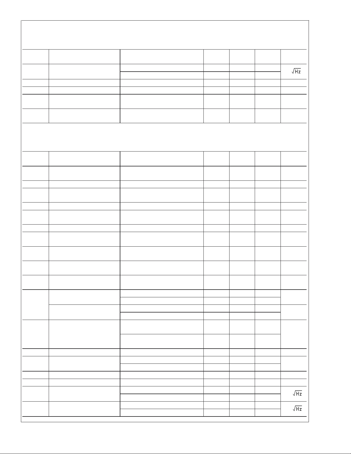
2.7V Electrical Characteristics (Continued)
Unless otherwise specified, all limits guaranteed for at TJ= 25˚C, V+= 2.7V, V−= 0V, VCM=VO=V+/2, and RF=2kΩ, and
=1kΩ to V+/2. Boldface limits apply at the temperature extremes.
R
L
Symbol Parameter Conditions Min
(Note 6)
i
n
Input-Referred Current Noise f = 100kHz 0.75
f = 1kHz 1.20
t
on
t
off
TH
SD
Turn-on Time (LMV118) 250 ns
Turn-off Time (LMV118) 560 ns
Shut-down Threshold
IS≤ 50µA 1.95 2.3 V
Typ
(Note 5)
Max
(Note 6)
pA/
(LMV118)
I
SD
Shutdown Pin Input Current
(Note 7) −20 µA
(LMV118)
5V Electrical Characteristics
Unless otherwise specified, all limits guaranteed for at TJ= 25˚C, V+= 5V, V−= 0V, VCM=VO=V+/2, and RF=2kΩ, and R
=1kΩ to V+/2. Boldface limits apply at the temperature extremes.
Symbol Parameter Conditions Min
(Note 6)
V
OS
TC V
I
B
I
OS
CMRR Common Mode Rejection
Input Offset Voltage 0V ≤ VCM≤1.7V
Input Offset Average Drift (Note 12)
OS
Input Bias Current (Note 7) −2.0
Input Offset Current 1 500 nA
V
Stepped from 0V to 3.8V 77 85 dB
CM
Ratio
+
PSRR Power Supply Rejection Ratio V
R
IN
Common Mode Input
=5Vto6VorV−= 0V to −1V 72 95 dB
Resistance
C
IN
Common Mode Input
Capacitance
CMVR Input Common-Mode Voltage
CMRR ≥ 50dB −0.3
Range
A
VOL
V
O
I
SC
Large Signal Voltage Gain VO= 1.5V to 3.5V 73
Output Swing High RL=1kΩ to V+/2 4.80 4.95
R
= 10kΩ to V+/2 4.98
L
Output Swing Low R
Output Short Circuit Current Sourcing to V
=1kΩ to V+/2 200 50
L
R
= 10kΩ to V+/2 20
L
−
VID= 200mV (Note 10)
Sinking to V
+
VID= −200mV (Note 10)
I
I
OUT
S
Output Current V
= 0.5V from rails
OUT
Supply Current Normal Operation 600 900
Shut-down Mode (LMV118) 10 50
SR Slew Rate (Note 8) A
BW −3dB BW A
e
n
Input -Referred Voltage Noise f = 100kHz 40
= +1, VO=1V
V
= +1, V
V
OUT
PP
= 200mV
PP
f = 1kHz 60
i
n
Input-Referred Current Noise f = 100kHz 0.75
f = 1kHz 1.20
−2.2
−0.1
70
35 45
35 43
Typ
(Note 5)
±
1
±
5 µV/C
Max
(Note 6)
±
5
±
6
−0.40 µA
3MΩ
2pF
4.0
85 dB
±
20 mA
40 V/µs
45 MHz
nV/
pA/
LMV116/LMV118
Units
L
Units
mV
V
V
mV
mA
µA
www.national.com3

5V Electrical Characteristics (Continued)
Unless otherwise specified, all limits guaranteed for at TJ= 25˚C, V+= 5V, V−= 0V, VCM=VO=V+/2, and RF=2kΩ, and R
=1kΩ to V+/2. Boldface limits apply at the temperature extremes.
Symbol Parameter Conditions Min
LMV116/LMV118
t
on
t
off
TH
Turn-on Time (LMV118) 210 ns
Turn-off Time (LMV118) 500 ns
SD
Shut-down Threshold
IS≤ 50µA 4.25 4.60 V
(Note 6)
(LMV118)
I
SD
Shutdown Pin Input Current
(Note 7) −20 µA
(LMV118)
±
5V Electrical Characteristics
Unless otherwise specified, all limits guaranteed for at TJ= 25˚C, V+= 5V, V−= −5V, VCM=VO= 0V, and RF=2kΩ, and R
=1kΩ to V+/2. Boldface limits apply at the temperature extremes.
Symbol Parameter Conditions Min
(Note 6)
V
OS
TC V
I
B
Input Offset Voltage −5V ≤ VCM≤ 1.7V
Input Offset Average Drift (Note 12)
OS
Input Bias Current (Note 7) −2.0
−2.2
I
OS
CMRR Common Mode Rejection
Input Offset Current 3 500 nA
V
Stepped from −5V to 3.5V 78 104 dB
CM
Ratio
+
PSRR Power Supply Rejection Ratio V
R
IN
Common Mode Input
=5Vto6VorV−= −5V to −6V 72 95 dB
Resistance
C
IN
Common Mode Input
Capacitance
CMVR Input Common-Mode Voltage
Range
A
VOL
Large Signal Voltage Gain VO= −2V to 2V 74
CMRR ≥ 50dB −5.3
−5.1
71
V
O
I
SC
Output Swing High RL=1kΩ 4.70 4.92 V
R
= 10kΩ 4.97
L
Output Swing Low R
Output Short Circuit Current Sourcing to 0V
=1kΩ −4.70 −4.93 mV
L
R
= 10kΩ −4.98
L
40 57 mA
= 200mV (Note 10)
V
ID
Sinking to 0V
40 54
VID= −200mV (Note 10)
I
I
OUT
S
Output Current V
= 0.5V from rails
OUT
Supply Current Normal Operation 600 900 µA
Shut-down Mode (LMV118) 15 50
SR Slew Rate (Note 8) A
BW −3dB BW A
e
n
Input -Referred Voltage Noise f = 100kHz 40
= +1, VO=1V
V
= +1, V
V
OUT
PP
= 200mV
PP
f = 1kHz 60
i
n
Input-Referred Current Noise f = 100kHz 0.75
f = 1kHz 1.20
t
on
t
off
Turn-on Time (LMV118) 200 ns
Turn-off Time (LMV118) 700 ns
Typ
(Note 5)
Typ
(Note 5)
±
1
Max
(Note 6)
Max
(Note 6)
±
±
±
5 µV/C
−0.40 µA
3MΩ
2pF
4.0 V
85 dB
±
20 mA
35 V/µs
45 MHz
L
Units
L
Units
5
mV
6
nV/
pA/
www.national.com 4

±
5V Electrical Characteristics (Continued)
Unless otherwise specified, all limits guaranteed for at TJ= 25˚C, V+= 5V, V−= −5V, VCM=VO= 0V, and RF=2kΩ, and R
=1kΩ to V+/2. Boldface limits apply at the temperature extremes.
Symbol Parameter Conditions Min
(Note 6)
TH
SD
Shut-down Threshold
IS≤ 50µA 4.25 4.60 V
Typ
(Note 5)
Max
(Note 6)
Units
(LMV118)
I
SD
Shutdown Pin Input Current
(Note 7) −20 µA
(LMV118)
Note 1: Absolute Maximum Ratings indicate limits beyond which damage to the device may occur. Operating Ratings indicate conditions for which the device is
intended to be functional, but specific performance is not guaranteed. For guaranteed specifications and the test conditions, see the Electrical Characteristics.
Note 2: Human body model, 1.5kΩ in series with 100pF.
Note 3: Applies to both single-supply and split-supply operation. Continuous short circuit operation at elevated ambient temperature can result in exceeding the
maximum allowed junction temperature of 150˚C.
Note 4: The maximum power dissipation is a function of T
P
=(T
D
J(MAX)-TA
Note 5: Typical values represent the most likely parametric norm.
Note 6: All limits are guaranteed by testing or statistical analysis.
Note 7: Positive current corresponds to current flowing into the device.
Note 8: Slew rate is the average of the rising and falling slew rates.
Note 9: Machine Model, 0Ω in series with 200pF.
Note 10: Short circuit test is a momentary test. See Note 11.
Note 11: Output short circuit duration is infinite for V
Note 12: Offset voltage average drift determined by dividing the change in V
Note 13: Guaranteed based on characterization only.
)/ θJA. All numbers apply for packages soldered directly onto a PC board.
<
6V at room temperature and below. For V
S
, θJA, and TA. The maximum allowable power dissipation at any ambient temperature is
J(MAX)
>
6V, allowable short circuit duration is 1.5ms.
at temperature extremes into the total temperature change.
OS
S
LMV116/LMV118
L
Connection Diagrams
SOT23-5 (LMV116) SOT23-6 (LMV118)
Top View
20080759
Top View
Ordering Information
Package Part Number Package Marking Transport Media NSC Drawing
5-Pin SOT-23
6-Pin SOT-23
LMV116MF
LMV116MFX 3k Units Tape and Reel
LMV118MF
LMV118MFX 3k Units Tape and Reel
AC1A
AD1A
1k Units Tape and Reel
1k Units Tape and Reel
20080760
MF05A
MF06A
www.national.com5

Typical Performance Characteristics At T
Supply Current vs. Supply Voltage Supply Current vs. V
LMV116/LMV118
= 25˚C. Unless otherwise specified.
J
CM
20080701
Gain and Phase vs. Frequency CMRR vs. Frequency
20080719
PSRR vs. Frequency Input Voltage Noise vs. Frequency
20080703
20080720
20080713
www.national.com 6
20080718

LMV116/LMV118
Typical Performance Characteristics At T
Input Current Noise vs. Frequency
20080717
Frequency Response for Various (AV) Large Signal Step Response
= 25˚C. Unless otherwise specified. (Continued)
J
Closed Loop Frequency Response for
Various Temperature
20080716
20080715
Offset Voltage vs. Common Mode Voltage
(A Typical Unit)
20080705
20080714
Offset Voltage vs. Common Mode Voltage
(A Typical Unit)
20080706
www.national.com7

Typical Performance Characteristics At T
= 25˚C. Unless otherwise specified. (Continued)
J
Offset Voltage vs. Common Mode Range (A Typical Unit) Input Bias Current vs. Supply Voltage
LMV116/LMV118
Input Bias Current vs. V
Sink Current vs. V
OUT
CM
20080707
20080708
Sink Current vs. V
Souce Current vs. V
20080702
OUT
20080710
OUT
20080709
www.national.com 8
20080712

LMV116/LMV118
Typical Performance Characteristics At T
Souce Current vs. V
Application Notes
CIRCUIT DESCRIPTION
The LMV116 and LMV118 are based on National Semiconductor’s proprietary VIP10 dielectrically isolated bipolar process.
The LMV116 and LMV118 architecture features the following:
Complimentary bipolar devices with exceptionally high f
•
(∼8GHz) even under low supply voltage (2.7V) and low
Collector bias current.
Common Emitter push-pull output stage capable of 20mA
•
output current (at 0.5V from the supply rails) while consuming only 600µA of total supply current. This architecture allows output to reach within milli-volts of either
supply rail at light loads.
Consistent performance from any supply voltage (2.7V-
•
10V) with little variation with supply voltage for the most
important specifications (e.g. BW, SR, I
OUT
, etc.)
MICRO-POWER SHUTDOWN
The LMV118 can be shutdown to save power and reduce its
supply current to less than 50µA guaranteed, by applying a
voltage to the SD pin. The SD pin is “active high” and needs
to be tied to V
<
20µA, 4pF equivalent capacitance) and a resistor to V
(
(≤20kΩ) will result in normal operation. Shutdown is guaranteed when SD pin is 0.4V or less from V
−
for normal operation. This input is low current
+
at any operating
supply voltage and temperature.
In the shutdown mode, essentially all internal device biasing
is turned off in order to minimize supply current flow and the
output goes into Hi-Z (high impedance) mode. Complete
device Turn-on and Turn-off times vary considerably relative
to the output loading conditions, output voltage, and input
impedance, but is generally limited to less than 1µs (see
tables for actual data).
During shutdown, the input stage has an equivalent circuit as
shown below in Figure 1
t
−
= 25˚C. Unless otherwise specified. (Continued)
J
OUT
20080711
20080756
FIGURE 1. LMV118 Equivalent Input in Shutdown Mode
As can be seen above, in shutdown, there may be current
flow through the internal diodes shown, caused by input
potential, if present. This current may flow through the external feedback resistor and result in an apparent output signal.
In most shutdown applications the presence of this output is
inconsequential. However, if the output is “forced” by another
device such as in a multiplexer, the other device will need to
conduct the current described in order to maintain the output
potential.
To keep the output at or near ground during shutdown when
there is no other device to hold the output low, a switch
(transistor) could be used to shunt the output to ground.
Figure 2 shows a circuit where a NPN bipolar is used to keep
the output near ground (∼80mV):
www.national.com9

Application Notes (Continued)
LMV116/LMV118
FIGURE 2. Active Pull-Down Schematic
Figure 3 shows the output waveform.
20080764
20080758
FIGURE 4. 2:1 MUX Operating off a 2.7V Single Supply
20080736
FIGURE 3. Output Held Low by Active Pull-Down
Circuit
If bipolar transistor power dissipation is not tolerable, the
switch could be by a N-channel enhancement mode MOSFET.
2.7V SINGLE SUPPLY 2:1 MUX
The schematic show in Figure 4 will function as a 2:1 MUX
operating on a single 2.7V power supply, by utilizing the
shutdown feature of the LMV118.
Figure 5 shows the MUX output when selecting between a
1MHz sine and a 250kHz triangular waveform.
20080735
FIGURE 5. 2:1 MUX Output
As can be seen in Figure 5, the output is well behaved and
there are no spikes or glitches due to the switching. Switching times are approximately around 500ns based on the time
when the output is considered “valid”.
www.national.com 10

Application Notes (Continued)
PRINTED CIRCUIT BOARD LAYOUT, COMPONENT
VALUES SELECTION, AND EVALUATION BOARDS
Generally, a good high-frequency layout will keep power
supply and ground traces away from the inverting input and
output pins. Parasitic capacitances on these nodes to
ground will cause frequency response peaking and possible
circuit oscillations (see Application Note OA-15 for more
information).
Another important parameter, is the component values selection. Choosing large valued external resistors, will effect
the closed loop behavior of the stage because of the interaction of these resistors with parasitic capacitances. These
capacitors could be inherent to the device or a by-product of
the board layout and component placement. Either way,
LMV116/LMV118
keeping the resistor values lower, will diminish this interaction. On the other hand, choosing very low value resistors
could load down nodes and will contribute to higher overall
power dissipation.
National Semiconductor suggests the following evaluation
boards as a guide for high frequency layout and as an aid in
device testing and characterization:
Device Package Evaluation
Board PN
LMV116 SOT23-5 CLC730068
LMV118 SOT23-6 CLC730116
These free evaluation boards are shipped when a device
sample request is placed with National Semiconductor.
www.national.com11

Physical Dimensions inches (millimeters) unless otherwise noted
LMV116/LMV118
5-Pin SOT23
NS Package Number MF05A
6-Pin SOT23
NS Package Number MF06A
www.national.com 12

Notes
LMV116/LMV118 Low Voltage, 45MHz, Rail-to-Rail Output Operational Amplifiers with Shutdown
Option
LIFE SUPPORT POLICY
NATIONAL’S PRODUCTS ARE NOT AUTHORIZED FOR USE AS CRITICAL COMPONENTS IN LIFE SUPPORT
DEVICES OR SYSTEMS WITHOUT THE EXPRESS WRITTEN APPROVAL OF THE PRESIDENT AND GENERAL
COUNSEL OF NATIONAL SEMICONDUCTOR CORPORATION. As used herein:
1. Life support devices or systems are devices or
systems which, (a) are intended for surgical implant
into the body, or (b) support or sustain life, and
whose failure to perform when properly used in
accordance with instructions for use provided in the
2. A critical component is any component of a life
support device or system whose failure to perform
can be reasonably expected to cause the failure of
the life support device or system, or to affect its
safety or effectiveness.
labeling, can be reasonably expected to result in a
significant injury to the user.
BANNED SUBSTANCE COMPLIANCE
National Semiconductor certifies that the products and packing materials meet the provisions of the Customer Products
Stewardship Specification (CSP-9-111C2) and the Banned Substances and Materials of Interest Specification
(CSP-9-111S2) and contain no ‘‘Banned Substances’’ as defined in CSP-9-111S2.
National Semiconductor
Americas Customer
Support Center
Email: new.feedback@nsc.com
Tel: 1-800-272-9959
www.national.com
National does not assume any responsibility for use of any circuitry described, no circuit patent licenses are implied and National reserves the right at any time without notice to change said circuitry and specifications.
National Semiconductor
Europe Customer Support Center
Fax: +49 (0) 180-530 85 86
Email: europe.support@nsc.com
Deutsch Tel: +49 (0) 69 9508 6208
English Tel: +44 (0) 870 24 0 2171
Français Tel: +33 (0) 1 41 91 8790
National Semiconductor
Asia Pacific Customer
Support Center
Email: ap.support@nsc.com
National Semiconductor
Japan Customer Support Center
Fax: 81-3-5639-7507
Email: jpn.feedback@nsc.com
Tel: 81-3-5639-7560
 Loading...