

National Semiconductor LMH1983 User Manual
LMH1983 Evaluation Kit Users Guide
LMH1983 Evaluation Kit Users Guide
Version 1.0
2/4/10
Page 1 of 25

LMH1983 Evaluation Kit Users Guide
INTRODUCTION
The LMH1983 Evaluation Kit (EVK) allows for the evaluation of the LMH1983
3G/HD/SD Video Clock Generator with Audio Clock. The LMH1983 device is
configured and controlled using National Semiconductor’s Analog Launch Pad (ALP)
software graphical user interface (GUI).
The GUI with the LMH1983 profile runs on Windows PC and can be used to program the
device’s control registers through the I2C interface. The Serial Peripheral Adapter (SPA)
board included in the kit provides I2C read/write control via the USB port of the PC with
the GUI. For more information about the GUI software and device register descriptions
and programming, please refer to the GUI software manual and LMH1983 datasheet.
Overview of LMH1983
The LMH1983 clock generator generates four video specific clocks. The device has four
PLLs in it.
PLL1 uses an external 27 MHz VCXO, and always generates a 27MHz reference
clock. This clock may be locked to an input reference which can be any of a
number of different types of reference – from video specific references to single
frequency reference signals.
PLL2 is dedicated to generating a 148.5 MHz clock (27 MHz * 5.5) , and is
locked to PLL1.
PLL3 is dedicated to generating a clock at 148.35 MHz (27 MHz * 5500/1001)
PLL4, by default is locked to PLL1, and generates a 24.576MHz clock which can
be used as an audio clock. PLL4 has a lot of versatility built in to it and can be
used for a broad variety of applications.
Page 2 of 25
LMH1983 Evaluation Kit Users Guide
p
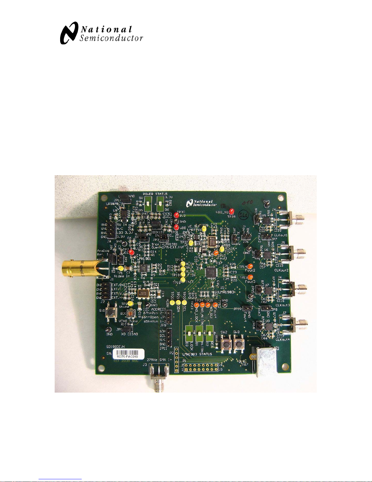
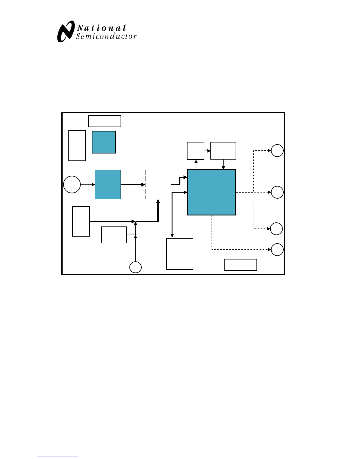
LMH1983 EVALUATION BOARD OVERVIEW
The following block diagram shows an overview of the LMH1983 evaluation board and
general location of the main features, which will be discussed in the following sections of
this manual.
Analog
Ref. In BNC
Power
Header
J1
J8
Power LEDs
LP
3878
LMH
1981
Syncs
Quad
2:1
MUX
HVF
in
LPF
uts
VCXO
X1
LMH1983
CLKout1
SMA
J4
CLKout2
SMA
J5
J2
EXT.HVF
VCXO
X2
CLK In
SMA
CLK
(VCXO
or SMA)
J3
USB
Port
J9
Status LEDs
CLKout3
SMA
J6
CLKout4
SMAs
J7
Applying power to the board:
The default configuration to apply power is to apply +5V across the top two pins on J8.
With a jumper on JP17, and on board LDO is used to generate the 3.3V rail that powers
the circuits on the evaluation board.
Alternately, JP17 may be removed, and a 3.3V rail may be applied directly to the bottom
two pins of J8.
Page 3 of 25
LMH1983 Evaluation Kit Users Guide
Installing the software:
The evaluation kit contains a CD which has the control software on it. Running the
program on the CD will install the software on your computer.
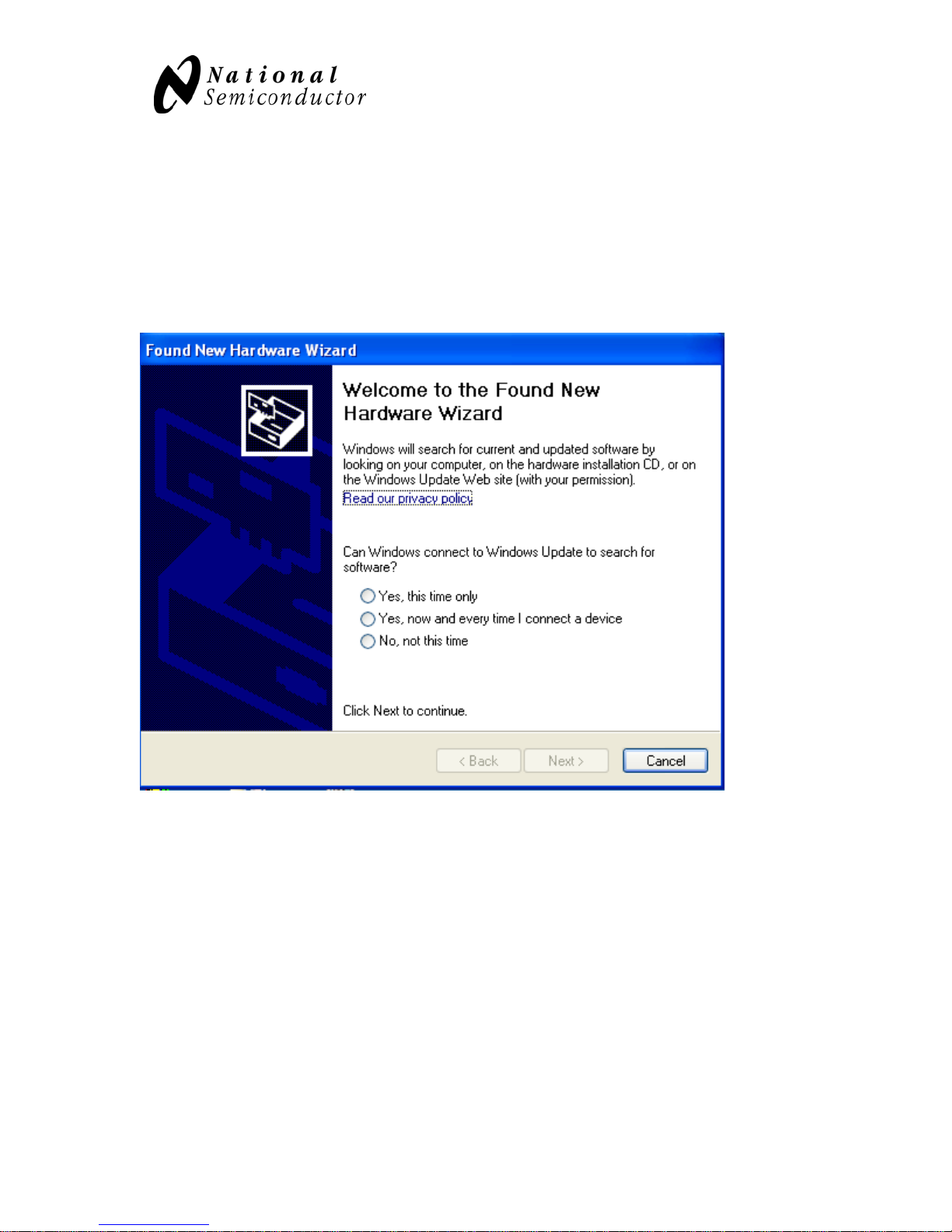
Apply power to the Evaluation Board, and then attach a USB cable between the computer
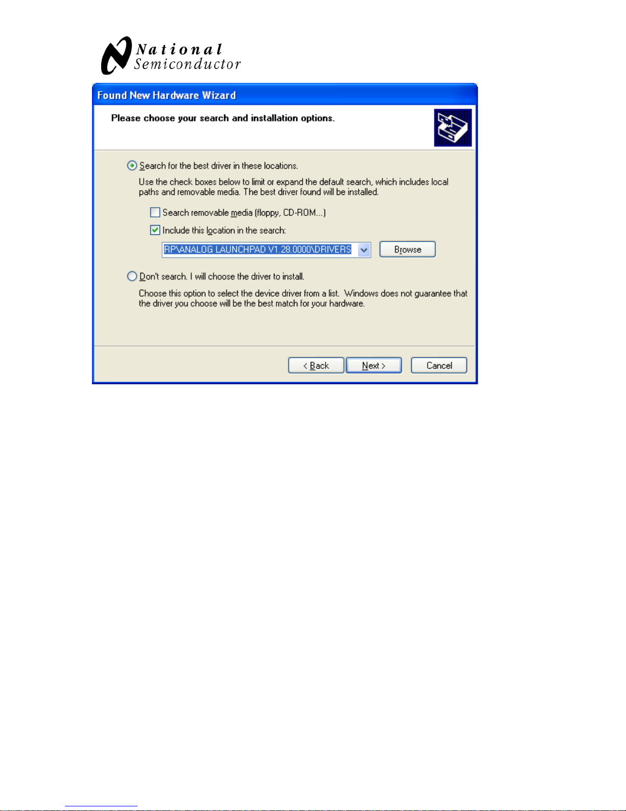
and the board. Windows will recognize the board and pop up the
When this window comes up, select ‘No, not this time’ and ‘Next>’
Page 4 of 25
LMH1983 Evaluation Kit Users Guide
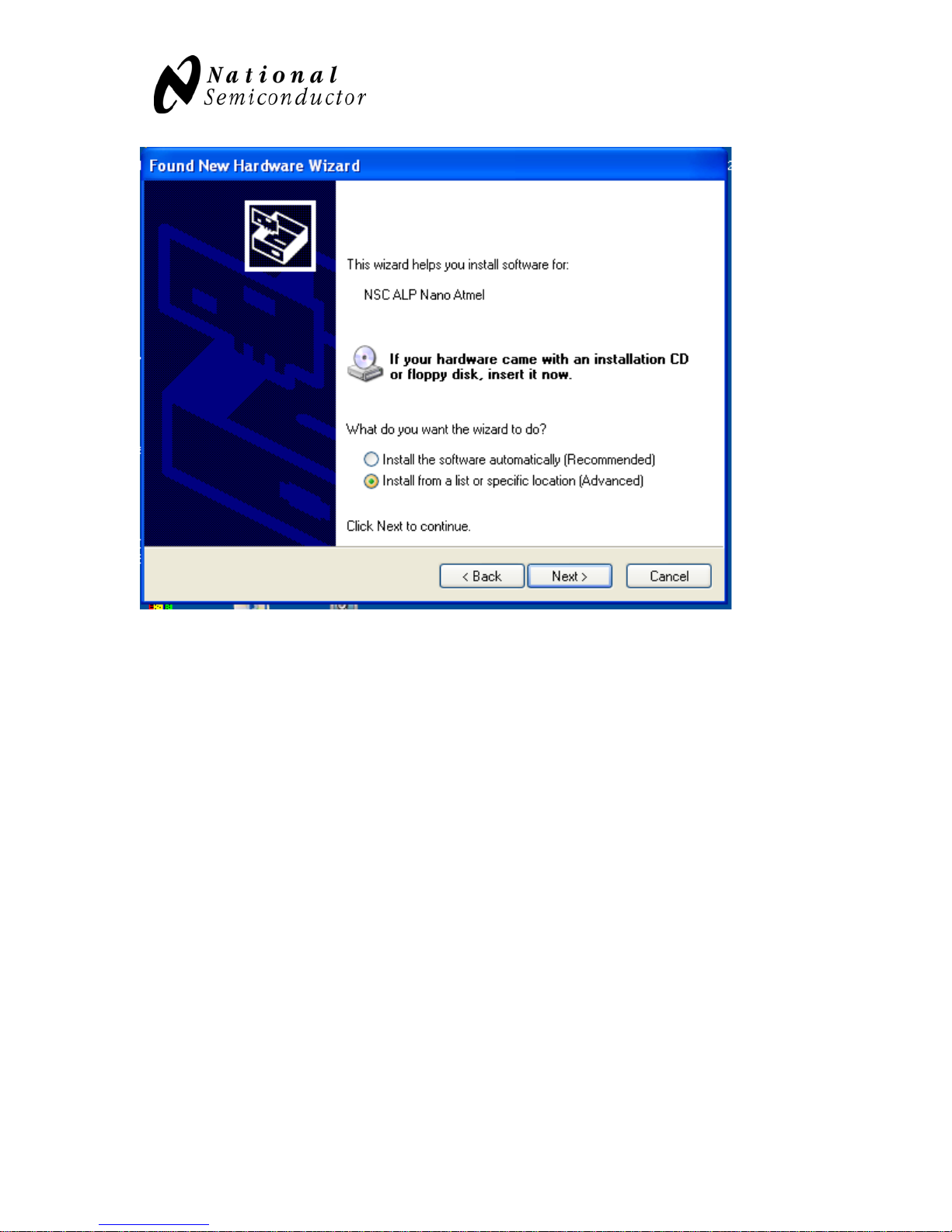
Select “Install from a list or specific location”
Page 5 of 25
LMH1983 Evaluation Kit Users Guide
Page 6 of 25
LMH1983 Evaluation Kit Users Guide
For the location, enter “C:\Program Files\National Semiconductor Corp\Analog
Launchpad Vxxx\DRIVERS” This directory was installed on your computer during the
ALP software installation.
The computer will warn you that the software has not passed Windows Logo Testing. Go
ahead and Continue Anyway.
The driver for the LMH1983 evaluation board will now be installed, and you can start the
ALP software.
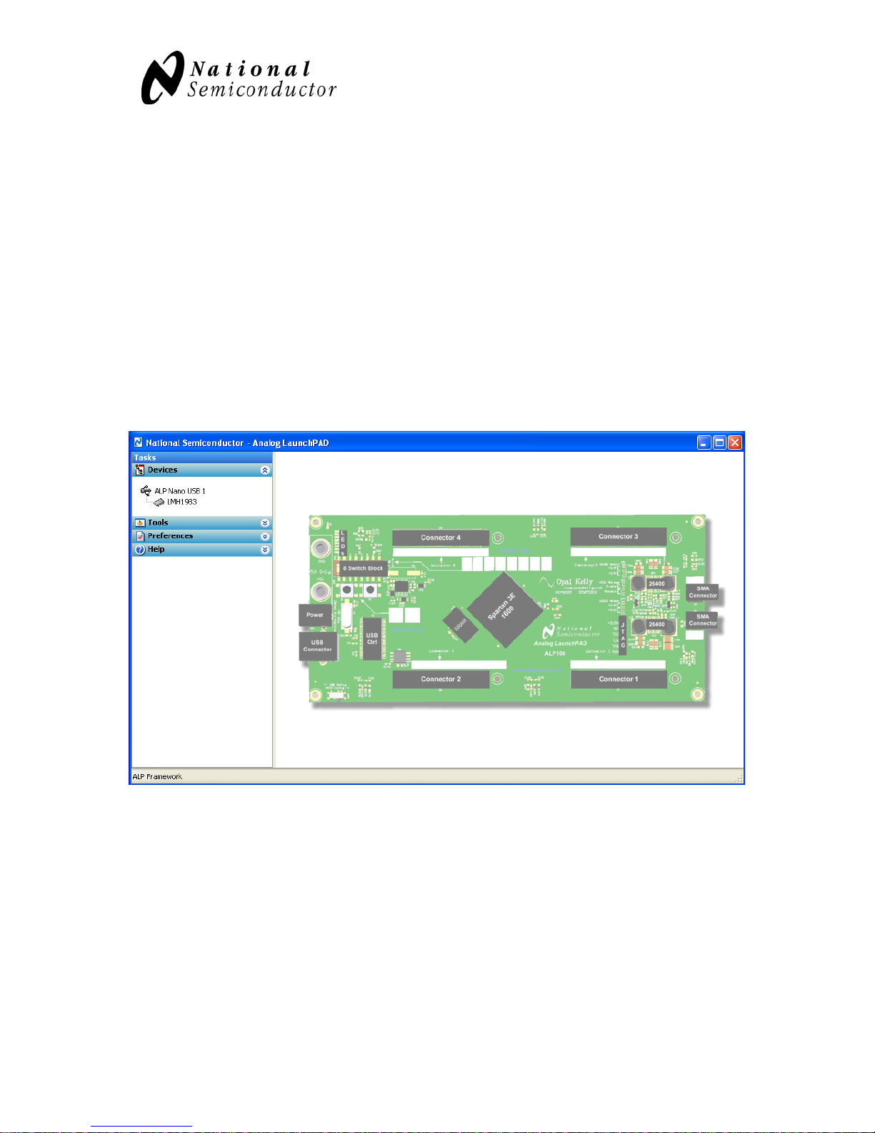
When you start the Analog LaunchPAD software, it should recognize the evaluation
board and the screen will look like the figure below.
If the board is not connected properly, or not powered up, the ALP software will start up
in a demo mode which will look like the normal mode, but will not control the board.
Once the startup screen appears, click on the LMH1983 icon on the left side of the
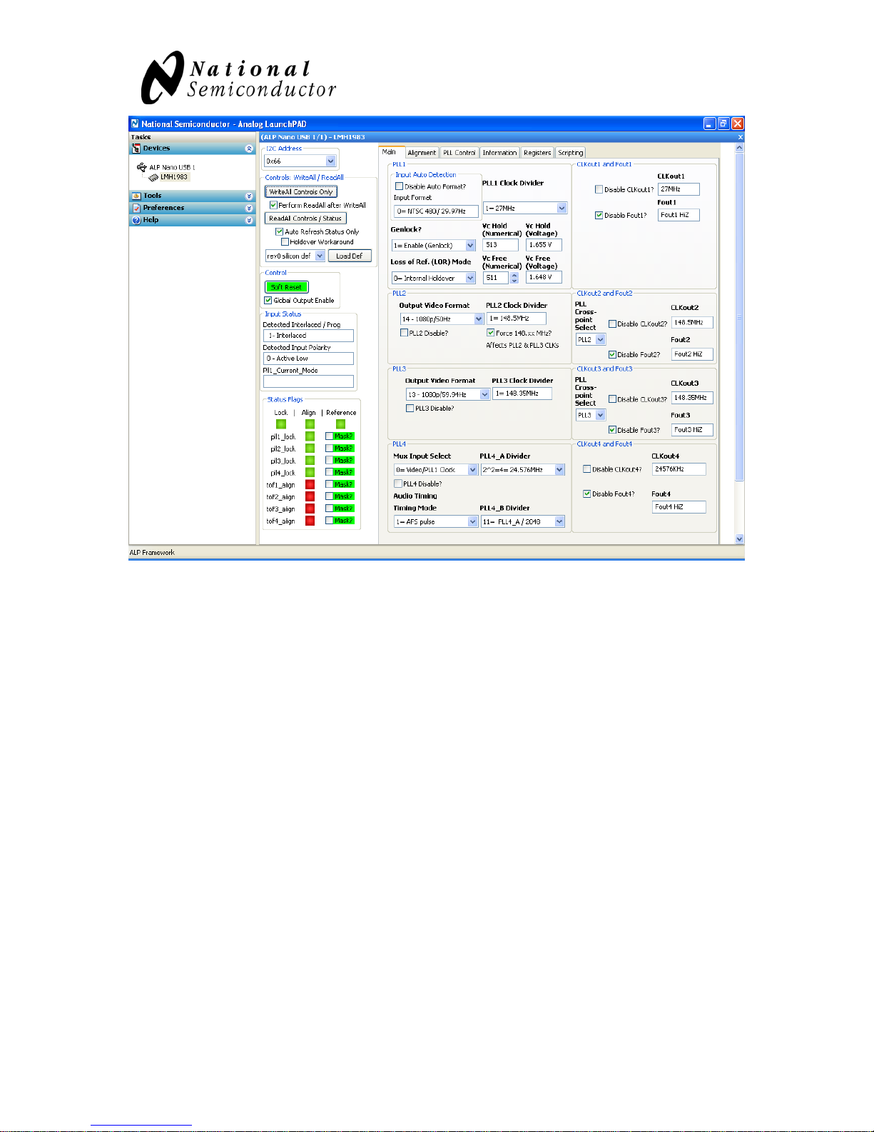
window, and this will bring up the GUI:
Page 7 of 25
LMH1983 Evaluation Kit Users Guide
The status indications on the GUI are only updated when the Read Controls/Status button
is clicked. To have continuous updates, click the checkbox ‘Auto Refresh Status’, I also
like to check the ‘Perform ReadAll after write’ box – this will update all of the status
controls whenever something is written. In some cases, writing to one register will result
in multiple things changing, and checking this button will make sure that everything is
kept updated.
There are several panels in the GUI - the first is the main control panel and allows for
basic control over the board. Also very useful is the Registers tab, which will allow for
detailed manipulation of the various registers in the LMH1983.
Page 8 of 25
 Loading...