

查询LM45B供应商
LM45B/LM45C
SOT-23 Precision Centigrade Temperature Sensors
General Description
The LM45 series are precision integrated-circuit temperature
sensors, whose output voltage is linearly proportional to the
Celsius (Centigrade) temperature. The LM45 does not require any external calibration or trimming to provide accura-
±
cies of
2˚C at room temperatureand±3˚C over a full−20to
+100˚C temperature range. Low cost is assured by trimming
and calibration at the wafer level. The LM45’s low output impedance, linear output, and precise inherent calibration
make interfacing to readout or control circuitry especially
easy. It can be used with a single power supply, or with plus
and minus supplies.As it draws only 120 µA from its supply,
it has very low self-heating, less than 0.2˚C in still air. The
LM45 is rated to operate over a −20˚ to +100˚C temperature
range.
Applications
n Battery Management
n FAX Machines
n Printers
n Portable Medical Instruments
n HVAC
n Power Supply Modules
n Disk Drives
n Computers
n Automotive
Features
n Calibrated directly in ˚ Celsius (Centigrade)
n Linear + 10.0 mV/˚C scale factor
±
n
3˚C accuracy guaranteed
n Rated for full −20˚ to +100˚C range
n Suitable for remote applications
n Low cost due to wafer-level trimming
n Operates from 4.0V to 10V
n Less than 120 µA current drain
n Low self-heating, 0.20˚C in still air
n Nonlinearity only
n Low impedance output, 20Ω for 1 mA load
±
0.8˚C max over temp
LM45B/LM45C SOT-23 Precision Centigrade Temperature Sensors
January 1999
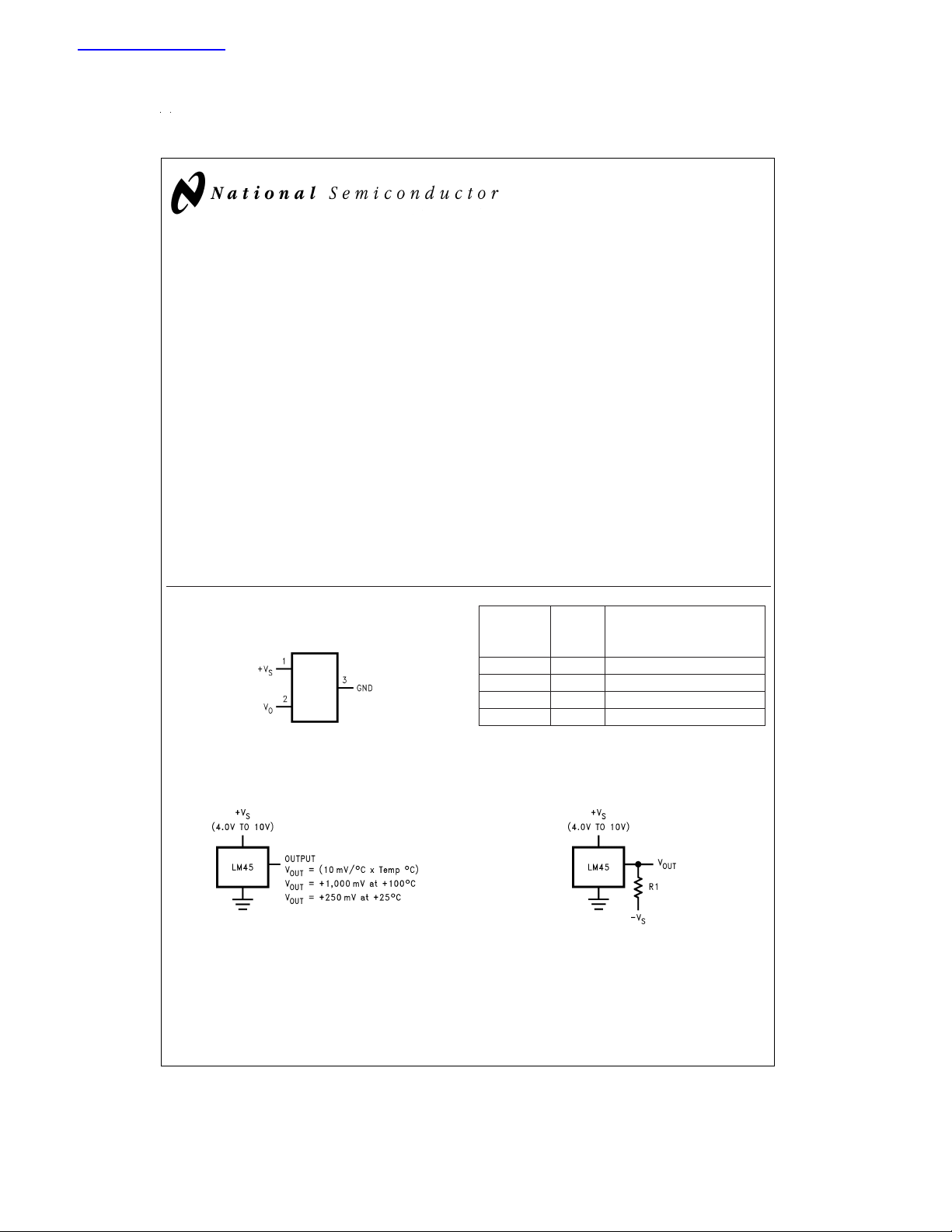
Connection Diagram
SOT-23
Top View
See NS Package Number MA03B
Typical Applications
FIGURE 1. Basic Centigrade Temperature
Sensor (+2.5˚C to +100˚C)
DS011754-1
DS011754-3
SOT-23
Order Device
Number Marking Supplied As
LM45BIM3 T4B 1000 Units on Tape and Reel
LM45BIM3X T4B 3000 Units on Tape and Reel
LM45CIM3 T4C 1000 Units on Tape and Reel
LM45CIM3X T4C 3000 Units on Tape and Reel
=
Choose R
=
V
OUT
V
OUT
/50 µA
−V
1
S
(10 mV/˚C x Temp ˚C)
=
+1,000 mV at +100˚C
=
+250 mV at +25˚C
=
−200 mV at −20˚C
FIGURE 2. Full-Range Centigrade
Temperature Sensor (−20˚C to +100˚C)
DS011754-4
© 1999 National Semiconductor Corporation DS011754 www.national.com

Absolute Maximum Ratings (Note 1)
Supply Voltage +12V to −0.2V
Output Voltage +V
Output Current 10 mA
Storage Temperature −65˚C to +150˚C
Lead Temperature:
SOT Package (Note 2):
+ 0.6V to −1.0V
S
Operating Ratings (Note 1)
Specified Temperature Range
(Note 4) T
LM45B, LM45C −20˚C to +100˚C
Operating Temperature Range
LM45B, LM45C −40˚C to +125˚C
Supply Voltage Range (+V
) +4.0V to +10V
S
MIN
to T
MAX
Vapor Phase (60 seconds) 215˚C
Infrared (15 seconds) 220˚C
ESD Susceptibility (Note 3):
Human Body Model
Machine Model
2000V
250V
Electrical Characteristics
Unless otherwise noted, these specifications apply for +V
specifications also apply from +2.5˚C to T
to T
T
MIN
; all other limits T
MAX
=
T
A
in the circuit of
MAX
=
+25˚C, unless otherwise noted.
J
=
+5Vdc and I
S
Figure 1
Parameter Conditions LM45B LM45C Units
Typical Limit Typical Limit
=
Accuracy T
(Note 6) T
Nonlinearity T
+25˚C
A
=
T
A
MAX
=
T
T
A
MIN
MIN≤TA≤TMAX
(Note 7)
Sensor Gain T
MIN≤TA≤TMAX
(Average Slope) +10.3 +10.3 mV/˚C (max)
Load Regulation (Note 8) 0≤I
Line Regulation +4.0V≤+V
≤ +1 mA
L
≤+10V
S
(Note 8)
Quiescent Current +4.0V≤+V
(Note 9) +4.0V≤+V
Change of Quiescent 4.0V≤+V
≤+10V, +25˚C 120 120 µA (max)
S
≤+10V 160 160 µA (max)
S
≤10V 2.0 2.0 µA (max)
S
Current (Note 9)
Temperature Coefficient +2.0 +2.0 µA/˚C
of Quiescent Current
Minimum Temperature In circuit of +2.5 +2.5 ˚C (min)
for Rated Accuracy
Long Term Stability (Note 10) T
Note 1: Absolute Maximum Ratings indicate limitsbeyond which damage to the device may occur. DC and AC electrical specifications do not apply when operating
the device beyond its rated operating conditions.
Note 2: See AN-450 “Surface Mounting Methods and Their Effect on Product Reliability” or the section titled “Surface Mount” found in a current National Semiconductor Linear Data Book for other methods of soldering surface mount devices.
Note 3: Human body model, 100 pF discharged through a 1.5 kΩ resistor. Machine model, 200 pF discharged directly into each pin.
Note 4: Thermal resistance of the SOT-23 package is 260˚C/W, junction to ambient when attached to a printed circuit board with 2 oz. foil as shown in
Note 5: Limits are guaranteed to National’s AOQL (Average Outgoing Quality Level).
Note 6: Accuracy is defined as the error between the output voltage and 10 mv/˚C times the device’s case temperature, at specified conditions of voltage, current,
and temperature (expressed in ˚C).
Note 7: Nonlinearity is defined as the deviation of the output-voltage-versus-temperature curve from the best-fit straight line, over the device’s rated temperature
range.
Note 8: Regulation is measured at constant junction temperature, using pulse testing with a low duty cycle. Changes in output due to heating effects can be com-
puted by multiplying the internal dissipation by the thermal resistance.
Note 9: Quiescent current is measured using the circuit of
Note 10: For best long-term stability, any precision circuit will give best results if the unit is aged at a warm temperature, and/or temperature cycled for at least 46
hours before long-term life test begins. This is especially true when a small (Surface-Mount) part is wave-soldered; allow time for stress relaxation to occur.
Figure 1
J
,I
=
, for 1000 hours
T
MAX
=
L
Figure 1
0
±
0.12
.
LOAD
for +V
=
+50 µA, in the circuit of
=
+5Vdc. Boldface limits apply for T
S
Figure 2
(Note 5) (Note 5)
±
2.0
±
3.0
±
3.0
±
0.8
±
3.0 ˚C (max)
±
4.0 ˚C (max)
±
4.0 ˚C (max)
±
0.8 ˚C (max)
+9.7 +9.7 mV/˚C (min)
±
±
±
35
0.80
1.2
±
0.12 ˚C
±
35 mV/mA
±
0.80 mV/V (max)
±
1.2 mV/V (max)
. These
A
=
T
J
(Limit)
(max)
Figure 3
=
.
www.national.com 2
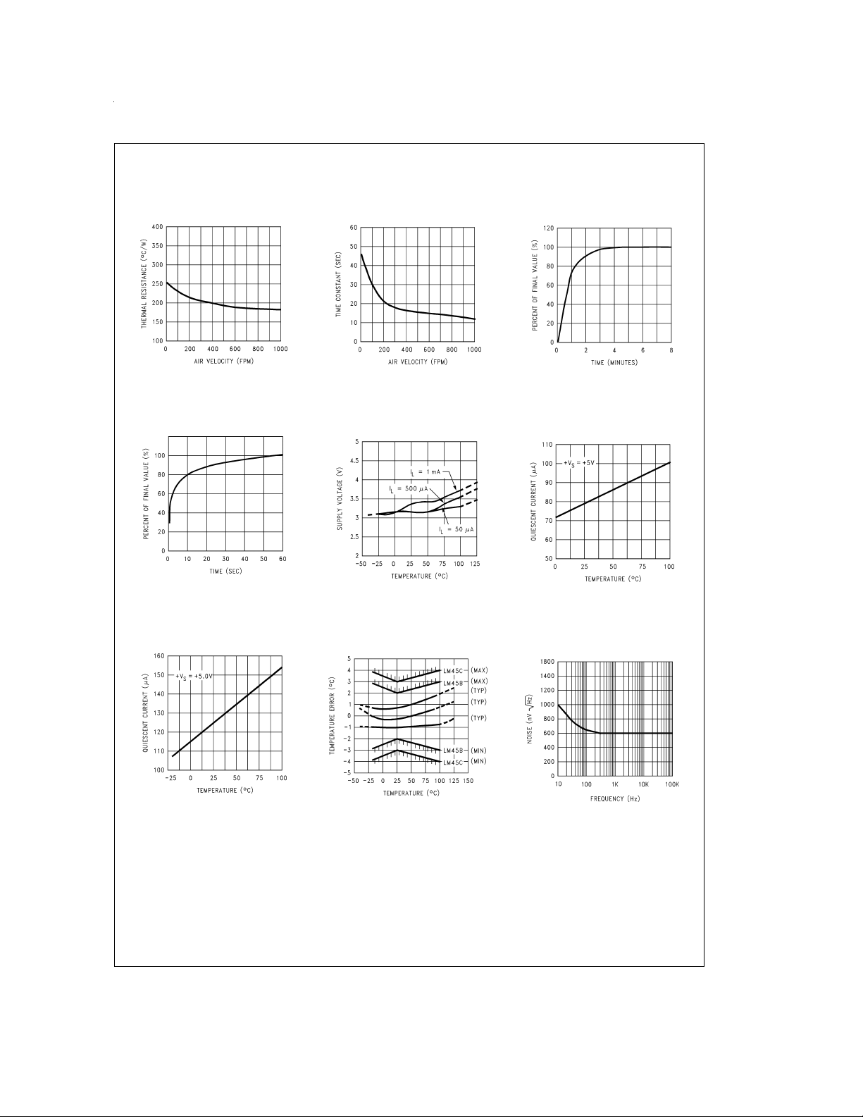
Typical Performance Characteristics To generate these curves the LM45 was mounted to a printed
circuit board as shown in
Figure 3
.
Thermal Resistance
Junction to Air
Thermal Response
in Stirred Oil Bath
with Heat Sink
DS011754-24
DS011754-27
Thermal Time Constant
Start-Up Voltage
vs Temperature
DS011754-25
DS011754-28
Thermal Response in Still Air
with Heat Sink (
Figure 3
)
DS011754-26
Quiescent Current
vs Temperature
(In Circuit of
Figure 1
)
DS011754-29
Quiescent Current
vs Temperature
(In Circuit of
Figure 2
)
DS011754-30
Accuracy vs Temperature
(Guaranteed)
DS011754-31
Noise Voltage
DS011754-32
www.national.com3

Typical Performance Characteristics To generate these curves the LM45 was mounted to a printed
circuit board as shown in
Supply Voltage
vs Supply Current
Figure 3
. (Continued)
Start-Up Response
DS011754-33
FIGURE 3. Printed Circuit Board Used for Heat Sink to Generate All Curves.
1
⁄2" Square Printed Circuit Board with 2 oz. Foil or Similar
Applications
The LM45 can be applied easily in the same way as other
integrated-circuit temperature sensors. It can be glued or cemented to a surface and its temperature will be within about
0.2˚C of the surface temperature.
This presumes that the ambient air temperature is almost the
same as the surface temperature; if the air temperature were
much higher or lower than the surface temperature, the actual temperature of the LM45 die would be at an intermediate
temperature between the surface temperature and the air
temperature.
To ensure good thermal conductivity the backside of the
LM45 die is directly attached to the GND pin. The lands and
traces to the LM45 will, of course, be part of the printed circuit board, which is the object whose temperature is being
measured. These printed circuit board lands and traces will
not cause the LM45s temperature to deviate from the desired temperature.
Alternatively, the LM45 can be mounted inside a sealed-end
metal tube, and can then be dipped into a bath or screwed
into a threaded hole in a tank.As with any IC, the LM45 and
accompanying wiring and circuits must be kept insulated and
dry, to avoid leakage and corrosion. This is especially true if
the circuit may operate at cold temperatures where condensation can occur.Printed-circuit coatings and varnishes such
DS011754-34
DS011754-23
as Humiseal and epoxy paints or dips are often used to insure that moisture cannot corrode the LM45 or its connections.
Temperature Rise of LM45 Due to Self-Heating
(Thermal Resistance)
SOT-23 SOT-23
no heat sink
*
small heat fin
**
Still air 450˚C/W 260˚C/W
Moving air 180˚C/W
*
Part soldered to 30 gauge wire.
*
Heat sink used is1⁄2” square printed circuit board with 2 oz. foil with part at-
*
tached as shown in
Figure 3
.
www.national.com 4

Typical Applications
CAPACITIVE LOADS
Like most micropower circuits, the LM45 has a limited ability
to drive heavy capacitive loads. The LM45 by itself is able to
drive 500 pF without special precautions. If heavier loads are
anticipated, it is easy to isolate or decouple the load with a
resistor; see
capacitance with a series R-C damper from output to
ground; see
Any linear circuit connected to wires in a hostile environment
can have its performance affected adversely by intense electromagnetic sources such as relays, radio transmitters, motors with arcing brushes, SCR transients, etc, as its wiring
can act as a receiving antenna and its internal junctions can
act as rectifiers. For best results in such cases, a bypass capacitor from V
75Ω in series with 0.2 or 1 µF from output to ground, as
shown in
FIGURE 4. LM45 with Decoupling from Capacitive Load
Figure 4
. Or you can improve the tolerance of
Figure 5
.
to ground and a series R-C damper such as
IN
Figure 5
, are often useful.
DS011754-8
DS011754-14
FIGURE 7. 4-to-20 mA Current Source (0˚C to +100˚C)
FIGURE 5. LM45 with R-C Damper
DS011754-12
FIGURE 6. Temperature Sensor,
Single Supply, −20˚C to +100˚C
DS011754-9
DS011754-15
FIGURE 8. Fahrenheit Thermometer
DS011754-16
FIGURE 9. Centigrade Thermometer (Analog Meter)
www.national.com5

Typical Applications (Continued)
FIGURE 10. Expanded Scale Thermometer
(50˚ to 80˚ Fahrenheit, for Example Shown)
FIGURE 11. Temperature To Digital Converter (Serial Output) (+128˚C Full Scale)
DS011754-17
DS011754-18
FIGURE 12. Temperature To Digital Converter (Parallel TRI-STATE®Outputs for
Standard Data Bus to µP Interface) (128˚C Full Scale)
www.national.com 6
DS011754-19

Typical Applications (Continued)
*=1%or 2%film resistor
-Trim R
-Trim R
-Trim R
-Example, V
=
for V
3.075V
B
B
=
for V
1.955V
C
C
=
for V
0.075V + 100mV/˚C x T
A
A
=
2.275V at 22˚C
A
DS011754-20
ambient
FIGURE 13. Bar-Graph Temperature Display (Dot Mode)
DS011754-21
FIGURE 14. LM45 With Voltage-To-Frequency Converter And Isolated Output
(2.5˚C to +100˚C; 25 Hz to 1000 Hz)
www.national.com7

Block Diagram
DS011754-22
www.national.com 8

Physical Dimensions inches (millimeters) unless otherwise noted
SOT-23 Molded Small Outline Transistor Package (M3)
Order Number LM45BIM3, LM45BIM3X, LM45CIM3 or LM45CIM3X
NS Package Number MA03B
LM45B/LM45C SOT-23 Precision Centigrade Temperature Sensors
LIFE SUPPORT POLICY
NATIONAL’S PRODUCTS ARE NOT AUTHORIZED FOR USE AS CRITICAL COMPONENTS IN LIFE SUPPORT
DEVICES OR SYSTEMS WITHOUT THE EXPRESS WRITTEN APPROVAL OF THE PRESIDENT AND GENERAL
COUNSEL OF NATIONAL SEMICONDUCTOR CORPORATION. As used herein:
1. Life support devices or systems are devices or
systems which, (a) are intended for surgical implant
into the body, or (b) support or sustain life, and
whose failure to perform when properly used in
accordance with instructions for use provided in the
2. A critical component is any component of a life
support device or system whose failure to perform
can be reasonably expected to cause the failure of
the life support device or system, or to affect its
safety or effectiveness.
labeling, can be reasonably expected to result in a
significant injury to the user.
National Semiconductor
Corporation
Americas
Tel: 1-800-272-9959
Fax: 1-800-737-7018
Email: support@nsc.com
www.national.com
National does not assume any responsibility for use of any circuitry described, no circuit patent licenses are implied and National reserves the right at any time without notice to change said circuitry and specifications.
National Semiconductor
Europe
Fax: +49 (0) 1 80-530 85 86
Email: europe.support@nsc.com
Deutsch Tel: +49 (0) 1 80-530 85 85
English Tel: +49 (0) 1 80-532 78 32
Français Tel: +49 (0) 1 80-532 93 58
Italiano Tel: +49 (0) 1 80-534 16 80
National Semiconductor
Asia Pacific Customer
Response Group
Tel: 65-2544466
Fax: 65-2504466
Email: sea.support@nsc.com
National Semiconductor
Japan Ltd.
Tel: 81-3-5639-7560
Fax: 81-3-5639-7507
 Loading...