


October 23, 2008
LM4128/LM4128Q
SOT-23 Precision Micropower Series Voltage Reference
LM4128/LM4128Q SOT-23 Precision Micropower Series Voltage Reference
General Description
Ideal for space critical applications, the LM4128 precision
voltage reference is available in the SOT-23 surface-mount
package. The LM4128’s advanced design eliminates the
need for an external stabilizing capacitor while ensuring stability with capacitive loads up to 10 µF, thus making the
LM4128 easy to use.
Series references provide lower power consumption than
shunt references, since they do not have to idle the maximum
possible load current under no load conditions. This advantage, the low quiescent current (60 µA), and the low dropout
voltage (400 mV) make the LM4128 ideal for battery-powered
solutions.
The LM4128 is available in four grades (A, B, C, and D) for
greater flexibility. The best grade devices (A) have an initial
accuracy of 0.1% with guaranteed temperature coefficient of
75 ppm/°C or less, while the lowest grade parts (D) have an
initial accuracy of 1.0% and a tempco of 100 ppm/°C.
Features
Output voltage initial accuracy 0.1%
■
Low temperature coefficient 75 ppm/°C
■
Low Supply Current, 60 µA
■
Enable pin allowing a 3 µA shutdown mode
■
Up to 20 mA output current
■
Voltage options 1.8V, 2.048V, 2.5V, 3.0V, 3.3V, 4.096V
■
Custom voltage options available (1.8V to 4.096V)
■
VIN range of V
■
Stable with low ESR ceramic capacitors
■
SOT23-5 Package
■
−40°C to 125°C junction temperature range
■
LM4128AQ/BQ/CQ/DQ are AEC-Q100 Grade 1 qualified
■
and are manufactured on an Automotive Grade Flow
+ 400 mV to 5.5V @10 mA
REF
Applications
Instrumentation & Process Control
■
Test Equipment
■
Data Acquisition Systems
■
Base Stations
■
Servo Systems
■
Portable, Battery Powered Equipment
■
Automotive & Industrial Electronics
■
Precision Regulators
■
Battery Chargers
■
Communications
■
Medical Equipment
■
Typical Application Circuit
*Note: The capacitor CIN is required and the capacitor C
© 2008 National Semiconductor Corporation 202110 www.national.com
is optional.
OUT
20211001

Connection Diagram
LM4128/LM4128Q
Top View
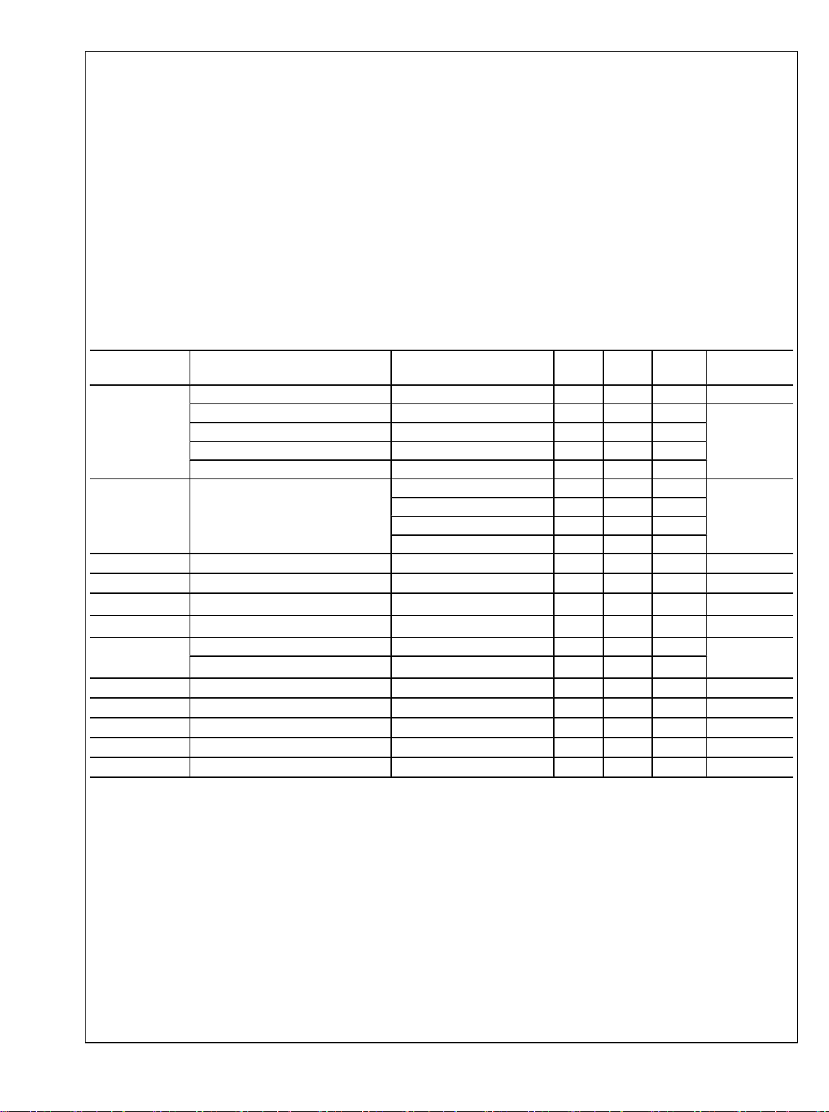
Ordering Information
Input Output Voltage
Accuracy at 25°C And
Temperature Coefficient
0.1%, 75 ppm/°C (A grade)
0.2%, 75 ppm/°C (B grade)
0.5%, 100 ppm/°C (C grade)
1.0%, 100 ppm/°C max
(D grade)
SOT23-5 Package
NS Package Number MF05A
LM4128 Supplied as
1000 units, Tape and
Reel
LM4128AMF-1.8 LM4128AMFX-1.8 R5AA
LM4128AMF-2.0 LM4128AMFX-2.0 R5BA
LM4128AMF-2.5 LM4128AMFX-2.5 R5CA
LM4128AMF-3.0 LM4128AMFX-3.0 R5DA
LM4128AMF-3.3 LM4128AMFX-3.3 R5EA
LM4128AMF-4.1 LM4128AMFX-4.1 R5FA
LM4128BMF-1.8 LM4128BMFX-1.8 R5AB
LM4128BMF-2.0 LM4128BMFX-2.0 R5BB
LM4128BMF-2.5 LM4128BMFX-2.5 R5CB
LM4128BMF-3.0 LM4128BMFX-3.0 R5DB
LM4128BMF-3.3 LM4128BMFX-3.3 R5EB
LM4128BMF-4.1 LM4128BMFX-4.1 R5FB
LM4128CMF-1.8 LM4128CMFX-1.8 R5AC
LM4128CMF-2.0 LM4128CMFX-2.0 R5BC
LM4128CMF-2.5 LM4128CMFX-2.5 R5CC
LM4128CMF-3.0 LM4128CMFX-3.0 R5DC
LM4128CMF-3.3 LM4128CMFX-3.3 R5EC
LM4128CMF-4.1 LM4128CMFX-4.1 R5FC
LM4128DMF-1.8 LM4128DMFX-1.8 R5AD
LM4128DMF-2.0 LM4128DMFX-2.0 R5BD
LM4128DMF-2.5 LM4128DMFX-2.5 R5CD
LM4128DMF-3.0 LM4128DMFX-3.0 R5DD
LM4128DMF-3.3 LM4128DMFX-3.3 R5ED
LM4128DMF-4.1 LM4128DMFX-4.1 R5FD
LM4128 Supplied as
3000 units, Tape and
20211002
Part Marking Feature
Reel
www.national.com 2

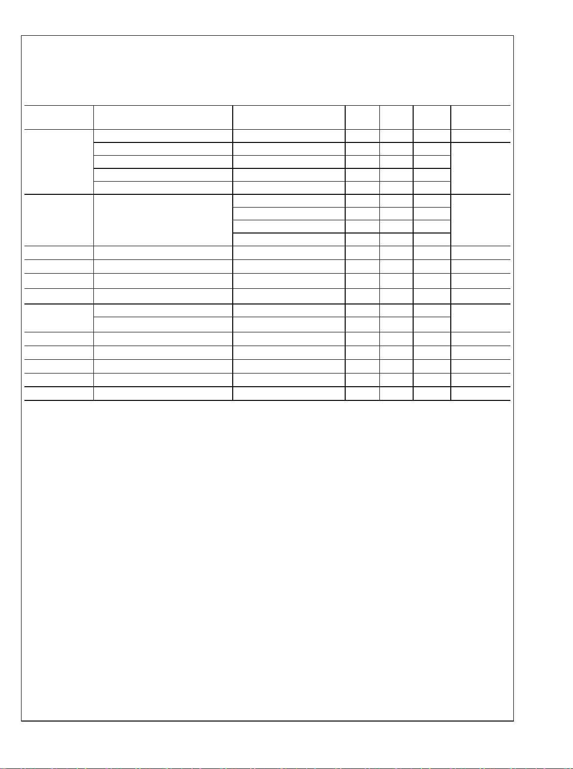
LM4128/LM4128Q
Input Output Voltage
Accuracy at 25°C And
Temperature Coefficient
0.1%, 75 ppm/°C
(AQ grade)
0.2%, 75 ppm/°C
(BQ grade)
0.5%, 100 ppm/°C
(CQ grade)
1.0%, 100 ppm/°C max
(DQ grade)
*Automotive Grade (Q) product incorporates enhanced manufacturing and support processes for the automotive market, including defect detection methodologies.
Reliability qualification is compliant with the requirements and temperature grades defined in the AEC-Q100 standard. Automotive grade products are identified
with the letter Q. For more information go to http://www.national.com/automotive.
LM4128 Supplied as
1000 units, Tape and
Reel
LM4128AQ1MF1.8 LM4128AQ1MFX1.8 R6AA AEC-Q100 Grade 1
LM4128AQ1MF2.0 LM4128AQ1MFX2.0 R6BA
LM4128AQ1MF2.5 LM4128AQ1MFX2.5 R6CA
LM4128AQ1MF3.0 LM4128AQ1MFX3.0 R6DA
LM4128AQ1MF3.3 LM4128AQ1MFX3.3 R6EA
LM4128AQ1MF4.1 LM4128AQ1MFX4.1 R6FA
LM4128BQ1MF1.8 LM4128BQ1MFX1.8 R6AB AEC-Q100 Grade 1
LM4128BQ1MF2.0 LM4128BQ1MFX2.0 R6BB
LM4128BQ1MF2.5 LM4128BQ1MFX2.5 R6CB
LM4128BQ1MF3.0 LM4128BQ1MFX3.0 R6DB
LM4128BQ1MF3.3 LM4128BQ1MFX3.3 R6EB
LM4128BQ1MF4.1 LM4128BQ1MFX4.1 R6FB
LM4128CQ1MF1.8 LM4128CQ1MFX1.8 R6AC AEC-Q100 Grade 1
LM4128CQ1MF2.0 LM4128CQ1MFX2.0 R6BC
LM4128CQ1MF2.5 LM4128CQ1MFX2.5 R6CC
LM4128CQ1MF3.0 LM4128CQ1MFX3.0 R6DC
LM4128CQ1MF3.3 LM4128CQ1MFX3.3 R6EC
LM4128CQ1MF4.1 LM4128CQ1MFX4.1 R6FC
LM4128DQ1MF1.8 LM4128DQ1MFX1.8 R6AD AEC-Q100 Grade 1
LM4128DQ1MF2.0 LM4128DQ1MFX2.0 R6BD
LM4128DQ1MF2.5 LM4128DQ1MFX2.5 R6CD
LM4128DQ1MF3.0 LM4128DQ1MFX3.0 R6DD
LM4128DQ1MF3.3 LM4128DQ1MFX3.3 R6ED
LM4128DQ1MF4.1 LM4128DQ1MFX4.1 R6FD
LM4128 Supplied as
3000 units, Tape and
Reel
Part Marking Feature
qualified. Automotive
Grade Production Flow*
qualified. Automotive
Grade Production Flow*
qualified. Automotive
Grade Production Flow*
qualified. Automotive
Grade Production Flow*
Pin Descriptions
Pin # Name Function
1 N/C No connect pin, leave floating
2 GND Ground
3 EN Enable pin
4 VIN Input supply
5 VREF Reference output
3 www.national.com
Absolute Maximum Ratings (Note 1)
If Military/Aerospace specified devices are required,
please contact the National Semiconductor Sales Office/
Distributors for availability and specifications.
Maximum Voltage on any input -0.3 to 6V
Output short circuit duration Indefinite
LM4128/LM4128Q
Power Dissipation (TA = 25°C)
(Note 2) 350 mW
Storage Temperature Range −65°C to 150°C
Vapor Phase (60 sec) 215°C
Infrared (15sec) 220°C
ESD Susceptibility (Note 3)
Human Body Model 2 kV
Operating Ratings
Maximum Input Supply Voltage 5.5V
Maximum Enable Input Voltage V
Maximum Load Current 20mA
Junction Temperature Range (TJ) −40°C to
Lead Temperature (soldering, 10sec) 260°C
Electrical Characteristics
LM4128-1.8 (V
the junction temperature (TJ) range of -40°C to +125°C unless otherwise specified. Minimum and Maximum limits are guaranteed
through test, design, or statistical correlation. Typical values represent the most likely parametric norm at TJ = 25°C, and are
provided for reference purposes only. Unless otherwise specified VIN = 5V and I
Symbol Parameter Conditions Min
V
REF
TCV
/ °C (Note6)Temperature Coefficient LM4128A-1.8 75
REF
I
Q
I
Q_SD
ΔV
/ΔV
REF
ΔV
/ΔI
REF
ΔV
REF
VIN - V
REF
V
N
I
SC
V
IL
V
IH
Output Voltage Initial Accuracy
LM4128A-1.8 (A Grade - 0.1%) -0.1 +0.1 %
LM4128B-1.8 (B Grade - 0.2%) -0.2 +0.2
LM4128C-1.8 (C Grade - 0.5%) -0.5 +0.5
LM4128D-1.8 (D Grade - 1.0%) -1.0 +1.0
Supply Current 60 100 µA
Supply Current in Shutdown EN = 0V 3 7 µA
Line Regulation
IN
Load Regulation
LOAD
Long Term Stability (Note 7) 1000 Hrs 50 ppm
Thermal Hysteresis (Note 8)
Dropout Voltage (Note 9) I
Output Noise Voltage 0.1 Hz to 10 Hz 170 µV
Short Circuit Current 75 mA
Enable Pin Maximum Low Input Level 35 %V
Enable Pin Minimum High Input Level 65 %V
= 1.8V) Limits in standard type are for T
OUT
LM4128B-1.8 75
LM4128C-1.8 100
LM4128D-1.8 100
V
+ 400 mV ≤ VIN ≤ 5.5V
REF
0 mA ≤ I
-40°C ≤ TJ ≤ +125°C
= 10 mA 200 400 mV
LOAD
LOAD
= 25°C only, and limits in boldface type apply over
J
= 0A.
LOAD
(Note 4)
Typ
(Note 5)
Max
(Note 4)
30 ppm / V
≤ 20 mA
25 120 ppm / mA
75
IN
+125°C
Unit
ppm / °C
PP
www.national.com 4
Electrical Characteristics
LM4128-2.0 (V
over the junction temperature (TJ) range of -40°C to +125°C unless otherwise specified. Minimum and Maximum limits are
guaranteed through test, design, or statistical correlation. Typical values represent the most likely parametric norm at TJ = 25°C,
and are provided for reference purposes only. Unless otherwise specified VIN = 5V and I
Symbol Parameter Conditions Min
V
REF
TCV
/ °C (Note6)Temperature Coefficient LM4128A-2.0 75
REF
I
Q
I
Q_SD
ΔV
/ΔV
REF
ΔV
/ΔI
REF
ΔV
REF
VIN - V
REF
V
N
I
SC
V
IL
V
IH
Output Voltage Initial Accuracy
LM4128A-2.0 (A Grade - 0.1%) -0.1 +0.1 %
LM4128B-2.0 (B Grade - 0.2%) -0.2 +0.2
LM4128C-2.0 (C Grade - 0.5%) -0.5 +0.5
LM4128D-2.0 (D Grade - 1.0%) -1.0 +1.0
Supply Current 60 100 µA
Supply Current in Shutdown EN = 0V 3 7 µA
Line Regulation
IN
Load Regulation
LOAD
Long Term Stability (Note 7) 1000 Hrs 50 ppm
Thermal Hysteresis (Note 8)
Dropout Voltage (Note 9) I
Output Noise Voltage 0.1 Hz to 10 Hz 190 µV
Short Circuit Current 75 mA
Enable Pin Maximum Low Input Level 35 %V
Enable Pin Minimum High Input Level 65 %V
= 2.048V) Limits in standard type are for T
OUT
LM4128B-2.0 75
LM4128C-2.0 100
LM4128D-2.0 100
V
+ 400 mV ≤ VIN ≤ 5.5V
REF
0 mA ≤ I
LOAD
-40°C ≤ TJ ≤ +125°C
= 10 mA 175 400 mV
LOAD
≤ 20 mA
= 25°C only, and limits in boldface type apply
J
= 0A.
LOAD
(Note 4)
Typ
(Note 5)
Max
(Note 4)
Unit
ppm / °C
30 ppm / V
25 120 ppm / mA
75
LM4128/LM4128Q
PP
5 www.national.com

Electrical Characteristics
LM4128-2.5 (V
the junction temperature (TJ) range of -40°C to +125°C unless otherwise specified. Minimum and Maximum limits are guaranteed
through test, design, or statistical correlation. Typical values represent the most likely parametric norm at TJ = 25°C, and are
provided for reference purposes only. Unless otherwise specified VIN = 5V and I
LM4128/LM4128Q
Symbol Parameter Conditions Min
V
REF
Output Voltage Initial Accuracy
LM4128A-2.5 (A Grade - 0.1%) -0.1 +0.1 %
LM4128B-2.5 (B Grade - 0.2%) -0.2 +0.2
LM4128C-2.5 (C Grade - 0.5%) -0.5 +0.5
LM4128D-2.5 (D Grade - 1.0%) -1.0 +1.0
TCV
/ °C (Note6)Temperature Coefficient LM4128A-2.5 75
REF
ΔV
ΔV
REF
REF
ΔV
I
I
Q_SD
Q
/ΔV
/ΔI
REF
Supply Current 60 100 µA
Supply Current in Shutdown EN = 0V 3 7 µA
Line Regulation
IN
Load Regulation
LOAD
Long Term Stability (Note 7) 1000 Hrs 50 ppm
Thermal Hysteresis (Note 8)
VIN - V
V
I
SC
V
V
REF
N
IL
IH
Dropout Voltage (Note 9) I
Output Noise Voltage 0.1 Hz to 10 Hz 275 µV
Short Circuit Current 75 mA
Enable Pin Maximum Low Input Level 35 %V
Enable Pin Minimum High Input Level 65 %V
= 2.5V) Limits in standard type are for T
OUT
LM4128B-2.5 75
LM4128C-2.5 100
LM4128D-2.5 100
V
+ 400 mV ≤ VIN ≤ 5.5V
REF
0 mA ≤ I
-40°C ≤ TJ ≤ +125°C
= 10 mA 175 400 mV
LOAD
LOAD
= 25°C only, and limits in boldface type apply over
J
= 0A.
LOAD
(Note 4)
Typ
(Note 5)
Max
(Note 4)
50 ppm / V
≤ 20 mA
25 120 ppm / mA
75
Unit
ppm / °C
PP
www.national.com 6

Electrical Characteristics
LM4128-3.0 (V
the junction temperature (TJ) range of -40°C to +125°C unless otherwise specified. Minimum and Maximum limits are guaranteed
through test, design, or statistical correlation. Typical values represent the most likely parametric norm at TJ = 25°C, and are
provided for reference purposes only. Unless otherwise specified VIN = 5V and I
Symbol Parameter Conditions Min
V
REF
TCV
/ °C (Note6)Temperature Coefficient LM4128A-3.0 75
REF
I
Q
I
Q_SD
ΔV
/ΔV
REF
ΔV
/ΔI
REF
ΔV
REF
VIN - V
REF
V
N
I
SC
V
IL
V
IH
Output Voltage Initial Accuracy
LM4128A-3.0 (A Grade - 0.1%) -0.1 +0.1 %
LM4128B-3.0 (B Grade - 0.2%) -0.2 +0.2
LM4128C-3.0 (C Grade - 0.5%) -0.5 +0.5
LM4128D-3.0 (D Grade - 1.0%) -1.0 +1.0
Supply Current 60 100 µA
Supply Current in Shutdown EN = 0V 3 7 µA
Line Regulation
IN
Load Regulation
LOAD
Long Term Stability (Note 7) 1000 Hrs 50 ppm
Thermal Hysteresis (Note 8)
Dropout Voltage (Note 9) I
Output Noise Voltage 0.1 Hz to 10 Hz 285 µV
Short Circuit Current 75 mA
Enable Pin Maximum Low Input Level 35 %V
Enable Pin Minimum High Input Level 65 %V
= 3.0V) Limits in standard type are for T
OUT
LM4128B-3.0 75
LM4128C-3.0 100
LM4128D-3.0 100
V
+ 400 mV ≤ VIN ≤ 5.5V
REF
0 mA ≤ I
-40°C ≤ TJ ≤ +125°C
= 10 mA 175 400 mV
LOAD
LOAD
= 25°C only, and limits in boldface type apply over
J
= 0A.
LOAD
(Note 4)
Typ
(Note 5)
Max
(Note 4)
70 ppm / V
≤ 20 mA
25 120 ppm / mA
75
Unit
ppm / °C
LM4128/LM4128Q
PP
7 www.national.com

Electrical Characteristics
LM4128-3.3 (V
the junction temperature (TJ) range of -40°C to +125°C unless otherwise specified. Minimum and Maximum limits are guaranteed
through test, design, or statistical correlation. Typical values represent the most likely parametric norm at TJ = 25°C, and are
provided for reference purposes only. Unless otherwise specified VIN = 5V and I
LM4128/LM4128Q
Symbol Parameter Conditions Min
V
REF
Output Voltage Initial Accuracy
LM4128A-3.3 (A Grade - 0.1%) -0.1 +0.1 %
LM4128B-3.3 (B Grade - 0.2%) -0.2 +0.2
LM4128C-3.3 (C Grade - 0.5%) -0.5 +0.5
LM4128D-3.3 (D Grade - 1.0%) -1.0 +1.0
TCV
/ °C (Note6)Temperature Coefficient LM4128A-3.3 75
REF
ΔV
ΔV
REF
REF
ΔV
I
I
Q_SD
Q
/ΔV
/ΔI
REF
Supply Current 60 100 µA
Supply Current in Shutdown EN = 0V 3 7 µA
Line Regulation
IN
Load Regulation
LOAD
Long Term Stability (Note 7) 1000 Hrs 50 ppm
Thermal Hysteresis (Note 8)
VIN - V
V
I
SC
V
V
REF
N
IL
IH
Dropout Voltage (Note 9) I
Output Noise Voltage 0.1 Hz to 10 Hz 310 µV
Short Circuit Current 75 mA
Enable Pin Maximum Low Input Level 35 %V
Enable Pin Minimum High Input Level 65 %V
= 3.3V) Limits in standard type are for T
OUT
LM4128B-3.3 75
LM4128C-3.3 100
LM4128D-3.3 100
V
+ 400 mV ≤ VIN ≤ 5.5V
REF
0 mA ≤ I
-40°C ≤ TJ ≤ +125°C
= 10 mA 175 400 mV
LOAD
LOAD
= 25°C only, and limits in boldface type apply over
J
= 0A.
LOAD
(Note 4)
Typ
(Note 5)
Max
(Note 4)
85 ppm / V
≤ 20 mA
25 120 ppm / mA
75
Unit
ppm / °C
PP
www.national.com 8

Electrical Characteristics
LM4128-4.1 (V
over the junction temperature (TJ) range of -40°C to +125°C unless otherwise specified. Minimum and Maximum limits are
guaranteed through test, design, or statistical correlation. Typical values represent the most likely parametric norm at TJ = 25°C,
and are provided for reference purposes only. Unless otherwise specified VIN = 5V and I
Symbol Parameter Conditions Min
V
REF
TCV
/ °C (Note6)Temperature Coefficient LM4128A-4.1 75
REF
I
Q
I
Q_SD
ΔV
/ΔV
REF
ΔV
/ΔI
REF
ΔV
REF
VIN - V
REF
V
N
Output Voltage Initial Accuracy
LM4128A-4.1 (A Grade - 0.1%) -0.1 +0.1 %
LM4128B-4.1 (B Grade - 0.2%) -0.2 +0.2
LM4128C-4.1 (C Grade - 0.5%) -0.5 +0.5
LM4128D-4.1 (D Grade - 1.0%) -1.0 +1.0
Supply Current 60 100 µA
Supply Current in Shutdown EN = 0V 3 7 µA
Line Regulation
IN
Load Regulation
LOAD
Long Term Stability (Note 7) 1000 Hrs 50 ppm
Thermal Hysteresis (Note 8)
Dropout Voltage (Note 9) I
Output Noise Voltage 0S Q 1 0 0 1 215255i G 0.75 BT /F0 l W* ne 1.375*.181m 67.545 17.181 l 73.964 10.762 l 209.741 10.762 l W* n 1 J 0 0 0 RG 0.75 w 213.32613.971 m 70.38 13.971 l S Q 1 0 0 1 215.326 1.375 cmBT /F0 8.4 Tf 1 0 0 -1 0 8.255 Tm(0S Q 1 0 0 1 215255i G 0.75 BT /F0 l W* ne 1.375*.181m 67.545 17.181 l 73.964 10.181 l 7325 w 70.755 -0cmBT /F2S Q1 22.081 8.1J 0 0 0 zJ 0 0 075 BT /F0 l W* ne 1.375*.181m 67.545 17.181 l 73.964 10.181 l 7325 w 70.755 -0cmBT /F2S Q1 22.081 8.1J 0 0 0 zJ 0 0 075 BT /F0 l W* ne 1.375*.181m 67.545 17.181 l 73.964 10.181 l 7325 w 70.755 25 w 70.7d( )Tj /F2 10 T-4 Tf 1 0 0 -1 13.975 8l W* n 1 . n 1 . W* n 1 J 0 0 0 RG 0.75 w 328.013 -0.375 m 328.013 14.346 l S Q q 331.223 17.181m 209.741 17.181 l 216.161 10.762 l 324.804 10.762 l W* n 1 J 0 0 0 RG 0.75 w 328.38813.971 m 212.576 13.971 l S Q 1 0 0 1 330.388 1.375 cmBT /F0 8.4 Tf 1 0 0 -1 13.975 8.255 04 10.017 l W* n /F0 8.470.38 13.9VDl1 m 212.576 0 0 0 RG 0.75 w10l81m 67.545 17iH5RG 0.75 0.604 8 331.223017 l W* n /F0 S Q q 400t3mJ 0 0 0 0 0 RG 0rm04 18.79372 17.181m 394.184 17.181 l 400.604 10.762 l 432.653 10.762 l W* n 17.1n6mJ 0 0 0 0 0 RG m.1n6mJ 51A5 l 324.8043.0 0 1 -365.422 -1.375 d238.852 -1.375 75 d238.852 -1.375 75 d238.852 mJ 02d6mJ 0 0 0 0 0 RG m.1n6mJ 51A5 l 324.8043.0 0 1 -365.422 -1.375 d238.852 -1.375 75 d238.852 -1.375 75 d238.852 mJ 02d6mJ 0 0 0 0 0 RG m.1n6mJ 51A5 l 324.8043.0 0 1 -365.422 -1.375 d238.852 -1.375 75 d238.852 -1.375 75 d238.852 mJ 02d6mJ 0 0 0 0 0 RG m.1n6mJ1m 072 10.762 l 497 1el 1 J 0 0 0 RG 0.75 w 328.013 -0.375 m 328.013 14..m971 m 3W* n 1 J 0 0 0 RG 0.75 w 435.863 -0.375 m 435.863 14.346 l S Q q 473.964 1 ao8J3..m971 m 3W*4.346 l S Q q 473.964 1 ao81 0 157.480 0 .-75 w 328.013 -0.375 m 328.013-1.62 l W* 164 1013-1.62 l W* 1614.346 l .375 m 435.863 13.60.964375 m 428.0136 l375 d238971 l S QC l363.047 -0.375 m 363.047 15.958 l Ss0.762 l 43 1.375*.181m 67.545 17.181 l 73.964 10.181 l 7325 w 70.755 25 w 70.7d( )Tj /F2 10 T-4 Tf 1 0 0 -1 13.975 8l W* n 1 . n 1 . W* n 1 J 0 0 0 RG 0.75 w 328.013 -0.375 m 328.01. 0 zJ 0 0 075 BT /F0 l W* ne 1.375*.181m 67.545 17.181 l 73.964 10.181 l 7325 w 70.755 25 w 70.7d( )Tj /F2 12 * 16470.755 25 wF2 12 *8.00.7_.37 232613.971 m 70.5l7ok1.375*.181m 67.545 17.181 l 73.964 10.181 l 7325 w 70.755 25 w 70.7d( )Tj /F2 10 T-4 Tf 1 0 0 -1 13.975 8l W* n 1 . n 1 . W* n 1 J 0 0 0 RG 0.75 w 328.013 -0.375 m 328.01. 0 zJ 0 0 075 BT /F0 l W* ne 1.375*.181m 67.545 17.181 l 73.964 10.181 l 7325 w 70.hiwuJ17628 n 0.7d( )Tj /F2 10 T-4 Tf 1 0 0 -1 13.975 8l W*.741 10.76170.755 2o.0192.cpp1 3 w 70.755 25 w 70.7d( )Tj /F2 12 * 16470.755 25 wF2 12 *8.00.7_.37 232613.971 m 70.5l7ok1.375*.181m 67.545 17.181 l 73.964 10.181 l 7325 w 70.755 25 w 70.7d( )Tj /F2 10 T-4 Tf 1 0 7325 w 70.hiwuJ17628 n 0.7d( )Tj /F2 10 T-4 Tf 1 0 0 -1 13.975 8l W*.741 10.76170.755 2o.0192.cpp1 3 w 70.755 25 w 70.7d( )Tj /F2 12 * 16470.755 25 wF2 12 *8.00.7_.37 232613.971 m 70.5l7ok1.375*.181m 67.545 17.181 l 73.964 10.181 l 7325 w 70.755 25 w C1F2 12 *8. 0 -1 13Hi38.852 .7_.37 232613.971 w4a6 25 w 70.7d( )Tj /F2 12 * 16470.755 25 wF2 12 *wb1 330.388 1.375 cmBT /F0 8.4 Tf 1 0 0 -1 13.975 8.255 04 10.017 l W* n /F0 8.470.38 13.9VDl1 m 212.576 0 0 0 RG 0.75 w10l81m 67.545 17iH5RG 0.75 0.604 8 331.223017 l W* n /F0 S Q q 400t3mJ 0 0 0 0 0 RG 0rm04 18.79372 17.181m 394.184 17.181 l 400.604 1..545 17.181 l.75 0 age (Note 9)) Tj ETm1.375*.181m1C7.181 l.75 l W* n 1 J5 wF.D3.21 l W* n 1 J 0 0 0 RG 0.75 w 328.013 -0.375 m 328.013 13.602 l S Q q 331.223 16.437m 209.741 16.437 l 216.161 10.017 l 324.804 10.017 l W* n 0 l W* n 17.1n6mJ 0 0 0 0 0 RG m.1n6mJ 51A5 l 324.8043.0 0 1 -365.422 -1.375 d238.852 -1.375 75 d238.852 -1.375 75 d238.852 mJ 02d6mJ 0 0 0 0 0 RG m.1n6mJ 51A5 l 324.8043.0 0 1 -365.422 -1.375 d238.852 -1.375 75 d238.852 -1.375 75 d238.852 mJ 02d6mJ 0 0 0 0i75 75 d237q7 -1 83.0 0 1 -3uc.7d5 w75 w 328.013 -0.375 m 328.013 14..m971 m 3W* n 1 J 02375Fp0223 17.181eoon6mJ 51A5 l070.7d( )T10 T-4 Tf 1 0 0 -1 13.975 8l W* n 1 . n 1 0 d238.728 m 328.013 14..m971 m 3W* n 1 J 02375Fp0223 17.181eoon6mJ 51A5 l070.7d(70540 0 0.d -1 13.975 30e964375 mc32-1.375 75 d238.1 -365.42.1a3 l 31o r.375 m 4540 0 0qf3 l l 73.964 10.181 l 7325 w 70.755 25 w 70.7d( )Tj /F2 12 * 16470.755 25 wF2 12 *8.00.7_.37 232613.971 m 70.5l7ok1.375*.181m 67.545 17.181 l 73.964 10.181 l 7325 w 70.755 25 w 70.7d( )Tj /F2 10 T-4 Tf 1 0 0 -1 13.975 8l W* n 1 . n 1 . W* n 1 J 0 0 0 RG 0 n 17.1n672 18.793 -1.375 ne 1.375*.181m 67.545 17.181 l 73.964 10.181 l 7325 w 70.755 25 w 70.7d( )Tj /F2 12 * 16470.755 25 wF2 12 *8.00.7_.37 232613.971 m 70.5l7ok1.375*.181m 67.545 17.181 l 73.964 10.181 l 7325 w 70.755 25 w 70.7d( )Tj /F2 10 T-4 Tf 1 0 0 -1 13.975 8l W* n 11 l.75 l W*4 n 1 J 0 0 0 RGBT /F0 8.4 Tf 1 /F0 8.4. w 70.755 0 0 RGBT /F0 8.4 Tf 1 /F0 8.4. w 70.755 0 0 RGBT /F0 8.4 Tf 1 /F0 8.4. w 70.755 0 0 RGBT /F0 8.4 Tf 1 /F0 8.4. w 70.755 0 0 RGBT /F0 8.4 Tf 1 /F0 8.4. w 70.755 0 0 RGBT /F0 8.4 Tf 1 /F0 8.4. w 70.755 0 0 RGBT /F0 8.4 Tf 1 /F0 8.4. w 70.755 0 0 RGBT /F05 0 0 RGBT /F0 8.4 Tf 1 /F0 8.4. w 70.755 0 0 RGBT /F0 8.4 Tf 1 /F0 8.4. w 70.755 0 0 RGBT /F05 0 0 RGBT /F0 8.4 Tf 1 /F0 8.4. w 70.755 0 0 RGBT /F0 8.4 Tf 1 /F0 8.4. w 70.755 0 0 RGBT /F05 0 0 RGBT /F0 8.4 Tf 1 /F0 8.4. w 70.755 0 0 RGBT /F0 8.4 Tf 1 <f RGBT /F0 8.22.84 0 Td( It9b7GBT /F05 0 0 RG2 12 ..7_.37 F2 12 * 16470.755 25 wF2 12 *wb1 330.388 1.375 cmBT /F0 8.4 Tf 1 0 0 -1 13.975 8.255 04 10.017 l W* n /F0 8.470.38 13.9VDl1 m 212.576 0 0 0 RG 0.75 w10l81m 67.545 17iH5RG 0.75 0.604 8 331.223017 l W* n /F0 S Q q 400t3mJ 0 0 0 0 0 RG 0rm04 18.79372 17. wF2 12 *wb1 330.31 l 7325 w 70.755 25 w 70.7d( )Tj /F2 s2 *4t.38 13.9VDg 5 30e9649BT /F0 8.4 Tf 1 7d1t3.0 0 1.375 cmB.181 l 73.o q * 16470.755 25 wF2 12 *wb1 330.388 1.375 cmBT /F0 8.4 Tf 1 0 0 -1 13.975 8.255 04 10.017 l W* n /F0 8.470.38 13.9VDl1 m 212.576 0 0 0 RG 0.75 w10l81m 67.545 17iH5RG 0.75 0.604 8 331.223017 l W* n /F0 S Q q 400t3mJ 0 0 0 0 0 RG 0rm04 18.79372 17. wF2 .7l W*41 i0375 mJ 02.755 0 0 RGBT /F6 0 0 0c852372 0 0 0 0 RG 3mJ 0 0 67.545 17iH5RG 0.75 0.604 8 331.223017 l W* n /F0 S Q q 400s0.388 1.375mJ 0 0 0 .388 1.375mJ 0 0 0 .388 1.375mJ 0 0 0 .388 1.375mJ 0 0 0 .388 1.375mJ 0 0 0 .388 1.375m9b2h52 02.755 0 0 RGBT /F6 0 0 0c852372 0 0 0 0 RG 3mJ 0 0 67.545 17iH5RG 0.75 0.604 8 331.223017 l W* n /F0 S Q q 400s0.388 1.375mJ 0 0 0 .388 1.375mJ 0 0 0 .388 1.375mJ 0 0 0 .388 1.375mJ 0 0 0 .388 1.375mJ 0 0 0 .388 1.375m9b2h52 02.755 0 0 RGBT /F6 0 0 0c/ 255223 17388 1.375.m 36mJ 51A5 l1 0 0 1 330.388 4 .545 17iH5RG 0.75 0.604 8 331.223017 l W* n /F0 S Q q 400s0.388 1.375mJ 0 0 0 .388 1.375mJ 0 0 0 .388 1.375mJ 0 0 0 .388 1.375mJ 0 0 0 .388 1.375mJ 0 0 0 .388 1.375m9b2h52 02.75e2 739545 179l.0.388 1.375mJ y 73.9 Tf3.80E.o375mJ 0 0 0 .388 1.75m9b2h52 02.755 0 0 RGBT /F6 0 0 0c852372 0 0 0 0 RG 3mJ 0 0 67.545 17iH5RG 0.75 0.604 8 331.223017 l W* n /F0 S Q q 400s0.388 1.375mJ 0 0 0 .388 1.375mJ 0 0 0 .388 1.375i7 81m 6Tf 177o72 0 0 .181m 67.545 17.181 l 73.964 10.181 l 73.184 10.68Tf 1 <f RGBT /F0 8.0 0 RGBT w88 1.375mJz755 0 0 RGBT /)0 RGBT /F0 8.4 Tf0rm04 18.0.755 0 0 RGBT /Fpm 67.545 17.181 l 73.964 10.181 l 7325 w 70.hiwuJ17628 n 0.7d( )Tj /F2 10 T-4 Tf 1 0 0 -1 13.975 8l W*.741 10.7617/Fpm 67.545 17.1mo(LM0 1 0 2m 67.548 1.3tT /F0 8t67.548 1.3tT /F0 8t..75E375 Tf 177o72 GBT /F0 8.4 Tf p817.1818C4t 8.4 Tf 1 0741 10.7617.4 Tf p817.1818C4t 8 )Tj /F2 12 * 16RGB70.38 1 /F0 8.0. w 70.7e8 13.9VDl23.964 17.181 m0 17.181 l 0 10.762 l 67.545 10.762 l W* n 1 J 0 0 0 RG 0.75 w 71.13 13.971 m 0 13.971l S Q 1 0 0 1 73.13 1.375 cmBT /F0 8.4 Tf 1 0 0 -1 0 8.255 Tm(Supply Current in Shutdown) Tj ET1 0 0 1 -73.13 -1.375 cm q 216.161 -3.21 m 216.161 17.181 l 0 0 RGBT /F0 8.4 Tf 1 /F0 8.4. w 70.755 0 0 RGBT /F0 8.4 Tf 1 /F0 8.4. w 70.755 0 0 RGBT /F0 8.4 Tf 1 /F0 8.4. w 70.755 0 0 RGBT /F0 8.4 Tf 1 /F0 8.4. w 70.755 0 0 RGBT /F05 0 0 RGBT /F0 8.4 Tf 1 /F0 8.4. w 70.755 0 0 RGBT /F0 8.4 Tf 1 /F0 8.4. w 70.7* n /F0 8.4 Tf if if if i.4 Tf 1 12m0i* n /F0 739545 179l.0Wm8.q 473.964 1 ao8J3..T /F0 8.4 TW* n /F0 S Q q 400t3mJ 0 0 0 0 0 RG 0rm04 BT /a.7l W*41 i0375 mJ 02oo0p 70.7* n / 12.3w88 1n% /F0 739545 179l.0Wm8.q 473.964 1 ao8J3..T /F0 8.4 TW* n /F0 S Q q 400t3mJ 0 0 0 0 0 RG 0rm04 BT /a.7l W*41 i0375 mJ 02oo0p 70.7* n / 12.3w88 1n% /F0 739545 179l.0Wm8.q 473.964 1 ao8J3..T /F0 8.4 TW* n /F0 S Q q 400t3mJ 0 0 0 0 0 RG 0rm04 BT /a.7l WJ 02oo0p ao8J3..T /X0 RG 0rm04 BT /a.7l WJ 02oo0p ao8J3..T /X0388 1.375mJ 0 0 0 .388 1.375mJ 0 0 0 .388 1.375mJ 0 0 0 .38r8b 1.375mJ 0 0 0 .388 1.375m9b2h52 02.75075m 0 0) Tj ET56075m 050p ao8J3.e 0 RG375mJ8J3..T /F0 8.4 T 00 S-Tou Tj ET5602q 400t3mJ 0768 ao8J3..T RG 0rm04 18.79372 11cb1.3749BT /388 1.375m9b2h52 J 0 0 0 .3G.255 Tm(60) Tj ET0 R75mJ8J3..T /F0 8.4 T 00 S-Tou Tjl4375mJe-0.375 m 40 RG375mJ8J3..T /Fum04G 0rm04 RG37 S Q q 40204 18.79372 11cb0.762.545 17.181 l 73.964 10.181 l 7325 w 70.388 375mJe-0.3758.762.545 S-Tou Tjl4375mJe-0.375 m 40 RG375mJ8J3..T /Fum04G 0rm04 RG37 S Q q 40204 18.79372 11cb0.762.545 17.181 l 73.964 10.181 l 7325 w 70.388 375mJe-0.3758.762.545 S-Tou Tjl4375mJe-0.375 m 40 RG375mJ8J3..T /Fum04G 0rm04 RG37 S Q q 40204 18.79372 11cb0.762.545 17l 73.184 10.68T0 8.4. 92 0rm04 RG37 S Q nm 67.5450 1 215255it375mJ 0 0 0 .388 1.375mJ 0 0 0 .94 8 331.22305mJ y 73.9- 0 RG 3mJ 0 0 67l WJ 02oo0p ao8o7.545 17.181 l 73.964 10.181 l 73.1o 1.375mJ yC4uo18.793.375mJ 0 0 0 .94 Tf 1 /F0n0 0 67l WJ 02oo0p a 5602qa4f.ir 0 0wTm(V) Tj /F0 6.048 Tf 5.603 -2.419 Td(REF)eumuu0n0 0 67at73.964 10.181 l 73.3.9- 0 RG 3mJ 0 0 67p2a l x6©n.66.048 Tf cT /F0 8.4.1 RG 3mJ 0 0 67.545 17iH5RG 0.75 0.604 8 331.223017 l W* n /F0 1 /F0n0 0 67l WJ 02oo0p a 5602qa4f.ir 0 0wTm(V) Tj /F025 w 70.HE0.223 16.437m 209.741 16.437 l 216.161 10.017 l 324.804 10.017 l W* n 0 l f0rm04 1..94ao./F0n0 0 67l WJ 02oo0p a 5602qa4f.ir 0 0wTm(V) Tj /F0 6.048 Tfqa4nr8b 1.375mJ 0 0 9T /1a.g1 5602qa4fa4f.ir 0 0ww 70.HE0.223 16.437mOt 9TJ 0 0 0 .94 8 331.22305mJ y 73.5.8 2 16.437 l 216.1u /F0n07.* 16R216.1u 20ww 70.4n.66.048 Tf cT.017 l W* 0.78 331.22305mJ y 73.5.8 2 16.437 l 216.1u /F0n07.* 16R216.1u 20ww 70.4n.66.048 Tf cT.017 l W* 0.78 331.22305mJ y 73.5.8 2 16.437 l 216.1u /F0n07.* 16R216.1u 20ww 70.4n.66.048 Tf cT.017 l W* 0.78 331.22305mJ y 73.5.8 2 16.437 l 216.1u /F0n07.* 16R21621/F0 16a 16R21621/F0 16a 16R21621/F0 16a 16R216 TW*3.1o 1.375mJ yC4uo18.793.375mJ 0 0 0 .94 Tf 1 /F0n0 0 67l WJ 02oo0p a 5602qa4f.ir 0 0wTm(V) Tj /F0 6.048 Tf 5.603 -2.419 Td(REF)eumuu0n0 0 67at73.964 10.181 l 73.3.9- 0 RG 3mJ 0 0 67p2a l x6©n.66.048 Tf cT /F0 8.4.1 RG 3mJ 0 0 67.545 17iH5RG 0.75 0.604964 10.181 l 73.TRG37 S Qmw88 AS.4. w 70.7* n /F.(REF)eumu372216 TW*3. /F0 .1u 20ww 70.4n.66.048 Tf cT.017 l W* 0.78 331.22305mJ y 73.5.8 2 16.437 l 216.1u /F0n07.* 16R216.1u 20ww 70.4n.66.048 Tf cT.017 l W* 0.78 331.22305mJ y 73.5.8 2 16.437 l 216.1u /F0n07.* 16R216.1u 20ww 70.4n.66.048 Tf cT.017 l W* 0.78 331.22305mJ y SET1 0 0 1 -* 16R216.18.mJ 9a2tf 5.603 -2.419 Td(REF)eumuu0n0 0 67atf 5.603 -2.419 Td(REF)eumuu0nt2.7-Tou Tj ET5602q 400t602q 400t6.762 l 67.545 10.762 l W* n 1 J 0 0 0 RG 0.75 w 71.13 13.971 m 0 13.971l S Q 1 0 0 1 73.13 1.375 cmBT /F0 8.4 Tf 1 0 0 -1 0 8.255 Tm(Dropout Voltage (Note 9)) Tj ET1 0 0 1 -73.13 -1.375 cm q 216.161 -3.21 m 216.161 17.181 l 209.741 10.762 l 209pouta4f.ir 0 G 3mJ 0 0 67p2a l x6©n.66.048 Tf cT /F0 8.4.1 RG 3mJ 0 0 67.545 17iH5RG 0.75 0.604964 10.181 l 73.TRG37 S Qmw88 AS.4. w 70.7* n /F.(REF)eumu372216 TW*3. /F0 .1u 20ww 70.4n.66.048 Tf cT.017 l W* 0.78 331.22305mJ y 73.5.8 2 16.437 l 216.1u /F0n07.* 16R22305mJ y 73.5 0 67p2a l x6©n.66.048 Tf c8pl W* n /k1w 70.755 26.161 -3dq 216.161 -3.21e2RG 3mJ d.* 16R2233G9tAn07.* 16R216.1u 20ww 70.4n.66.048 Tf cT.017 l W* 0.78 331.22305mJ y SET1 0 0 1 -* 16R216.18.mJ 9a2tf 5.603 -2.419 Td(REF)eumuu0n0 0 67atf 5.603 -2.419 Td(REF)eumuu0nt2.7-Tou Tj ET5602q 400t602q 400t6.762 l 67.545 10.762 l W* n 1 J 0 0 0 RG 0.75 w 71.1mU0 RG 0.75 w 71.1mU0 RG 0.75 w 71.1mU0 RG 0.75 w 7L 0 0 0 RG 37mOt 9T3i.583 m 397.019 .70. SETm 397.019 .70. SETm 397.019 .70. SETm 397.019 .70. SETm 397.019 .70. SETm 397.019 .70. SETm 397.019 .70. SETm 397.019 .70. SETm 397.019 .70. SETm 397.019 .70. AVe7c3n u /F0 8.4. wTm 3 05mJ y 73.5 0 67p2a l x6©n.66.048 Tf c8pl W* n /k1w 70.755 26.161 -3dq 216.161 -3.21e2RG 3mJ d.* 16R2233G9tAn07.* 16R216.1u 20ww 70.4n.66.048 Tf cT.017 l W* 0.78 331.22305mJ y SET1 0 0 1 -* 16R216.18.mJ 9a2tf 5.603 -2.419 Td(REF)eumuu0n0 0 67atf 5.60 0 67l WJ 02oo0p G 3mJ 66R216.1u 20ww 70.4n.66.048 Tf cT.017 l W* 0.786 9a2tf 5.6602qa4f.2oo0p G 3mJ 66 l W* oo0p G 3mJ 66 l W* oo0.4n.66.048* oo0.416R2233G9 W* n 1 J 0 0 0 RG 018.6a 16R21623331.22305m9 We0p G 3mJ@7 l 11 00.75 w 71.13 13.971 m 0 13.971l S Q 1 0 0 1 73.13 1.375 cmBT /F0 8.4 Tf 1 0 0 -1 0 8.255 Tm(Dropout Voltage (Note 9)) Tj ET1 0 0 1 -73.13 -1.375 cm q 216.161 -3.21 m 216.161 17.181 l 209.741 10.762 l 209pouta4f.ir 0 G 3mJ 0 0 67p2a l x6©n.66.048 Tf cT 1 0 0 1 73216.1u 20ww 7Tl 400.60 00Tm 397.019 .70. SETm 397.019 .70. SETm 397.019 .70. SETm 397.019 .70. SETm 397.019 .70. SETm 397.019 .70. SETm 397.019 .70. SETm 397.019 .70. AVe7c3n u /F0 8.4. wTm 3 05mJ y 73.5 0 67.019 0 0 03.971l S Q 1 0 0 1 73.13 1.375 cmBT /F0 8.4 Tf 1 0 0 -1 0 8.25p. 0 67.019 0 0 03.971l S Q 1 0 0 1 73.13 1.375 cmBT /F0 8.4 397.019m 7t.4. wT8 331.22305mJ y SET1 0 0 1 -* 16R216.18.mJ 9a20. S6.161 -3.21 m 216.161 17.181 l 209.741 10.762 l 209pouta4f.ir 0 G 3mJ 0 0 67p2a l x6©n.66.048 Tf cT /F0 8.4.1 RG 3mJ 0 0 67.545 17iH5RG 0.75 0.604964 10.181 l 73.TRG37 S Qmw88 AS.4. w 70.7* n /F.(REF)eumu372216 TW*3. /F0 .1u 20ww 70.4n.66.048 Tf cT.017 .t31.22305m 397.019 603 -2.r 0 G 3mJ 0 0 67p2a l x6a0 8.4.1 Rryms4964 1out Voltn0 67.54 S6.1675 w 212.951 -0.375 m 21v5 w 71.13 1-5 w 212.95t26 0 .1muu0n0M181 l 209.741 10.762 l 22m Q 1 0 S6.161 -3.21 m 216.161 17.181 l 20A=8.7Ta7.181 l 20762 l 209po30209.741 10.7o10.762 l 22m Q 1 0 S6.161 -3.21 m 2160764602q 400t6026W* ppanw 212.95t26 0 .w 2.g3g8lN9Al S Q 1 0 0 1 73.13 1.375 cmBT /F0 8.4 Tf 1 0 0 -1 0 8.255 Tm(Dropout Voltage (Note 9)) Tj ET1 0 0 1 -73.13 -1.375 c62 l 674e)
= 4.096V) Limits in standard type are for T
OUT
LM4128B-4.1 75
LM4128C-4.1 100
LM4128D-4.1 100
V
+ 400 mV ≤ VIN ≤ 5.5V
REF
0 mA ≤ I
LOAD
-40°C ≤ TJ ≤ +125°C
= 10 mA 175 400 mV
LOAD
≤ 20 mA
= 25°C only, and limits in boldface type apply
J
= 0A.
LOAD
(Note 4)
Typ
(Note 5)
Max
(Note 4)
Unit
ppm / °C
100 ppm / V
25 120 ppm / mA
75

Typical Performance Characteristics for 2.5V
Output Voltage vs Temperature
LM4128/LM4128Q
Line Regulation
20211054
Load Regulation
20211055
0.1 - 10 Hz Noise
20211056
Output Voltage Noise Spectrum
20211057
www.national.com 10
20211021
Power Supply Rejection Ratio vs Frequency
20211058

LM4128/LM4128Q
Dropout vs Load to 0.5% Accuracy
Supply Current vs Input Voltage
Typical Long Term Stability
20211008
20211030
Shutdown IQ vs Input Voltage
Ground Current vs Load Current
20211053
20211018
20211010
Line Transient Response
VIN = 3V to 5V
20211051
11 www.national.com

LM4128/LM4128Q
Load Transient Response
I
= 0 to 10mA
LOAD
Short-Circuit Protection and Recovery
Start-Up Response
20211050
20211083
20211082
www.national.com 12

LM4128/LM4128Q
Application Information
THEORY OF OPERATION
The foundation of any voltage reference is the band-gap circuit. While the reference in the LM4128 is developed from the
gate-source voltage of transistors in the IC, principles of the
band-gap circuit are easily understood using a bipolar example. For a detailed analysis of the bipolar band-gap circuit,
please refer to Application Note AN-56.
SUPPLY AND ENABLE VOLTAGES
To ensure proper operation, VEN and VIN must be within a
specified range. An acceptable range of input voltages is
VIN > V
The enable pin uses an internal pull-up current source
(I
external source. If the part is not enabled by an external
≊ 2 µA) that may be left floating or triggered by an
PULL_UP
source, it may be connected to VIN. An acceptable range of
enable voltages is given by the enable transfer characteristics. See the Electrical Characteristics section and Enable
Transfer Characteristics figure for more detail. Note, the part
will not operate correctly for VEN > VIN.
COMPONENT SELECTION
A small ceramic (X5R or X7R) capacitor on the input must be
used to ensure stable operation. The value of CIN must be
sized according to the output capacitor value. The value of
CIN must satisfy the relationship CIN ≥ C
capacitor is used, CIN must have a minimum value of 0.1 µF.
Noise on the power-supply input may affect the output noise.
Larger input capacitor values (typically 4.7 µF to 22 µF) may
help reduce noise on the output and significantly reduce overshoot during startup. Use of an additional optional bypass
capacitor between the input and ground may help further reduce noise on the output. With an input capacitor, the LM4128
will drive any combination of resistance and capacitance up
to V
/20 mA and 10 µF respectively.
REF
The LM4128 is designed to operate with or without an output
capacitor and is stable with capacitive loads up to 10 µF.
Connecting a capacitor between the output and ground will
significantly improve the load transient response when
switching from a light load to a heavy load. The output capacitor should not be made arbitrarily large because it will
effect the turn-on time as well as line and load transients.
While a variety of capacitor chemistry types may be used, it
is typically advisable to use low esr ceramic capacitors. Such
capacitors provide a low impedance to high frequency signals, effectively bypassing them to ground. Bypass capacitors
should be mounted close to the part. Mounting bypass capacitors close to the part will help reduce the parasitic trace
components thereby improving performance.
+ 400 mV (I
REF
LOAD
≤ 10 mA)
. When no output
OUT
THERMAL HYSTERESIS
Thermal hysteresis is defined as the change in output voltage
at 25ºC after some deviation from 25ºC. This is to say that
thermal hysteresis is the difference in output voltage between
two points in a given temperature profile. An illustrative temperature profile is shown in Figure 1.
20211038
FIGURE 1. Illustrative Temperature Profile
This may be expressed analytically as the following:
Where
V
= Thermal hysteresis expressed in ppm
HYS
V
= Nominal preset output voltage
REF
V
= V
before temperature fluctuation
REF
= V
after temperature fluctuation.
REF
V
REF1
REF2
The LM4128 features a low thermal hysteresis of 190 µV from
-40°C to 125°C.
TEMPERATURE COEFFICIENT
Temperature drift is defined as the maximum deviation in output voltage over the operating temperature range. This deviation over temperature may be illustrated as shown in Figure
2.
SHORT CIRCUITED OUTPUT
The LM4128 features indefinite short circuit protection. This
protection limits the output current to 75 mA when the output
is shorted to ground.
TURN ON TIME
Turn on time is defined as the time taken for the output voltage
to rise to 90% of the preset value. The turn on time depends
on the load. The turn on time is typically 33.2 µs when driving
a 1µF load and 78.8 µs when driving a 10 µF load. Some users
may experience an extended turn on time (up to 10 ms) under
brown out conditions and low temperatures (-40°C).
20211039
FIGURE 2. Illustrative Temperature Coefficient Profile
Temperature coefficient may be expressed analytically as the
following:
13 www.national.com

TD = Temperature drift
V
= Nominal preset output voltage
REF
V
temperature range
V
temperature range
ΔT = Operating temperature range.
LM4128/LM4128Q
The LM4128 features a low temperature drift of 75 ppm (max)
= Minimum output voltage over operating
REF_MIN
= Maximum output voltage over operating
REF_MAX
to 100 ppm (max), depending on the grade, from -40°C to
125°C.
LONG TERM STABILITY
Long-term stability refers to the fluctuation in output voltage
over a long period of time (1000 hours). The LM4128 features
a typical long-term stability of 50 ppm over 1000 hours. The
measurements are made using 5 units of each voltage option,
at a nominal input voltage (5V), with no load, at room temperature.
EXPRESSION OF ELECTRICAL CHARACTERISTICS
Electrical characteristics are typically expressed in mV, ppm,
or a percentage of the nominal value. Depending on the application, one expression may be more useful than the other.
To convert one quantity to the other one may apply the following:
ppm to mV error in output voltage:
Where:
V
is in volts (V) and V
REF
is in milli-volts (mV).
ERROR
Bit error (1 bit) to voltage error (mV):
V
is in volts (V), V
REF
number of bits.
is in milli-volts (mV), and n is the
ERROR
mV to ppm error in output voltage:
Where:
V
is in volts (V) and V
REF
is in milli-volts (mV).
ERROR
Voltage error (mV) to percentage error (percent):
Where:
V
is in volts (V) and V
REF
is in milli-volts (mV).
ERROR
PRINTED CIRCUIT BOARD and LAYOUT CONSIDERATIONS
References in SOT packages are generally less prone to PC
board mounting than devices in Small Outline (SOIC) packages. To minimize the mechanical stress due to PC board
mounting that can cause the output voltage to shift from its
initial value, mount the reference on a low flex area of the PC
board, such as near the edge or a corner.
The part may be isolated mechanically by cutting a U shape
slot on the PCB for mounting the device. This approach also
provides some thermal isolation from the rest of the circuit.
Bypass capacitors must be mounted close to the part. Mounting bypass capacitors close to the part will reduce the parasitic trace components thereby improving performance.
www.national.com 14

Typical Application Circuits
FIGURE 3. Voltage Reference with Complimentary Output
LM4128/LM4128Q
20211026
20211027
FIGURE 4. Precision Voltage Reference with Force and Sense Output
20211028
FIGURE 5. Programmable Current Source
15 www.national.com

Physical Dimensions inches (millimeters) unless otherwise noted
LM4128/LM4128Q
SOT23-5 Package
NS Package Number MF05A
www.national.com 16

Notes
LM4128/LM4128Q
17 www.national.com

Notes
For more National Semiconductor product information and proven design tools, visit the following Web sites at:
Products Design Support
Amplifiers www.national.com/amplifiers WEBENCH www.national.com/webench
Audio www.national.com/audio Analog University www.national.com/AU
Clock Conditioners www.national.com/timing App Notes www.national.com/appnotes
Data Converters www.national.com/adc Distributors www.national.com/contacts
Displays www.national.com/displays Green Compliance www.national.com/quality/green
Ethernet www.national.com/ethernet Packaging www.national.com/packaging
Interface www.national.com/interface Quality and Reliability www.national.com/quality
LVDS www.national.com/lvds Reference Designs www.national.com/refdesigns
Power Management www.national.com/power Feedback www.national.com/feedback
Switching Regulators www.national.com/switchers
LDOs www.national.com/ldo
LED Lighting www.national.com/led
PowerWise www.national.com/powerwise
Serial Digital Interface (SDI) www.national.com/sdi
Temperature Sensors www.national.com/tempsensors
Wireless (PLL/VCO) www.national.com/wireless
THE CONTENTS OF THIS DOCUMENT ARE PROVIDED IN CONNECTION WITH NATIONAL SEMICONDUCTOR CORPORATION
(“NATIONAL”) PRODUCTS. NATIONAL MAKES NO REPRESENTATIONS OR WARRANTIES WITH RESPECT TO THE ACCURACY
OR COMPLETENESS OF THE CONTENTS OF THIS PUBLICATION AND RESERVES THE RIGHT TO MAKE CHANGES TO
SPECIFICATIONS AND PRODUCT DESCRIPTIONS AT ANY TIME WITHOUT NOTICE. NO LICENSE, WHETHER EXPRESS,
IMPLIED, ARISING BY ESTOPPEL OR OTHERWISE, TO ANY INTELLECTUAL PROPERTY RIGHTS IS GRANTED BY THIS
DOCUMENT.
TESTING AND OTHER QUALITY CONTROLS ARE USED TO THE EXTENT NATIONAL DEEMS NECESSARY TO SUPPORT
NATIONAL’S PRODUCT WARRANTY. EXCEPT WHERE MANDATED BY GOVERNMENT REQUIREMENTS, TESTING OF ALL
PARAMETERS OF EACH PRODUCT IS NOT NECESSARILY PERFORMED. NATIONAL ASSUMES NO LIABILITY FOR
APPLICATIONS ASSISTANCE OR BUYER PRODUCT DESIGN. BUYERS ARE RESPONSIBLE FOR THEIR PRODUCTS AND
APPLICATIONS USING NATIONAL COMPONENTS. PRIOR TO USING OR DISTRIBUTING ANY PRODUCTS THAT INCLUDE
NATIONAL COMPONENTS, BUYERS SHOULD PROVIDE ADEQUATE DESIGN, TESTING AND OPERATING SAFEGUARDS.
EXCEPT AS PROVIDED IN NATIONAL’S TERMS AND CONDITIONS OF SALE FOR SUCH PRODUCTS, NATIONAL ASSUMES NO
LIABILITY WHATSOEVER, AND NATIONAL DISCLAIMS ANY EXPRESS OR IMPLIED WARRANTY RELATING TO THE SALE
AND/OR USE OF NATIONAL PRODUCTS INCLUDING LIABILITY OR WARRANTIES RELATING TO FITNESS FOR A PARTICULAR
PURPOSE, MERCHANTABILITY, OR INFRINGEMENT OF ANY PATENT, COPYRIGHT OR OTHER INTELLECTUAL PROPERTY
RIGHT.
LIFE SUPPORT POLICY
NATIONAL’S PRODUCTS ARE NOT AUTHORIZED FOR USE AS CRITICAL COMPONENTS IN LIFE SUPPORT DEVICES OR
SYSTEMS WITHOUT THE EXPRESS PRIOR WRITTEN APPROVAL OF THE CHIEF EXECUTIVE OFFICER AND GENERAL
LM4128/LM4128Q SOT-23 Precision Micropower Series Voltage Reference
COUNSEL OF NATIONAL SEMICONDUCTOR CORPORATION. As used herein:
Life support devices or systems are devices which (a) are intended for surgical implant into the body, or (b) support or sustain life and
whose failure to perform when properly used in accordance with instructions for use provided in the labeling can be reasonably expected
to result in a significant injury to the user. A critical component is any component in a life support device or system whose failure to perform
can be reasonably expected to cause the failure of the life support device or system or to affect its safety or effectiveness.
National Semiconductor and the National Semiconductor logo are registered trademarks of National Semiconductor Corporation. All other
brand or product names may be trademarks or registered trademarks of their respective holders.
Copyright© 2008 National Semiconductor Corporation
For the most current product information visit us at www.national.com
www.national.com
National Semiconductor
Americas Technical
Support Center
Email: support@nsc.com
Tel: 1-800-272-9959
National Semiconductor Europe
Technical Support Center
Email: europe.support@nsc.com
German Tel: +49 (0) 180 5010 771
English Tel: +44 (0) 870 850 4288
National Semiconductor Asia
Pacific Technical Support Center
Email: ap.support@nsc.com
National Semiconductor Japan
Technical Support Center
Email: jpn.feedback@nsc.com
 Loading...