

查询LM4041AIM3X-1.2供应商
LM4041
Precision Micropower Shunt Voltage Reference
LM4041 Precision Micropower Shunt Voltage Reference
January 2001
General Description
Ideal for space critical applications, the LM4041 precision
voltage reference is available in the sub-miniature SC70 and
SOT-23 surface-mount packages. The LM4041’s advanced
design eliminates the need for an external stabilizing capacitor while ensuring stability with any capacitive load, thus
making the LM4041 easy to use. Further reducing design
effort is the availability of a fixed (1.225V) and adjustable
reverse breakdown voltage. The minimum operating current
is 60 µA for the LM4041-1.2 and the LM4041-ADJ. Both
versions have a maximum operating current of 12 mA.
The LM4041 utilizes fuse and zener-zap reverse breakdown
or reference voltage trim during wafer sort to ensure that the
prime parts have an accuracy of better than
(A grade) at 25˚C. Bandgap reference temperature drift curvature correction and low dynamic impedance ensure stable
reverse breakdown voltage accuracy over a wide range of
operating temperatures and currents.
±
0.1%
Features
n Small packages: SOT-23, TO-92, and SC70
n No output capacitor required
n Tolerates capacitive loads
n Reverse breakdown voltage options of 1.225V and
adjustable
Key Specifications (LM4041-1.2)
j
Output voltage tolerance
±
(A grade, 25˚C)
j
Low output noise
(10 Hz to 10kHz) 20µV
j
Wide operating current range 60µA to 12mA
j
Industrial temperature range −40˚C to +85˚C
j
Extended temperature range −40˚C to +125˚C
j
Low temperature coefficient 100 ppm/˚C (max)
0.1%(max)
Applications
n Portable, Battery-Powered Equipment
n Data Acquisition Systems
n Instrumentation
n Process Control
n Energy Management
n Automotive
n Precision Audio Components
rms
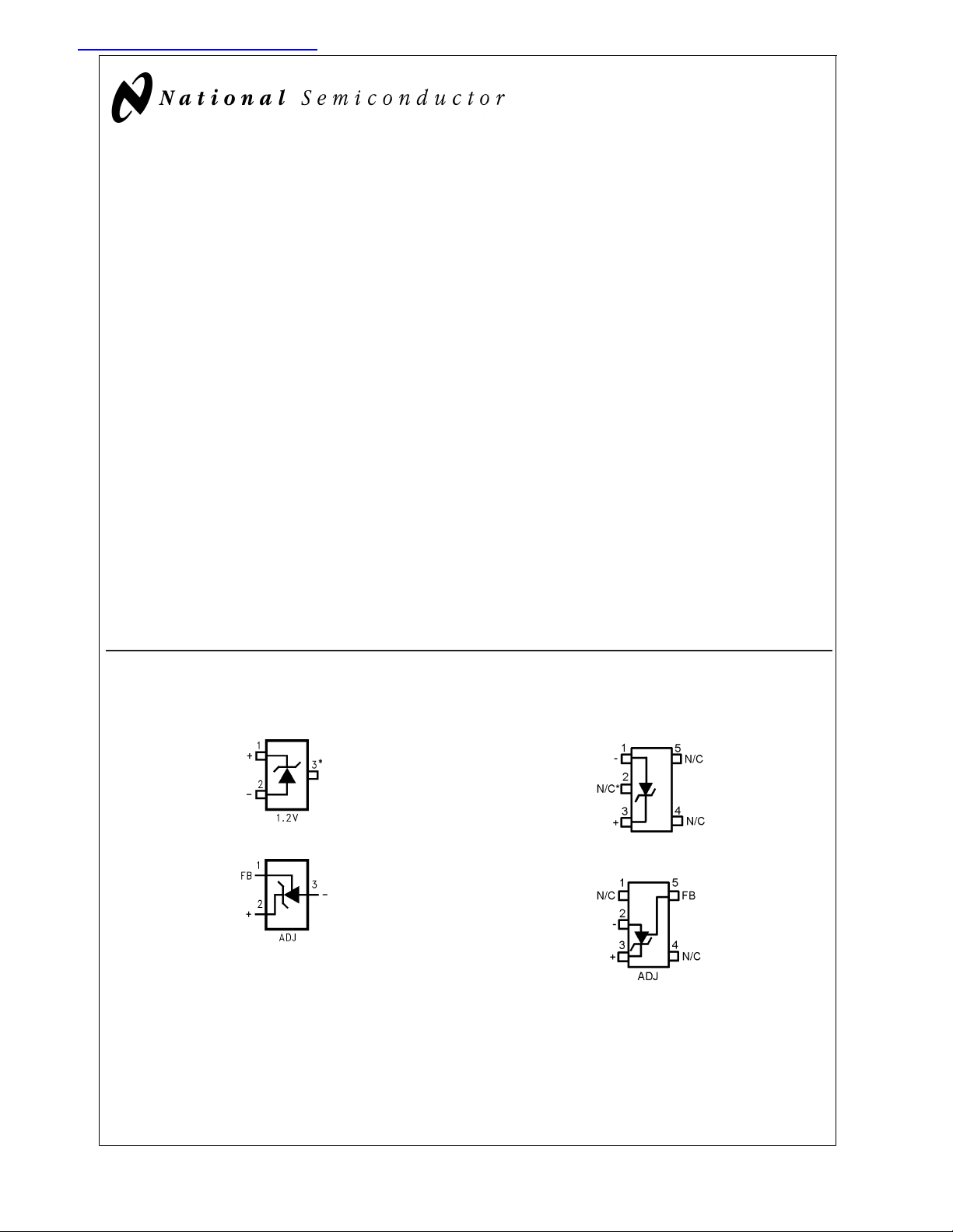
Connection Diagrams
SOT-23
DS011392-1
*This pin must be left floating or connected to pin 2.
DS011392-40
Top View
See NS Package Number MF03A
(JEDEC Registration TO-236AB)
SC-70
DS011392-46
*This pin must be left floating or connected to pin 1.
DS011392-47
Top View
See NS Package Number MAA05A
© 2001 National Semiconductor Corporation DS011392 www.national.com

Connection Diagrams (Continued)
LM4041
TO-92
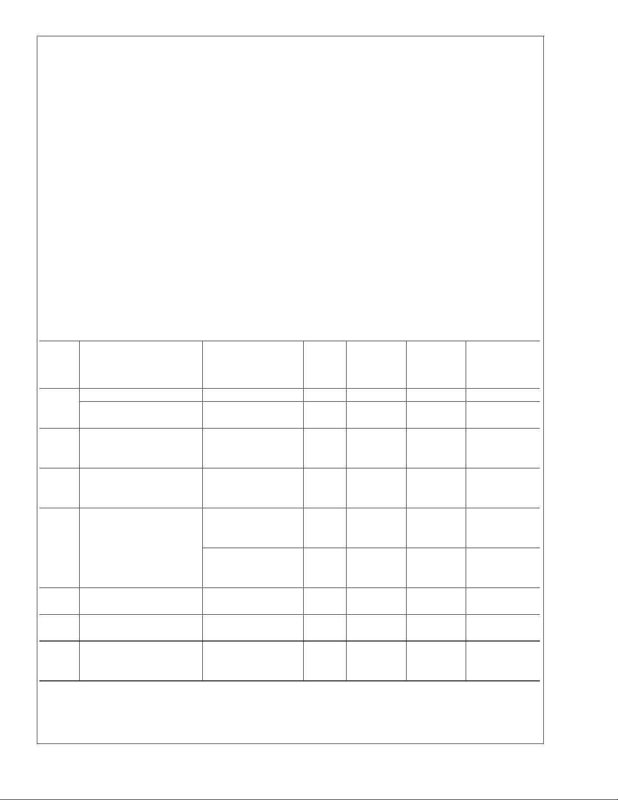
Ordering Information
Reverse
Breakdown
Voltage Tolerance
at 25˚C and
Average Reverse
Breakdown
Voltage
Temperature
Coefficient
±
0.1%, 100 ppm/˚C
max (A grade)
±
0.2%, 100 ppm/˚C
max (B grade)
±
0.5%, 100 ppm/˚C
max (C grade)
±
1.0%, 150 ppm/˚C
max (D grade)
±
2.0%, 150 ppm/˚C
max (E grade)
Supplied as 1000
Units Tape and
Reel
LM4041AIM3-1.2 LM4041AIM3X-1.2 LM4041AIZ-1.2 MF03A,
LM4041BIM3-1.2 LM4041BIM3X-1.2 LM4041BIM7-1.2 LM4041BIM7X-1.2 LM4041BIZ-1.2 MF03A,
LM4041CEM3-1.2
LM4041CIM3-1.2
LM4041CEM3-ADJ
LM4041CIM3-ADJ
LM4041DEM3-1.2
LM4041DIM3-1.2
LM4041DEM3-ADJ
LM4041DIM3-ADJ
LM4041EEM3-1.2
LM4041EIM3-1.2
DS011392-3
Bottom View
See NS Package Number Z03A
Package
M3 (SOT-23) M7 (SC70) Z (TO-92)
Supplied as 3000
Units Tape and
Reel
LM4041CEM3X-1.2
LM4041CIM3X-1.2
LM4041CEM3X-ADJ
LM4041CIM3X-ADJ
LM4041DEM3X-1.2
LM4041DIM3X-1.2
LM4041DEM3X-ADJ
LM4041DIM3X-ADJ
LM4041EEM3X-1.2
LM4041EIM3X-1.2
Supplied as
1000 Units Tape
and Reel
LM4041CIM7-1.2
LM4041CIM7-ADJ
LM4041DIM7-1.2
LM4041DIM7-ADJ
LM4041EIM7-1.2 LM4041EIM7X-1.2 LM4041EIZ-1.2 MF03A,
Supplied as 3000
Units Tape and
LM4041CIM7X-1.2
LM4041CIM7X-ADJ
LM4041DIM7X-1.2
LM4041DIM7X-ADJ
DS011392-32
Reel
LM4041CIZ-1.2
LM4041CIZ-ADJ
LM4041DIZ-1.2
LM4041DIZ-ADJ
NS
Package
Number
Z03A
Z03A,
MAA05A
MF03A,
Z03A,
MAA05A
MF03A,
Z03A,
MAA05A
Z03A,
MAA05A
SOT-23 and SC70 Package Marking Information
Only three fields of marking are possible on the SOT-23’s and SC70’s small surface. This table gives the meaning of the three
fields.
Part Marking Field Definition
R1A (SOT-23 Only) First Field:
R1B R = Reference
R1C Second Field:
R1D 1 = 1.225V Voltage Option
R1E A = Adjustable
Third Field:
RAC A–E = Initial Reverse Breakdown
RAD Voltage or Reference Voltage Tolerance
±
A=
0.1%, B =±0.2%, C =±0.5%, D =±1.0%, E =±2.0%
www.national.com 2
LM4041
Absolute Maximum Ratings (Note 1)
If Military/Aerospace specified devices are required,
please contact the National SemiconductorSalesOffice/
Distributors for availability and specifications.
Reverse Current 20 mA
Forward Current 10 mA
Soldering (10 seconds) +260˚C
ESD Susceptibility
Human Body Model (Note 3) 2 kV
Machine Model (Note 3) 200V
See AN-450 “Surface Mounting Methods and Their Effect
on Product Reliability” for other methods of soldering
surface mount devices.
Maximum Output Voltage
(LM4041-ADJ) 15V
Power Dissipation (T
= 25˚C) (Note 2)
A
M3 Package 306 mW
Z Package 550 mW
M7 Package 241mW
Storage Temperature −65˚C to +150˚C
Lead Temperature
M3 Packages
Vapor phase (60 seconds) +215˚C
Infrared (15 seconds) +220˚C
Operating Ratings(Notes 1, 2)
Temperature Range (T
Industrial Temperature Range −40˚C ≤ T
Extended Temperature Range −40˚C ≤ T
Reverse Current
LM4041-1.2 60 µA to 12 mA
LM4041-ADJ 60 µA to 12 mA
Output Voltage Range
LM4041-ADJ 1.24V to 10V
Z Package
LM4041-1.2
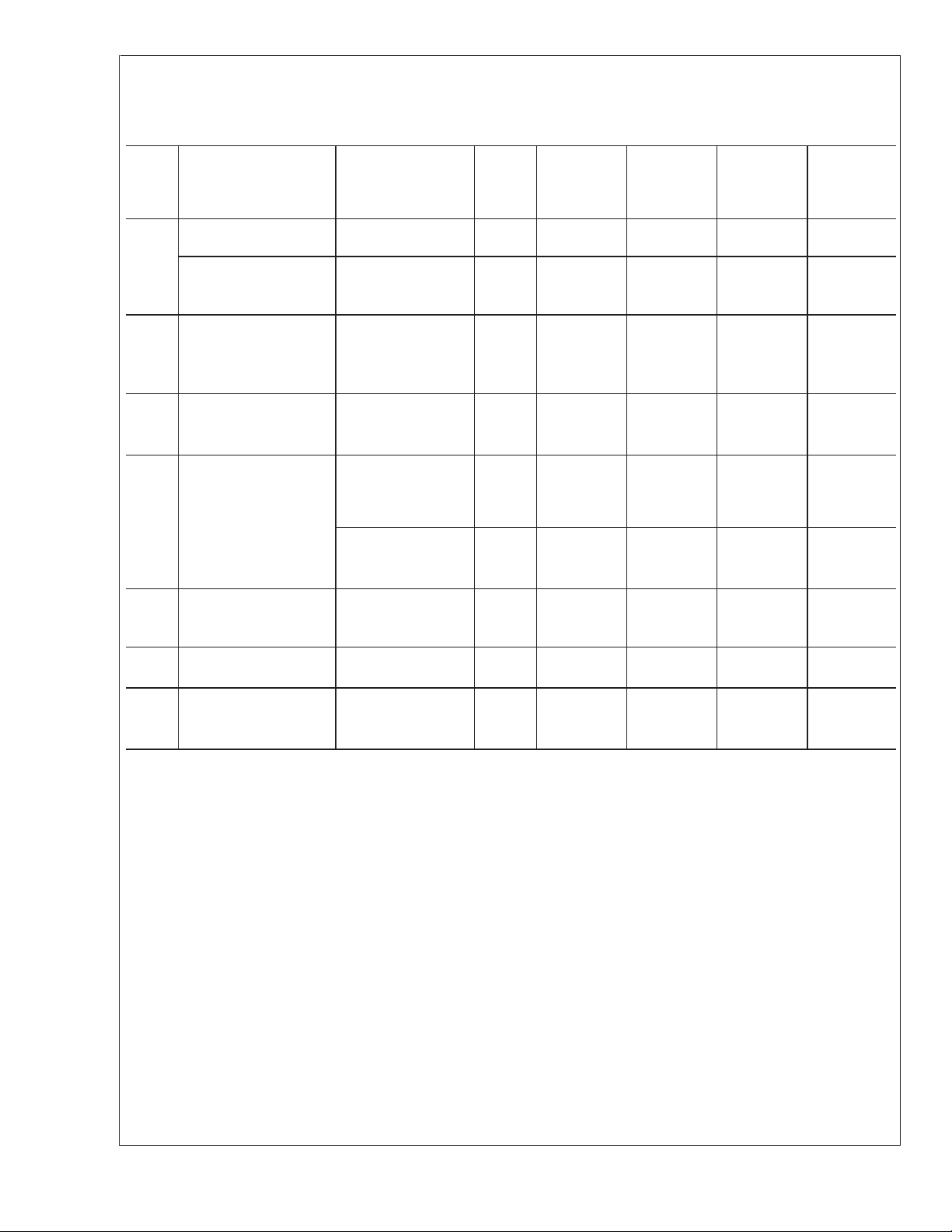
Electrical Characteristics (Industrial Temperature Range)
Boldface limits apply for TA=TJ=T
verse Breakdown Voltage tolerances of
Symbol Parameter Conditions Typical
V
R
Reverse Breakdown Voltage IR= 100 µA 1.225 V
Reverse Breakdown Voltage I
Tolerance (Note 6)
I
RMIN
∆V
Minimum Operating Current 45 µA
/∆T Average Reverse Breakdown
R
Voltage Temperature
Coefficient (Note 6)
∆V
/∆IRReverse Breakdown Voltage
R
Change with Operating
Current Change
Z
R
e
N
∆V
Reverse Dynamic Impedance IR= 1 mA, f = 120 Hz, 0.5 Ω
Wideband Noise IR= 100 µA 20 µV
Reverse Breakdown Voltage
R
Long Term Stability
to T
MIN
±
0.1% and±0.2%, respectively.
R
I
R
I
R
I
R
I
RMIN
1mA≤I
I
AC
; all other limits TA=TJ= 25˚C. The grades A and B designate initial Re-
MAX
= 100 µA
=10mA
=1mA
= 100 µA
≤ IR≤ 1 mA 0.7 mV
≤12 mA 4.0 mV
R
= 0.1 I
R
10 Hz ≤ f ≤ 10 kHz
t = 1000 hrs
= 100 µA
±
0.1˚C 120 ppm
T = 25˚C
I
R
(Note 4)
LM4041AIZ
Limits
(Note 5)
LM4041AIM3
±
1.2
±
9.2
60 60 µA (max)
65 65 µA (max)
±
20 ppm/˚C
±
15
±
15 ppm/˚C
±
100
1.5 1.5 mV (max)
2.0 2.0 mV (max)
6.0 6.0 mV (max)
8.0 8.0 mV (max)
1.5 1.5 Ω (max)
min
LM4041BIM3
LM4041BIZ
LM4041BIM7
Limits
(Note 5)
±
2.4 mV (max)
±
10.4 mV (max)
±
100 ppm/˚C (max)
≤ TA≤ T
≤ +85˚C
A
≤ +125˚C
A
Units
(Limit)
rms
max
)
www.national.com3
LM4041-1.2
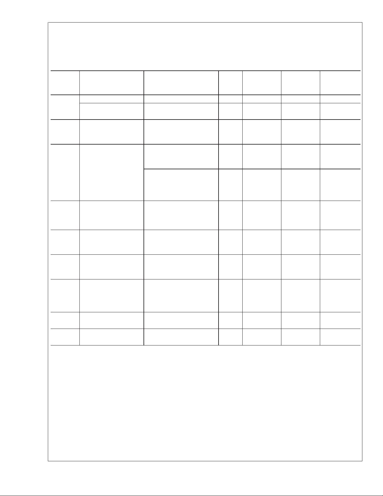
Electrical Characteristics (Industrial Temperature Range)
LM4041
Boldface limits apply for TA=TJ=T
verse Breakdown Voltage tolerances of
Symbol Parameter Conditions Typical
V
R
Reverse Breakdown
Voltage
Reverse Breakdown
Voltage
Tolerance (Note 6)
I
Minimum Operating
RMIN
Current
∆V
/∆TVRTemperature
R
Coefficient (Note 6)
∆V
/∆IRReverse Breakdown
R
Voltage Change with
Operating Current
Change
Z
Reverse Dynamic
R
Impedance
e
N
∆V
Wideband Noise IR= 100 µA 20 µV
Reverse Breakdown
R
Voltage Long Term
Stability
to T
MIN
±
0.5%,±1.0% and±2.0%, respectively.
; all other limits TA=TJ= 25˚C. The grades C, D and E designate initial Re-
MAX
LM4041CIM3
(Note 4)
LM4041CIZ
LM4041CIM7
Limits
(Note 5)
IR= 100 µA 1.225 V
I
= 100 µA
R
±
6
±
14
45 µA
60 65 65 µA (max)
65 70 70 µA (max)
IR=10mA
I
=1mA
R
I
= 100 µA
R
≤ IR≤ 1 mA 0.7 mV
I
RMIN
±
20 ppm/˚C
±
15
±
15 ppm/˚C
±
100
1.5 2.0 2.0 mV (max)
2.0 2.5 2.5 mV (max)
1mA≤I
≤12 mA 2.5 mV
R
6.0 8.0 8.0 mV (max)
8.0 10.0 10.0 mV (max)
IR= 1 mA,
0.5 Ω
f = 120 Hz
I
AC
= 0.1 I
R
1.5 2.0 2.0 Ω(max)
10 Hz ≤ f ≤ 10 kHz
t = 1000 hrs
±
T = 25˚C
I
= 100 µA
R
0.1˚C 120 ppm
LM4041DIM3
LM4041DIZ
LM4041DIM7
Limits(Note
5)
±
12
±
24
±
150
LM4041EIM3
LM4041EIZ
LM4041EIM7
Limits
(Note 5)
±
25 mV (max)
±
36 mV (max)
±
150 ppm/˚C (max)
Units
(Limit)
rms
www.national.com 4

LM4041-1.2
Electrical Characteristics (Extended Temperature Range)
LM4041
Boldface limits apply for TA=TJ=T
verse Breakdown Voltage tolerance of
to T
MIN
±
0.5%,±1.0% and±2.0% respectively.
; all other limits TA=TJ= 25˚C. The grades C, D and E designate initial Re-
MAX
Symbol Parameter Conditions Typical
(Note 4)
V
R
Reverse Breakdown
IR= 100 µA 1.225 V
Voltage
Reverse Breakdown
I
= 100 µA
R
Voltage Error
(Note 6)
I
RMIN
Minimum Operating
45 µA
Current
∆V
/∆T VR Temperature
R
Coefficient(Note 6)
∆V
/∆IRReverse Breakdown
R
IR=10mA
I
=1mA
R
I
= 100 µA
R
≤ IR≤ 1.0 mA 0.7 mV
I
RMIN
±
20 ppm/˚C
±
15
±
15 ppm/˚C
Change with
Current
1mA≤I
Z
R
e
N
Reverse Dynamic
Impedance
IR=1mA,f=120
Hz,
I
AC
Noise Voltage IR= 100 µA 20 µV
≤12 mA 2.5 mV
R
0.5 Ω
= 0.1 I
R
10 Hz ≤ f ≤ 10 kHz
∆V
Long Term Stability
R
(Non-Cumulative)
t = 1000 hrs
T = 25˚C
I
R
±
= 100 µA
0.1˚C 120 ppm
LM4041CEM3
Limits
(Note 5)
±
±
18.4
6
LM4041DEM3
Limits
(Note 5)
±
12
±
31
LM4041EEM3
Limits
(Note 5)
±
25 mV (max)
±
43 mV (max)
60 65 65 µA (max)
68 73 73 µA (max)
±
100
±
150
±
150 ppm/˚C
1.5 2.0 2.0 mV (max)
2.0 2.5 2.5 mV (max)
6.0 8.0 8.0 mV (max)
8.0 10.0 10.0 mV (max)
1.5 2.0 2.0 Ω (max)
Units
(Limit)
(max)
rms
www.national.com5
LM4041-ADJ (Adjustable)
LM4041
Electrical Characteristics (Industrial Temperature Range)
Boldface limits apply for TA=TJ=T
7)), I
and
≤ IR≤ 12 mA, V
RMIN
±
1%, respectively for V
REF
OUT
≤ V
OUT
= 5V.
Symbol Parameter Conditions Typical
V
REF
Reference Voltage IR= 100 µA, V
Reference Voltage I
Tolerance (Note 8)
I
RMIN
Minimum Operating
Current
∆V
/∆IRReference Voltage
REF
Change with Operating
Current Change
∆V
/∆VOReference Voltage
REF
Change
with Output Voltage
Change
I
FB
∆V
REF
Feedback Current 60 nA
/∆T Average Reference
Voltage Temperature
Coefficient (Note 8)
Z
OUT
Dynamic Output
Impedance
e
∆V
N
REF
Wideband Noise IR= 100 µA V
Reference Voltage Long t = 1000 hrs, IR= 100 µA 120 ppm
Term Stability T = 25˚C
MIN
to T
; all other limits TJ= 25˚C unless otherwise specified (SOT-23, see (Note
MAX
≤ 10V. The grades C and D designate initial Reference Voltage Tolerances of±0.5%
= 5V 1.233 V
OUT
= 100 µA, V
R
≤ IR≤ 1 mA 0.7 mV
I
RMIN
SOT-23: V
OUT
=5V
OUT
≥ 1.6V 1.5 2.0 mV (max)
(Note 7) 2.0 2.5 mV (max)
1mA≤I
SOT-23: V
≤12 mA 2 mV
R
≥ 1.6V (Note
OUT
7)
= 1 mA −1.55 mV/V
I
R
= 5V, IR= 10 mA 20 ppm/˚C
V
OUT
I
= 1 mA 15
R
I
= 100 µA 15 ppm/˚C
R
IR= 1 mA, f = 120 Hz,
I
= 0.1 I
AC
R
V
OUT=VREF
V
= 10V 2 Ω
OUT
OUT=VREF
10 Hz ≤ f ≤ 10 kHz
±
0.1˚C
(Note
4)
LM4041CIM3
LM4041CIZ
LM4041CIM7
(Note 5)
±
6.2
±
14
LM4041DIM3
LM4041DIZ
LM4041DIM7
(Note 5)
±
12 mV (max)
±
24 mV (max)
(Limit)
45 µA
60 65 µA (max)
65 70 µA (max)
4 6 mV (max)
68mV (max)
−2.0 −2.5 mV/V (max)
−2.5 −3.0 mV/V (max)
100 150 nA (max)
120 200 nA (max)
±
100
±
150 ppm/˚C (max)
0.3 Ω
20 µV
Units
rms
www.national.com 6
 Loading...