

LM380
2.5W Audio Power Amplifier
General Description
The LM380 is a power audio amplifier for consumer applications. In order to hold system cost to a minimum, gain is
internally fixed at 34 dB. A unique input stage allows ground
referenced input signals. The output automatically selfcenters to one-half the supply voltage.
The output is short circuit proof with internal thermal limiting.
The package outline is standard dual-in-line. The LM380N
uses a copper lead frame. The center three pins on either
side comprise a heat sink. This makes the device easy to
use in standard PC layouts.
Uses include simple phonograph amplifiers, intercoms, line
drivers, teaching machine outputs, alarms, ultrasonic drivers, TV sound systems, AM-FM radio, small servo drivers,
power converters, etc.
August 2000
A selected part for more power on higher supply voltages is
available as the LM384. For more information see AN-69.
Features
n Wide supply voltage range: 10V-22V
n Low quiescent power drain: 0.13W (V
n Voltage gain fixed at 50
n High peak current capability: 1.3A
n Input referenced to GND
n High input impedance: 150kΩ
n Low distortion
n Quiescent output voltage is at one-half of the supply
voltage
n Standard dual-in-line package
= 18V)
S
LM380 2.5W Audio Power Amplifier
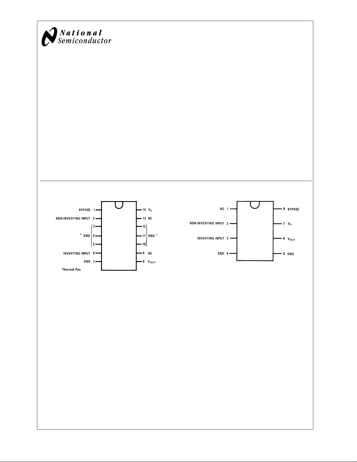
Connection Diagrams (Dual-In-Line Packages, Top View)
00697701
Order Number LM380N
See NS Package Number N14A
Order Number LM380N-8
00697702
See NS Package Number N08E
© 2004 National Semiconductor Corporation DS006977 www.national.com
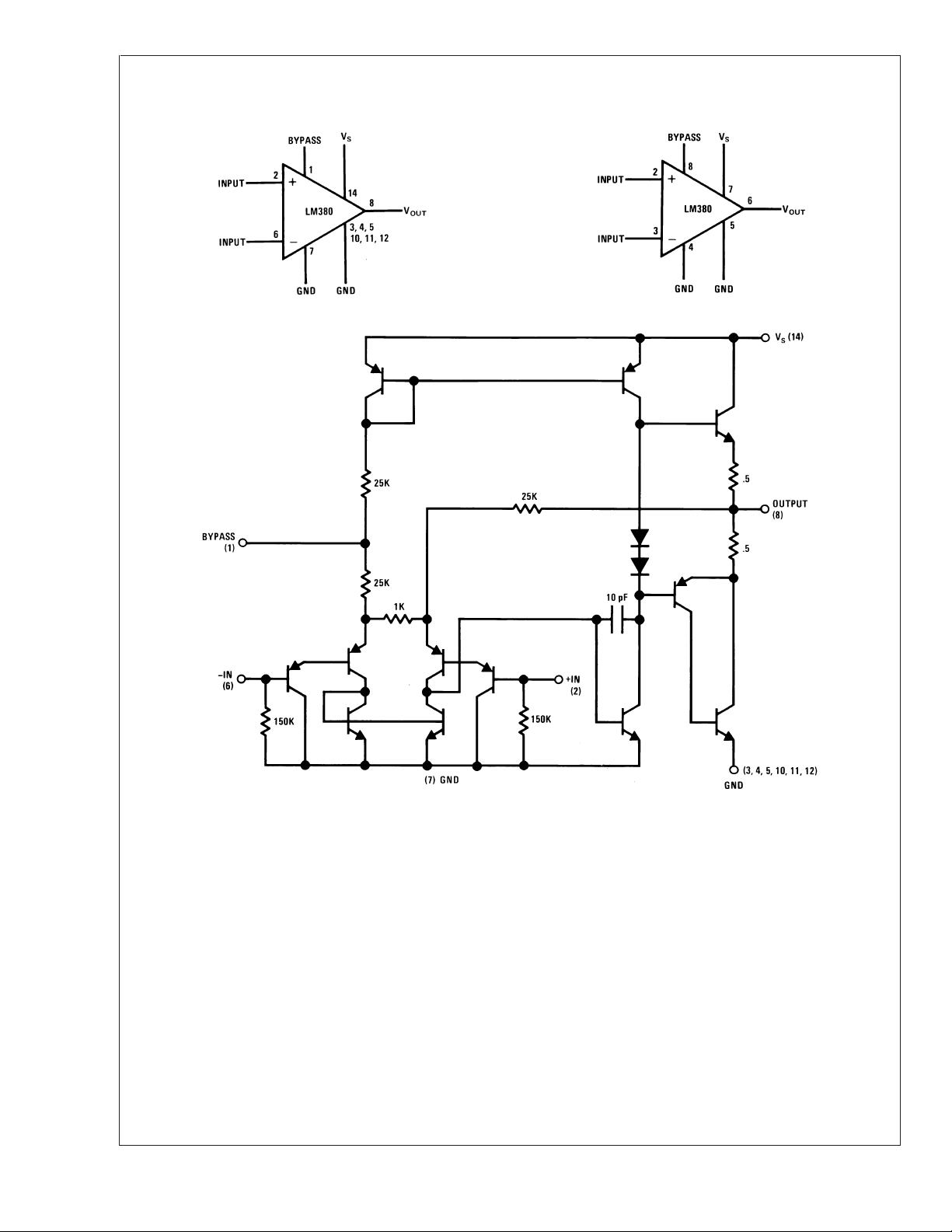
Block and Schematic Diagrams
LM380
LM380N LM380N-8
00697703
00697704
www.national.com 2
00697705
LM380
Absolute Maximum Ratings (Note 1)
If Military/Aerospace specified devices are required,
please contact the National Semiconductor Sales Office/
Distributors for availability and specifications.
Supply Voltage 22V
Peak Current 1.3A
Package Dissipation 14-Pin DIP (Note
7) 8.3W
Package Dissipation 8-Pin DIP (Note 7) 1.67W
±
Input Voltage
0.5V
Operating Temperature 0˚C to +70˚C
Junction Temperature +150˚C
Lead Temperature (Soldering, 10 sec.) +260˚C
ESD rating to be determined
Thermal Resistance
θ
(14-Pin DIP) 30˚C/W
JC
θ
(8-Pin DIP) 37˚C/W
JC
θ
(14-Pin DIP) 79˚C/W
JA
θ
(8-Pin DIP) 107˚C/W
JA
Storage Temperature −65˚C to
+150˚C
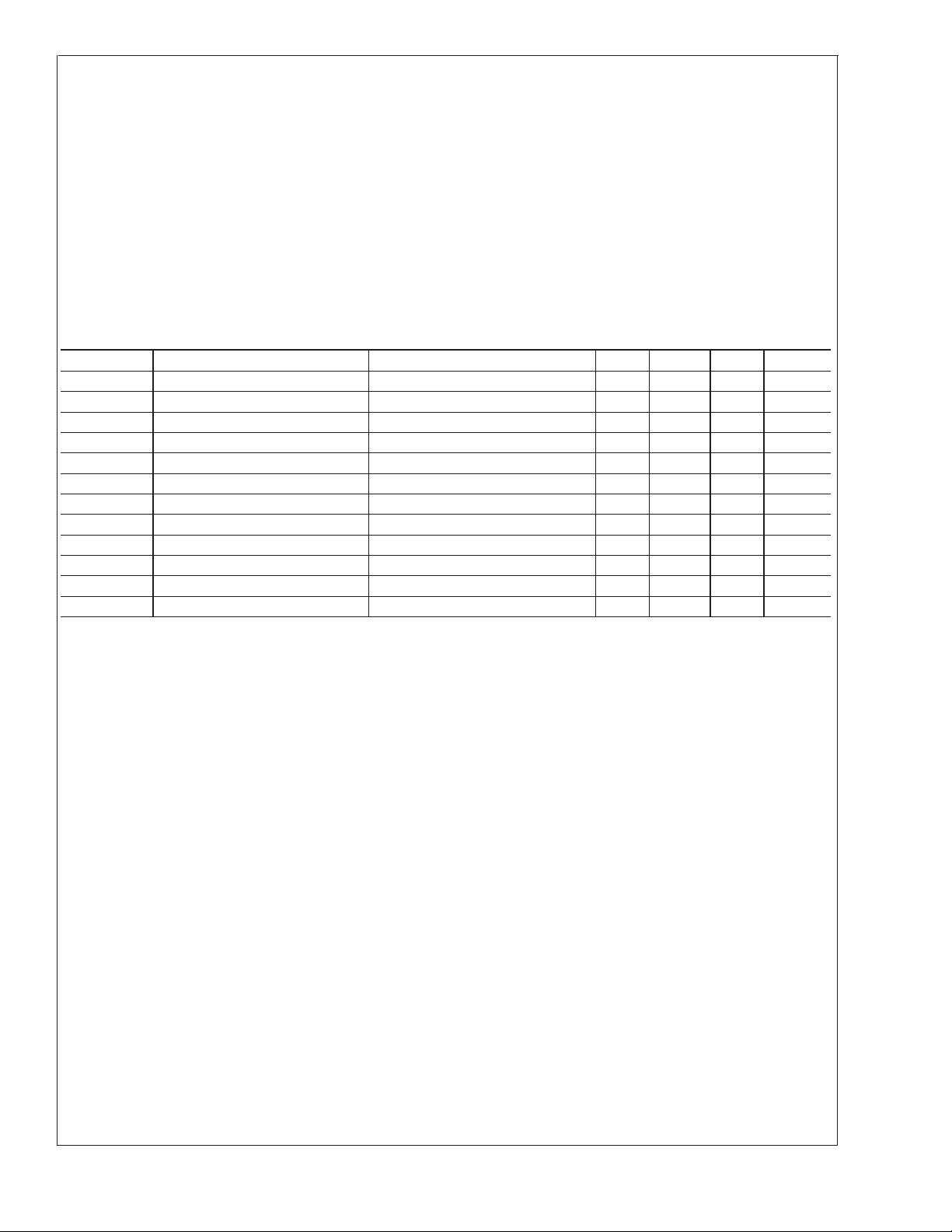
Electrical Characteristics (Note 2)
Symbol Parameter Conditions Min Typ Max Units
P
OUT(RMS)
A
V
V
OUT
Z
IN
THD Total Harmonic Distortion (Notes 5, 6) 0.2 %
PSRR Power Supply Rejection Ratio (Note 3) 38 dB
V
S
BW Bandwidth P
I
Q
V
OUTQ
I
BIAS
I
SC
Note 1: “Absolute Maximum Ratings” indicate limits beyond which damage to the device may occur. Operating Ratings indicate conditions for which the device is
functional, but do not guarantee specific performance limits.
Note 2: V
Note 3: Rejection ratio referred to the output with C
Note 4: With device Pins 3, 4, 5, 10, 11, 12 soldered into a 1/16" epoxy glass board with 2 ounce copper foil with a minimum surface of 6 square inches.
Note 5: C
Note 6: The maximum junction temperature of the LM380 is 150˚C.
Note 7: The package is to be derated at 15˚C/W junction to heat sink pins for 14-pin pkg; 75˚C/W for 8-pin.
Output Power RL=8Ω, THD = 3% (Notes 4, 5) 2.5 W
Gain 40 50 60 V/V
Output Voltage Swing RL=8Ω 14 V
Input Resistance 150k Ω
Supply Voltage 10 22 V
= 2W, RL=8Ω 100k Hz
OUT
Quiescent Supply Current 7 25 mA
Quiescent Output Voltage 8 9.0 10 V
Bias Current Inputs Floating 100 nA
Short Circuit Current 1.3 A
= 18V and TA= 25˚C unless otherwise specified.
S
= 0.47 µfd on Pin 1.
BYPASS
BYPASS
=5µF.
p-p
www.national.com3
 Loading...