

National Semiconductor LM3702, LM3703 Technical data
September 2003
LM3702/LM3703
Microprocessor Supervisory Circuits with Low Line
Output and Manual Reset
General Description
The LM3702/LM3703 series of microprocessor supervisory
circuits provide the maximum flexibility for monitoring power
supplies and battery controlled functions in systems without
backup batteries. The LM3702/LM3703 series are available
in a 9-bump micro SMD package.
Built-in features include the following:
Reset: Reset is asserted during power-up, power-down, and
brownout conditions. RESET is guaranteed down to V
1.0V.
Manual Reset Input: An input that asserts reset when pulled
low.
Low Line Output: This early power failure warning indicator
goes low when the supply voltage drops to a value which is
2% higher than the reset threshold voltage.
CC
Features
n Standard Reset Threshold voltage: 3.08V
n Custom Reset Threshold voltages: For other voltages
between 2.2V and 5.0V in 10mV increments, contact
National Semiconductor Corp.
n No external components required
n Manual-Reset input
n RESET (LM3702) or RESET (LM3703) outputs
n Precision supply voltage monitor
n Factory programmable Reset Timeout Delay
n Available in micro SMD package for minimum footprint
±
n
0.5% Reset threshold accuracy at room temperature
±
n
2% Reset threshold accuracy over temperature
of
extremes
n Reset assertion down to 1V V
n 28 µA VCCsupply current
(RESET option only)
CC
Applications
n Embedded Controllers and Processors
n Intelligent Instruments
n Automotive Systems
n Critical µP Power Monitoring
LM3702/LM3703 Microprocessor Supervisory Circuits with Low Line Output and Manual Reset
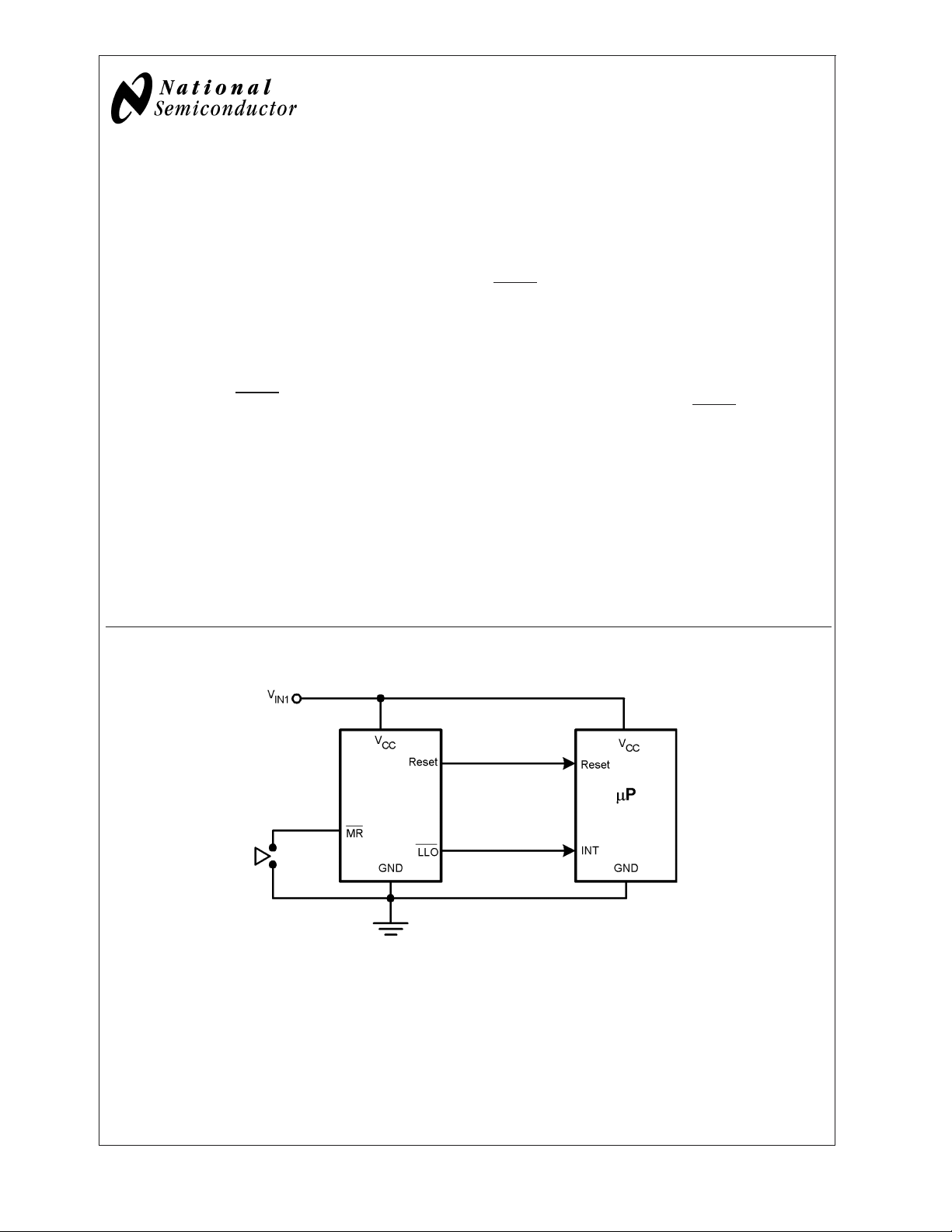
Typical Application
20011503
© 2003 National Semiconductor Corporation DS200115 www.national.com

Connection Diagram
Top View
(looking from the coating side)
micro SMD 9 Bump Package
BPA09
LM3702/LM3703
20011501
Pin Descriptions
Bump No. Name Function
A1 MR
B1 V
CC
C1 RESET
RESET Reset Logic Output. RESET is the inverse of RESET (LM3703 only).
C3 LLO Low-Line Logic Output. Early Power-Fail warning output. Low when VCCfalls below V
B3 GND Ground reference for all signals.
A2, A3, C2 NC No Connect.
B2 NC No Connect. Test input used at factory only. Leave floating.
Manual-Reset input. When MR is less than V
RESET/RESET is engaged.
Power Supply input.
Reset Logic Output. Pulses low for tRP(Reset Timeout Period) when triggered, and stays
low whenever V
is below the reset threshold or when MR is below V
CC
for tRPafter either VCCrises above the reset threshold, or after MR input rises above
V
(LM3702 only).
MRT
(Low-Line Output Threshold). This output can be used to generate an NMI (Non-Maskable
Interrupt) to provide an early warning of imminent power-failure.
(Manual Reset Threshold)
MRT
. It remains low
MRT
LLOT
www.national.com 2
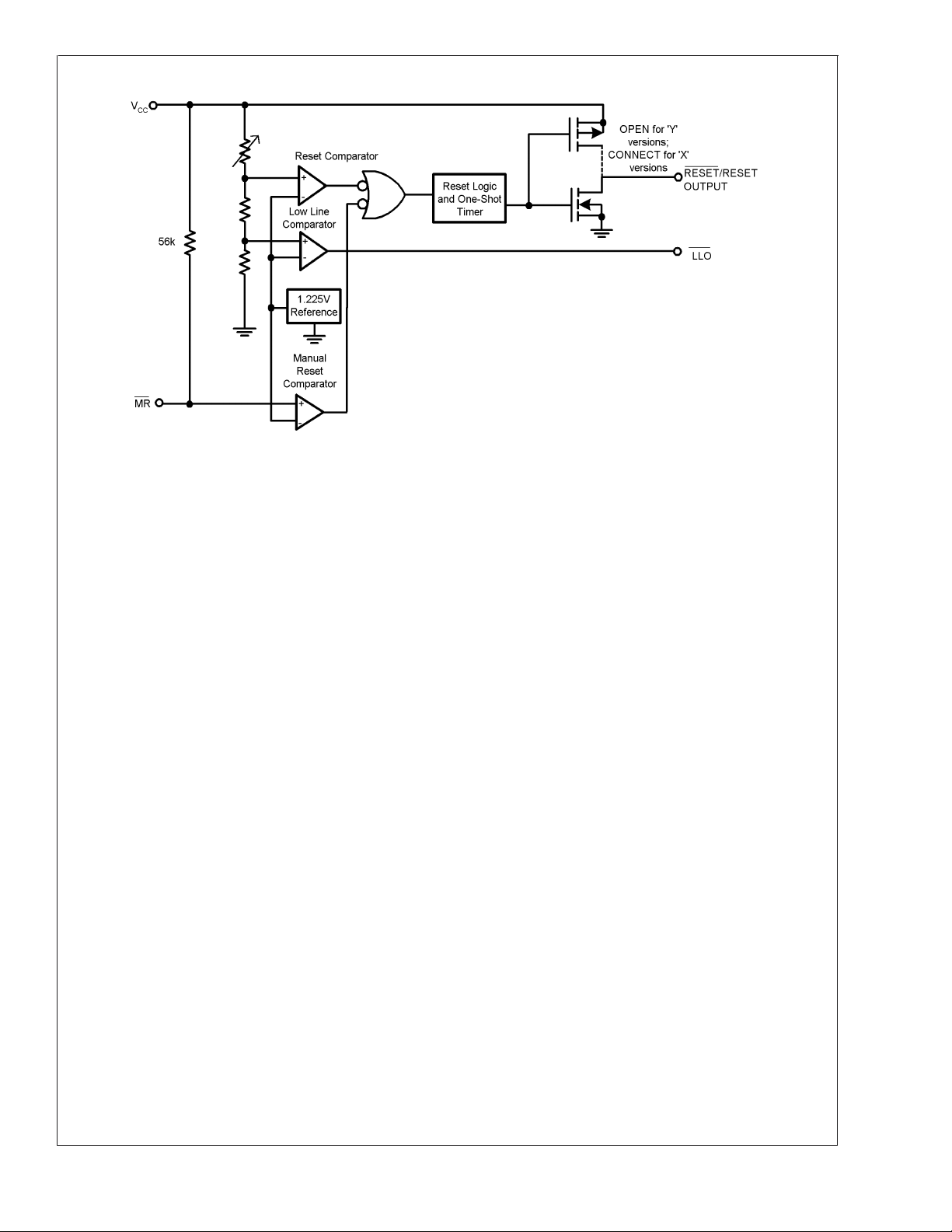
Block Diagram
LM3702/LM3703
20011505
www.national.com3
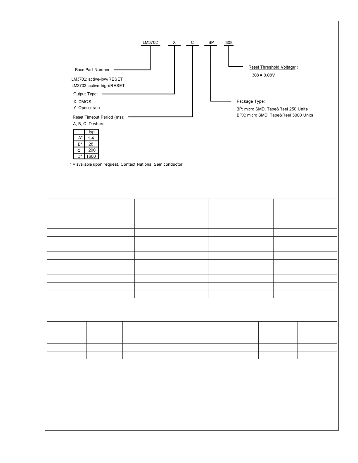
Ordering Information
LM3702/LM3703
*For other voltages between 2.2V and 5.0V, please contact National Semiconductor sales office.
20011504
LM3702/LM3703
Reset
Part Number Output
LM3702XCBP-308 totem-pole 200ms %%I2
LM3702XCBPX-308 totem-pole 200ms %%I2
LM3703XCBP-308 totem-pole 200ms %%I3
LM3703XCBPX-308 totem-pole 200ms %%I3
LM3703XDBP-308 totem-pole 1600ms %%124
LM3703XDBPX-308 totem-pole 1600ms %%124
LM3702YABP-308 open-drain 1.4ms %%131
LM3702ABPX-308 open-drain 1.4ms %%131
LM3702YDBP-220 open-drain 1600ms %%125
LM3702YDBPX-220 open-drain 1600ms %%125
%% is the datecode and will vary with time.
Timeout
Period
Package
Marking
Table Of Functions
Part
Number
LM3702 x X, Y* Customized x x
LM3703 x X Customized x x
* = available upon request. Contact National
Active
Low
Reset
Active
High
Reset
Output
(X = totem-pole)
(Y = open-drain)
Reset
Timeout
Period
Manual
Reset
Low
Line
Output
www.national.com 4
 Loading...