

National Semiconductor LM32, LM40, LM41 User Manual

National Semiconductor is now part of
Texas Instruments.
Search http://www.ti.com/ for the latest technical
information and details on our current products and services.
1 of 22

© Copyright 2004 National Semiconductor Corporation 1 www.national.com
Revision B
November 9, 2004
LM32, LM40, LM41 Evaluation Board User’s Guide
LM32
,
LM40
,
LM41 Evaluation Board User’s Guide
2 of 22

© Copyright 2004 National Semiconductor Corporation 2 www.national.com
LM32, LM40, LM41 Evaluation Board User’s Guide
Table of Contents
Table of Contents 2
References 3
1.0 Introduction 4
1.1 Block Diagram 4
2.0 Quick Start 5
2.1 Quick Start Diagram 5
2.2 LM32 Quick Start 6
2.3 LM40 Quick Start 8
2.4 LM41 Quick Start 10
3.0 Functional Description 12
3.1 Evaluation Board Connection Tables 12
3.1.1 LM32 Evaluation Board Connection Table 12
3.1.2 LM40 Evaluation Board Connections Table 13
3.1.3 LM41 Evaluation Board Connections Table 14
4.0 Software Installation and Operation 15
5.0 Electrical and Mechanical Specifications 16
5.1 Electrical Specifications 16
5.2 Electrical Schematic 16,17
5.3 Evaluation Board Layout 18
5.4 Bill of Materials 19
5.5 Mechanical Specifications 20
5.5.1 Operating Mechanical and Environmental Specifications 20
5.5.2 Evaluation Board Mechanical Dimensions 20
5.5.3 Electrostatic Discharge (ESD) Precautions 20
3 of 22

© Copyright 2004 National Semiconductor Corporation 3 www.national.com
LM32, LM40, LM41 Evaluation Board User’s Guide
References
1. Datasheet for the device on the evaluation board:
a. “LM32 Dual Thermal Diode Temperature Sensor With SensorPath™ Bus” or
b. “LM40 Hardware Monitor with Dual Thermal Diodes and SensorPath™ Bus” or
c. “LM41 Hardware Monitor with Thermal Diode Inputs and SensorPath™ Bus”
The latest copy of the LM32, LM40, LM41 datasheets can be obtained by going to the National
Semiconductor website www.national.com, by searching on “LM32”, “LM40”, or “LM41”, and then
downloading the appropriate datasheet file.
2. SensorEval, Version 1.04b or later, Evaluation Board CD containing:
a. The SensorEval.exe executable program used to run the LM32, LM40, or LM41
Evaluation Boards.
b. A softcopy of this User’s Guide
c. A readme.txt file with useful information about the program.
d. A softcopy of the SensorEval Software manual.
4 of 22
© Copyright 2004 National Semiconductor Corporation 4 www.national.com
1.0 Introduction
The LM32/LM40/LM41 Evaluation Board is
used together with the National Semiconductor
SensorEval software (provided in the kit), and
with a USB cable (not provided in the kit), and
with an external personal computer (PC).
Power to the LM32/LM40/LM41 Evaluation
Board is provide by the +5VDC line of the USB
connection. No external power supply or signal
sources are required for operation of the
LM32/LM40/LM41 evaluation board.
Before connecting the PC to the
LM32/LM40/LM41 evaluation board through the
USB cable, the PC is first turned on and allowed
to go through its boot-up procedure. The user
installs and initiates the SensorEval software.
See Section 4.0 for software installation details.
After the SensorEval software is running, the
user can connect the USB cable first to the
computer and then to the LM32/LM40/LM41
Evaluation Board.
The PC should be able to recognize the board
and the user simply runs the SensorEval
software and selects the LM32/LM40/LM41 Eval
Board radio button. The software allows the
user to select which of the LM32, LM40, or
LM41 devices is used.
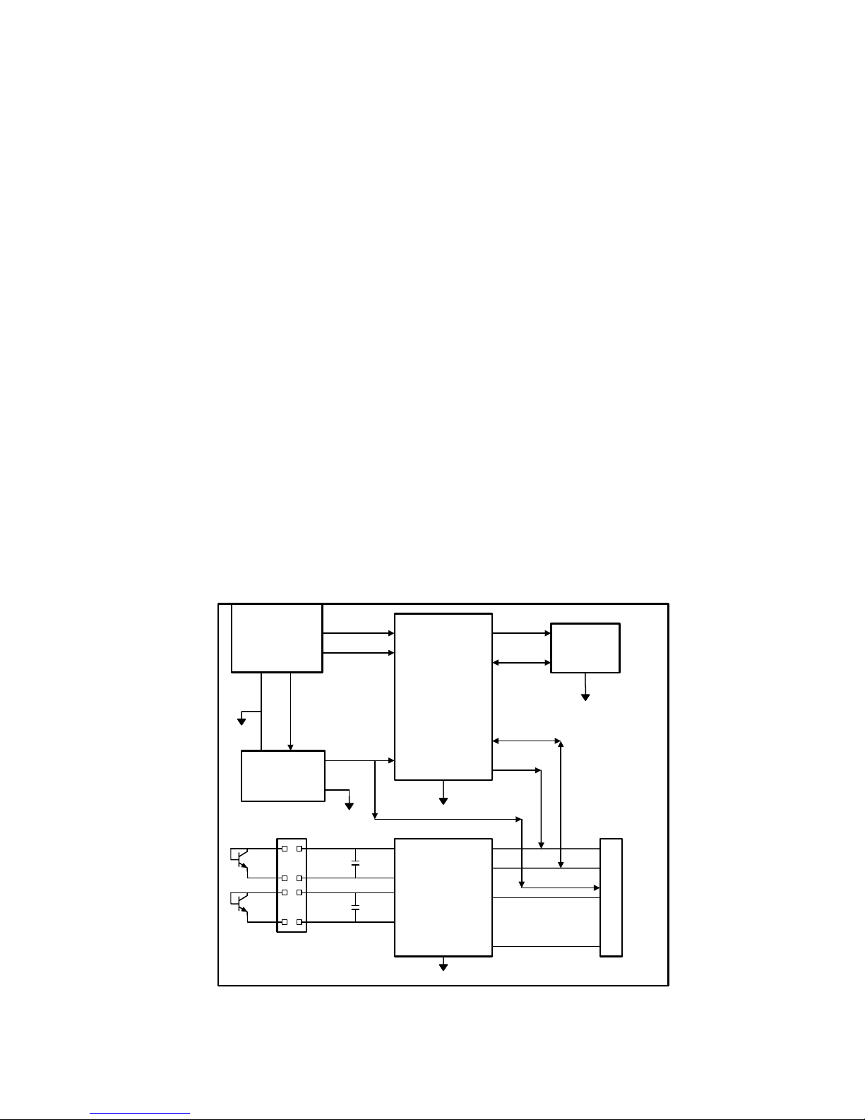
The block diagram below describes the
LM32/LM40/LM41 Evaluation Board itself. The
USB input provides the +5.0 VDC power to the
board, which is regulated down to 3.3 VDC to
power the IC’s. The EEPROM is programmed
at the factory with a unique ID code for this
particular board. When the USB cable is
plugged in, the PC interrogates the USB
devices and can identify this device as the
LM32/LM40/LM41 Evaluation Board.
The microcontroller on the board provides the
single wire signal (SWD), provides the address
(ADD) select signal, and relays the information
from the LM32, LM40, or LM41 to the PC via
the USB lines.
The pins available to the user for probing vary
according to device type. The output pinouts for
each of the LM32, LM40, or LM41 are shown in
the Connections sections and the Electrical
Schematic.
1.1 Block Diagram
USB
Input
EEPROM
Circuit
Voltage
Regulator
Circuit
Microcontroller
Circuitry
USB D+
USB D-
SCL
SDA
U5
LM32, LM40,
or LM41
+5.0 VDC
GND
+3.3 VDC
+3.3V
SWD
ADD
GND
SWD
ADD
D1+
D1D2+
D2-
Other Signals
depending on device.
(See Connections and
Schematic)
5 of 22
© Copyright 2004 National Semiconductor Corporation 5 www.national.com
2.0 Quick Start
1. Install the CD into the CD drive of the computer and install the SensorEval software (see Section
4.0).
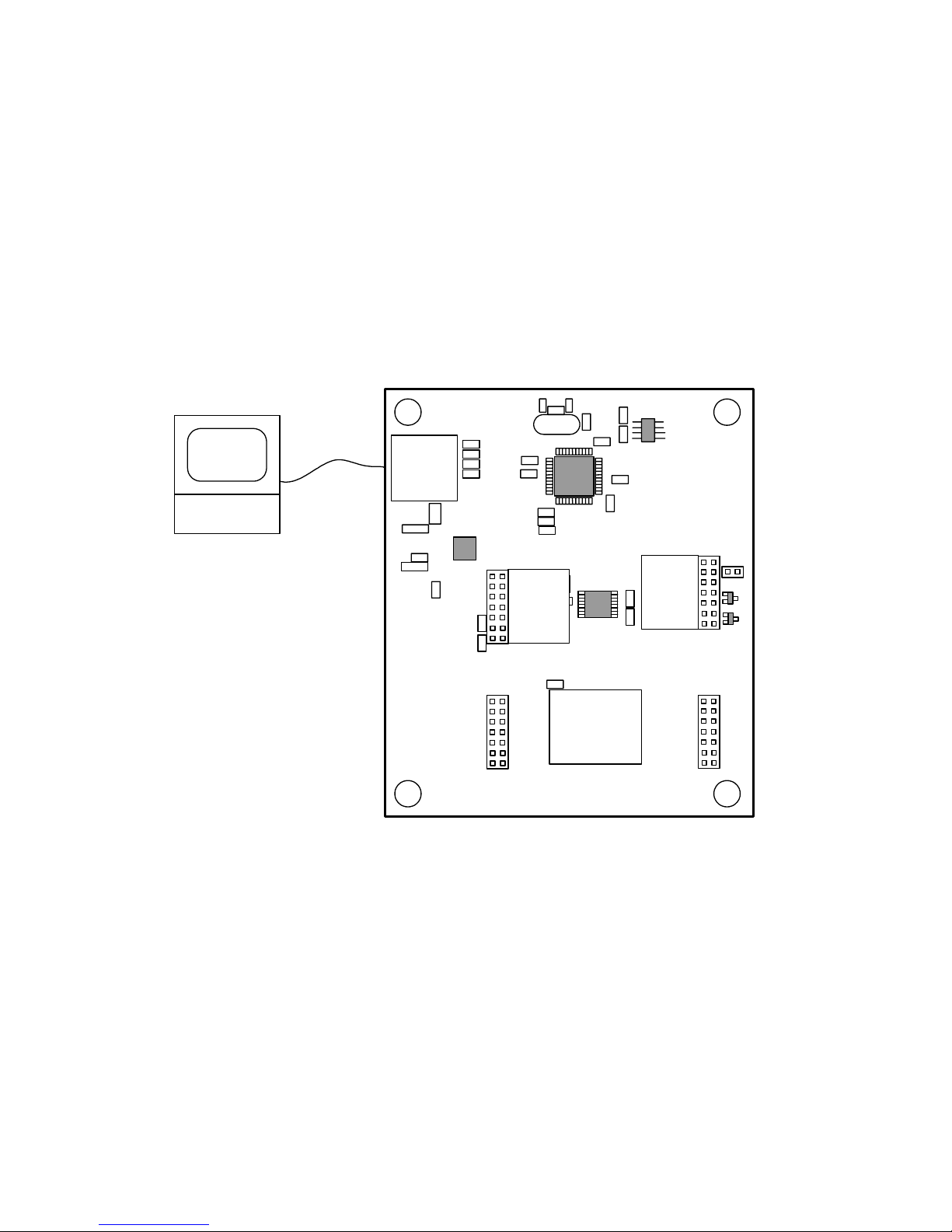
2. Hookup the USB cable between the PC or notebook computer and the LM32/LM40/LM41 Evaluation
Board as shown in Quick Start Diagram below.
2.1 Quick Start Diagram
Important! NO EXTERNAL POWER SUPPLY OR SIGNAL INPUTS ARE REQUIRED!
For
Socket
(not used)
LM32/40/41 Evaluation Board
National Semiconductor
Q1
LM41
LM40
LM32
LM32
LM40
LM41
U4
J3
J2
J6
Q2
See
Connection
Diagrams
See
Connection
Diagrams
LM32/40/41
PC with
SensorEval
software
installed
USB Cable
6 of 22
© Copyright 2004 National Semiconductor Corporation 6 www.national.com
2.2 LM32 Quick Start
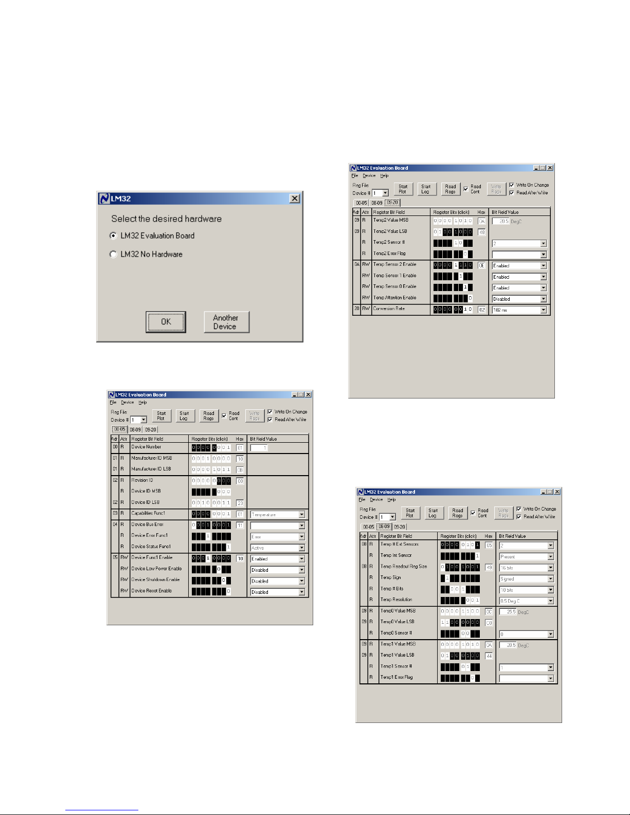
1. Run the SensorEval software by clicking the
icon on the desktop.
2. The first screen will look like this:
Select the LM32 Evaluation Board.
Click OK.
3. The next screen will look like this:
Select “Read Cont” box to read the temperature
continuously. Notice that there are three tabs for
the registers “00 through 05”, “08 through 09”,
and “09 through 20”. The first screen (above)
displays the registers 00hex through 05hex.
For Register 05, “Device Func1 Enable”,
select ENABLED.
4. Click on the 09-20 Register Tab.
The Screen should look like this:
For Register 0A select Enable for Temp Sensor
0, 1 and 2.Note that Temp2 (Remote sensor
[Q1 on the board] 2 is displayed in the box on
the right and is updated as the temperature of
the Q1 changes.
5. Click on the 08-09 Register Tab.
The screen should look like this:
7 of 22
 Loading...