

Page 1

VXI/VME
Getting Started with Your VXI/VMEpc™ 600 Series for Windows 95/NT
VXI/VMEpc 600 Series for Windows 95/NT
May 1998 Edition
Part Number 321882A-01
Page 2

Internet Support
E-mail: support@natinst.com
FTP Site: ftp.natinst.com
Web Address: http://www.natinst.com
Bulletin Board Support
BBS United States: 512 794 5422
BBS United Kingdom: 01635 551422
BBS France: 01 48 65 15 59
Fax-on-Demand Support
512 418 1111
Telephone Support (USA)
Tel: 512 795 8248
Fax: 512 794 5678
International Offices
Australia 03 9879 5166, Austria 0662 45 79 90 0, Belgium 02 757 00 20, Brazil 011 288 3336,
Canada (Ontario) 905 785 0085, Canada (Québec) 514 694 8521, Denmark 45 76 26 00, Finland 09 725 725 11,
France 01 48 14 24 24, Germany 089 741 31 30, Hong Kong 2645 3186, Israel 03 6120092, Italy 02 41 3091,
Japan 03 5472 2970, Korea 02 596 7456, Mexico 5 520 2635, Netherlands 0348 433466, Norway 32 84 84 00,
Singapore 2265886, Spain 91 640 0085, Sweden 08 730 49 70, Switzerland 056 200 51 51, Taiwan 02 377 1200,
United Kingdom 01635 523545
National Instruments Corporate Headquarters
6504 Bridge Point Parkway Austin, Texas 78730-5039 USA Tel: 512 794 0100
© Copyright 1998 National Instruments Corporation. All rights reserved.
Page 3

Important Information
Warranty
The National Instrumen ts VXI/V MEpc 600 Se ries em bedde d compute rs and access ories are warrante d ag ainst defect s in
materials and workmanship for a period of one year from the date of shipment, as evidenced by receipts or other
documentation. National Instrume nts w ill, at i ts option , re pair o r repla ce eq uipment that prove s to be defe ctive d urin g the
warranty period. This warranty includes parts and labor.
The media on which you receive National Instruments software are warranted not to fail to execute programming
instructions, due to defects in materials and workmanship, for a period of 90 days from date of shipment, as evidenced
by receipts or other documentation. National Instruments will, at its option, repair or replace software media that do not
execute programming instructions if National Instruments receives notice of such defects during the warranty period.
National Instruments does not warrant that the operation of the software shall be uninterrupted or error free.
A Return Material Authorization (RMA) number must be obtained from the factory and clearly marked on the outside
of the package before any equipment will be accepted for warranty wo rk. National Instru ments will pay the shippi ng costs
of returning to the owner part s which are c overed by warranty.
National Instruments believes that the informatio n in this manual is accurate. The document ha s been careful ly reviewed
for technical accurac y. In the even t that te chn ical or t ypograp hic al errors ex ist, Nation al Inst rumen ts res erves the righ t to
make changes to subsequent editions of this document without prior notice to holders of this edition. The reader should
consult National Instruments if errors are suspected. In no event shall National Instruments be liable for any damages
arising out of or related to this document or the information contained in it.
XCEPT AS SPECIFIED HEREIN
E
ANY WARRANTY OF MERCHANTABILITY OR FITNESS FOR A PARTICULAR PURPOSE
BY FAULT OR NEGLIGENCE ON THE PART OF NATIONAL INSTRUMENTS SHALL BE LIMITED TO THE AMOUNT THERETOFORE PAID BY THE
CUSTOMER
OR INCIDENTAL OR CONSEQUENTIAL DAMAGES, EVEN IF ADVISED OF THE POSSIBILITY THEREOF
National Instruments will apply regardless of the form of action, whether in contract or tort, including negligence.
Any action against National Instruments must be brought within one year after the cause of action accrues. National
Instruments shall not be liable for any delay in performance due to causes beyond its reasonable control. The warranty
provided herein does not cover damages, defects, malfunctions, or service failures caused by owner’s failure to follow
the National Instruments installation, operation, or maintenance instructions; owner’s modification of the product;
owner’s abuse, misuse, or negligent acts; and power failure or surges, fire, flood, accident, actions of third parties,
or other events outside reasonable control.
ATIONAL INSTRUMENTS WILL NOT BE LIABLE FOR DAMAGES RESULTING FROM LOSS OF DATA, PROFITS, USE OF PRODUCTS
. N
ATIONAL INSTRUMENTS MAKES NO WARRANTIES, EXPRESS OR IMPLIED, AND SPECIFICALLY DISCLAIMS
, N
USTOMER’S RIGHT TO RECOVER DAMAGES CAUSED
. C
. This limitation of the liability of
,
Copyright
Under the copyright laws, this publication may not be reproduced or transmitted in any form, electronic or mechanical,
including photocopyi ng, recordi ng, sto ring in an inform ati on retriev al syste m, or translat ing , in whole or in part, with out
the prior written consent of National Instruments Corporation.
Trademarks
CVI™, LabVIEW™, NI-488.2™, NI-VISA™, NI-VXI™, and VXI/VMEpc™ are trademarks of National Instruments
Corporation.
Product and company names listed are trademarks or trade names of their respective companies.
WARNING REGARDING MEDICAL AND CLINICAL USE OF NATIONAL INSTRUMENTS PRODUCTS
National Instruments products are not designed with components and testing intended to ensure a level of reliability
suitable for use in treatment and diagnosis of humans. Applications of National Instruments products involving medical
or clinical treatment can create a potential for accidental injury caused by product failure, or by errors on the part of the
user or application des igner. An y use or ap plica tion of Na tiona l Instrume nts p roducts for or inv olvi ng medic al or c linica l
treatment must be performed by properly trained and qualifie d medic al pe rsonnel, an d all traditio nal med ical sa feguards,
equipment, and p roce dures tha t ar e a ppropria te in th e pa rticula r s itua tion to p revent s erious inju ry or d eath shou ld alway s
continue to be used whe n National Instruments pro ducts are being use d. Nation al Instrumen ts product s are NOT inte nded
to be a substitute for any fo rm of establis hed process, pro cedure, or e quipment us ed to monito r or safeguard h uman heal th
and safety in medical or clinical treatment.
Page 4

Compliance
FCC/DOC Radio Frequency Interference
Class A Compliance
This equipment generates and uses radio frequency energy and, if not installed and used in strict accordance
with the instructions in this manual, may cause interference to radio and television reception. Classification
requirements are the same for the F ede ra l Communications Commissio n (FCC) and the Canadian
Department of Comm uni cations (DOC). This equip ment has been tested and foun d to comply with the
following two regulatory agenci es :
Federal Communications Commission
This equipment has been tested and found to comply with the limits for a Class A digital device, pursuant
to part 15 of the FC C Rules. These limits are de signed to provide reasonable protection against harm ful
interference when the equipment is operate d in a commercial environment. This equipm ent generates,
uses, and can radiate radio frequency energy and, if not installed and used in accordance with the instruction
manual, may cause harm ful interference to radi o communications. Ope r at ion of this equipment in a
residential area is likely to cause harmfu l interference in whic h ca se the user will be required to correct the
interference at his own expense.
Notices to User: Changes or modifications not expressly approved by National Instruments could void
If necessary, consult Nation al Instruments or an experience d radio/television technician for additional
suggestions. The following booklet prepared by the FCC may also be helpful: Interference to Home
Electronic Entertainment Equipment Handbook. This booklet is available from the U.S. Gove rnm e nt
Printing Office, Washington, DC 20402.
the user’s authority to operate the equipment under the FCC Rules.
This device complies with the FC C r u les only if used with s h ielded interface c abl es
of suitable quality and construction. National Instruments used such cables to test
this device and provides them for sale to the user. The use of inferior or nonshielded
interface cable s could void the user ’ s au th ority to operate th e equipment unde r th e
FCC rules.
Canadian Department of Communications
This Class A digital appa rat us m ee ts al l requirements of the Ca na dian Interference-Causing Equipment
Regulations.
Cet appareil numérique de la classe A respecte toutes les exigences du Règlement sur le matériel brouilleur
du Canada.
Page 5

Contents
About This Manual
Organization of This Manual.........................................................................................vii
Conventions Used in This Manual.................................................................................viii
How to Use This Documentation Set ............................................................................ix
Related Documentation..................................................................................................x
Customer Communication.............................................................................................xi
Chapter 1
Introduction
How to Use This Manual...............................................................................................1-1
What You Need to Get Started......................................................................................1-1
Hardware Description....................................................................................................1-2
Software Description .....................................................................................................1-2
Software Configurations..................................................................................1-3
National Instruments Application Software....................................................1-4
Files and Directories Installed on Your Hard Drive......................................................1-5
Chapter 2
Setting up Your VXI/VME System
Configuring the Hardware.............................................................................................2 -1
Installing the Hardware..................................................................................................2-2
Installed Software .................................................................. ..... ...... .............................2-3
Booting Your System for the First Time.......................................................................2-3
Verifying Your System Configuration .............................................................. ...... ......2-4
Chapter 3
Developing Your Application
Configuration.................................................................................................................3-1
Device Interaction................................ ..... ...... .................................. ...... ..... ..................3-3
Programming with VXI.................................................................................................3-4
Notes about VME Support..............................................................................3-5
Compiler Symbols for NI-VXI........................................................................3-6
Debugging......................................................................................................................3-7
©
National Instruments Corporation v VXI/VMEpc 600 Series for Windows 95/NT
Page 6

Contents
Appendix A
Default Settings
Appendix B
Common Questions
Appendix C
Reinstalling the NI-VXI/VISA Software
Appendix D
Customer Communication
Glossary
Index
Tables
Table 3-1. NI-VXI/VISA Examples ......................................................................3-5
Table A-1. VXI/VMEpc 600 Series Hardware Default Settings ...........................A-1
Table A-2. VXIpc T&M Explorer Device Tab Default Settings ...........................A-2
Table A-3. VXIpc T&M Explorer Shared Memory Tab Default Settings ............. A-2
Table A-4. VXIpc T&M Explorer PCI Tab Default Settings ................................A-3
Table A-5. VXI/VME-MXI-2 T&M Explorer Device Tab Default Settings ........ A-3
Table A-6. VXI/VME-MXI-2 T&M Explorer VXI/VME Bus Tab
Default Settings .......................................... .................................. ...... ..A-4
Table A-7. VXI/VME-MXI-2 T&M Explorer MXI-2 Bus Tab
Default Settings .......................................... .................................. ...... ..A-4
VXI/VMEpc 600 Series for Windows 95/NT vi
©
National Instruments Corporation
Page 7

About This Manual
Use this manual to get started with the VXI/VMEpc 600 Series embedded
computers and the NI-VXI/VISA software for Windows 95/NT. This
manual summarizes the setup instru ctions and default settings for the
hardware and software. You may find that these sections contain all the
information you need to get started.
Organization of This Manual
This manual is organized as follows:
• Chapter 1, Introduction, describes the VXI/VMEpc 600 Series of
embedded computers along with the NI-VXI/VISA software, lists
what you need to get started, lists optional software, and gives an
overview of the directory on your hard drive.
• Chapter 2, Setting up Your VXI/VME System, contains basic
instructions for setting up the VXI/VMEpc 600 Series and the
NI-VXI/VISA software.
• Chapter 3, Developing Your Application, discusses the so ftware
utilities you can use to start developing applications that use the
NI-VXI/VISA driver.
• Appendix A, Default Settings, summarizes the default settings for the
hardware and software in your kit.
• Appendix B, Common Questions, addresses common questions you
may have about using the NI-VXI/VISA software on the VXI/VMEpc
platform.
• Appendix C, Reinstalling the NI-VXI/VISA Software, contains the
instructions on how to reinstall your NI-VXI/VISA software. Your
VXI/VMEpc 600 Series controller was shipped with the
NI-VXI/VISA software already in st all ed. It is unlik el y th at you will
ever need to use these instructions.
• Appendix D, Customer C ommunication, contains forms you can use to
request help from National I nstruments or to comment on our products
and manuals.
•The Glossary contains an alphabetical list and description of terms
used in this manual, including abbreviations, acronyms, metric
prefixes, mnemonics, and symbols.
©
National Instruments Corporation vii VXI/VMEpc 600 Series for Windows 95/NT
Page 8

About This Manual
•The Index contains an alphabetical list of ke y ter ms and top ics used in
this manual, including the page where you can find each one.
Conventions Used in This Manual
The following conventions are used in this manual:
♦ The ♦ symbol indicates that the text following it applies only to a specific
product, a specific operating system, or a specific software version.
This icon to the left of bold italicized text denotes a note, which alerts you
to important information.
!
bold Bold text denotes the names of menus, menu items, or dialog box buttons
bold italic Bold italic text denote s a note, caution, or warning.
italic Italic text denotes emphasis, a cross reference, or an introduction to a key
monospace Text in this font denotes text or characters that you should literally enter
monospace bold Bold text in this font denotes the messages and responses that the computer
monospace italic
This icon to the left of bold italicized text denotes a caution, which advises
you of precautions to take to avoid injury, data loss, or a system crash.
This icon to the left of bold italicized text denotes a warning, which advises
you of precautions to take to avoid being electrically shocked.
or options.
concept. This font also den otes text f rom which you suppl y the appropriate
word or value.
from the keyboard, sections of code, programming examples, and syntax
examples. This font is also used for th e proper names of disk dri ves, paths ,
directories, programs, subprograms, device names, functions, variables,
filenames, and extensions.
automatically prints to the screen.
Italic text in this font denotes that you must enter the appropriate words or
values in the place of these items.
VXI/VMEpc 600 Series The term VXI/VMEpc 600 Series refers to a series of B-size, two-slot VXI
or VME embedded c ontrollers. Currently, this series consists of the
VXIpc-650 and VMEpc-650. This term is used when information applies
equally to the VXI and VME models.
©
VXI/VMEpc 600 Series for Windows 95/NT viii
National Instruments Corporation
Page 9
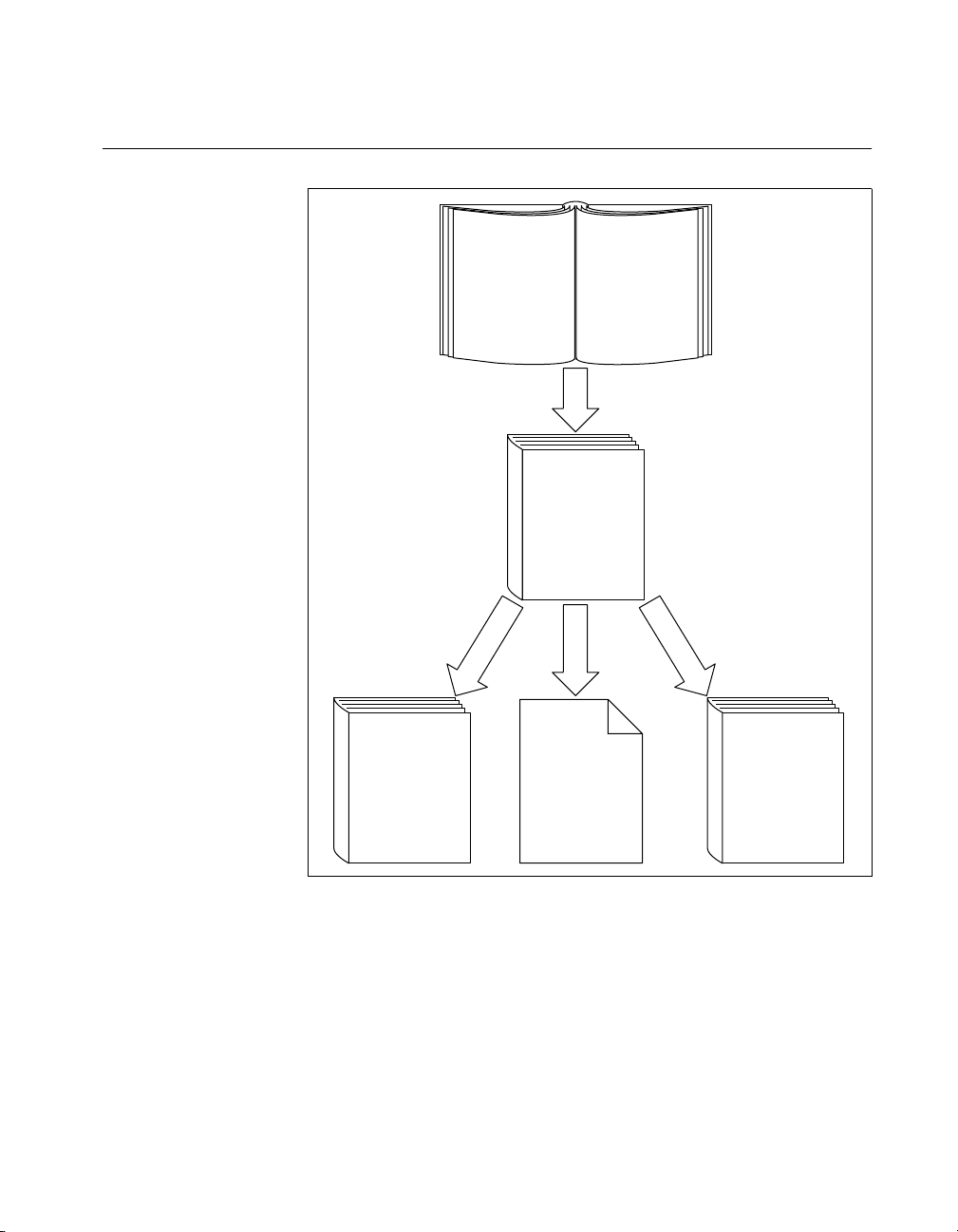
How to Use This Documentation Set
About This Manual
NI-VXI
User Manual
NI-VXI
Reference
Getting Started
Manual
Series User Manual
Change Hardware
Settings (Optional)
NI-VXI and NI-VISA
NI Spy, VIC/VISAIC
Installation and
Configuration
VXI/VMEpc 600
Use Online
Utilities:
Function Help,
T&M Explorer,
NI-VISA
User Manual
NI-VISA
Reference
Begin by reading this manual, Getting Started with Your VXI/VMEpc 600
Series for Windows 95/NT, to get basic instructions for setting up the
hardware and software. This brief quick- start manu al describes ho w to get
started with your kit using the default hardware and software settings. Refer
to the following manuals for more information about the hardware or
software.
©
National Instruments Corporation ix VXI/VMEpc 600 Series for Windows 95/NT
Page 10

About This Manual
The VXI/VMEpc 600 Series User Manual contains more details about
changing the hardware installation or configuration from the defaults, and
using the hardware.
When you are familiar with the material in these manuals, you can begin to
use the NI-VXI User Manual. This manual presents the concepts of VXI
and prepares you for detailed explanations of the NI-VXI functions. The
NI-VXI online help describes the NI-VXI functions to hel p you fully
understand the purpose and s yntax of each function. Y ou can f ind this same
information in the NI-VXI Programmer Reference Manual. These two
manuals are available in the
NI-VXIUsersMan.pdf and NI-VXIProgrammerMan.pdf,
names
c:\NIVXI\Manuals directory under the
respectively. Use the Acrobat Reader program, Version 3 or later, to open
these files.
You can also access the NI-VXI online help for Windows 95/NT in the
NIVXI folder.
Refer to the NI-VXI Graphical Utilities Reference Manual and the NI-VXI
Text Utilities Reference Manual to learn more about the NI-VXI utilities.
Refer to the NI-VISA User Manual to learn about VISA and how to use it
in your system. The NI-VISA online help describes the attributes, events,
and operations you can us e in NI-VISA. You can find this same i nformation
in the NI-VISA Programmer Reference Manual. These two manuals are
available in the
Win95 or WinNT) under the names NI-VISAUsersMan.pdf and
either
NI-VISAProgrammersMan.pdf, respectively. Use the Acrobat Reader
c:\Vxipnp\os\NIvisa\Manuals directory (where os is
program, Version 3 or later, to open these files.
Related Documentation
The followi ng documents contain i nformatio n that you may fin d helpful as
you read this manual:
• ANSI/IEEE Standard 1014-1987, IEEE Stan dard for a Versatile
Backplane Bus: VMEbus
• ANSI/IEEE Standard 1155-1993, IEEE VMEbus Extensions for
Instrumentation: VXIbus
• ANSI/VITA 1-1994, VME64
• VXI-6, VXIbus Mainframe Extender Specification, Rev. 1.0, VXIbus
Consortium
VXI/VMEpc 600 Series for Windows 95/NT x
©
National Instruments Corporation
Page 11

Customer Communication
National Instruments wants to receive your comments on our products
and manuals. We are interested in the applications you develop with our
products, and we want to help if you have problems with them. To make it
easy for you to contact us, thi s manual contains comment and conf iguration
forms for you to complete. These forms are in Appendix D, Customer
Communication, at the end of this manual.
About This Manual
©
National Instruments Corporation xi VXI/VMEpc 600 Series for Windows 95/NT
Page 12

Introduction
This chapter describes the VXI/VMEpc 600 Series of emb edded computers
along with the NI-VXI/VISA software, lists what you need to get started,
lists optional soft ware, and gi ves an overvi ew of th e director y str uctur e on
your hard drive.
How to Use This Manual
The following flowchart shows where to turn in this man ual for more
details on configuring and using the hardware and software.
1
Chapter 1
Chapter 2
Chapter 3
Gather What You Need
to Get Started
Yes
Using Hardware
Defaults?
Install Hardware, Verify System,
Run T&M Explorer to Configure
All Devices in System
Develop Y our Application
What You Need to Get Started
❑ VXI/VMEpc-650 embedded controller
❑ VXIbus or VMEbus mainframe
❑ Keyboard (and included adapter cable)
❑ Mouse
No
Refer to Your
VXI/VMEpc 600
Series User Manual
©
National Instruments Corporation 1-1 VXI/VMEpc 600 Series for Windows 95/NT
Page 13

Chapter 1 Introduction
❑ Monitor with VGA or better resolution
❑ National Instruments software media for the VXI/VMEpc 600 Series
The NI-VXI/VISA software is alr eady inst alled on your VXI/VME pc-650
computer. It is also included on disk in the event that you need to reinstall
your software. For installation instructions, please refer to Appendix C,
Reinstalling the NI-VXI/VISA Software.
Hardware Description
The VXI/VMEpc 600 Series models are B-size embedded co mputers based
on x86 processor architecture and on the Peripheral Component Interface
(PCI) bus. These computers are high-performance, easy-to-use platforms
for controlling VXIbus or VMEbus systems, featuring complete VXI and
VME functionality through interactive utilities and C fun c tion calls.
These embedded computers can take advantage of the VXI/VME
high-performance backplane capabilities and give you direct control of
VXI/VME registers, memory, interrupts, and triggers.
All models in the VXI/VMEpc 600 Series are fully VXI
compliant and can be used with PC-compatible software tools, the
National Instruments LabVIEW and LabWindows/CVI application
software, and the NI-VXI, NI-VISA, and NI-488.2 bus interface software.
For in-depth details on the VXI/VMEpc 600 Series hardware—including
a description of the differences between the various models in their
respective series—refer to the VXI/VMEpc 600 Series User Manual.
Software Description
NI-VXI is the name of the VXI/VME bus control library for your
VXI/VMEpc 600 Series. You can create applications using NI-VXI to
control your VXI and VME devices. NI-VXI gives you complete
VXI/VME functionality, including an API for performing basic VXI/VME
data transfers and handling VXI/VME interrupts as well as VXI-specific
functionality, such as doing message-based communication and handling
VXIbus triggers.
NI-VISA is the National Instruments implementation o f the VISA
specification. VISA is a uniform API for communicating and controlling
Serial, GPIB, VXI, and VME instruments. This API aids in the creation of
more portable applications and instrument drivers.
plug&play
VXI/VMEpc 600 Series for Windows 95/NT 1-2
©
National Instruments Corporation
Page 14

Chapter 1 Introduction
The NI-VXI/VISA software for the VXI/VMEpc 600 Series is already
installed on your hard drive. It includes an interactive configuration and
troubleshooting program, libraries of software routines for test and
measurement (T&M) programming, interactive control programs for both
NI-VXI and NI-VISA, a logging utility you can use for debugging your
applications, and a VXI Resource Manager. You can use this software to
seamlessly program multiple-mainframe configurations and have software
compatibility across a variety of controller platforms.
National Instruments also includes the NI-488.2 software kit, which gives
you access to the industry-standard NI-488.2 software for controlling
external GPIB instruments through the GPIB port on the front panel. The
GPIB interface on your VXI/VMEpc controller is fully compatible with the
NI-488.2 driver for a variety of operating systems. Any software using
NI-488.2 will run on the VXI/VMEpc-650.
Use T&M Explorer to view your entire T&M system and configure v arious
components, whether they are Serial, GPIB, VXI, or VME devices. This
utility also adopts the functionality of the NI-DAQ Configuration utility so
you can configure National Instruments VXI-DAQ cards.
For VXI users, T&M Explorer also features various options of how to run
the VXI Resource Manager (Resman). You can still execute Resman
independently to configure your instruments after a power cycle, but you
can also perform resource manager operations directly from T&M Explorer
or configure it to run Resman automatically at startup.
The NI Spy utility tracks the calls your application makes to National
Instruments T&M drivers, including NI-VXI, NI-VISA, and NI-488.2.
NI Spy helps you debug your application by clearly highlighting the
functions that return errors. You can let NI Spy keep a log of your
program’s calls to these drivers so that you can check them for errors
at your convenience.
Software Configurations
There are three software configurations described in this manual:
• NI-VXI for Windows 95—This is a fully 32-bit native Plug and P l ay
driver for Windo w s 95. You can run only 32-bit applications with this
driver. Applications developed using this driver run with NI-VXI for
Windows NT without the need to recompile.
• NI-VXI for Windows NT—This is a 32-bit driver designed for
Windows NT. You c an use this version to develop and run 32-bit
applications for Windows 95/NT.
©
National Instruments Corporation 1-3 VXI/VMEpc 600 Series for Windows 95/NT
Page 15

Chapter 1 Introduction
• NI-VISA for Windows 95/NT—This is a 32-bit driver designed for
Windows 95/NT. Note that for VME and VXI support, the NI-VXI
driver must be installed. You can use this driver to develop and run
32-bit applications for Windows 95/NT.
National Instruments Application Software
Your VXI/VMEpc 600 Series kit comes with the NI-VXI/VISA bus
interface software already installed for you. In addition, you can use the
National Instruments LabVIEW and LabWin dows / CVI appli cati on
programs and instrument drivers to ease your programming tasks. These
standardized programs match the modular virtual instrument capability of
VXI/VME and can reduce your VXI/VME software development time.
These programs are fully VXIplug&play compliant and feature extensive
libraries of VXI instrument drivers written to take full advantage of direct
VXI control. LabVIEW and LabWind ows/CVI include all the t ools needed
for instrument control, data acquisition, analysis, and presentation.
LabVIEW is a complete programming environment that departs from the
sequential nature of traditional programming languages and features a
graphical programming environment.
LabWindows/CVI is an interactive C development environment for
building test and measurement and instrument control systems. It includes
interactive code-gener ation tools and a graphical editor for building custom
user interfaces.
When you boot your system for the f irst time, you can insert a configuration
disk to access either or both of these application programming
environments. Ref er to the
in Chapter 2,
Setting up Your VXI/VME System
Booting Your System for the First Time
, for more information. Both
section
LabVIEW and LabWindo ws/CVI integrate the VXI and VISA libraries that
are required to support your VXI/VMEpc-650. You also get hundreds of
complete instrument drivers, which are modular, source-code programs
that handle the communication with your instrument to speed your
application development.
VXI/VMEpc 600 Series for Windows 95/NT 1-4
©
National Instruments Corporation
Page 16

Chapter 1 Introduction
Files and Directories Installed on Your Hard Drive
Your hard drive includes a directory called images in its root that contains
software and soft copies of manuals for the operating system and for the
peripherals. The directory str ucture under the
organized into several levels.
images directory itself, you will find a manuals directory,
In the
os directory, and directories for each of the peripherals of your
an
computer.
manuals directory contains quick reference guides, technical
The
reference manuals, and National Instruments software manuals, all in
Adobe Acrobat portable document for mat (PDF) . Use the Acrobat Reader
program, version 3 or later, to open and read these manual files on your
computer, and to print them if desired. To access any of these manuals,
change your directory to
c:\images\Vxx600\manuals and list the
contents of that directory.
os directory contains a subdirectory corresponding to the operating
The
system installed on your computer . That subd irectory contains an image o f
the CD from which your operating system was installed. As a result you do
not have to inser t the CD when you install a n e w peripheral. When you a re
asked to insert the CD, you can simply direct the system to look in the
images\os directory instead.
images directory is logically
For example, if your system has Windows 95 installed, you should find
an image of the Windows 95 CD in
c:\images\os\win95.
The rest of the directories correspond to each of the peripherals in
your system. Within each of these directories are the drivers for the
peripherals. These files and directories are copied exactly from the
distribution disks of the manufacturers, so the naming conventions
vary from peripheral to peripheral.
Because the naming conventions may not be completely straightforward,
National Instruments provides a text file named
images directory. The drivers.txt file explains how to install support
drivers.txt in the
for each peripheral. You may want to print this file for reference when yo u
install your peripheral device drivers.
©
National Instruments Corporation 1-5 VXI/VMEpc 600 Series for Windows 95/NT
Page 17

Setting up Your VXI/VME System
This chapter contains basic instructions for setting up the VXI/VMEpc 600
Series and the NI-VXI/VISA software.
You can use this material as a guide to quickly configure and operate your
VXI/VME system using the VXI/VMEpc 600 Series. This chapter assumes
that you intend to perform a basic configuration as follows:
• You have one VXI/VMEbus chassis in which you will be using the
VXI/VMEpc-650 as System Controller.
• You will be using the NI-VXI/VISA software for initialization,
configuration, and device interaction.
• You will use the default hardware and software settings.
Configuring the Hardware
The default hardware settings are acceptable for most typical applications.
Refer to Appendix A, Default Settings, for a complete listing of the
hardware and software default settings.
2
The VXI/VMEpc 600 Series User Manual fully describes the configuration
and installation of each embedded computer in the VXI/VMEpc 600
Series. Refer to this manual if you want to try a different hardware
configuratio n, or if you would lik e more information on a particu lar setting.
Use the T&M Explorer utility in NI-VXI/VISA to change any of the
configuration settings for the VXI/VMEpc. For information on the
software, including optional settings, use T&M Explorer and its online
help. Use the W i ndo ws Start menu to open either the NI-VXI or NI-VISA
program group and select T&M Explorer. To access the T&M Explorer
online help, open the Help menu and select Help Topics.
©
National Instruments Corporation 2-1 VXI/VMEpc 600 Series for Windows 95/NT
Page 18

Chapter 2 Setting up Your VXI/VME System
Installing the Hardware
!
!
Caution
Warning
Caution
To prevent electrostatic discharge, touch the antistatic plastic package to a
metal part of your VXI/VMEbus chassis before removing the VXI/VMEpc-650
from the package.
To protect both yourself and the chassis from electrical hazards, thechassis
should remain off until you are finished installing the VXI/VMEpc module.
Plug in your chassis but leave the power turned off. Install the
VXI/VMEpc-650 in the first slot of the VXI/VME chassis—designated
as Slot 0 in VXI systems, or as Slot 1 in a VME chassis. In its default
configuration, the VXI/VMEpc 600 Series automatically detects whether it
should be the system co ntrolle r. Although you can use the module in other
slots as non-system controller, this example describes the basic installation
as system controller. The system controller operates certain VXI/VMEbus
lines as required for VXI/VME systems. Verify that any other devices with
system controller capability that are located in the same chassis are not
configured as system controller.
Having more than one device configured as system contro ller will damage the
VXI/VME system.
For VXI systems that include VME devices, ensure that the VME devices
are not configured in the upper 16 KB (starting from 0xC000) of the A16
address space. This region is reserved for VXI device configuration
registers, which are used for initializing, configuring, and interacting with
VXI devices.
Also ensure that no VXI devices in your system are config ured for logical
address 0, which is the default configuration for the VXI/VMEpc 600
Series.
Complete your installation as follows:
1. Attach cables for your keyboard, mouse, video, and any devices you
want to connect to your system. Refer to the VXI/VMEpc 600 Series
User Manual if you are not certain about any of these connections.
2. Turn on power to the chassis.
3. Follow the prompts in the Setup program.
VXI/VMEpc 600 Series for Windows 95/NT 2-2
©
National Instruments Corporation
Page 19

Chapter 2 Setting up Your VXI/VME System
Installed Software
Your VXI/VMEpc 600 Series kit comes with the NI-VXI/VISA bus
interface software already installed. However, if you receive a software
update, or if you need to reinstall software in the event that your files were
accidentally erased, refer to Appendix C, Reinstalling the NI-VXI/VISA
Software. This appendix explains how to use the Setup program.
If you need to reinstall LabVIEW or LabWindows/CVI, use the CD or
diskette package that came with these programs.
Booting Your System for the First Time
At Windows 95/NT startup, you are pro mpted t o insert a disk to config ure
the system for LabVIEW or LabWindows/CVI. These programming
environments are already installed on your system but you must insert a
configuration disk when prompted so that you can access and use them. If
you ordered either of these programming environments, select the
appropriate checkbox and insert the configuration disk. Follow the
instructions as prompted.
Do not select either checkbox if you did not order LabVIEW or
LabWindows/CVI. Continue with the rest of the Setup program.
Caution
!
©
National Instruments Corporation 2-3 VXI/VMEpc 600 Series for Windows 95/NT
Do not disregard the prompt to configure the system for LabVIEW or
LabWindows/CVI. The Setup program assumes you do not need these programs
and deletes them from your hard drive unless you insert the configuration disk
during the initial setup. If you neglect to do this, you will need to install LabVIEW
or LabWindows/CVI from the CD or diskette set if you want to use either program.
If your system includes any VXI devices, you s h ould now run T& M
Explorer . It p rompts y ou to r un Resman, whi ch is the National In struments
Resource Manager. You must run Resman every time the chassis power is
cycled so that your application can access devices in the VXI/VME chassis.
You can configure T&M Explorer to automatically run Resman on
power-up. T&M Explorer contains right-click help that leads you through
your configuration tasks.
Whether you are a VXI or VME user, please continue with Chapter 3,
Developing Your Application, for information about using T&M Explorer
in your system.
Page 20

Chapter 2 Setting up Your VXI/VME System
Verifying Your System Configuration
After you finish configuring t he system through T&M Exp lorer, verify t he
system configuration through one of the interactive control utilities. Use
VIC under NI-VXI or VISAIC under NI-VISA.
For an example on how to use VIC, refer to the Device Interaction section
in Chapter 3, Developing Your Application.
VXI/VMEpc 600 Series for Windows 95/NT 2-4
©
National Instruments Corporation
Page 21

Developing Your Application
This chapter discusses the software utilities you can use to start developing
applications that use the NI-VXI/VISA driver.
After verifying your system configuration, you can begin to develop your
VXI/VME or VISA application software. Be sure to check the
README.txt file for the latest application de velo pment notes and changes.
You r software includes several utilities to assist you in your system
development. These include T&M Explorer , Resman, NI Spy , VISAIC, and
VIC. You can also access several examples to learn ho w to use NI-VISA or
NI-VXI for certain tasks. Each of these components assists you with one of
four steps of dev elopment: configur ation, device interact ion, programming,
and debugging.
You can access these utilities through the Windows Start menu. Open
either the NI-VXI or NI-VISA program group and select the utility you
want to use.
3
Configuration
The configuration utilities in your kit are T&M Explorer and Res man.
Resman is the application that performs VXI Resource Manager functions
as described in the VXIbus specification. Its most important functions
include configuring all VXI devices on the VXI/VME backplane for
operation and allocating memory for devices that request it.
Note
©
National Instruments Corporation 3-1 VXI/VMEpc 600 Series for Windows 95/NT
Because power cycling resets all devices, run Resman to reconfigure them every
time chassis power is cycled.
Resman must be run on any system that contains VXI devices (including
systems containing VXI-MXI-2 or VME-MXI-2 mainframe extender
devices). Because VME devices normally do not have configuration
registers as defined in the VXIbus specification, the Resource Manager
is unable to detect VME devices. Because of this, when using systems
containing a mixture of VME devices and VXI devices, you need to
Page 22

Chapter 3 Developing Your Application
manually add your VME devices in T&M Explorer using the Add VME
Device Wizard to reserve system resources when the Resource Manager
runs.
Systems consisting of only a VMEpc 600 Series controller, a VME chassis,
and VME boards do not need to run Res man when usi ng NI-VXI s oftw are
even though the devices do not appear in the T&M Explorer connection
tree. However , you would not be able to use VISA without manually adding
the VME devices to the system by usin g T&M Explorer as described abov e
and then running Resman. This is because NI-VISA uses the Resource
Manager to create instrument sessions for VXI/VME device
communication. If this is not an issue for you, you can skip Resman.
T&M Explorer presents a graphical display of your entire test and
measurement system to help you configure various components. When
you launch T&M Explorer, you see all your VXI, GPIB, GPIB-VXI, and
serial devices on the screen. You can add devices that cannot be detected
dynamically by T&M Explorer through the Add Device Wizard in the
Edit menu. Such devices include VME de vices, certain GPIB de vices, and
serial ports. You can view the properties (such as logical address, address
space used, primary address, and so on) of each device by right-clicking
on the device in the tree. When you view the properties of most National
Instruments devices, you can configure the h ardware settings directly in the
property pages.
T&M Explorer and Resman are designed to work togeth er . You can run the
Resource Manager through T&M Explorer by either clicking on the Run
Resman button on the to olbar, or selecting VXI Resource Manager from
the Tools menu. From th e Op ti o ns dialog in the Tools menu, you can also
configure T&M Explorer to run Resman automatically when the comp uter
boots up. Resman reports all errors that it finds in your system to T&M
Explorer. When you view your system through T&M Explorer, you can
easily spot any errors in your system that Resman found.
You can find more information about T&M Explorer by using its online
help. From T&M Explorer, open the Help menu and select Help Topics.
VXI/VMEpc 600 Series for Windows 95/NT 3-2
©
National Instruments Corporation
Page 23

Device Interaction
After Resman has detected and configured all VXI devices, you can view
specific information on each device in your system by using the T&M
Explorer utility. This utility includes a System View, which contains a
description for each device, including each VXI device’s logical address.
Y ou can interact with your VXI devices by using the VIC or VISAIC utility
(VIC for NI-VXI or VISAIC for NI-VISA). You can use these utilities to
interactively control your devices without having to use a conventional
programming language, LabVIEW, or LabWindows/CVI.
Chapter 3 Developing Your Application
Note
You can launch VIC or VISAIC from the Tools menu in T&M Explorer.
Try the following in VIC:
In the Command entry field, type
help vxiin.
This help file shows you the syntax for this command, which reads VME
address space. The first argu ment is the access parameters for selecting the
address space, byte order, and so on. The second is the VME address to
read, and the third is the width of the data to read.
Type:
vxiin 1,0xC000,2
The History window shows the result of the command execution, such as:
Return Status (0): SUCCESS.
value = 0x9ff6
If the value ends with ff6, you have successfully read the National
Instruments manufacturer ID from the VXI/VMEpc-650 ID register.
Because this is the first configuration register present for all VXI devices,
the VXI device at Logical Address 0 has its manufacturer ID register
located at A16 address 0xC000—the beginning of the VXI configuration
space.
You may now want to read t h e registers from ot her devices in y our s ys te m
using the command
vxiin. Try reading a r egister from each of the de vices
listed in the Address Map View of T&M Explorer. In this way, you can
verify that your VXI/VMEpc-650 can access each of the devices in your
system successfully.
©
National Instruments Corporation 3-3 VXI/VMEpc 600 Series for Windows 95/NT
Page 24

Chapter 3 Developing Your Application
Alternatively, you can use VISAIC to interact with your devices. VISAIC
lists the available devices, similar to what T&M Explorer displays. By
double-clicking on a gi ven device, you can open a VISA session and access
the device through it. For more information regarding VISAIC, use the
right-click help available from all panels.
Programming with VXI
National Instruments provides two different programming interfaces
for accessing your instruments: NI-VISA and NI-VXI. NI-VISA is the
National Instruments implementation of the VISA API as defined by the
VXIplug&play standard. It is very useful when you have different types
of instruments in your system (such as VXI, VME, GPIB, and Serial
devices) because the NI-VISA functions have the same interface.
NI-VXI is the National Instruments proprietary interface for programming
VXI/VME instruments. Both NI-VXI and NI-VISA grant you
register-level access of VXI/VME instruments as well as messaging
capability to message-based devices. With either interface you can service
asynchronous events, such as triggers and interrupts, and also assert them.
The best way to learn how to program with NI-VXI or NI-VISA is by
reviewing the example programs included in your software. In the
Examples directory you will find examples for many different types of
applications. If you are just getting started, you should first learn how to
access registers with high-level calls and send messages with word serial
functions. The NI-VISA examples of these tasks are called
VISAws.c. The NI-VXI examples are called VXIhigh.c and
and
VXIws.c. You should use the other examples as you try more advanced
techniques. Consult th e NI-VISA User Manual or the NI-VXI User Manual
for additional information on these topics.
VISAhigh.c
Note
The NI-VXI User Manual resides in the NIVXI\manuals directory, and the
NI-VISA User Manual is in the
would be either
Win95 or WinNT. Use the Acrobat Reader program to open and
VXIpnp\os\NIvisa\manuals directory, where
navigate through the manuals.
VXI/VMEpc 600 Series for Windows 95/NT 3-4
©
National Instruments Corporation
os
Page 25

Chapter 3 Developing Your Application
Table 3-1 summarizes the topics addressed by the example programs.
Table 3-1.
NI-VXI/VISA Examples
NI-VISA
Coverage
Message-Based Access
High-Level Register
Example
VISAws.c VXIws.c
VISAhigh.c VXIhigh.c
NI-VXI Example
Access
Low-Level Register Access
Sharing Memory
Interrupt Handling
Trigger Handling
Note T&M Explorer includes special settings that you must use for low-level functions
VISAlow.c VXIlow.c
VISAmem.c VXImem.c
VISAint.c VXIint.c
VISAtrig.c VXItrig.c
and memory sharing. Consult the T&M E xp lorer online help for information on
setting these up.
Notes about VME Support
To use VME devices in your system, conf igure NI-VXI to see these devices
by using the Add Device Wizard in T&M Explorer. VME devices with
two blocks of memory in the same address space require two entries. You
can also specify which interrupt levels the device uses. VXI and VME
devices cannot share interrupt le v els. You can then access the VME device
from NI-VXI or NI-VISA just as you would a register-based VXI device,
by specifying the address space and the offset from the base at which you
have configured it. NI-VISA support for VME devices includes the re gister
access operations (both high-level and low-level) and the block move
operations, as well as the ability to receive interrupts.
©
National Instruments Corporation 3-5 VXI/VMEpc 600 Series for Windows 95/NT
Page 26

Chapter 3 Developing Your Application
Compiler Symbols for NI-VXI
You may need to define some symbols so that the NI-VXI library can work
properly with your program.
Note
Note
Skip this section if you are programming with NI-VISA only. NI-VISA does not
use these symbols.
You can define the symbols using
or you can use either the
/D or the -D option in your compiler (both the
Microsoft and Borland compilers support the
#define statements, you must define the symbols before including the
use
NI-VXI header file
nivxi.h. If you use the makefiles to compile the
#define statements in the source code
/D and -D options). If you
sample program, the makefile already defines the necessary symbols.
VXINT symbol is required. You must define it when using the
The
Microsoft C or Borland C compiler.
VXINT designates the application as a
Windows 95/NT application.
LabWindows/CVI automatically defines the correct symbol. You do not need to
VXINT when using LabWindows/CVI.
define
BINARY_COMPATIBLE symbol is optional. It makes the application
The
binary compatible with embedded VXI controllers, such as the National
Instruments VXI/VMEpc series of embedded cont rollers. Th is optio n may
cause a slight performance degradation when using low-level VXIbus
access functions.
If you define these symbols in your source code, your source code should
look something like the following sample code:
#define VXINT
#define BINARY_COMPATIBLE
.
.
.
#include <nivxi.h>
If you define these s ymbols using the /D or -D compiler options, you
should specify the following when invoking the compiler.
For the Microsoft C compiler:
/DVXINT /DBINARY_COMPATIBLE
VXI/VMEpc 600 Series for Windows 95/NT 3-6
©
National Instruments Corporation
Page 27

Debugging
Chapter 3 Developing Your Application
For the Borland C compiler:
-DVXINT; BINARY_COMPATIBLE;
You will also need to link in the appropriate import library for your code.
If you are using a Microsoft C compiler, use the
nivxi\win32\msc\ directory . If you are using a Borland C compiler , use
nivxint.lib in the nivxi\win32\borlandc\ directory.
the
nivxint.lib in the
Refer to the documentation that came with your compiler package for
detailed instructions about using the compiler and the various tools (linker,
debugger, and so on). Your compiler documentation is an important and
useful source of information for writing, compiling, and debugging C
programs.
NI Spy, VISAIC, and VIC are useful utilities that can aid in identifying the
causes of problems in your appl ication.
NI Spy tracks the calls your application makes to National Instruments
T&M drivers including NI-VXI, NI-VISA, and NI-488.2. NI-488.2 users
may notice that NI Spy is very similar to GPIB Spy. It highlights functions
that return errors, so you can quickly spot which functions failed during
your development. NI Spy can log the calls your program makes to these
drivers so you can check them for errors at your convenience.
Y ou can also control your instrumen ts interactively using VISAIC and VIC.
You can use VISAIC to control and communicate with your instruments
with NI-VISA without having to write a program. VIC gives you a similar
environment that uses NI-VXI. These utilities are an excellent platform for
quickly testing instruments and learning how to communicate with them.
Refer to the online help for instructions on how to use VIC or VISAIC and
to learn about their features. In VIC, click on the ? button (next to the
Go button) to get help for that page, or you can type
help. You can also
right-click on a component on the screen to access What’s This help. In
VISAIC, you can right-click to reach What’s This help and function help.
©
National Instruments Corporation 3-7 VXI/VMEpc 600 Series for Windows 95/NT
Page 28

Default Settings
This appendix summarizes the default settings for th e hardware and
software in your kit. If you need more information about a particular
setting, or if you want to try a different configuration, please refer to the
VXI/VMEpc 600 Series User Manual for your hardware reference and the
T&M Explorer online help for your software reference.
Because you can also use T&M Explorer to configure a VXI-MXI-2 or a
VME-MXI-2, this appendix also summarizes the software default settings
for the VXI/VME-MXI-2.
VXI/VMEpc 600 Series
This section summarizes the hardware and software default settings for the
VXI/VMEpc 600 Series. Notice that some of the jumpers described in
Table A-1 are for VXI configuration only.
A
Table A-1.
Jumper Description Default Setting Description
W1—Power On MITE Self
Configuration
W2—External Trigger Input
Termination (VXI only)
W3—SCSI Bus Termination Enabled
W4—CLK10 SMB Dire c tion
(VXI only)
W5—CLK10 SMB Termination
(VXI only)
W6—CLK10 Source
(VXI only)
©
National Instruments Corporation A-1 VXI/VMEpc 600 Series for Windows 95/NT
VXI/VMEpc 600 Series Hardware Default Settings
Enabled.
Do not terminate
Receive CLK10
Do not terminate
Source from onboard oscillator
Do not alter this setting
.
Page 29

Appendix A Default Settings
Table A-1.
VXI/VMEpc 600 Series Hardware Default Settings (Continued)
Jumper Description Default Setting Description
W7—CLK10 SMB Pola rity
Not inverted
(VXI only)
W8—Ethernet EEPROM Enabled. Do not alter this setting.
W9—MITE User Conf iguration
Load values from user side
EEPROM
W11—System Controller Slot
Automatically detect slot
Detection Mode
W20—Clear CMOS Disabled. Change only when
clearing CMOS.
Table A-2.
VXIpc T&M Explorer Device Tab Default Settings
Editor Field Default Setting
Logical address 0
Device class Message based
Size of Servant area 0
Number of handlers 1
Number of interrupters 0
Table A-3.
VXIpc T&M Explorer Shared Memory Tab Default Settings
Editor Field Default Setting
Memory sharing Don’t share memory
Shared RAM size 64 KB (when sharing memory)
Reserved physical memory 64 KB (when sharing memory)
Lower half window byte
swapping
VXI/VMEpc 600 Series for Windows 95/NT A-2
Disabled
©
National Instruments Corporation
Page 30

Appendix A Default Settings
VXI/VME-MXI-2
Table A-3.
VXIpc T&M Explorer Shared Memory Tab Default Settings (Continued)
Editor Field Default Setting
Upper half window byte
Disabled
swapping
Map upper and lower halves at
Disabled
same PCI address
Table A-4.
VXIpc T&M Explorer PCI Tab Default Settings
Editor Field Default Setting
Low-level register access API
Enabled
support
User window size 64 KB
This section summarizes the software default settings for the VXI-MXI-2
and VME-MXI-2. This information is useful if you have either of these
modules in your system.
Table A-5.
VXI/VME-MXI-2 T&M Explorer Device Tab Default Settings
Editor Field Default Setting
Logical address Use DIP switch
Address space A24 *
Requested memory 16 KB *
A24/A32 write posting Disabled
A16 write posting Disabled
Interlocked mode Disabled
* Assumes no DRAM is installed. If DRAM is installed, the
A32, and
DRAM yourself, you must manually specify these changes.
©
National Instruments Corporation A-3 VXI/VMEpc 600 Series for Windows 95/NT
Requested memory
should match the amou nt of DRAM. If you install the
Address space
should be
Page 31

Appendix A Default Settings
Table A-6.
VXI/VME-MXI-2 T&M Explorer VXI/VME Bus Tab
Default Settings
Editor Field Default Setting
Bus timeout value 125 µs
Slot 0 configuration Auto-detect
Auto retry Disabled
Transfer limit 256
Arbiter type Priority
Fair requester Enabled
Arbiter timeout Enabled
Request level 3
Table A-7.
VXI/VME-MXI-2 T&M Explorer MXI-2 Bus Tab Default Settings
Editor Field Default Setting
System controller Auto-detect
Bus timeout value 1 ms
MXI-2 auto retry Disabled
MXI transfer limit Unlimited
MXI fair re quester Disabled
Perform parity checking Enabled
MXI-2 CLK10 signal dire ction Switch determines signal
VXI/VMEpc 600 Series for Windows 95/NT A-4
direction (VXI-MXI-2 only)
©
National Instruments Corporation
Page 32

Common Questions
This appendix addresses common questions yo u may have about using th e
NI-VXI/VISA software on the VXI/VMEpc platform.
What are some of the differences between the old utilities and the new
ones?
The old utility components are as follows:
• VXIinit—This utility initializes your National Instruments controller
hardware with settings determined in VXIedit.
• Resman—This utility initializes and configures all the other devices in
your VXI system.
• VXIedit—This utility configures your National Instruments hardware.
• VXItedit—This is a console-based version of VXIedit.
• VIC—Use this utility to interactively communicate with VXI devices
over the VXIbus using the NI-VXI API.
• VICtext—This is a console-based version of VIC.
• VISAconf—This utility configures settings used by NI-VISA
• VISAIC—Use this utility to interactively communicate with VISA
devices (GPIB, VXI, Serial) using NI-VISA.
B
VXI/VME system integration with the old utilities typically proceeded as
follows:
1. Install components and boot the system.
2. Configure your hardware with VXIedit.
3. Reboot and run VXIinit to initialize your National Instruments
hardware.
4. Run Resman to initialize the VXIbus.
5. Optionally run VXIedit to configure any extender devices on the
VXIbus.
6. Run VIC to verify device operation.
7. If you are using VISA, you have the option of running VISAconf to
configure NI-VISA.
©
National Instruments Corporation B-1 VXI/VMEpc 600 Series for Windows 95/NT
Page 33

Appendix B Common Questions
8. Run VISAIC to verify that you can communicate with your system
using VISA.
The new utility components are as follows:
• T&M Explorer—Use this utility to configure, view, and initialize your
system.
• Resman—You can still use this as before. However, you can perform
resource manager operations directly from T&M Explorer or
configure it to run Resman automatically at startup. See What about
running Resman? later in this section.
• VIC—Use as before.
• VISAIC—Use as before.
• NI Spy—Use this utility to debug your NI-VXI or NI-VISA
application.
You r setup might now include the following steps:
1. Install components and boot the system.
2. Execute VXI Resource Manager responsibilities (either run Resman or
click the build button in T&M Explorer.)
3. Run VIC or VISAIC to verify communication in your system.
What happened to VXIinit?
You no longer need to run VXIinit to initialize settings on your ha rdware.
The loading of hardware settings no w takes place in th e dri v er, completely
eliminating the need for VXIinit.
Where do I find the information that VXIinit used to print?
You can view information about your controll er from the properties pages
and the hardware configuration pages. For example, you can view logical
address and user window size in the device-specific property pages in T&M
Explorer .
What happened to VXIedit and VISAconf?
The functionality of these two configuration utilities has been integrated
into a powerful new utility called T&M Explorer. This utility starts with a
graphical view of the VISA devices (GPIB, VXI, GPIB-VXI, and serial)
that it finds in your system. Right-click on an individual device in the tree
structure to see its properties. You can further configure National
Instruments devices by selecting the Hardware Configuration option.
VXI/VMEpc 600 Series for Windows 95/NT B-2
©
National Instruments Corporation
Page 34

Appendix B Common Questions
This includes National Instruments VXI-DA Q car ds, which means you can
configure these devices from T&M Explorer without having to run the
DAQ Configuration Utility.
What about ru nning Resman?
Resman is the name of the utility that performs the duties of a VXI
Resource Manager as discussed in the VXIbus specification. When you
set a National Instruments controller to Logical Address 0, you will at some
point need to run Resman to configure your VXI instruments. If your
controller uses a different (non-zero) logical address and is a
message-based device, you need to start Resman before running it on the
Logical Address 0 computer.
So when do you need to run Resman?
Run Resman whenever you need to configure your VXI instruments. For
example, if you power-c ycle your VXI/VME chassis, your instruments will
be reset, and you will need to run Resman to configure them. You can get
into trouble if you run Resman when your devices are not in a reset state.
Therefore, if you ha ve to run Resman after running it once, you sh ould reset
all of your VXI instruments.
Systems consisting of only a VMEpc 600 Series controller, a VME chassis,
and VME boards do not need to run Res man when usi ng NI-VXI s oftw are
even though the devices do not appear in the T&M Explorer connection
tree. However , you would not be able to use VISA without manually adding
the VME devices to the system by usin g T&M Explorer as described abov e
and then running Resman. This is because NI-VISA uses the Resource
Manager to create instrument sessions for VXI/VME device
communication. If this is not an issue for you, you can skip Resman.
You can perform resource manager operations from wit hin T&M Explorer .
Additionally, you can tell T&M Explorer to run Resman when the
computer first boots up. In this case you may never need to run Resman
explicitly again. You can configure the computer to run Resman at startup,
so when you power the chassis, Resman runs. If you power-cycle the
chassis, the PC reboots, forcing Resman to run again.
How do I handle VME devices?
Although there is no way to auto matically detect VME de vices in a system,
you can add them easily through the Add Device Wizard in T&M
Explorer. Through this procedure, you can reserve resources for each of
your VME devices and configure T&M Explorer to show VME devices
on the screen with all your other devices.
©
National Instruments Corporation B-3 VXI/VMEpc 600 Series for Windows 95/NT
Page 35

Appendix B Common Questions
How can I determine which version of the NI-VXI/VISA software I
have installed?
Following are several ways to find this information:
• From T&M Explorer, select About... from the Help menu. In the
About dialog box, press the Software Info button. This displays
version information on NI-VXI and NI-VISA files.
• Under Windows 95 and Windows NT 4.0, you can find version
information by right-clicking on any component and selecting the
Properties option. This displays a property sheet wi th a version tab.
This tab has version information about the product (NI-VXI) and th e
component (
NIVXINT.DLL, for example).
• You can find version information ab out th e NI-VXI d river b y ru nni n g
the VIC utility program. Type
ver at the prompt, and the utility
displays the versions of VIC and NI-VXI, and the latest VXI/VMEpc
hardware revision that this NI-VXI driver supports.
• You can find version information about the VISA driver through
VISAIC by selecting About... from the Help menu.
How can I determine the serial number and hardware revision of the
VXI/VMEpc embedded computers?
Run T&M Explorer and right-cl ick on the name of the VXI/VMEpc. Sel ect
Hardware Configuration, and T&M Explorer disp lays the dialog box for
the device. The title bar includes the serial number and hardware revision.
Which NI-VXI utility program must I use to configure the
VXI/VMEpc 600 Series?
Use the T&M Explorer program to configure the VXI/VMEpc.
T&M Explorer is located in the
Which NI-VXI utility program must I use to initialize the
VXI/VMEpc 600 Series?
In Windo ws 95/NT, the VXI/VMEpc embedded computer is automatically
initialized at system startup.
Which NI-VXI utility program must I use to perform startup Resource
Manager operations?
Use the Resman program to perform startup Resource Manager operations.
It is located in the
NIVXI directory . Resman uses the settings configur ed in
T&M Explorer. It initializes your VXI/VMEbus system and stores the
VXI/VMEpc 600 Series for Windows 95/NT B-4
NIVXI program group folder.
©
National Instruments Corporation
Page 36

Appendix B Common Questions
information that it collects to the RESMAN.TBL file in the TBL subdirectory
NIVXI directory.
of the
You can also run Resource Manager operations from T&M Explorer.
Through T&M Explorer, you can also configure Resman to run
automatically at computer startup.
What can I do to make sure that my system is up and ru nning?
The fastest method for testing the system is to run Resman . This p r ogram
attempts to access memory in the upper A16 address space of each device
in the system. If Resman does not report any problems, the VXI/VME
communication system is operational.
To test individual devices, you can use the VIC or VISAIC program
to interactively issue NI-VXI functions or NI-VISA operations,
respectively. You can use the
VXIinReg() and VXIoutReg() functions to t est register- based devices by
VXIin() and VXIout() functions or the
programming their registers. If you have any message-based devices, you
can send and receive messages with the
Notice that
you can use
VXIinReg() and VXIoutReg() are for VXI devices only, but
VXIin() and VXIout() for both VXI and VME.
WSwrt() and WSrd() functions.
Finally, if you are using LabVIEW or LabWindows/CVI and you have
instrument drivers for the devices in your chassis, you can use the
interactive features of these programs to quickly test the functionality of the
devices.
What do the LEDs on the front of the VXI/VMEpc 600 Series mean?
Refer to Appendix B, LED Indicators, i n your VX I/VMEpc 600 Series User
Manual, for a description of the front panel LEDs.
Is something wrong if the red SYSF and FAIL LEDs stay lit after
booting the VXI/VMEpc 600 Series?
If either the SYSF or FAIL LED remains lit, refer to Appendix B, LED
Indicators, in your VXI/VMEpc 600 Series User Manual, for
troubleshooting steps.
Can I access 32-bit registers in my VXI/VMEbus system from the
VXI/VMEpc 600 Series?
Yes. The VXI/VMEpc uses the 32-bit PCI bus to interface to the
VXI/VMEbus. In fact, its VXI/VMEbus circuitry also supports the new
VME64 standard for D64 accesses.
©
National Instruments Corporation B-5 VXI/VMEpc 600 Series for Windows 95/NT
Page 37

Appendix B Common Questions
♦ VXI Only—CLK10 is a differential ECL signal on the backplane.
♦ VXI Only—The CLK10 signal generated by the VXIpc-6 50 is ±100 ppm
What kind of sig nal is CLK1 0 and what k ind of signal do I need f or an
external CLK10?
However, the oscillator and the EXTCLK input on the front panel use TTL
levels; therefore, you need to supply a TTL-level signal for EXTCLK. Our
voltage converters convert the signal to differential ECL.
What is the accuracy of the CLK10 signal?
(0.01%) as per the VXIbus specification. If you need a more accurate
CLK10 signal, you can use the e xternal C LK connect o r on th e fron t panel.
What type of video interface is onboard the VXI/VMEpc-650? What
video drivers are included? If my application requires a special type of
video display, how do I configure my VXI/VMEpc-650?
The VXI/VMEpc 600 Series uses the Cirrus Logic CL-GD5446 chip, a
64-bit graphics accelerator . The chip is compatible with the Standard VGA
video output Microsoft Windows video driver, as well as the Cirrus Logic
video driver. For more informati on on the video driver, refer to the
c:\images\manuals directory.
What kind of monitor can I use with the VXI/VMEpc 600 Series?
Can I use Super VGA?
VXI/VMEpc 600 Series computers use Super VGA video output. They
work only with monitors having a horizontal scan rate of at least 50 kHz
and a vertical scan rate of 60 Hz.
Caution Make sure your monitor meets this specification. Enabling the Super VGA option
!
on a monitor that does not meet this sp ecification will damage your monitor.
What should I do if my keyboard connector does not fit into the
keyboard port on the VXI/VMEpc-650?
You can plug keyboards that have a 6-pin Mini DIN PS/2 type connector
directly into the VXI/VMEpc. You can use the keyboard adapter cable that
is included with every VXI/VMEpc 600 Series kit to adapt the larger AT
keyboard connector to the 6-pin Min i DIN connector.
©
VXI/VMEpc 600 Series for Windows 95/NT B-6
National Instruments Corporation
Page 38

Appendix B Common Questions
What must I do if I want to install the VXI/VMEpc-650 in a slot other
than the System Controller slot?
The VXI/VMEpc 600 Series automatically detects whether it is in the
System Controller slot (firs t slot) of a VXI/VMEbus mainfra me. Y ou do n ot
need to change jumper settings to install the VXI/VMEpc controller in a
different slot unless you have defeated the f irst slot detector (FSD) circuitry
by changing the appropriate jumper setting on the VXI/VMEpc.
Remember that devices in all other slots must not be manually configured
as system controller; they should be configured either for automatic
detection or manual non-System Controller.
Refer to Chapter 3, Configu ratio n and Instal latio n, in the VXI/VMEpc 600
Series User Manual for information on enabling and defeating the FSD
circuitry.
How do I check the configuration of the memory, floppy drive, hard
drive, time/date, and so on?
Y o u can view these parameters in the BIOS setup. T o enter the BIOS setup,
reboot the VXI/VMEpc controller and press the <DEL> key during the
memory tests. Refer to Chapter 4, BIOS, in the VXI/VMEpc 600 Series
User Manual for more information.
Can I upgrade my VXI/VMEpc 600 Series?
You can upgrade the CPU to 233 MHz if you have the 166 MHz model.
Contact National Instruments for information.
Can I use the internal IDE drive and an external SCSI hard drive at
the same time?
Y es, b ut you can only boot from the inte rnal IDE drive i n this configurat ion.
My CMOS is corrupted. How do I set it back to default?
1. Enter the BIOS setup program as described in Chapter 4, BIOS, in
your VXI/VMEpc 600 Series User Manual.
2. Select Auto Configuration with Optimal Setting s.
3. Answer Y (Yes) to the verification prompt.
4. Select Save Settings and Exit.
©
National Instruments Corporation B-7 VXI/VMEpc 600 Series for Windows 95/NT
Page 39

Reinstalling the NI-VXI/VISA
Software
This appendix conta ins the instru ction s on how to reinstall you r
NI-VXI/VISA software. Your VXI/VMEpc 600 Series controller was
shipped with the NI-VXI/VISA software already installed. It is unlikely
that you will ever need to use these instructions.
Preparing for Installation
Use the Setup program that came with your NI-VXI/VISA software to
install the entire software package or a softwa re update, or to rein stall
software in the e vent that you r files were accidentally erased. The Setup
program works in the sam e manne r fo r eithe r Windo w s 95 or
Windows NT. You can install NI-VXI with or wi thout NI-VISA .
C
Note
©
National Instruments Corporation C-1 VXI/VMEpc 600 Series for Windows 95/NT
Some of the utilities rely on the LabWindows/CVI Run-Time Engine. This
software is installed, if necessary, during the NI-VXI/VISA installation.
Depending on the type of installation you choose, you may need up
to 20 MB of free space available to accommodate the NI-VXI/VISA
software. If you choose the Custom installation method, Setup displays
the amount of memory required for the op tions you se lect.
To be compliant with VXIplug&play specifications, a VXI controller
must provide the VISA I/O driver library standardize d by
VXIplug&play. VISA ensures th at you r control ler can run all
VXIplug&play-compatible software now and in the future.
The NI-VISA software in this kit is compatible with the
WIN95/GWIN95 and WINN T/GW INNT fr amewor ks. With NI-VI SA
installed on your computer, you can ru n any VXIplu g&play software
that is compatible with these frameworks. This includes instrument
drivers and executable soft front panels that are included with
VXIplug&play-compatible instruments f rom a variety of v end ors.
Page 40

Appendix C Reinstalling the NI-VXI/VISA Software
Installing the Software
This section describes how to install the 32-bit NI-VXI/VISA software
for the VXI/VME pc 600 Seri es. T he Setu p progra m work s the same
whether you are using Windows 95 or Windows NT. Plea se carefully
read these directions a long with a ny me ssage s o n the screen be fore
making your selectio ns.
You can quit the Setup program at any time by pr essing the Cancel
button.
Setup is an interactive, self-guiding program that installs the
NI-VXI/VISA software and c onfigur es your system to u se the so ftwar e
with the VXI/VMEpc-650. Follow these steps to perform the
installation:
1. Insert disk 1 of your set of disks labeled NI-VXI/VISA for
VXI/VMEpc 600 Series and Window s 9 5/NT.
2. Select Run... from the Start menu and enter the following text,
X
where
X
and press <Enter>.
3. Click on the Next button at the Welcome screen to start the
installation and accept the license agreement.
is your floppy drive ( usually A)
:\setup.exe
Note
Caution
!
VXI/VMEpc 600 Series for Windows 95/NT C-2
If Setup detects a 16-bit (DOS or Windows 3.x) version of the NI-VXI software,
it prompts you to remove it. Setup will quit so you can uninstall the old software.
If you have a previous 32-bit (Windows 95 or Windows NT) version of the
NI-VXI software installed, Setup installs the new version over the previous
version.
If you want to keep the manufacturer/model name tables or the VME device
configuration from a previous installation, be sure to back them up before starting
Setup, by copying the
4. Select the type of installation from the Choose Setup screen:
• Express setup is the fastest and simplest installation option.
• Typical setup prompts you to make high-level choices of which
TBL directory into another folder.
This option installs all the NI-VXI/VISA software in default
directories without prompting you to make any further choices.
drivers to install and the destination directories.
©
National Instruments Corporation
Page 41

Appendix C Reinstalling the NI-VXI/VISA Software
• Custom setup gives you complete control over which files and
utilities you want installed on your system. This option is
recommended for a dvanc e d us ers.
5. The Express setup completes without further questions. Follow
the prompts if you select either the Typical or the Custom setup
options. The final p rompt d is play s the c ho ices y ou ma de
concerning applications, supp ort, and destination dir ector ies.
Click on the Next button to begin the installation.
6. Setup now copies the necessary files to your hard drive and creates
program icons.
Completing the Software Installation
After Setup completes, please review the information in any README
files that Setup prompts you to rea d. Comple te you r s oftwa re
installation as follows:
1. When the installation process comp letes, y ou must re bo ot your
computer for the changes to take effect. The NI-VXI driver is
loaded at this time.
2. If you backed up the manufacturer and model na me files, restore
them to the
running T&M Explore r.
3. After you install the NI-VXI/VISA software, run the T&M
Explorer program. It will prom pt you to run R esman , the N ational
Instruments Resource M a nage r. Yo u m ust r un Re sman e ve ry time
the chassis power is cycled so that your application can access
devices in the VXI mainframe. You can a lso configure T& M
Explorer to run R es m an a ut om ati cal ly at ev er y c om pute r star t up.
4. After you run Resman, you a re r eady to use T &M Exp lore r to
interactively configure the National Instruments hardware in your
system. Use the right-click help for information about the various
configuration options.
TBL
subdirectory of your NI-VXI direc tory befo re
©
National Instruments Corporation C-3 VXI/VMEpc 600 Series for Windows 95/NT
Page 42

D
Customer Communication
For your convenience, this appendix contains forms to help you gather the information necessary
to help us solve your technical problems and a form you can use to comment on the product
documentation. When you contact us, we need the information on the Technical Support Form and
the configuration form, if your manual contains on e, about your system confi gur at io n to answer your
questions as quickly as possible.
National Instruments has technical assistance through electronic, fax , and telephone systems to quickly
provide the information you need. Our electronic services include a b ulletin board service, an FTP site,
a fax-on-demand system, and e-mai l support. If you ha ve a hard ware or softw are problem, first try the
electronic support systems. If the information available on these systems does not answer your
questions, we of fer fax and tel ephone suppo rt through ou r technical sup port center s, which are staf fed
by applications engineers.
Electronic Services
Bulletin Board Support
National Instruments has BBS and FTP si tes dedicated for 24-hour support with a collection of files
and documents to answer most common customer questions. From these sites, you can also download
the latest instrument drivers, updates, and e xample program s. Fo r recorded instructions on h o w to use
the bulletin board and FTP services and for BBS automated information, call 512 795 6990. You can
access these services at:
United States: 512 7945422
Up to 14,400 baud, 8 data bits, 1 stop bit, no parity
United Kingdom: 01635 551422
Up to 9,600 baud, 8 data bits, 1 stop bit, no parity
France: 01 48 65 15 59
Up to 9,600 baud, 8 data bits, 1 stop bit, no parity
FTP Support
To access our FTP site, log on to our Internet host, ftp.natinst.com, as anonymous and use
your Internet address, such as
documents are located in the
©
National Instruments Corporation D-1 VXI/VMEpc 600 Series for Windows 95/NT
joesmith@anywhere.com, as your password. The support files and
/support directories.
Page 43

Fax-on-Demand Support
Fax-on-Demand is a 24-h our information ret riev al system co ntaining a library of documents on a wide
range of technical information. You can access Fax-on-Demand from a touch-tone telephone at
512 418 1111.
E-Mail Support (Currently USA Only)
You can submit technical support questions to the applications engineering team through e-mail at the
Internet address listed below. Remember to include your name, address, and phone number so we can
contact you with solutions and suggestions.
support@natinst.com
Telephone and Fax Support
National Instruments has branch offices all over the world. Use the list below to find the technical
support number for your countr y. If there is no Na tional Instrume nts office in your country, contact
the source from which you purchased your software to obtain support.
Country Telephone Fax
Australia 03 9879 5166 03 9879 6277
Austria 0662 45 79 90 0 0662 45 79 90 19
Belgium 02 757 00 20 02 757 03 11
Brazil 011 288 3336 011 288 8528
Canada (Ontario) 905 785 0085 905 785 0086
Canada (Quebec) 514 694 8521 514 694 4399
Denmark 45 76 26 00 45 76 26 02
Finland 09 725 725 11 09 725 725 55
France 01 48 14 24 24 01 48 14 24 14
Germany 089 741 31 30 089 714 60 35
Hong Kong 2645 3186 2686 8505
Israel 03 6120092 03 6120095
Italy 02 413091 02 41309215
Japan 03 5472 2970 03 5472 2977
Korea 02 596 7456 02 596 7455
Mexico 5 520 2635 5 520 3282
Netherlands 0348 433466 0348 430673
Norway 32 84 84 00 32 84 86 00
Singapore 2265886 2265887
Spain 91 640 0085 91 640 0533
Sweden 08 730 49 70 08 730 43 70
Switzerland 056 200 51 51 056 200 51 55
Taiwan 02 377 1200 02 737 4644
United Kingdom 01635 523545 01635 523154
United States 512 795 8248 512 794 5678
VXI/VMEpc 600 Series for Windows 95/NT D-2
©
National Instruments Corporation
Page 44

Technical Support Form
Photocopy this form and update it each time y ou make chan ges to your sof tware or har dware, an d use
the completed copy of this form as a reference for your current configuration. Completing this form
accurately before contacting National Instruments for technical support helps our applications
engineers answer your questions more efficiently.
If you are using any National Instruments hardware or software products related to this problem,
include the configuration forms from their user manuals. Include additional pages if necessary.
Name __________________________________________________________________________
Company _______________________________________________________________________
Address ________________________________________________________________________
_______________________________________________________________________________
Fax ( ___ )________________Phone ( ___ ) __________________________________________
Computer brand____________Model ___________________Processor _____________________
Operating system (include version number) ____________________________________________
Clock speed ______MHz RAM _____MB Display adapter __________________________
Mouse ___yes ___no Other adapters installed_______________________________________
Hard disk capacity _____MB Brand_________________________________________________
Instruments used _________________________________________________________________
_______________________________________________________________________________
National Instruments hardware product model_____________ Revision ____________________
Configuration ___________________________________________________________________
National Instruments software product___________________ Version _____________________
Configuration ___________________________________________________________________
The problem is: __________________________________________________________________
_______________________________________________________________________________
_______________________________________________________________________________
_______________________________________________________________________________
_______________________________________________________________________________
List any error messages: ___________________________________________________________
_______________________________________________________________________________
_______________________________________________________________________________
The following steps reproduce the problem: ___________________________________________
_______________________________________________________________________________
_______________________________________________________________________________
_______________________________________________________________________________
_______________________________________________________________________________
Page 45

VXI/VMEpc 600 Series Hardware and Software
Configuration Form
Record the settings and revisions of your hardware and software on the line to the right of each item.
Complete a new copy o f this for m each time you revise your software or hard ware configuration, and
use this form as a reference for your current configuration. Completing this form accurately before
contacting National Instruments for technical support helps our applications engineers answer your
questions more efficiently.
National Instruments Products
NI-VXI/VISA Software Ve rsion N um ber ____________________ ___ _______ ___ ___ ___ ____
Using Both NI-VXI and NI-VISA ? _ _______ ______ __________ ______ _______ ______ ____
Using LabVIEW or LabWin dows/CVI? _______________ ______ __________ ______ ______ _
VXI/VMEpc 600 Series Hardware Settings
VXIpc 600 Series Model Numbe r ____________________ _________ _______ ______ ______ _
Part Number ___________ ______ ___ ____ ___ ______ ____ ___ ___ ______ ____ ___ ___ ______ _
Serial Number __________________ _______ ______ __________ ______ _______ ______ ____
Hard Drive Size ________ _________ _____ Video Memory__________________________ _
Processor Speed _ ____ ______ ___ ___ ____ ______ ___ ____ ___ ______ ___ ____ ___ ______ ___ _
Slot Location _______________________ ___ ______ ____ ___ ___ ______ ____ ___ ___ ______ _
W1 Setting: MITE Self-Configuration ____________ _______ _________ _______ _________ _
W2 Setting: External Trigger SMB Term ina tion ___________________________ ___ ______ _
W3 Setting: SCSI Termination _______________ _______ ______ __________ ______ _______
W4 Setting: CLK10 SMB Direction __________________________________ ______ _______
W5 Setting: CLK10 SMB Term ination __________________ ______ ___ _______ ___ ___ ____
W6 Setting: CLK10 Source ____ _______ _________ _______ _________ _______ _________ _
W7 Setting: CLK10 SMB Polarity __ ____ ______ ___ ____ ______ ___ ___ _______ ___ ______ _
W8 Setting: Ethernet EEPROM ________ ______ _______ _________ _______ ______ ______ _
W9 Setting: MITE Configuration EEPROM _________________ ______ __________ ______ _
W11 Setting: System Controller Slot Detection _______________________________ _______
W20 Setting: CMOS Clea r _______________________________ ___ _______ ___ ___ ___ ____
Page 46

VXI/VMEpc Configuration Editor Settings (T&M Explorer)
Logical Address _______________________________ ____ ___ ___ ______ ____ ___ ___ _____
Device Class __________________ ___ ____ ______ ___ ____ ___ ______ ___ ____ ___ ______ __
Size of Servant Area ____________ ___ ____ ___ ______ ____ ___ ___ ______ ____ ___ ___ _____
Number of Handlers ___ ___ ___ ___ _______ ___ ___ ___ _______ ___ ___ ___ _______ ___ ___ __
Number of Interru pters _______________________ _______ ___ ___ ___ _______ ___ ___ ___ __
Memory Sharing _________________________ ___ ___ ____ ______ ___ ___ ____ ______ ___ __
Shared RAM Size ________________________ ______ __________ ______ _______ ______ __
Reserved Physical Memory ___________________ __________ ______ _______ ______ _____
Lower Half Window B yte Sw apping ____________________________ ___ ____ ___ ______ __
Upper Half Window Byte Swapping __ _______ ______ __________ ______ _______ ______ __
Low-level Register Acce ss AP I Sup por t ___ ___ ___ _______ ___ ___ ___ _______ ___ ___ ___ __
User Window Size _____________ ___ ____ ______ ___ ____ ___ ______ ___ ____ ___ ______ __
VXI/VME-MXI-2 Configuration Editor Settings (T&M Explorer)
Logical Address _______________________________ ____ ___ ___ ______ ____ ___ ___ _____
Address Space _______ _________ _______ ______ _______ _________ _______ ______ _____
Requested Memory _______ ______ ___ ____ ___ ______ ____ ___ ___ ______ ____ ___ ___ _____
A24/A32 Write Posting ____________ __________ _______ ______ ______ __________ _____
A16 Write Posting ________________ __________ _______ ______ ______ __________ _____
Interlocked or Norma l M ode _______________ ___ _______ ___ ___ ___ _______ ___ ___ ___ __
VXI/VME Bus Time out Value ___________ ___ ___ ___ _______ ___ ___ ___ _______ ___ ___ __
Slot 0 Configuration _______________ _______ ___ ___ ____ ______ ___ ___ ____ ______ ___ __
Auto Retry for Cycles f rom VX I/VM Ebus to MXI bus ________ ___ ______ ____ ___ ______ __
Transfer Limit on VXI/VME bus __________________ _______ ______ __________ ______ __
VXI/VME Arbiter Ty pe _________________________ _______ ___ ___ ___ _______ ___ ___ __
VXI/VME Fair Reque ster ____________________ ___ ____ ___ ______ ___ ____ ___ ______ __
VXI/VME Arbiter Tim eo ut ________________ ___ ___ _______ ___ ___ ___ _______ ___ ___ __
VXI/VME Request Leve l _______________ ___ ______ ____ ___ ___ ______ ____ ___ ___ _____
MXI System Controlle r ______ ___ ___ _______ ___ ___ ____ ______ ___ ___ ____ ______ ___ __
MXI Bus Timeout Va lue _____ ___ ___ _______ ___ ___ ____ ______ ___ ___ ____ ______ ___ __
Auto Retry for Cycle s from M XIbu s to VX I/VME bus _____ ______ ___ ___ ____ ______ ___ __
Page 47

Transfer Limit on MXIbus ____________________________ ______ __________ ______ ____
MXI Fair Requester _ ___ ______ ___ ____ ___ ______ ____ ___ ___ ______ ____ ___ ___ ______ _
Parity Checking ______________ ___ ____ ___ ______ ____ ___ ___ ______ ____ ___ ___ ______ _
MXI-2 CLK10 Direction (VXI-M XI-2 only) ____________________ _______ ______ _______
Other Products
Computer make and model ________________________________________________________
Microprocessor __________________________________________________________________
Clock frequency or speed __________________________________________________________
Type of video board installed _______________________________________________________
Operating system version __________________________________________________________
Operating system mode ___________________________________________________________
Programming language ___________________________________________________________
Programming language version _____________________________________________________
Other boards in system ____________________________________________________________
Base I/O address of other boards ____________________________________________________
DMA channels of other boards _____________________________________________________
Interrupt level of other boards ______________________________________________________
Page 48

Documentation Comment Form
National Instruments encourages you to comment on the documentation supplied with our products.
This information helps us provide quality products to meet yo ur needs.
Title:
Getting Started with Your VXI/VMEpc™ 600 Series for Windows 95/NT
Edition Date:
Part Number:
Please comment on the completeness, clarity, and organization of the manual.
_______________________________________________________________________________
_______________________________________________________________________________
_______________________________________________________________________________
_______________________________________________________________________________
_______________________________________________________________________________
_______________________________________________________________________________
_______________________________________________________________________________
If you find errors in the manual, please record the page numbers and describe the errors.
_______________________________________________________________________________
_______________________________________________________________________________
_______________________________________________________________________________
_______________________________________________________________________________
_______________________________________________________________________________
_______________________________________________________________________________
_______________________________________________________________________________
May 1998
321882A-01
Thank you for your help.
Name _________________________________________________________________________
Title __________________________________________________________________________
Company _______________________________________________________________________
Address ________________________________________________________________________
_______________________________________________________________________________
E-Mail Address __________________________________________________________________
Phone ( ___ ) __________________________ Fax ( ___ ) _______________________________
Mail to:
Technical Publications
National Instruments Corporation National Instruments Corporation
6504 Bridge Point Parkway 512 794 5678
Austin, Texas 78730-5039
Fax to:
Technical Publications
Page 49

Glossary
Prefix Meanings Value
p- pico 10
n- nano- 10
µ- micro- 10
m- milli- 10
k- kilo- 10
M- mega- 10
G- giga- 10
t- tera- 10
A
A16 space VXIbus address space equivalent to the VME 64 KB short address space.
In VXI, the upper 16 KB of A16 space is allocated for use by VXI de vices
configuration registers. This 16 KB region is referred to as VXI
configuration space.
–12
–9
–6
–3
3
6
9
12
A24 space VXIbus address space equivalent to the VME 16 MB standard addr ess
space
A32 space VXIbus address space equivalent to the VME 4 GB extended address space
address Character code that identifies a specific location (or series of locations) in
memory. In VISA, it identifies a resource.
n
address space A set of 2
memory locations differentiated from other such sets in
VXI/VMEbus systems by six addressing l ines kno wn as addre ss modif iers.
is the number of address lines required to uniquely specify a byte location
n
in a given space. Valid numbers for n are 16, 24, and 32. In VME/VXI,
because there are six address modifiers, there are 64 possible address
spaces.
address window A portion of address space that can be accessed from the application
program
©
National Instruments Corporation G-1 VXI/VMEpc 600 Series for Windows 95/NT
Page 50

Glossary
ANSI American Nationa l Standards Institute
API Application Programming Interface; the direct interface that an end user
sees when creating an application
ASIC application-specific integrated circuit
B
Bbytes
backplane An assembly, typ ically a printed circuit board, with 96 -pin con nector s and
signal paths that bus the connector pins. A C-size VXIbus system will ha ve
two sets of bused connectors called J1 and J2. A D-size VXIbus system will
have three sets of bused connectors called J1, J2, and J3.
BERR* Bus error signal
BIOS Basic Input/Output System. BIOS functions are the fundamental level of
any PC or compatible computer. BIOS functions embody the basic
operations needed for successful use of the computer’ s hardware resources.
BTO See Bus Timeout Unit.
bus error An error that signals failed access to an address. Bus errors occur with
low-level accesses to memory and usually involve hardware with bus
mapping capabilities. For example, nonexistent memory, a nonexistent
register, or an incorrect device access can cause a bus error.
Bus Timeout Unit A functional module that times the duration of each data transfer
and terminates the cycle if the duration is excessive. Without the
termination capability of this module, a bus master attempt to access a
nonexistent slave could result in an indefinitely long wait for a slave
response.
byte order How bytes are arranged within a word or how words are arranged within a
longword. Motorola ordering stores the mo st significant (MSB) byte or
word first, followed by the least significant byte (LSB) or word. Intel
ordering stores the LSB or word first, followed by the MSB or word.
©
VXI/VMEpc 600 Series for Windows 95/NT G-2
National Instruments Corporation
Page 51

Glossary
C
CLK10 A 10 MHz, ±100 ppm, individually buffered (to each module slot),
differential ECL system clock that is sourced from Slot 0 of a VXIbus
mainframe and distributed to Slots 1 through 12 on P2. It is distributed to
each slot as a single-source, single-destination signal with a matched delay
of under 8 ns.
CMOS Complementary Metal Oxide Semiconductor; a process used in making
chips
Commander A message-based device that is also a bus master and can control one or
more Servants
configuration registers A set of registers through which the system can identify a module device
type, model, manufacturer, address space, and memory requirements. In
order to support au to mat i c s ys tem an d memory configu rat i on, t he VXIbus
specification requires that all VXIbus devices have a set of such registers.
D
Data Transfer Bus DTB; one of four buses on the VMEbus backplane. The DTB is used by a
bus master to transfer binary data between itself and a slave device.
DMA Direct Memory Access; a method by which data is transferred between
devices and internal memory without intervention of the central processing
unit
DRAM Dynamic RAM (Random Access Memory); storage that the computer must
refresh at frequent intervals
driver window A region of address space that is decoded by the VXI/VMEpc for use by the
NI-VXI software
DTB See Data Transfer Bus.
E
ECL Emitter-Coupled Logic
EEPROM Electronically Erasable Programmable Read Only Memory
©
National Instruments Corporation G-3 VXI/VMEpc 600 Series for Windows 95/NT
Page 52

Glossary
embedded controller An intelligent CPU (controller) interface plugged directly into the VXI
backplane, giving it direct access to the VXIbus. It must have all of its
required VXI interface capabilities built in.
F
fair requester A VXIbus device that will not arbitrate for the VXIbus after releasing it
until it detects the bus request signal inactive. This ensures that all
requesting devices will be granted use of the bus.
G
GPIB General Purpose Interface Bus (IEEE 488)
H
hex hexadecimal; the numbering system with base 16, using the digits 0 to 9
and letters A to F
Hz hertz; cycles per second
I
IEEE Institute of Electrical and Electronics Engineers
I/O input/output; the techniques, media, and devices used to achieve
communication between machines and users
instrument driver A set of routines designed to control a specific instrument or family of
instruments , a nd any necessary related files for LabWindows/CVI or
LabVIEW
interrupt A means for a device to request service from another device
interrupt handler A VMEbus functional module that detects interrupt requests generated by
interrupters and r esponds to those req uests by request ing status and identi fy
information
interrupt level The relative priority at which a device can interrupt
IRQ* Interrupt signal
VXI/VMEpc 600 Series for Windows 95/NT G-4
©
National Instruments Corporation
Page 53

Glossary
K
KB kilobytes of memory
L
LED light-emitt ing diode
logical address An 8-bit number that uniquely identifies each VXIbus device in a system.
It defines the A16 register address of a device, and indicates Commander
and Servant relationships.
M
master A functional part of a VME/VXIbus device that initiates data transfers on
the backplane. A transfer can be either a read or a write.
MB megabytes of memory
MBD Message-Based Device
message-based device An intelligent device that implements the defined VXIbus registers and
communication protocols. These devices are able to use Word Serial
Protocol to communicate with one another through communication
registers.
MITE A National Instruments custom ASIC, a sophisticated dual-channel DMA
controller that incorpor ates the Synchronous MXI and VME64 prot ocols to
achieve high-performance block transfer rates
N
NI-488 or NI-488.2 The National Instruments software for GPIB systems
NI-DAQ The National Instruments software for data acquisition instruments
NI-VISA The National Instruments implementation of the VISA standard; an
interface-independent software that provides a unified programming
interface for VXI, GPIB, and serial instruments
NI-VXI The National Instruments bus interface software for VME/VXIbus systems
©
National Instruments Corporation G-5 VXI/VMEpc 600 Series for Windows 95/NT
Page 54

Glossary
Non-Slot 0 device A device configured for installation in any slot in a VXIbus mainframe
other than Slot 0. Installing such a device into Slot 0 can d amage the device,
the VXIbus backplane, or both.
P
PCI Peripheral Component Interconnect. The PCI bus is a high-performance
32-bit or 64-bit bus with multiplexed address and data lines.
PCMCIA Personal Computer Memory Card International Association
POSC Power On Self Configuration
R
RBD Register-Based Device
register-based device A Servant-only device that supports VXIbus configuration registers.
Register-based devices are typically controlled by message-based devices
via device-dependent register reads and writes.
Resman The name of the National Instruments Resource Manager in NI-VXI bus
interface software. See
Resource Manager A message-based Commander located at Logical Address 0, which
provides configuration management services such as address map
configuration, Commander and Servant mappings, and self-test and
diagnostic mana gement
retry An acknowledge by a destination that signifies that the cycle did not
complete and should be repeated
Resource Manager
.
S
s seconds
Servant A device controlled by a Commander; there are message-based and
register-based Servants
Shared Memory Protocol A comm unication p rotoco l th at u ses a b lock of m emory acce ssible to both
a client and a server. The memory block operates as a message buffer for
communications. This is unique to register-based interfaces such as VXI.
©
VXI/VMEpc 600 Series for Windows 95/NT G-6
National Instruments Corporation
Page 55

Glossary
SIMM Single In-line Memory Module
slave A functional part of a VME/VXIbus de vice that detects data transfer cycles
initiated by a VMEbus master and responds to the transfers when the
address specifies one of the device’s registers
SMB Sub Miniature Type B connector that features a snap coupling for fast
connection
System Controller a device configured for installation in Slot 0 of a VXIbus mainframe or
Slot 1 of a VMEbus chassis. This device is unique in the VXI/VMEbus
system in that it performs the VXI/VMEbus System Controller functions,
including clock sourcing and arbitration for data transfers across the
backplane. Installing such a device into any other slot can damage the
device, the VXI/VMEbus backplane, or both.
T
trigger Either TTL or ECL lines used for intermodule communication
TTL Transistor -Transis tor Logi c
U
user window A region of address space reserved by the VXI/VMEpc for use via the
NI-VXI low-level function calls.
space to allocate regions for use by the
macros.
MapVXIAddress() uses this address
VXIpeek() and VXIpoke()
V
VIC VXI Interactive Control Program, a part of the NI-VXI bus interface
software. Used to program VXI devices, and develop and debug VXI
application programs.
VISA Virtual Inst rument Software Architect ure. This is the general name gi ven to
VISA and its associated architecture. The architecture consists of two main
VISA components: the VISA Resource Manager and the VISA Instrument
Control Resources.
©
National Instruments Corporation G-7 VXI/VMEpc 600 Series for Windows 95/NT
Page 56

Glossary
VISAIC VISA Interactive Control Program, a part of the NI-VISA software. Used
to program devices, and develop and debug application programs
VME Versa Module Eurocard or IEEE 1014
VMEbus System
Controller
a device configured for installation in Slot 1 of a VMEbus chassis. This
device is unique in the VMEbus system in that it performs the VMEbus
System Controller functions, including clock sourcing and arbitration for
data transfers across the backplane. Installing such a device into any other
slot can damage the device, the VMEbus backplane, or both.
VXIbus VMEbus Extensions for Instrumentation
W
Word Serial Protocol The simplest required communication protocol supported by
message-based devices in a VXIbus system. It utilizes the A16
communication registers to transfer data using a simple polling handshake
method.
write posting A mechanism that signifies that a device will immediately give a successful
acknowledge to a write transfer and place the transfer in a local buff er . The
device can then independently complete the write cycle to the destination.
VXI/VMEpc 600 Series for Windows 95/NT G-8
©
National Instruments Corporation
Page 57

Index
Numbers
32-bit registers, accessing, B-5
A
Add Device Wizard, 3-2
Add VME Device Wizard, 3-2
application development. See developing
applications.
B
BINARY_COMPATIBLE compiler symbol,
3-6 to 3-7
BIOS setup, B-7
booting system for first time, 2-3
bulletin boar d supp ort , D- 1
C
CLK 10 signal, B-6
CMOS corruption, B-7
common questions. See questions about
NI-VXI/VISA software.
compiler symbols for NI-VXI, 3-6 to 3-7
configuration
booting system for first time, 2-3
configuration utilities, 3-1 to 3-2,
B-1 to B-2
configuring system for LabVIEW or
LabWindows/CVI, 2-3
device interaction, 3-3 to 3-4
hardware configuration, 2-1
more than one device configured as system
controller (caution), 2-2
verifying system configuration, 2-4
customer communication, xi, D-1toD-2
D
debugging applic ations, 3-7
default settings
VXI/VME-MXI-2
T&M Explorer Device Tab default
settings (table), A-3
T&M Explorer MXI-2 Bus Tab default
settings (table), A-4
T&M Explorer VXI/VME Bus Tab
default settings (table), A-4
VXI/VMEpc 600 Series
hardware default settings (table),
A-1 to A-2
VXIpc T&M Explorer Device Tab
default settings (table), A-2
VXIpc T&M Explorer PCI Tab default
settings (table), A-2
VXIpc T&M Explorer Shared Memory
Tab default settings (table), A-2
developing applications, 3-1to 3-7
configuration, 3-1 to 3-2
debugging, 3-7
device interaction, 3-3to 3-4
programming with VXI, 3-4 to 3-7
compiler symbols for NI-VXI,
3-6 to 3-7
example programs, 3-4 to 3-5
VME support, 3-5
device interaction, 3-3to 3-4
directories and files installed on hard drive, 1-5
documentation
conventions used in manual, viii
flow chart for using manual, 1-1
how to use documentation set, ix-x
organization of manual, vii-viii
related documentation, x
drivers.txt file, 1-5
©
National Instruments Corporation I-1 VXI/VMEpc 600 Series for Windows 95/NT
Page 58

Index
E
electronic support services, D-1 to D-2
e-mail support, D-2
example programs for NI-VXI/VISA
software, 3-4 to 3-5
Examples directory, 3-4
topics addressed (table), 3-5
F
fax and telephone support numbers, D-2
Fax-on-Demand support, D-2
files and di rectories install ed on hard dri ve, 1-5
FTP support, D-1
H
hard drives, B-7
hardware
configuration, 2-1
description , 1-2
installation, 2-2
more than one device configured as
system controller (caution), 2-2
questions about, B-4 to B-7
hardware default settings
VXI/VME-MXI-2
T&M Explorer Device Tab default
settings (table), A-3
T&M Explorer MXI-2 Bus Tab
default settings (table), A-4
T&M Explorer VXI/VME Bus Tab
default settings (table), A-4
VXI/VMEpc 600 Series
hardware default settings (table),
A-1 to A-2
VXIpc T&M Explorer Device Tab
default settings (table), A-2
VXIpc T&M Explorer PCI Tab
default settings (table), A-2
VXIpc T&M Explorer Shared
Memory Tab default settings
(table), A-2
I
IDE drives, B-7
images directory, 1-5
installation
booting system for first time, 2-3
hardware, 2-2
installed software, 2-3
reinstalling NI-VXI/VISA software,
C-1 to C-3
VXI/VMEpc 600 Series in slot oth er than
system controller slot, B-6 to B-7
instrument drivers available with LabVIEW
and LabWindows/CVI software, 1-4
interacting with devices, 3-3 to 3-4
K
keyboard connectors, B-6
L
LabVIEW and LabWindows/CVI software,
1-4
configuring system for, 2-3
LEDs on front of VXI/VMEpc 600 Series, B- 5
M
manual. See documentation.
manuals directory, 1-5
monitor for VXI/VMEpc 600 Series, B-6
N
National Instruments application software, 1-4
NI Spy utility, 1-3, 3-7
VXI/VMEpc 600 Series for Windows 95/NT I-2
©
National Instruments Corporation
Page 59

Index
NI-488.2 software kit, 1-3
NI-VXI/VISA software
common questions, B-1 to B-7
determining ve rsion of
NI-VXI/VISA software, B-4
differences between old and new
utilities, B-1 to B-2
handling VME devices, B-3
hardware que s tions, B-5 to B-7
Resman, B-3
startup Resman operation, B-4
VISAconf, B-2 to B-3
VXIedit, B-2 to B-3
VXIinit, B-2
library of NI-VISA routines, 1-3
pre-installed on VXI/VMEpc 600 Series,
1-4, 2-3
programming considerations, 3-4 to 3-7
compiler symbols for NI-VXI,
3-6 to 3-7
example programs, 3-4 to 3-5
overvie w, 3-4
user manuals (note), 3-4
VME support, 3-5
reinstalling, C-1 to C-3
completing, C-3
installation procedure, C-2 to C-3
preparing for, C-1
O
os directory, 1-5
Q
questions about NI-VXI/VISA software,
B-1 to B-7
determining version of NI-VXI/VISA
software, B-4
differences between old and new utilities,
B-1 to B-2
handling VME devices, B-3
hardware questions, B-4 to B-7
Resman, B-3
startup Resman operation, B-4
VISAconf, B-2 to B-3
VXIedit, B-2 to B-3
VXIinit, B-2
R
reinstalling NI-VXI/VISA software,
C-1 to C-3
completing, C-3
installation procedure, C-2 to C-3
preparing for, C-1
requirements for getting started, 1-1 to 1-2
Resman utility
purpose and use, 3-1 to 3-2, B-3
reconfiguration after power cycling
(note), 3-1
startup Resource Manager operations,
B-4
testing the system, B-5
using with T&M Explorer, 3-2
when to run, 3-1, B-3
P
power cycling, running R esman after
(note), 3-1
programming. See developing applications.
©
National Instruments Corporation I-3 VXI/VMEpc 600 Series for Windows 95/NT
S
SCSI drives, B-7
setting up VXI/VME system. See
configuration; installation.
System Controller, installing VXI/VMEpc 600
Series in alternative slot, B-6 to B-7
Page 60

Index
software, 1-2 to 1-4. See also specific utilities,
e.g., Resman utility.
configurations, 1-3 to 1-4
installed software, 2-3
National Instruments application
software, 1-4
overvie w, 1-2 to 1-3
reinstalling NI-VXI/VISA software,
C-1 to C-3
system controller, more than one device
configured as (caution), 2-2
T
technical support, D-1 to D-2
telephone and fax support numbers, D-2
T&M Explorer software
adding VME devices manuall y, 3-1 to 3-2
application development, 3-2
hardware configuration, 2-1
overvie w, 1-3
using with Resman, 3-2
viewing device information, 3-3
VXI/VME-MXI-2
Device Tab default settings
(table), A-3
MXI-2 Bus Tab default settings
(table), A-4
VXI/VME Bus Tab default settings
(table), A-4
VXI/VMEpc 600 Series
VXIpc Device Tab default settings
(table), A-2
VXIpc PCI Tab default settings
(table), A-2
VXIpc Shared Memory Tab default
settings (table), A-2
V
verifying system configuration, 2-4
VIC utility
debugging applic ations, 3-7
interacting with devices, 3-3
VISA API, 3-4
VISAconf utility, B-2 to B-3
VISAIC utility
debugging applic ations, 3-7
interacting with devices, 3-3, 3-4
VME devices
adding manually with T&M Explorer,
3-1 to 3-2
programming considerations, 3-5
questions about, B-3
VXIedit utility, B-2 to B-3
VXIinit utility, B-2
vxiinreg command, 3-3
VXINT compiler symbol, 3-6
VXIplug&play compliance, 1-2, C-1
VXI/VME-MXI-2 default settings
T&M Explorer Device Tab default
settings (table), A-3
T&M Explorer MXI-2 Bus Tab default
settings (table), A-4
T&M Explorer VXI/VME Bus Tab
default settings (table), A-4
VXI/VMEpc 600 Series
accessing 32-bit registers, B-5
default settings
hardware default settings (table),
A-1 to A-2
VXIpc T&M Explorer Device Tab
default settings (table), A-2
VXIpc T&M Explorer PCI Tab
default settings (table), A-2
VXIpc T&M Explorer Shared
Memory Tab default settings
(table), A-2
VXI/VMEpc 600 Series for Windows 95/NT I-4
©
National Instruments Corporation
Page 61

Index
files and directories installed on hard
drive, 1-5
hardware description , 1-2
installing in slot other than system
controller slot, B-7
LEDs on front, B-5
requirements for getting start ed,
1-1 to 1-2
software description. See software.
upgrading, B-7
VXI/VMEpc embedded computers,
determining serial number and hardware
revision, B-4
W
writing applications. See developing
applications.
©
National Instruments Corporation I-5 VXI/VMEpc 600 Series for Windows 95/NT
 Loading...