

Page 1

VXIpc™-850 Series
User Manual
April 1996 Edition
Part Number 321124A-01
© Copyright 1996 National Instruments Corporation.
All Rights Reserved.
Page 2
Internet Support
GPIB: gpib.support@natinst.com
DAQ: daq.support@natinst.com
VXI: vxi.support@natinst.com
LabVIEW: lv.support@natinst.com
LabWindows: lw.support@natinst.com
HiQ: hiq.support@natinst.com
VISA: visa.support@natinst.com
E-mail: info@natinst.com
FTP Site: ftp.natinst.com
Web Address: www.natinst.com
Bulletin Board Support
BBS United States: (512) 794-5422 or (800) 327-3077
BBS United Kingdom: 01635 551422
BBS France: 1 48 65 15 59
FaxBack Support
(512) 418-1111
Telephone Support (U.S.)
Tel: (512) 795-8248
Fax: (512) 794-5678
International Offices
Australia 03 9 879 9422, Austria 0662 45 79 90 0, Belgium 02 757 00 20, Canada (Ontario) 519 622 9310,
Canada (Québec) 514 694 8521, Denmark 45 76 26 00, Finland 90 527 2321, France 1 48 14 24 24,
Germany 089 741 31 30, Hong Kong 2645 3186, Italy 02 413091, Japan 03 5472 2970,
Korea 02 596 7456, Mexico 95 800 010 0793, Netherlands 0348 433466, Norway 32 84 84 00,
Singapore 2265886, Spain 91 640 0085, Sweden 08 730 49 70, Switzerland 056 200 51 51,
Taiwan 02 377 1200, U.K. 01635 523545
National Instruments Corporate Headquarters
6504 Bridge Point Parkway Austin, TX 78730-5039 Tel: (512) 794-0100
Page 3

Important Information
Warranty
The National Instruments VXIpc-850 Series embedded computers and accessories are warranted against defects in
materials and workmanship for a period of one year from the date of shipment, as evidenced by receipts or other
documentation. National Instruments will, at its option, repair or replace equipment that proves to be defective during
the warranty period. This warranty includes parts and labor.
The media on which you receive National Instruments software are warranted not to fail to execute programming
instructions, due to defects in materials and workmanship, for a period of 90 days from date of shipment, as evidenced
by receipts or other documentation. National Instruments will, at its option, repair or replace software media that do not
execute programming instructions if National Instruments receives notice of such defects during the warranty period.
National Instruments does not warrant that the operation of the software shall be uninterrupted or error free.
A Return Material Authorization (RMA) number must be obtained from the factory and clearly marked on the outside
of the package before any equipment will be accepted for warranty work. National Instruments will pay the shipping
costs of returning to the owner parts which are covered by warranty.
National Instruments believes that the information in this manual is accurate. The document has been carefully
reviewed for technical accuracy. In the event that technical or typographical errors exist, National Instruments reserves
the right to make changes to subsequent editions of this document without prior notice to holders of this edition. The
reader should consult National Instruments if errors are suspected. In no event shall National Instruments be liable for
any damages arising out of or related to this document or the information contained in it.
EXCEPT AS SPECIFIED HEREIN, NATIONAL INSTRUMENTS MAKES NO WARRANTIES, EXPRESS OR
IMPLIED, AND SPECIFICALLY DISCLAIMS ANY WARRANTY OF MERCHANTABILITY OR FITNESS FOR
A PARTICULAR PURPOSE. CUSTOMER’S RIGHT TO RECOVER DAMAGES CAUSED BY FAULT OR
NEGLIGENCE ON THE PART OF NATIONAL INSTRUMENTS SHALL BE LIMITED TO THE AMOUNT
THERETOFORE PAID BY THE CUSTOMER. NATIONAL INSTRUMENTS WILL NOT BE LIABLE FOR
DAMAGES RESULTING FROM LOSS OF DATA, PROFITS, USE OF PRODUCTS, OR INCIDENTAL OR
CONSEQUENTIAL DAMAGES, EVEN IF ADVISED OF THE POSSIBILITY THEREOF. This limitation of the
liability of National Instruments will apply regardless of the form of action, whether in contract or tort, including
negligence. Any action against National Instruments must be brought within one year after the cause of action accrues.
National Instruments shall not be liable for any delay in performance due to causes beyond its reasonable control. The
warranty provided herein does not cover damages, defects, malfunctions, or service failures caused by owner’s failure to
follow the National Instruments installation, operation, or maintenance instructions; owner’s modification of the
product; owner’s abuse, misuse, or negligent acts; and power failure or surges, fire, flood, accident, actions of third
parties, or other events outside reasonable control.
Copyright
Under the copyright laws, this publication may not be reproduced or transmitted in any form, electronic or mechanical,
including photocopying, recording, storing in an information retrieval system, or translating, in whole or in part, without
the prior written consent of National Instruments Corporation.
Trademarks
LabVIEW®, MANTIS™, MITE™, NI-488.2™, NI-VISA™, NI-VXI™, TIC™, TNT™, and VXIpc™ are trademarks
of National Instruments Corporation.
Product and company names listed are trademarks or trade names of their respective companies.
WARNING REGARDING MEDICAL AND CLINICAL USE OF NATIONAL INSTRUMENTS PRODUCTS
National Instruments products are not designed with components and testing intended to ensure a level of reliability
suitable for use in treatment and diagnosis of humans. Applications of National Instruments products involving medical
or clinical treatment can create a potential for accidental injury caused by product failure, or by errors on the part of the
user or application designer. Any use or application of National Instruments products for or involving medical or
clinical treatment must be performed by properly trained and qualified medical personnel, and all traditional medical
safeguards, equipment, and procedures that are appropriate in the particular situation to prevent serious injury or death
should always continue to be used when National Instruments products are being used. National Instruments products
are NOT intended to be a substitute for any form of established process, procedure, or equipment used to monitor or
safeguard human health and safety in medical or clinical treatment.
Page 4

FCC/DOC Radio Frequency Interference Class A Compliance
This equipment generates and uses radio frequency energy and, if not installed and used in strict
accordance with the instructions in this manual, may cause interference to radio and television reception.
Classification requirements are the same for the Federal Communications Commission (FCC) and the
Canadian Department of Communications (DOC). This equipment has been tested and found to comply
with the following two regulatory agencies:
Federal Communications Commission
This equipment has been tested and found to comply with the limits for a Class A digital device,
pursuant to part 15 of the FCC Rules. These limits are designed to provide reasonable protection against
harmful interference when the equipment is operated in a commercial environment. This equipment
generates, uses, and can radiate radio frequency energy and, if not installed and used in accordance with
the instruction manual, may cause harmful interference to radio communications. Operation of this
equipment in a residential area is likely to cause harmful interference in which case the user will be
required to correct the interference at his own expense.
Notices to User: Changes or modifications not expressly approved by National Instruments could
If necessary, consult National Instruments or an experienced radio/television technician for additional
suggestions. The following booklet prepared by the FCC may also be helpful: Interference to Home
Electronic Entertainment Equipment Handbook. This booklet is available from the U.S. Government
Printing Office, Washington, DC 20402.
void the user’s authority to operate the equipment under the FCC Rules.
This device complies with the FCC rules only if used with shielded interface cables
of suitable quality and construction. National Instruments used such cables to test
this device and provides them for sale to the user. The use of inferior or nonshielded
interface cables could void the user's authority to operate the equipment under the
FCC rules.
Canadian Department of Communications
This Class A digital apparatus meets all requirements of the Canadian Interference-Causing Equipment
Regulations.
Cet appareil numérique de la classe A respecte toutes les exigences du Règlement sur le matériel
brouilleur du Canada.
Page 5

About This Manual
Organization of This Manual........................................................................................xi
Conventions Used in This Manual................................................................................xii
How to Use This Documentation Set............................................................................xiii
Related Documentation ................................................................................................xiv
Customer Communication ............................................................................................xiv
Chapter 1
Introduction
Optional Equipment......................................................................................................1-2
Optional Software .........................................................................................................1-2
Hardware Description ...................................................................................................1-3
Slot 0 Functionality ........................................................................................1-4
Custom Application-Specific Interface Chips................................................1-4
Front Panel Features .......................................................................................1-5
Peripheral Expansion......................................................................................1-6
Table
of
Contents
Chapter 2
Functional Overview
VXIpc-850 Functional Description ..............................................................................2-1
Chapter 3
Configuration and Installation
Default Settings ............................................................................................................3-1
Configuring the VXIpc-850..........................................................................................3-4
How to Remove the Metal Enclosure ............................................................3-4
VXIbus Slot 0/Non-Slot 0 ..............................................................................3-4
VXIbus CLK10 Routing ................................................................................3-5
Trigger Input Termination..............................................................................3-7
EEPROM........................................................................................................3-8
How to Fix an Invalid EEPROM Configuration..............................3-9
Installed System RAM ...................................................................................3-9
© National Instruments Corporation v VXIpc-850 Series User Manual
Page 6

Table of Contents
Configuring the PC .......................................................................................................3-9
Installing the VXIpc-850 ..............................................................................................3-12
Chapter 4
WinBIOS
Entering WinBIOS Setup..............................................................................................4-1
WinBIOS Main Menu...................................................................................................4-3
Chapter 5
Peripherals
Software Installation .....................................................................................................5-2
Video.............................................................................................................................5-3
IDE................................................................................................................................5-4
Ethernet .........................................................................................................................5-6
PCMCIA .......................................................................................................................5-8
SCSI..............................................................................................................................5-9
GPIB (IEEE-488.2).......................................................................................................5-10
SCSI Termination...........................................................................................3-10
GPIB Interrupt Level......................................................................................3-10
System CMOS................................................................................................3-10
Parallel Port DMA Level................................................................................3-11
Ethernet Power-On Defaults ..........................................................................3-11
Using a Mouse with WinBIOS Setup ............................................................4-1
Using the Keyboard with WinBIOS Setup ....................................................4-2
Why National Instruments Does Not Install All Peripheral Drivers..............5-2
Installing Peripheral Drivers ..........................................................................5-2
About the Trident Video Manual ...................................................................5-3
Technical Information about the Video Interface ..........................................5-3
Installing the IDE Software............................................................................5-4
Technical Information about the IDE Interface..............................................5-5
Configuring Your Ethernet Addresses ...........................................................5-6
Installing the Ethernet Software .....................................................................5-6
Technical Information about the Ethernet Interface.......................................5-7
Support ...........................................................................................................5-7
Installing the PCMCIA Software ...................................................................5-8
Technical Information about the PCMCIA Interface .....................................5-9
Installing the SCSI Software ..........................................................................5-9
Technical Information about the SCSI Interface............................................5-9
Base Address, DMA, and IRQ Configuration................................................5-10
Installing the NI-488.2 Software ....................................................................5-10
VXIpc-850 Series User Manual vi © National Instruments Corporation
Page 7

Appendix A
Specifications
Electrical ..........................................................................................A-1
Physical ............................................................................................A-1
Environmental..................................................................................A-2
Requirements ...................................................................................A-2
Performance .....................................................................................A-2
VMEbus Capability Codes ..............................................................A-3
Adding RAM....................................................................................A-3
Appendix B
VXIpc-850 System Resources
PCI Interrupts ...................................................................................B-1
Resource Tables ...............................................................................B-1
Appendix C
LED Indicators
VXIbus Interface Status LEDs.........................................................C-1
SYSFAIL LED ..................................................................C -1
FAILED LED ....................................................................C-1
ONLINE LED....................................................................C-1
TEST LED .........................................................................C-1
LEDs and System Startup Cycle........................................C-2
Board Access LEDs .........................................................................C-3
ACCESS LED ...................................................................C-3
DRIVE LED ......................................................................C -3
Ethernet LEDs..................................................................................C- 3
RX LED.............................................................................C- 3
TX LED .............................................................................C-3
LINK LED .........................................................................C-3
DSEL LED ........................................................................C-3
Table of Contents
Appendix D
Front Panel and Connectors
Front Panel .......................................................................................D-1
Keyboard and Mouse .......................................................................D-2
VGA.................................................................................................D-3
Ethernet ............................................................................................D-5
COM1 and COM2............................................................................D-6
Parallel Port......................................................................................D-7
SCSI .................................................................................................D-8
© National Instruments Corporation vii VXIpc-850 Series User Manual
Page 8

Table of Contents
GPIB (IEEE-488. 2)..........................................................................D-10
External SMBs .................................................................................D-11
VXIbus P1 and P2............................................................................D-12
Speaker.............................................................................................D-14
Signal Characteristics.......................................................................D-15
Appendix E
Modifying and Installing I/O Expansion Boards
Height of VXIpc-850 Plug-In Boards..............................................E-1
Length of VXIpc-850 Plug-In Boards .............................................E-2
Length of PCI Plug-In Boards ...........................................E-2
Length of ISA Plug-In Boards...........................................E-3
Installing an I/O Board.....................................................................E-4
Materials Needed ...............................................................E-4
Installation Steps................................................................E-4
Appendix F
Common Questions
Appendix G
Customer Communication
Glossary
Index
VXIpc-850 Series User Manual viii © National Instruments Corporation
Page 9

Figures
Figure 1-1. VXIpc-850 Embedded Computer..........................................................1-1
Figure 2-1. VXIpc-850 Block Diagram....................................................................2-2
Figure 3-1. VXIpc-850 Parts Locator Diagram........................................................3-2
Figure 3-2. VXIbus Slot Configuration....................................................................3- 5
Figure 3-3. VXIbus CLK10 Routing........................................................................3- 6
Figure 3-4. SMB CLK10 Direction..........................................................................3-6
Figure 3-5. SMB CLK10 Termination .....................................................................3-7
Figure 3-6. SMB CLK10 Polarity ............................................................................3-7
Figure 3-7. SMB Trigger Input Termination............................................................3-7
Figure 3-8. Power-On Self Configuration Status .....................................................3-8
Figure 3-9. SMB Trigger Input Termination............................................................3-8
Figure 3-10. SCSI Termination..................................................................................3-10
Figure 3-11. GPIB Interrupt Level .............................................................................3-10
Figure 3-12. System CMOS .......................................................................................3-11
Figure 3-13. Parallel Port DMA Channel...................................................................3-11
Figure 3-14. Ethernet Power-On Defaults..................................................................3-11
Figure D-1. VXIpc-850 Front Panel Layout and Dimensions ..................................D-2
Figure D-2. Keyboard and Mouse Connectors Location and Pinout........................D-3
Figure D-3. VGA Connector Location and Pinout....................................................D-4
Figure D-4. Ethernet Connector Location and Pinout ..............................................D-5
Figure D-5. COM1 and COM2 Connectors Location and Pinout ............................D-6
Figure D-6. Parallel Port Connector Location and Pinout ........................................D-7
Figure D-7. SCSI Connector Location and Pinout (SCSI II)....................................D-9
Figure D-8. GPIB Connector Location and Pinout ...................................................D-10
Figure D-9. SMB Connectors Location and Pinout ..................................................D-12
Figure D-10. VXIbus Connectors Location and Pinout..............................................D-12
Figure D-11. Speaker Connector Location..................................................................D-14
Table of Contents
Figure E-1. I/O Board Dimensions for VXIpc-850 Expansion Slot.........................E-1
Figure E-2. Component Height Restrictions on PCI Plug-In Boards .......................E-2
Figure E-3. Length Restrictions on ISA Plug-In Boards..........................................E-3
Figure E-4. PCI Board Installed in a VXIpc-850 .....................................................E-5
© National Instruments Corporation ix VXIpc-850 Series User Manual
Page 10

Table of Contents
Tables
Table 3-1. VXIpc-850 Hardware Default Settings .................................................3-3
Table 4-1. WinBIOS Options..................................................................................4-2
Table 4-2. WinBIOS Main Menu Windows ...........................................................4-3
Table 5-1. VXIpc-850 Peripheral Components ......................................................5-1
Table 5-2. SMC 91C92 Default Settings ................................................................5-6
Table B-1. ISA Interrupt Resource Allocations ......................................................B-1
Table B-2. DMA Channel Resource Allocations....................................................B-2
Table B-3 . I/O Address Map....................................................................................B-3
Table C-1 . LEDs and System Startup Status ...........................................................C-2
Table D-1. Keyboard and Mouse Connector Signals..............................................D-3
Table D-2. VGA Connector Signals........................................................................D-4
Table D-3. Ethernet Connector Signals ...................................................................D-5
Table D-4. COM1 and COM2 Connector Signals...................................................D-6
Table D-5. Parallel Port Connector Signals.............................................................D-8
Table D-6. SCSI Connector Signals........................................................................D-9
Table D-7. GPIB Connector Signals........................................................................D-11
Table D-8. SMB Connector Signals........................................................................D-12
Table D-9. VXIbus P2 Connector Signals...............................................................D-13
Table D-10. VXIbus P1 Connector Signals ...............................................................D-13
Table D-11. Signal Characteristics for SMB and Speaker Connections....................D-14
VXIpc-850 Series User Manual x © National Instruments Corporation
Page 11

This manual contains instructions for installing and configuring the
National Instruments VXIpc-850 Series embedded computer kit.
Organization of This Manual
This manual is organized as follows:
• Chapter 1, Introduction, describes the VXIpc-850 Series of
embedded VXI computers, lists what you need to get started,
describes the hardware, and lists optional equipment and software.
• Chapter 2, Functional Overview, contains functional descriptions
of each major logic block on the VXIpc-850 Series embedded
computer.
• Chapter 3, Configuration and Installation, contains the instructions
to configure and install the VXIpc-850 Series embedded computer.
• Chapter 4, WinBIOS, contains information on WinBIOS, the lowlevel interface between the hardware and PC software that
configures and tests your hardware at boot up.
• Chapter 5, Peripherals, contains brief descriptions of each of the
peripheral components of the VXIpc-850 Series embedded
computer.
• Appendix A, Specifications, describes the environmental,
electrical, and mechanical specifications of the VXIpc-850.
• Appendix B, VXIpc-850 System Resources, describes what system
resources are available on the VXIpc-850 and where they are
allocated.
About
This
Manual
© National Instruments Corporation xi VXIpc-850 Series User Manual
Page 12

About This Manual
• Appendix C, LED Indicators, describes how to read the LEDs on
the front panel to interpret the status of the VXIpc-850.
• Appendix D, Front Panel and Connectors, describes the front
panel and connectors on the VXIpc-850.
• Appendix E, Modifying and Installing I/O Expansion Boards,
explains how to modify and install an I/O board in the VXIpc-850.
• Appendix F, Common Questions, answers common questions you
may have when using the VXIpc-850.
• Appendix G, Customer Communication, contains forms you can
use to request help from National Instruments or to comment on
our products and manuals.
• The Glossary contains an alphabetical list and description of terms
used in this manual, including abbreviations, acronyms, metric
prefixes, mnemonics, and symbols.
• The Index contains an alphabetical list of key terms and topics
used in this manual, including the page where you can find each
one.
Conventions Used in This Manual
The following conventions are used in this manual:
bold Bold text denotes menus, menu items, or dialog box buttons or options.
bold italic Bold italic text denotes a note, caution, or warning.
bold Bold text in this font denotes the messages and responses that the
monospace computer automatically prints to the screen.
italic Italic text denotes emphasis, a cross reference, or an introduction to a
key concept.
monospace Text in this font denotes text or characters that are to be literally input
from the keyboard, sections of code, programming examples, and
syntax examples. This font is also used for the proper names of disk
drives, paths, directories, programs, subprograms, subroutines, device
names, functions, variables, filenames, and extensions, and for
statements and comments taken from program code.
VXIpc-850 Series User Manual xi i © National Instruments Corporation
Page 13

< > Angle brackets enclose the name of a key on the keyboard–for
example, <PageDown>.
- A hyphen between two or more key names enclosed in angle brackets
denotes that you should simultaneously press the named keys–for
example, <Control-Alt-Delete>.
Abbreviations, acronyms, metric prefixes, mnemonics, symbols, and
terms are listed in the Glossary.
How to Use This Documentation Set
Begin by reading the Getting Started with Your VXIpc-850 manual for
basic instructions on setting up the hardware and software. This is a
brief Quick Start manual that demonstrates how to get started with your
kit using the default hardware and software settings. Refer to the
following manuals for more information about the hardware or
software.
This manual, the VXIpc-850 Series User Manual, contains more details
about changing the installation or configuration from the defaults, and
using the hardware.
About This Manual
The VXIpc-850 Peripherals User Manual contains in-depth information
about configuring and using various peripherals on the VXIpc-850.
The NI-VXI Software Manual for the VXIpc-850 Series contains
more details about changing the NI-VXI software installation or
configuration from the defaults, and using the NI-VXI software on
the VXIpc-850.
When you are familiar with the material in these manuals, you can
begin to use the NI-VXI Software Reference Manual for C. Chapter 1,
Introduction to VXI, and Chapter 2, Introduction to the NI-VXI
Functions, present the concepts of VXI and prepare you for detailed
explanations of the NI-VXI functions. Study the descriptions of each
function given in Chapters 3 through 13 to fully understand the purpose
and syntax of each function.
Refer to the NI-VXI Graphical Utilities Reference Manual and the
NI-VXI Text Utilities Reference Manual to learn more about the
NI-VXI utilities.
© National Instruments Corporation xiii VXIpc-850 Series User Manual
Page 14

About This Manual
Related Documentation
The following documents contain information that you may find
helpful as you read this manual:
• ANSI/IEEE Standard 1014-1987, IEEE Standard for a Versatile
Backplane Bus: VMEbus
• ANSI/IEEE Standard 1155-1993, IEEE VMEbus Extensions for
Instrumentation: VXIbus
• ANSI/VITA 1-1994, VME64
• VXI-6, VXIbus Mainframe Extender Specification, Rev. 1.0,
VXIbus Consortium
Customer Communication
National Instruments wants to receive your comments on our products
and manuals. We are interested in the applications you develop with
our products, and we want to help if you have problems with them.
To make it easy for you to contact us, this manual contains comment
and configuration forms for you to complete. These forms are in
Appendix G, Customer Communication, at the end of this manual.
VXIpc-850 Series User Manual xiv © National Instruments Corporation
Page 15
Introduction
This chapter describes the VXIpc-850 Series of embedded VXI
computers, lists what you need to get started, describes the hardware,
and lists optional equipment and software.
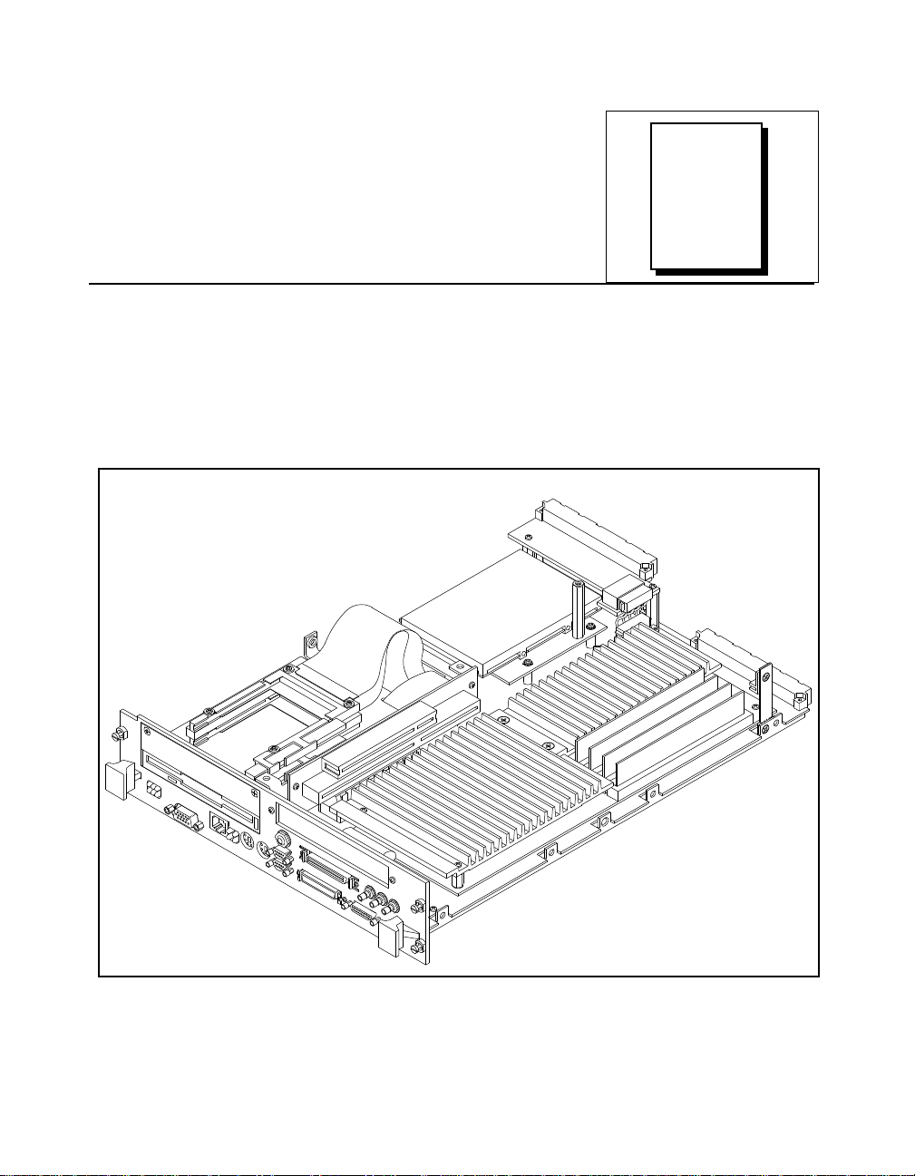
Figure 1-1 shows the VXIpc-850 with its cover removed.
Chapter
1
Figure 1-1. VXIpc-850 Embedded Computer
© National Instruments Corporation 1 -1 VXIpc-850 Series User Manual
Page 16

Chapter 1 Introduction
The VXIpc-850, a Pentium-based, C-size, embedded computer based
on the Peripheral Component Interface (PCI) bus, is a highperformance, easy-to-use platform for controlling VXIbus systems,
featuring complete VXI functionality through interactive utilities and
C function calls. In addition, the VXIpc-850 has an IEEE 488.2
interface that is compatible with the NI-488.2 architecture.
The VXIpc-850 is a custom computer that you install directly in two
C-size slots of your VXIbus mainframe. An embedded computer can
take full advantage of the VXI high-performance backplane capabilities
and give you direct control of VXI registers, memory, interrupts, and
triggers.
All models in the VXIpc-850 Series are fully VXIplug&play compliant
and are compatible with PC-compatible software tools, the National
Instruments LabVIEW and LabWindows®/CVI application software,
and the NI-VXI, NI-VISA, and NI-488.2 bus interface software.
Optional Equipment
You can contact National Instruments to order any of the following
optional equipment.
• COM1/2 adapter cable
• Enhanced parallel port adapter cable
• Single-shielded 2 m GPIB cable
• Upgrades for the VXIpc-850 modular CPU card
Optional Software
National Instruments has developed several software kits that you can
use with the VXIpc-850. The NI-VXI bus interface software for the
VXIpc-850 includes a Resource Manager, graphical and text-based
versions of an interactive VXI resource editor program, a
comprehensive library of software routines for VXI/VME
programming, and an interactive control program for interacting with
VXI/VME. You can use this software to seamlessly program multiplemainframe configurations and have software compatibility across a
variety of VXI/VME controller platforms.
The NI-488.2 software kit for the VXIpc-850 gives you accessibility to
the industry-standard NI-488.2 software for controlling external GPIB
instruments through the GPIB port on the front panel of your
VXIpc-850 Series User Manual 1 -2 © National Instruments Corporation
Page 17

Chapter 1 Introduction
VXIpc-850. The GPIB interface on the VXIpc-850 is fully compatible
with the NI-488.2 driver for a variety of operating systems. Any
software using NI-488.2 will run on the VXIpc-850.
You can also use the National Instruments LabVIEW and
LabWindows/CVI application programs and instrument drivers to ease
your programming task. These standardized programs match the
modular virtual instrument capability of VXI and can reduce your
VXI/VMEbus software development time. These programs are fully
VXIplug&play compliant and feature extensive libraries of VXI
instrument drivers written to take full advantage of direct VXI control.
LabVIEW is a complete programming environment that departs from
the sequential nature of traditional programming languages and features
a graphical programming environment.
LabWindows/CVI is an interactive C development environment for
building test and measurement and instrument control systems. It
includes interactive code-generation tools and a graphical editor for
building custom user interfaces.
LabVIEW and LabWindows/CVI include all the tools needed for
instrument control, data acquisition, analysis, and presentation. When
you order the LabVIEW VXI Development System for Windows or the
LabWindows/CVI VXI Development System for Windows, you also
get more than 500 complete instrument drivers, which are modular,
source-code programs that handle the communication with your
instrument to speed your application development.
Hardware Description
The VXIpc-850 Series controllers feature a modular, PCI-based local
bus design that makes it easy to use interchangeable daughterboards to
upgrade your controller to new microprocessors, without having to
replace the motherboard or enclosure. The VXIpc-850 Series currently
consists of three models, which vary in the speed of the Intel Pentium
microprocessor.
• The VXIpc-850/100 uses the 100 MHz version of the Intel
Pentium microprocessor.
• The VXIpc-850/133 uses the 133 MHz version of the Intel
Pentium microprocessor.
• The VXIpc-850/166 uses the 166 MHz version of the Intel
Pentium microprocessor.
© National Instruments Corporation 1 -3 VXIpc-850 Series User Manual
Page 18

Chapter 1 Introduction
The CPU module and its memory sockets are easily accessible for you
to install additional DRAM in the field—up to 128 MB. The
VXIpc-850 contains at least an 800 MB internal, enhanced IDE hard
disk. For information on adding RAM by installing SIMMs, refer to
Appendix A, Specifications.
Slot 0 Functionality
You can use the VXIpc-850 Series computers to achieve full VXI
Slot 0 control of your VXI system. You can also install the VXIpc-850
in another slot and use it in Non-Slot 0 mode. You do not have to
change any switches or jumpers when moving between these two
modes, as the VXIpc-850 can automatically detect whether it is
installed in Slot 0 and it will automatically enable or disable the Slot 0
onboard circuitry.
Custom Application-Specific Interface Chips
The VXIpc-850 Series uses the MITE, MANTIS, and TNT4882C
custom ASICs to deliver high VXI and GPIB performance, and can
achieve more than 20 MB/s DMA block-mode data transfer rates across
the VXI backplane.
The MITE custom ASIC is a sophisticated dual-channel DMA
controller with standard interfaces for VXI and PCI. By using MITE
DMA to transfer data and commands to and from devices, the MITE
frees the computer’s microprocessor to perform other tasks such as data
analysis and presentation. In addition to DMA, the MITE incorporates
the new VME64 MBLT (8-byte block transfers in which both the
address bus and data bus are used to transfer data) directly into the
ASIC to perform the fastest transfer operation to instruments. With the
multiple windowing scheme of the MITE, you can easily access all of
VXI address space.
The VXI trigger interface on the VXIpc-850 is based on the MANTIS
custom ASIC. By using the two SMB trigger I/O connectors on the
front panel, you can route any of the TTL trigger lines between the
backplane and external devices. The MANTIS provides the complete
VXI interface to the backplane connector in a single chip. The
VXIpc-850 can respond to all VXI-defined protocols on all P2 TTL and
ECL trigger lines at the same time. The MANTIS features an internal
cross-matrix switching system for routing between lines as well as to
and from the front panel and onboard clocks.
The VXIpc-850 uses the TNT4882C custom ASIC to give full GPIB
control of external instruments via a front-panel connector. GPIB
VXIpc-850 Series User Manual 1 -4 © National Instruments Corporation
Page 19

capability is fully compatible with IEEE 488.2 and the industrystandard NI-488.2 driver for a variety of operating systems.
Front Panel Features
The VXIpc-850 has the following front-panel features.
• Two PCMCIA slots (one Type I/II and one Type I/II/III)
• One full-size expansion slot that accepts either a PCI or a PC ISA
• Internal 3.5 in. floppy drive
• 13 front-panel connectors
• System reset push-button
• Six front-panel LEDs that show VXI and PC status
Chapter 1 Introduction
(XT-height) plug-in board
– RS-232 serial connector (two miniature)
– Extended capabilities parallel (ECP) connector
– VGA controller connector
– IEEE 488.2 connector
– 10BaseT Ethernet connector
– SCSI-2 connector
– External clock connector
– Trigger output connector
– Trigger input connector
– Audio output connector
– PS/2-style keyboard connector
– PS/2-style mouse connector
– SYSFAIL LED indicates that the VMEbus SYSFAIL line is
asserted.
– FAILED LED indicates that the VXIpc-850 is driving the
SYSFAIL signal.
– TEST LED indicates that the VXIpc-850 is performing its
self-tests or startup Resource Manager operations.
– ON LINE LED indicates that the VXIpc-850 is performing or
has completed its startup Resource Manager operations.
– ACCESS LED indicates when the VXIpc-850 MODID line is
asserted or the VXIbus registers or shared memory are
accessed by another bus master.
– DRIVE LED indicates when the internal hard drive is in use.
© National Instruments Corporation 1 -5 VXIpc-850 Series User Manual
Page 20

Chapter 1 Introduction
• Four front-panel LEDs that show Ethernet port status
Peripheral Expansion
The VXIpc-850 uses the PCI local bus for peripheral expansion. The
PCIbus is a 32-bit multimaster bus that achieves a top throughput of
132 MB/s and can handle numerous peripherals. The integrated PCI
local bus design of the VXIpc-850 gives you access to the following
peripherals:
• PCMCIA
• SCSI-2
• Super VGA
• Enhanced IDE for the hard drive
– RX LED indicates that the VXIpc-850 is receiving data
through its Ethernet port.
– TX LED indicates that the VXIpc-850 is transmitting data
through its Ethernet port.
– DSEL LED indicates that the Ethernet circuitry is being
accessed.
– LINK LED reflects Ethernet link status.
For information on installing and configuring these peripherals for use
with the VXIpc-850, refer to Chapter 5, Peripherals. You can also refer
to the VXIpc-850 Peripherals User Manual, which contains full
documentation for the video, PCMCIA, and SCSI peripherals.
VXIpc-850 Series User Manual 1 -6 © National Instruments Corporation
Page 21

Functional Overview
This chapter contains functional descriptions of each major logic block
on the VXIpc-850 Series embedded computer.
VXIpc-850 Functional Description
The VXIpc-850 is a modular PC in a dual-slot VXIbus C-size form
factor. It includes many high-performance peripherals that normally
require add-in cards on desktop PCs. In addition, it has a VXIbus
interface that is controlled from the PCI local bus, providing extremely
high performance and reliability.
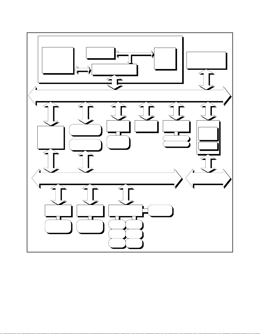
Figure 2-1 is a functional block diagram of the VXIpc-850. Following
the diagram is a description of each logic block shown.
Chapter
2
© National Instruments Corporation 2 -1 VXIpc-850 Series User Manual
Page 22
Chapter 2 Functional Overview
Memory
PCI-Based Pentium CPU Card
Cache
Chipset
32-bit, 5 V PCI Local Bus
CPU
Video
System I/O
Ethernet
RJ-45
Connector
PCI Expansion Slot
ISA Expansion Slot
GPIB
Miniature
Miniature
GPIB
Connector
Mouse
Reset
IDE
(Internal)
Floppy
ISA Bus
SCSI
SCSI
SCSI-2
SCSI-2
Connector
Connector
PC Peripherals
ECP
Parallel
Miniature
Serial (2)
Speaker
Keyboard
Figure 2-1. VXIpc-850 Block Diagram
PCMCIA
Type I/II/III Slot
Type I/II Slot
VXI
MITE
MANTIS
VXI Bus
VXIpc-850 Series User Manual 2 -2 © National Instruments Corporation
Page 23

Chapter 2 Functional Overview
The VXIpc-850 consists of the following logic blocks:
• CPU Card The modular architecture of the VXIpc-850 contains a plug-in CPU
card that can accommodate various Pentium- class processors. This
card includes the CPU, chipset support that connects the CPU
subsystem to the PCI bus, and the system cache and RAM.
• Video The video circuitry is a plug-in PCI card that has a 64-bit data path to
up to 4 MB of EDO DRAM.
• System I/O This block has the bridge between the PCI bus and the ISA bus. It
also has PCI bus arbitration logic and integrates PC-specific
hardware such as the DMA and interrupt controllers.
• PCI Expansion Slot This is a general-purpose PCI slot. It can accommodate any standard
5 V, 32-bit PCI card with a modified mounting bracket.
• ISA Expansion Slot This is a general-purpose ISA expansion slot. It can accommodate a
full-length XT-size card; however, the DRAM configuration may
mechanically interfere with a full-length card. Refer to Appendix E
for more information.
• SCSI The SCSI circuitry uses a PCI-SCSI bridge to provide a flexible
SCSI-2 connection on the front panel, usable for such devices as
external hard disks and CD-ROM drives.
• IDE This is a dedicated PCI-IDE chip providing fast ATA-2 transfers to
the internal hard drive.
• PCMCIA This is a dedicated PCI-PCMCIA interface that supports two
independent PCMCIA cards. One socket can accommodate a Type I,
II, or III card while the other accommodates a Type I or II card.
• VXI This is the PCI-VXIbus interface circuitry. The MITE is a National
Instruments ASIC developed to efficiently manage data transfers
between the VXIbus and the processor (via the PCI bus). The
MANTIS ASIC (also developed by National Instruments) performs
VXIbus arbitration and manages interrupts and triggers. Also part of
the VXIbus interface are the SMB connectors, which you can use to
route triggers and the CLK10 signal to or from the VXIbus.
• Ethernet This is an ISA-based Ethernet circuit that uses an RJ-45 connector for
access to an external Ethernet-based LAN.
• GPIB This logic block represents the IEEE 488.2 port on the VXIpc-850. It
uses the National Instruments TNT4882 ASIC for maximum
performance as an ISA-based GPIB controller.
• PC Peripherals These blocks represent the other peripherals supplied by the
VXIpc-850, including PS/2 mouse and keyboard ports, two miniature
serial ports, and ECP/EPP parallel port, speaker jack, reset button,
and a 1.44 MB, 3.5 in. floppy drive.
© National Instruments Corporation 2 -3 VXIpc-850 Series User Manual
Page 24
Chapter
Configuration and
Installation
This chapter contains the instructions to configure and install the
VXIpc-850 Series embedded computer. Unless otherwise noted, these
instructions apply to all models in the VXIpc-850 Series.
Warning: Electrostatic discharge can damage several components on your
VXIpc-850 module. To avoid such damage in handling the module,
touch the antistatic plastic package to a metal part of your VXI chassis
before removing the VXIpc-850 from the package.
Default Settings
This section summarizes the hardware default settings for the
VXIpc-850 for easy reference. The VXIpc-850 is set at the factory for
the most commonly used configuration.
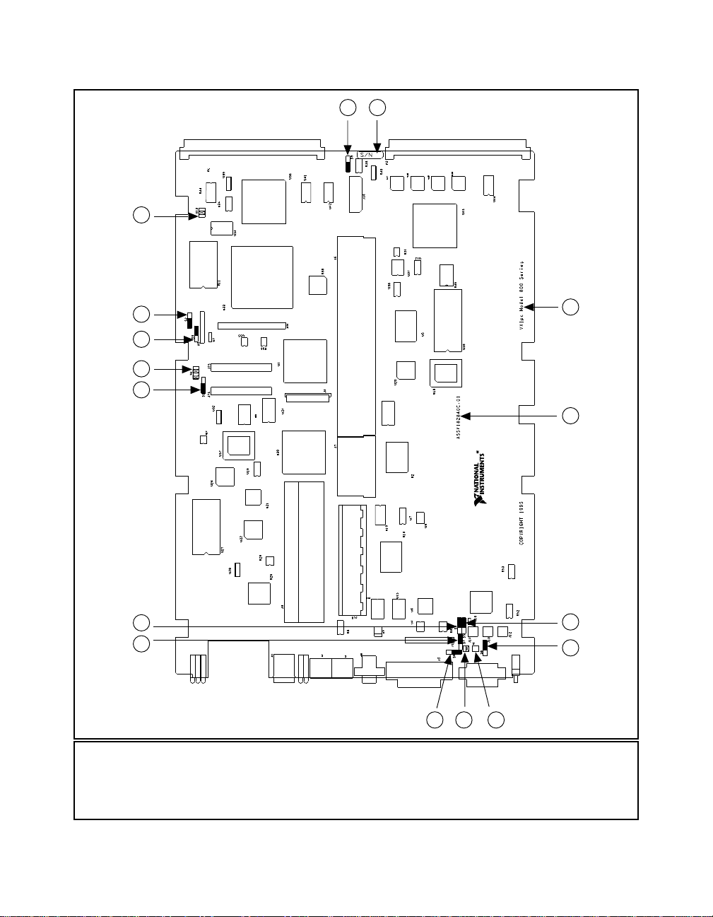
Figure 3-1 shows the location and factory-default settings of most of
the configuration switches and jumpers on the VXIpc-850.
3
© National Instruments Corporation 3 -1 VXIpc-850 Series User Manual
Page 25
Chapter 3 Configuration and Installation
7
8 9
6
5
4
3
2
1
10
11
12
13
141516
1 Trigger In Termination (S7) 7 Slot 0 Identification (W13) 13 GPIB IRQ Level (S8)
2 CLK10 Inversion (S4) 8 CLK10 Source (S3) 14 CMOS (W2)
3 Ethernet EEPROM Config. (S1) 9 Serial Number 15 SCSI Termination (W1)
4 LPT DMA Channel (W4) 10 Product Name 16 CLK10 Termination (S6)
5 MITE EEPROM Config. (S9) 11 Assembly Number
6 MITE Self Config. (S2) 12 CLK10 Direction (S5)
Figure 3-1. VXIpc-850 Parts Locator Diagram
VXIpc-850 Series User Manual 3 -2 © National Instruments Corporation
Page 26

Chapter 3 Configuration and Installation
Table 3-1 lists the factory-default settings and options for the onboard
jumpers and switches.
Table 3-1. VXIpc-850 Hardware Default Settings
Jumper/
Default Setting Optional Setting
Switch
W1 Supply SCSI
termination power
W2 Normal CMOS
Disable SCSI
termination
Clear CMOS
operation
W4 LPT1 uses DMA
Channel 1
W13 Enable automatic Slot 0
detection
S1 Enable Ethernet
EEPROM configuration
LPT uses DMA
Channel 3
Force Slot 0;
Force Non-Slot 0
Disable Ethernet
EEPROM configuration
(uses default power on
values)
S2 Enable MITE self-
configuration
S3 Source CLK10 from
onboard oscillator
S4 Non-inverted CLK10
Disable MITE selfconfiguration
Source CLK10 from
SMB
Inverted CLK10 output
output
S5 Receive CLK10 input
from SMB
S6 No termination on
CLK10 input
S7 No termination on
external trigger input
Source CLK10 output
to SMB
Terminate CLK10 input
to 50 Ω
Terminate external
trigger input to 50 Ω
S8 GPIB uses IRQ11 GPIB uses IRQ5
S9 MITE user
configuration
MITE factory
configuration
© National Instruments Corporation 3 -3 VXIpc-850 Series User Manual
Page 27

Chapter 3 Configuration and Installation
Configuring the VXIpc-850
This section describes how to configure the following options on the
VXIpc-850.
• VXIbus Slot 0/Non-Slot 0
• VXIbus CLK10 routing
• Trigger input termination
• EEPROM
• Installed system RAM
How to Remove the Metal Enclosure
The VXIpc-850 is housed in a metal enclosure to improve EMC
performance and to provide easy handling. You must remove this
enclosure to change many of the switch and jumper settings on the
VXIpc-850. You must also remove the enclosure to change the amount
of DRAM installed on the VXIpc-850.
To remove the metal enclosure, remove the five screws on the top, the
four screws on the bottom, and the three screws on the right side of the
enclosure.
VXIbus Slot 0/Non-Slot 0
The VXIpc-850 is configured at the factory to automatically detect if it
is installed in Slot 0 of a VXIbus mainframe. With automatic Slot 0
detection, you can install the VXIpc-850 into any VXIbus slot.
You can manually configure the VXIpc-850 for either Slot 0 or
Non-Slot 0 operation by defeating the automatic-detection circuitry.
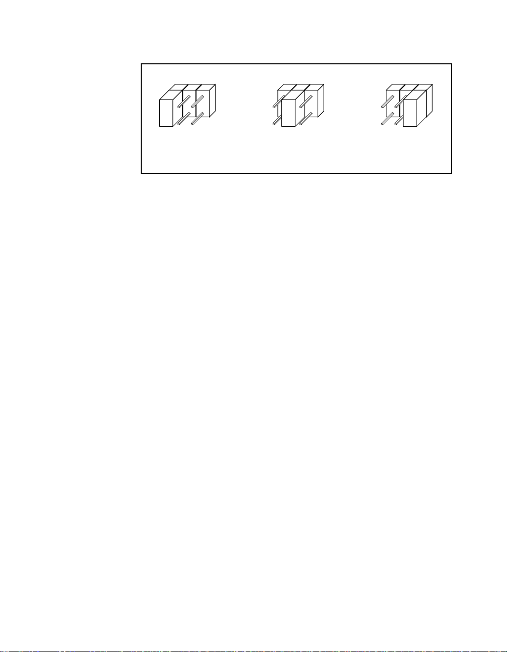
Use the three-position jumper W13 to select automatic Slot 0 detection,
Slot 0, or Non-Slot 0 operation. Figure 3-2 shows these three settings.
Warning: Do not install a device configured for Slot 0 into another slot without
first reconfiguring it to either Non-Slot 0 or automatic configuration.
Neglecting to do this could result in damage to the device, the VXIbus
backplane, or both.
VXIpc-850 Series User Manual 3 -4 © National Instruments Corporation
Page 28
Chapter 3 Configuration and Installation
a. Manual Non-Slot 0
Configuration
When the VXIpc-850 is installed in Slot 0, it becomes the VXIbus
System Controller. In this role, it has VXIbus Data Transfer Bus
Arbiter circuitry that accepts bus requests on all four VXIbus request
levels, prioritizes the requests, and grants the bus to the highest priority
requester. As VXIbus System Controller, the VXIpc-850 also drives the
16 MHz VXIbus system clock by an onboard 16 MHz oscillator.
As required by the VXIbus specification, the VXIpc-850 drives the
10 MHz signal CLK10 on a differential ECL output when installed in
Slot 0. When not installed in Slot 0, the VXIpc-850 only receives the
CLK10 signal.
VXIbus CLK10 Routing
When the VXIpc-850 is installed in Slot 0 of your mainframe, it
supplies the VXIbus CLK10 signal. The VXIpc-850 can use two
different sources to generate this signal: an onboard oscillator, or the
external CLK SMB connector. Use switch S3 to select these options, as
shown in Figure 3-3.
W13
W13
b. Automatic Slot 0
Detection (Default)
Figure 3-2. VXIbus Slot Configuration
W13
c. Manual Slot 0
Configuration
Notice that Figure 3-3b also shows switch S5. You must configure
these switches as shown when using the corresponding CLK10 source
setting of S3.
© National Instruments Corporation 3 -5 VXIpc-850 Series User Manual
Page 29
Chapter 3 Configuration and Installation
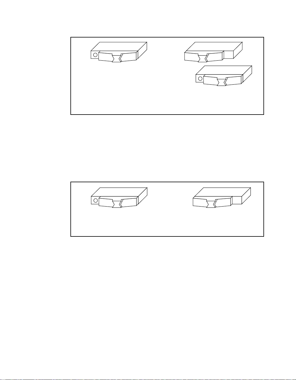
a. CLK10 Generated from Onboard
Oscillator (Default)
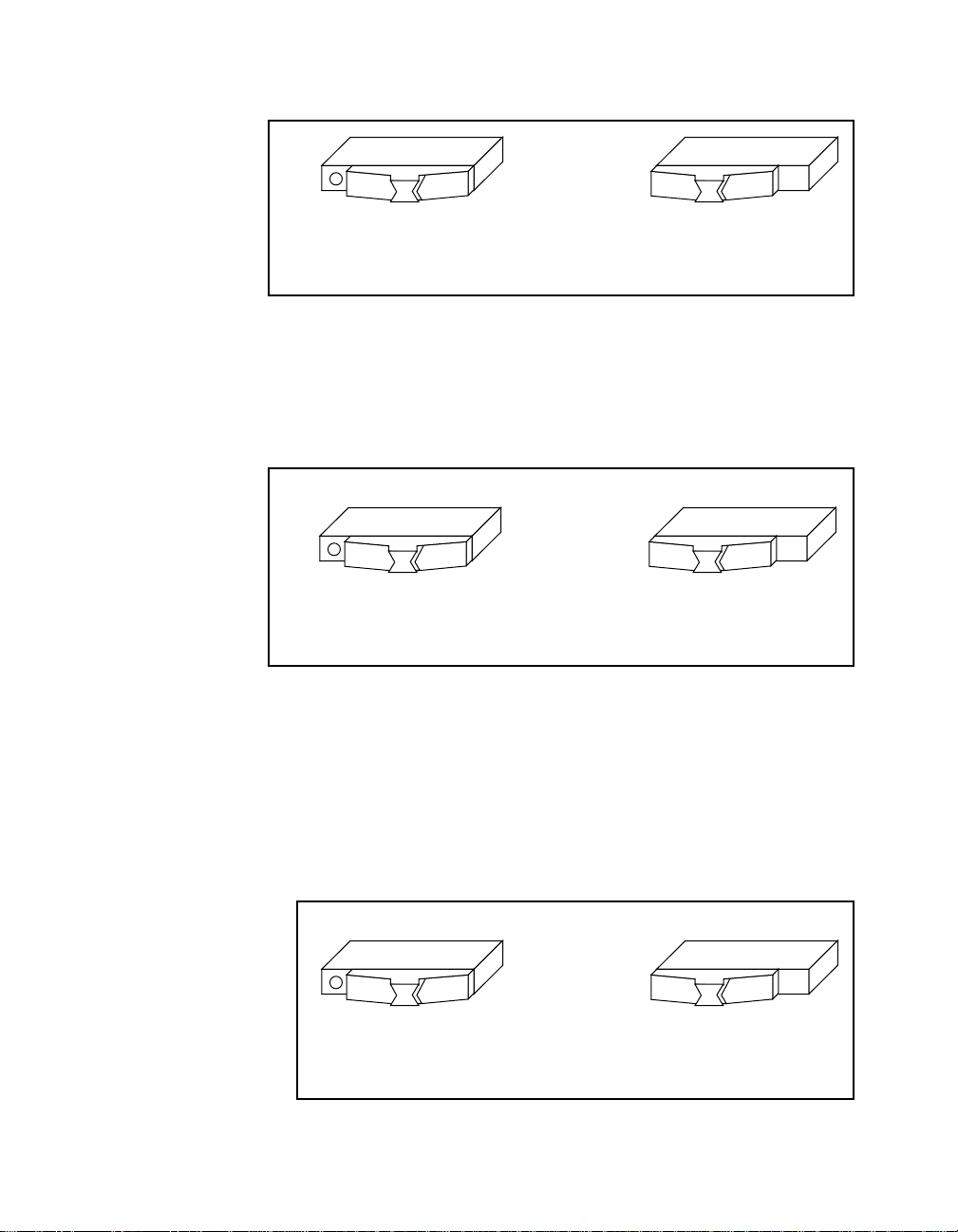
The VXIpc-850 can also be configured to drive the external CLK SMB
signal from the VXIbus CLK10 signal. Switch S5 controls whether the
VXIpc-850 drives or receives the external CLK SMB signal. If you
change the S5 setting to drive CLK10 out the external CLK10 SMB
connector (Figure 3-4b), do not set S3 to source CLK10 to the
backplane from the SMB; instead use the setting shown in Figure 3-3a.
S3 S3
S5
b. CLK10 Generated from SMB
Figure 3-3. VXIbus CLK10 Routing
S5S5
a. CLK10 SMB Receives 10 MHz
Signal (Default)
Figure 3-4. SMB CLK10 Direction
b. CLK10 SMB Drives 10 MHz
Signal from VXIbus CLK10
When switch S5 is set so that the VXIpc-850 receives the SMB CLK10
signal, you have the option to add a 50 Ω termination to the signal by
setting switch S6. Switch S6 is unused—its setting does not matter—
when S5 is configured to drive the external CLK SMB signal.
Figure 3-5 shows the settings for switch S6.
VXIpc-850 Series User Manual 3 -6 © National Instruments Corporation
Page 30
Chapter 3 Configuration and Installation
S6S6
a. Does Not Terminate CLK10
SMB Input (Default)
Figure 3-5. SMB CLK10 Termination
b. Terminates CLK10
SMB Input
You can use an additional switch, S4, to control the polarity of the
external CLK SMB signal when S5 is configured to drive it. S4 is
unused—its setting does not matter—when S5 is configured to receive
the external CLK SMB signal.
S4S4
a. Noninverted CLK10 Output
from SMB (Default)
Trigger Input Termination
You can use switch S7 to terminate the external trigger input SMB with
50 Ω to ground. Figure 3-7a shows the default setting for a nonterminated trigger input SMB. Use the setting of Figure 3-7b to
terminate the trigger input SMB. Switch S7 is located above switches
S4, S5, and S6, which have no effect on this configuration.
a. Does Not Terminate
Trigger Input (Default)
b. Inverted CLK10 Output
from SMB
Figure 3-6. SMB CLK10 Polarity
S7S7
b. Terminate Trigger
Input
Figure 3-7. SMB Trigger Input Termination
© National Instruments Corporation 3 -7 VXIpc-850 Series User Manual
Page 31

Chapter 3 Configuration and Installation
EEPROM
The VXIpc-850 has an onboard EEPROM, which stores default register
values for the VXI circuitry. These values are loaded when you power
up the computer. These values read from the EEPROM tell the PCI
interface of the VXIbus registers so that the VXI interface is ready to
respond to resource manager accesses within the required 5 s of
SYSRST* deasserting. You can disable this power-on selfconfiguration circuit using switch S2. Although this makes the VXI
circuitry unusable, it is sometimes helpful in debugging address and
interrupt conflicts with add-in boards. In general, however, you should
leave switch S2 in its factory-default setting. Figure 3-8 shows the
possible configurations for S2.
S2S2
a. VXI Circuitry Loads Power-on
Defaults from EEPROM (Default)
Figure 3-8. Power-On Self Configuration Status
b. Power-on Self Configuration
Circuit is Disabled
The EEPROM is divided into two halves; one half is factory configured
and one half is user configurable. Use switch S9 to control the
operation of the EEPROM. The setting of this switch determines
whether the VXIpc-850 boots off the factory-configured half or the
user-modified settings. This is useful in the event that the userconfigured half of the EEPROM becomes corrupted in such a way that
the VXIpc-850 boots to an unusable state. In its default setting, the
VXIpc-850 boots off the user-configurable half.
Figure 3-9 shows the configuration settings for EEPROM operation.
S9S9
a. Boot from User
Configuration (Default)
b. Boot from Protected
Configuration
Figure 3-9. SMB Trigger Input Termination
VXIpc-850 Series User Manual 3 -8 © National Instruments Corporation
Page 32

Chapter 3 Configuration and Installation
How to Fix an Invalid EEPROM Configuration
VXIEDIT is the software configuration utility in the NI-VXI software.
This utility is described in Chapter 3, NI-VXI Configuration Utility, in
the NI-VXI Software Manual for the VXIpc-850 Series. You can use
this utility to edit the configuration of the VXIpc-850. Some of these
settings are stored in files that are read by the NI-VXI software, while
other settings are stored directly in the VXIpc-850 EEPROM. Certain
EEPROM configurations can lock up your PCI computer while it is
booting up. Generally, only the size and location of the memory
windows can cause your VXIpc-850 to lock up your system. For
example, many PCI-based computers will not boot if a board in its
system requests more memory space than the computer can allocate. If
you encounter this situation you should reduce the size of the
VXIpc-850 user window.
If this situation occurs after you change the VXIpc-850 configuration,
perform the following steps to reconfigure the VXIpc-850.
1. Turn your computer off.
Warning: To protect both yourself and the mainframe from electrical hazards,
the mainframe should remain off until you are finished changing the
settings on the VXIpc-850 module.
2. Change switch S9 to the OFF position as shown in Figure 3-9b to
restore the factory configuration.
Installed System RAM
The 11 MB of installed RAM is factory configured per customer order.
You can change the amount of installed RAM on the VXIpc-850 by
installing DRAM SIMMs. Refer to Appendix A, Specifications, for
more information on SIMMs.
Configuring the PC
This section describes how to configure the following options on the
PC.
• SCSI termination
• GPIB interrupt level
• System CMOS
• Parallel port DMA level
• Ethernet power-on defaults
© National Instruments Corporation 3 -9 VXIpc-850 Series User Manual
Page 33

Chapter 3 Configuration and Installation
SCSI Termination
The VXIpc-850 uses active termination on the SCSI-2 bus. Because the
VXIpc-850 is always an end device, you should not need to disable the
termination; however, Figure 3-10 shows the settings for jumper W1.
GPIB Interrupt Level
a. GPIB Uses IRQ11 (Default) b. GPIB Uses IRQ5
W1
a. Terminate SCSI
Signals (Default)
Figure 3-10. SCSI Termination
You can program the GPIB interface on the VXIpc-850 to use one of
two ISA interrupts—5 or 11. Switch S8 controls which interrupt line
the GPIB interface uses. Figure 3-11 shows these settings.
Figure 3-11. GPIB Interrupt Level
W1
b. Do Not Terminate
SCSI Signals
S8S8
System CMOS
The VXIpc-850 contains a backed-up memory used to store BIOS
defaults and configuration information.
To clear the CMOS contents, simply short the pins of W2 as shown in
Figure 3-12b.
Warning: You should not keep these two pins shorted because the CMOS
memory cannot be sustained when the power is turned off if these two
pins are shorted.
VXIpc-850 Series User Manual 3 -10 © National Instruments Corporation
Page 34

Chapter 3 Configuration and Installation
W2 W2
Parallel Port DMA Level
You can use jumper W4 to configure the parallel port for either DMA
level 1 or DMA level 3. Refer to Figure 3-13 for the jumper settings.
a. Parallel Port Uses DMA
Ethernet Power-On Defaults
The VXIpc-850 Ethernet circuitry loads its power-on settings from an
EEPROM. Switch S1 should not be changed from its default setting;
however, the directions to do so are included here for informational
purposes. Figure 3-14 shows the settings.
a. Normal Operation
(Default)
Figure 3-12. System CMOS
W4 W4
Channel 1 (Default)
Figure 3-13. Parallel Port DMA Channel
b. Clear CMOS
Contents
b. Parallel Port Uses
DMA Channel 3
S1S1
a. Ethernet Power-On Defaults
b. Hardwired Ethernet Values
Loaded from EEPROM
Figure 3-14. Ethernet Power-On Defaults
© National Instruments Corporation 3 -11 VXIpc-850 Series User Manual
Page 35

Chapter 3 Configuration and Installation
Installing the VXIpc-850
This section contains general installation instructions for the
VXIpc-850. Consult your VXIbus mainframe user manual or technical
reference manual for specific instructions and warnings.
1. Plug in your mainframe before installing the VXIpc-850. The
power cord grounds the mainframe and protects it from electrical
damage while you are installing the module.
Warning: To protect both yourself and the mainframe from electrical hazards,
the mainframe should remain off until you are finished installing the
VXIpc-850 module.
2. Remove or open any doors or covers blocking access to the
mainframe slots.
3. If you are installing the VXIpc-850 into a D-size mainframe,
install a support designed for installing C-size boards in D-size
mainframes. The VXIpc-850 has no P3 connector and cannot
provide P3 Slot 0 control to VXI devices requiring this capability.
Warning: If the VXIpc-850 is not configured for automatic Slot 0 detection, be
certain that the slot you select in your VXIbus mainframe matches the
VXIpc-850 configuration as either a Slot 0 device or a Non-Slot 0
device. If you install your VXIpc-850 into a slot that does not
correspond with the jumper setting, you risk damage to the VXIpc-850,
the VXIbus backplane, or both.
4. Insert the VXIpc-850 in the slot you have selected by aligning the
top and bottom of the board with the card-edge guides inside the
mainframe. Slowly push the VXIpc-850 straight into the slot until
its plug connectors are resting on the backplane receptacle
connectors. Using slow, evenly distributed pressure, press the
VXIpc-850 straight in until it seats in the expansion slot. The front
panel of the VXIpc-850 should be even with the front panel of the
mainframe.
5. Tighten the retaining screws on the top and bottom edges of the
front panel.
6. Check the installation.
7. Connect the keyboard and mouse to the appropriate connectors.
Use the keyboard adapter cable that your received with your kit to
adapt AT-style keyboards to the VXIpc-850 mini-DIN connector.
8. Connect the VGA monitor video cable to the VGA connector.
VXIpc-850 Series User Manual 3 -12 © National Instruments Corporation
Page 36

Chapter 3 Configuration and Installation
9. Connect devices to ports as required by your system configuration.
Some ports, such as the COM ports, have adapter cables that you
can order from National Instruments.
10. Replace or close any doors or covers to the mainframe.
© National Instruments Corporation 3 -13 VXIpc-850 Series User Manual
Page 37

WinBIOS
This chapter contains information on WinBIOS, the low-level interface
between the hardware and PC software that configures and tests your
hardware at boot up. This BIOS (Basic Input Output System) provides
an easy-to-use graphical user interface to allow you to configure system
aspects according to your needs.
Entering WinBIOS Setup
To enter the WinBIOS setup program, perform the following steps.
1. Turn on or reboot the system. A screen appears with a series of
diagnostic checks.
2. When Hit <DEL> if you want to run SETUP appears,
press the <DEL> key to enter the BIOS setup program.
3. Choose options with the keyboard or mouse. Modify the settings to
reflect system options. Press <Alt-H> for Help.
Chapter
4
Using a Mouse with WinBIOS Setup
Point the cursor at the item you wish to modify and double-click the
left mouse button. When items appear, use the cursor to select values
and press the left mouse button to complete the changes. To leave the
current operation and return to the previous level, click on the exit box
in the window’s upper left corner.
© National Instruments Corporation 4 -1 VXIpc-850 Series User Manual
Page 38

Chapter 4 WinBIOS
Using the Keyboard with WinBIOS Setup
Although using the mouse is the easiest means to select BIOS options,
you can also use the keyboard. Table 4-1 lists the keys you use to
choose options:
Table 4-1. WinBIOS Options
Key Option
<TAB> Change current window
>, <, ^, v Move highlight to next field
<Ente r> Select highlighted option
+, - Increment or decrement a value
<ESC> Close the current operation and return to the
previous level (exits WinBIOS at the top level)
<PgUp> Return to previous page
<PgDn> Advance to next page
<Home> Return to the beginning of the text
<End> Advance to the end of the text
<Alt-H> Access a help window
<Alt-space> Exit WinBIOS setup
VXIpc-850 Series User Manual 4 -2 © National Instruments Corporation
Page 39

WinBIOS Main Menu
The WinBIOS main menu has four windows, each of which includes
several options. Table 4-2 lists descriptions for each of the main menu
windows.
Chapter 4 WinBIOS
Table 4-2. WinBIOS Main Menu Windows
Window Description
Setup Has five icons you can use to set system
configuration options such as time, date, hard
disk, floppy disk, and chip specific parameters.
Utility Has three icons you can use to detect hard drive
types and change screen colors.
Security Has two icons you can use to control password
and anti-virus settings
Default Has three icons you can use load original,
optimal, and fail-safe BIOS settings
For more detailed information, type <ALT+H> to access online help.
© National Instruments Corporation 4 -3 VXIpc-850 Series User Manual
Page 40

Peripherals
Chapter
5
This chapter contains brief descriptions of each of the peripheral
components of the VXIpc-850 Series embedded computer. Table 5-1
lists the VXIpc-850 peripheral components. Refer to the VXIpc-850
Peripherals User Manual for more complete information on each
peripheral.
Table 5-1. VXIpc-850 Peripheral Components
Peripheral External
Connector
Video 15-pin DSUB
(std VGA)
IDE None PCI Supports internal fast
Ethernet RJ-45 ISA 10BaseT Ethernet
PCMCIA Type I/II and
Type I/II/III
SCSI 36-pin SCSI-2 PCI External SCSI-2
GPIB 24-pin CHAMP ISA IEEE 488.2 interface
VXI Two 96-pin DIN
(rear of board)
Serial Port
Parallel Port
ISA- or
PCI-Based
PCI High-resolution/color
support for a SuperVGA
monitor
ATA-2 hard drive
connection
PCI Supports two independent
PCMCIA slots
connection for hard drives,
CD-ROM drives, and so on
compatible with the
National Instruments
AT-GPIB board
PCI
ISA
ISA
High-performance VXIbus
interface
16550 Serial ports
Extended capabilities
Function
© National Instruments Corporation 5 -1 VXIpc-850 Series User Manual
Page 41

Chapter 5 Peripherals
Software Installation
Your VXIpc-850 is one of the most complete PCs available on the
market, including desktop PCs. The VXIpc-850 includes video, IDE,
Ethernet, PCMCIA, SCSI, and GPIB, all of which require software
support to either enable them or maximize their performance. This
chapter contains information on how to install these drivers.
Why National Instruments Does Not Install All Peripheral Drivers
Although all drivers run concurrently with each other and can all run
together, each driver uses a certain amount of system resources.
Depending on the peripheral, these resources include DMA channels,
interrupts, or main memory. The latter is especially critical in a DOS
environment, where available memory can be as little as 400 KB with
all drivers loaded.
Because most VXIpc-850 users require some subset of the peripherals
offered, National Instruments allows the customer to determine where
system resources should be allocated, whether to peripherals, PCI or
ISA add-in boards, or applications.
Installing Peripheral Drivers
Find the c:\images directory in the root directory of your internal
hard drive. In it are subdirectories that contain images of the
installation diskettes for the peripheral drivers.
For most of the drivers, installation simply requires you to change to
the appropriate subdirectory (for example, change to
c:\images\enet for the Ethernet driver) and run the install or setup
progra m. Some dri vers do require extra steps, so read the installation
instructions before installing the driver.
For more information on SCSI, video, or PCMCIA, refer to the
VXIpc-850 Peripherals User Manual.
VXIpc-850 Series User Manual 5 -2 © National Instruments Corporation
Page 42

Video
Chapter 5 Peripherals
The VXIpc-850 uses the TGUI96XX Series Video Accelerator from
Trident Microsystems. For space and modularity reasons, National
Instruments designed a PCI-based video card using the TGUI96XX and
up to 4 MB of EDO DRAM. The performance of this card rivals that of
any other 64-bit graphics card on the market.
With 4 MB of DRAM, the TGUI96XX supports up to 1600x1200
resolution (65 KB colors maximum) or up to 16.7 million colors
(1280x1024 resolution maximum). You can also select the refresh rate
at which you would like the video circuitry to operate.
Caution: If you are using a Super VGA monitor, make sure it has a horizontal
scan rate of at least 50 kHz and a vertical scan rate of 60 Hz. Using the
Super VGA option with a monitor that does not meet these criteria will
damage your monitor.
You do not need to install the video drivers. The TGUI96XX driver
software comes installed on your hard disk with a default configuration
640x480 resolution at 16 colors and a 60 Hz refresh rate. This setting
was chosen to accommodate all VGA monitors; however, you may
want to increase the resolution, colors, and refresh rate according to the
capabilities of your monitor. Within Windows 3.1, in the Display
Driver and Utilities program group, you will find the TGUI96XX
utilities described in the Trident manual.
For archival purposes, an image of the TGUI96XX installation files are
provided in c:\images\video.
About the Trident Video Manual
In addition to the driver software, Trident Microsystems provides
documentation to its OEM customers. Refer to the VXIpc-850
Peripherals User Manual for more information.
Technical Information about the Video Interface
The TGUI96xx video accelerator has a 32-bit, 5 V PCI interface for
communication with the processor. It provides a dedicated 64-bit path
to the video memory. In the National Instruments implementation, it
interfaces to 70 ns EDO DRAM. There is 70 ns EDO DRAM instead of
© National Instruments Corporation 5 -3 VXIpc-850 Series User Manual
Page 43

Chapter 5 Peripherals
IDE
60 ns EDO DRAM because there was no measurable performance
increase.
The following provides information about the bootstrap settings on the
TGUI96XX and is for users already familiar with the TGUI96XX.
• Pulldown resistor on MD(4): Select PCI interface
• Pulldown resistor on MD(23): Enable DDC
• Pulldown resistor on MD(15): Provide eight CAS lines and
defining CAS0# as WE#
• Pulldown resistor on MD(7): Select EDO DRAM
• Pulldown resistor on MD(0): Memory Clock select 0
• No pulldown resistor on MD(1) nor MD(3): Select 70 ns memory
speed
The VXIpc-850 uses the CMD0640B PCI-IDE controller from CMD
Corporation. The chip supports two IDE ports although the VXIpc-850
only uses one IDE port. In order to take advantage of the advanced
features of the CMD0640B, install the QuickIDE driver as described in
the next section.
Installing the IDE Software
Perform the following steps to install the QuickIDE driver.
1. If you are running under DOS or Windows 3.x, an image of the
CMD QuickIDE software resides in c:\images\ide. (If you
are running Windows 95, the c:\images\ide directory will not
exist. Windows 95 includes a driver for the CMD0640B, so
separate installation is not necessary.) Under DOS or a DOS shell
under Windows, type c:\images\ide\install to install the
driver.
2. Once QuickIDE installation loads, you will be guided through the
installation process with a series of prompts and dialogs. If you
have a mouse, be sure to load your mouse driver first. If you do not
have a mouse, use the arrow keys to move within a field and use
the <TAB > key to move from one field to another. To select a
button or menu, hold down <ALT> while pressing the underlined
letter in the button or menu.
VXIpc-850 Series User Manual 5 -4 © National Instruments Corporation
Page 44

3. After you have answered all the questions, QuickIDE will copy
files to the c: drive and perform edits to files as needed. Backup
copies of any altered files will be created in case you want to undo
the installation. QuickIDE may modify CONFIG.SYS and/or
AUTOEXEC.BAT. The original files will be renamed
CONFIG.000, and so on.
Technical Information about the IDE Interface
In addition to the CMD part, two other devices provide IDE interfaces.
The Intel 82091AA Advanced Integrated Peripheral (AIP) provides
floppy, parallel, and serial support and has an IDE interface. The IDE
interface is disabled because the AIP is not a PCI-based part and
therefore provides a slower IDE interface than the CMD0640B. The
Intel 82092AA PPEC (described in the PCMCIA section) provides a
PCI-IDE interface; however, PCMCIA performance is restricted when
that interface is enabled. Disabling the IDE on the PPEC provides
maximum PCMCIA flexibility and performance.
The CMD0640B is configured so that the PCI base address registers are
enabled, setting the IDE port to Legacy Mode or Native Mode with
software. In Legacy Mode, the CMD0640B is compatible with standard
ISA IDE. The IDE registers are mapped to the standard ISA port
addresses and the IDE drive interrupt occurs at IRQ14. In PCI IDE
Native Mode, the CMD0640B task file registers may be mapped to
nonstandard port addresses and hard drive interrupts occur on a PCI
interrupt. On the VXIpc-850, the PCI interrupt used is INTD.
Chapter 5 Peripherals
The following describes the other options selected in the IDE circuitry
on the VXIpc-850.
• Chip ID Port Address Decoding is disabled
• Device ID Port Address is 0x178
• Device ID is 0x60 (the only option for a system with one
CMD0640B)
• Drive Address Register is disabled
The above options should not affect most users and are provided for
informational purposes to those already familiar with the CMD0640B.
PCI configuration utilities in the BIOS (and in Windows 95) will detect
the CMD0640B and program the necessary values.
© National Instruments Corporation 5 -5 VXIpc-850 Series User Manual
Page 45

Chapter 5 Peripherals
Ethernet
The VXIpc-850 uses the SMC 91C92 ISA-Ethernet controller from
Standard Microsystems Corporation as a 10BaseT node. The
VXIpc-850 provides four diagnostic LEDs that are activated by
transmit-and-receive activity, by link integrity status, and when the
91C92 register space is accessed.
The 91C92 supports IEEE 802.3 and you can reconfigure it without
changing jumpers. In addition, it does not require any memory space,
using 16 bytes of I/O space for all communication.
Configuring Your Ethernet Addresses
National Instruments programs the Ethernet address and other values
into a serial EEPROM from which the 91C92 loads its power-on
configuration. The defaults should be adequate for most situations;
however, using the ISMC9000 software, you can change the default
settings (except the Ethernet address) for the needs of your system.
Table 5-1. SMC 91C92 Default Settings
Settings
Ethernet Address 00:80:2F:01:xx:xx
I/O Base Address 0x300
ROM Base Address N/A
8/16 Bit Adapter 16-bit
Interface 10BASET
Interrupt Line IRQ9
Installing the Ethernet Software
Perform the following steps to install the Ethernet driver.
1. The ISMC9000 software resides in c:\images\enet. Under
DOS or a DOS shell under Windows, type
c:\images\enet\ismc9000 to run the configuration
program. If you do not want to change the default settings, you do
not need to run this program.
VXIpc-850 Series User Manual 5 -6 © National Instruments Corporation
Page 46

2. Once you exit the ISMC9000 program, the serial EEPROM is
updated and the values you selected are loaded into the 91C92 the
next time you boot the machine.
3. At this point, you need to install the appropriate network driver
unless you can use one of the network drivers included with the
operating system. For example, some operating systems may not
include TCP/IP.
If the driver you need is not supplied in the c:\images\enet
directory, you can either contact National Instruments for help on
finding the driver you need or, if you have internet access, you can
access the Microsoft WWW or FTP sites, which contain some
standard network drivers.
To install the network driver, follow the instructions in the
appropriate driver installation document.
Technical Information about the Ethernet Interface
The SMC 91C92 provides the designer with the ability to select
external or internal I/O decoding and the ability to select whether or not
it responds to 16-bit accesses. The 91C92 on the VXIpc-850 decodes
its own addresses (the ENDEC* pin is tied high) and is enabled for
16-bit accesses (EN16* is tied low).
Chapter 5 Peripherals
Support
You can contact SMC at the following numbers to obtain technical
support:
New York: (8:30 AM - 6:00 PM Eastern Time)
(800) 992-4762 from USA and Canada
(516) 435-6250
(516) 434-9314 (Fax)
California: (7:00 AM - 5:00 PM Pacific Time)
(800) NET-LEAD (638-5323) from USA and Canada
(714) 707-5607
(714) 707-2491 (Fax)
You can use the following BBS numbers to obtain the latest Ethernet
drivers from SMC:
Modem settings: 9600, 8, n, 1
California: (714) 707-2481
New York: (516) 434-3162
© National Instruments Corporation 5 -7 VXIpc-850 Series User Manual
Page 47

Chapter 5 Peripherals
PCMCIA
Germany: 49 (89) 928806-50
France: 33 (1) 39.73.57.00
United Kingdom: 44 (0) 932 350681
SMC also provides the drivers on their FTP site, which can be accessed
at ftp.smc.com or through their WWW site at www.smc.com.
Other drivers can be obtained from Microsoft at their WWW and FTP
sites: www.microsoft.com and ftp.microsoft.com.
The VXIpc-850 uses the 82092AA PCI to PCMCIA/Enhanced IDE
Controller (PPEC) from Intel for its PCMCIA interface, providing hot
swappable support for two PCMCIA devices.
The VXIpc-850 supports Type I, II, and III PCMCIA cards in its upper
slot and Type I and II PCMCIA cards in its lower slot. This allows you
to have a Type II and a Type III PCMCIA card in your system at the
same time.
Installing the PCMCIA Software
Perform the following steps to install the PCMCIA driver.
1. The software required for a PCMCIA interface, known as cardand-socket services, is provided by SystemSoft Corporation.
National Instruments includes CardWizard to users who order the
VXIpc-850 with DOS/Windows 3.1. CardWizard is a complete
package of card-and-socket services with built-in diagnostic
capabilities to help diagnose common PCMCIA problems.
CardWorks is a Windows 95 application that supplements the
PCMCIA support already in Windows 95. It also provides
diagnostic services.
2. An image of the SystemSoft CardWizard or CardWorks
installation disk is provided in c:\images\pcmcia. You run
SETUP from that directory. Because that directory is an image of
the installation disk, the setup utility actually creates a new
directory for its run-time files.
The VXIpc-850 Peripherals User Manual contains the complete
PCMCIA documentation.
VXIpc-850 Series User Manual 5 -8 © National Instruments Corporation
Page 48

Technical Information about the PCMCIA Interface
The PPEC chip has two modes. Mode 0 supports two independent
PCMCIA slots or one PCMCIA slot and two IDE interfaces (for four
drives). Mode 1 supports four non-independent PCMCIA slots and two
IDE interfaces.
Users who are already familiar with the Intel PPEC should note that the
VXIpc-850 uses Mode 0 (via pulldown resistors on
SPKROUT#/MODE and AREG#/IDECFG) to support hot insertion
and removal of the PCMCIA cards. This is not possible in Mode 1
because the PCMCIA slots in that mode share signals. The insertion
and removal of a card will disrupt communication with other cards in
the system. The IDE interface of the PPEC is disabled in favor of the
CMD0640B PCI-IDE chip described in this manual.
SCSI
The VXIpc-850 uses the NCR 53C810 PCI-SCSI controller from
Symbios Logic, Inc. (formerly NCR Corporation). The 53C810 is
based on a SCSI I/O processor core and incorporates a PCI bus master
DMA core.
Chapter 5 Peripherals
Installing the SCSI Software
To install the SCSI driver, locate an image of the NCR SDMS (SCSI
Device Management System) software, which resides in
C:\images\scsi. If you are running DOS or Windows 3.x, enter a
DOS shell and type C:\images\scsi\install to install the
driver. Refer to the SDMS software information in the VXIpc-850
Peripherals User Manual. Chapter 2 provides detailed installation
instructions for DOS and Windows 3.x. If you are running Windows
NT 3.5, you will need to add the SCSI driver in C:\images\scsi
under Windows NT Setup. Chapter 3 describes installing the SCSI
driver under Windows NT.
Technical Information about the SCSI Interface
The 53C810 supports the SCSI-2, 8-bit bus. It supports synchronous
transfer rates up to 10 MB/s, and asynchronous transfer rates up to
5 MB/s. It also includes a PCI bus master DMA device that is tightly
coupled to the SCSI core and supports uninterrupted scatter/gather
© National Instruments Corporation 5 -9 VXIpc-850 Series User Manual
Page 49

Chapter 5 Peripherals
memory operations. A 64-byte FIFO allows the 53C810 to support up
to 16 longword bursts across the PCI interface.
SCSI signals require termination at each end of the network. The
VXIpc-850 provides automatic termination networks (two TL2218
chips from Texas Instruments) that you can disable via a jumper
setting; however, you should not need to do this since the VXIpc-850
should be the controller (and therefore on the end) for any SCSI
network connected to it.
GPIB (IEEE 488.2)
The VXIpc-850 uses the National Instruments TNT4882C ASIC,
providing the VXIpc-850 with a full GPIB Talker/Listener/Controller
functionality. This ASIC gives the VXIpc-850 complete compatibility
with the National Instruments AT-GPIB/TNT. In fact, the default base
address, interrupt level, and DMA level are the same on the VXIpc-850
as they are on the AT-GPIB/TNT.
Because of this compatibility, included with your VXIpc-850 kit are the
same manuals usually sent with an AT-GPIB/TNT kit. They explain
how to get your GPIB system up and running.
Base Address, DMA, and IRQ Configuration
Although the VXIpc-850 hardware is compatible with the
AT-GPIB/TNT, you do not have the option to change the base address
or the DMA level of the GPIB circuitry on the VXIpc-850.
• The base I/O address is 2C0
• The DMA level is 5
• The IRQ is 11 (you can also select an IRQ of 5)
The hardware installation and configuration information in the GPIB
getting started manual is not relevant to the VXIpc-850.
Installing the NI-488.2 Software
Because the VXIpc-850 comes with the NI-488.2 software already
installed on it, you do not need to read the software installation chapter.
The rest of the GPIB getting started, user, and function reference
manuals contain information about how to configure and use your
GPIB system.
VXIpc-850 Series User Manual 5 -10 © National Instruments Corporation
Page 50

Specifications
This appendix describes the environmental, electrical, and mechanical
specifications of the VXIpc-850.
Electrical
Appendix
A
Current (A)
Voltage (V) Typical Maximum
+5 5.82 A 6.87 A
-5.2 224.5 mA 236 mA
-2 67.2 mA 95.2 mA
+12 2.26 mA 2.63 mA
-12 2.43 mA 2.43 mA
Physical
Characteristic Specification
Size Two-slot VXIbus C-Size Module
(233.35 by 340 by 60.96 mm)
Board Dimensions Fully Enclosed, Shielded VXI C-Size Board
233.35 by 340 mm
(9.187 by 13.386 in.)
Slot Requirements VXI C-Size Slot
Compatibility Fully Compatible with VXI Specification
VXI Keying Class Class 1 TTL
MTBF 22,098 hours
Weight 2.5 Kg (5.5 lb) Typical (16 MB DRAM Installed)
© National Instruments Corporation A-1 VXIpc-850 Series User Manual
Page 51

Appendix A Specifications
Environmental
Characteristic Specification
Temperature 0° to 55° C Operating;
-20° to 70° C Storage
Relative Humidity 0% to 95% Noncondensing, Operating;
0% to 95% Noncondensing, Storage
EMI FCC Class A Verified, EC Verified
Vibration Operational: 5 to 500 Hz, 0.31g, 3 axes
Non-operations: 5 to 500 Hz, 2.5g, 3 axes
Functional Shock MIL-T-28800E Class 3 (per Section 4.5.5.4.1)
Half-Sine Shock Pulse (11 ms duration, 30g peak, 3
shocks per face)
Note: Random vibration profiles were developed in accordance with
MIL-T-28800E and MIL-STD-810E Method 514. Test levels exceed those
recommended in MIL-STD-810E for Category 1 (Basic Transportation,
Figures 514.4-1 through 514.4-3). Test report available upon request.
Requirements
Characteristic Specification
VXIbus Configuration Space 64 B
A24 or A32 Space 16 KB Minimum (Programmable)
Performance
VME Transfer Rate
Peak D32 33 MB/s
Sustained D32 Reads 13.76 MB/s
Writes 11.37 MB/s
VXIpc-850 Series User Manual A-2 © National Instruments Corporation
Page 52

Appendix A Specifications
VMEbus Capability Codes
Capability Code Description
A32, A24, A16 (master) VMEbus master A32, A24, and A16 addressing
A32, A24, A16 (slave) VMEbus slave A32, A24, and A16 addressing
D64, D32, D16, D08(EO)
(master)
D64, D32, D16, D08(EO)
(slave)
BLT, MBLT (master) VMEbus master block and D64 transfers
BLT, MBLT (slave) VMEbus slave block and D64 transfers
RMW (master) VMEbus master read/modify/write transfers
RMW (slave) VMEbus slave read/modify/write transfers
RETRY (master) VMEbus master retry support
RETRY (slave) VMEbus slave retry support
FSD First slot detector
SCON VMEbus System Controller (Automatic Detection)
PRI, RRS Prioritized or Round Robin Select arbiter
ROR, FAIR Release on Request and FAIR bus requester
IH(7–1) Interrupt handler for levels 7–1
I(7–1) Interrupt requester for levels 7–1
D32, D16, D08(O)
(Interrupt Handler)
D32, D16, D08(O)
(Interrupter)
ROAK, RORA Release on Acknowledge or Register Access interrupter
BTO(x) VMEbus bus timer (programmable limit)
LOCK Can lock the VMEbus for indivisible transfers
VMEbus master D64, D32, D16, and D08 data sizes
VMEbus slave D64, D32, D16, and D08 data sizes
VMEbus D32, D16, D08(O) interrupt handler
VMEbus D32, D16, D08(O) interrupter
Adding RAM
To add RAM to the VXIpc-850, remove the top cover and add SIMM
modules to the two empty SIMM sockets. The maximum amount of
RAM that can be added to a standard configuration of 16 MB is
64 MB, yielding a total of 80 MB. By replacing the 16 MB SIMMs,
you can have a total of 128 MB.
© National Instruments Corporation A-3 VXIpc-850 Series User Manual
Page 53

Appendix A Specifications
National Instruments recommends the following types of SIMMs for
use with the VXIpc-850 controllers:
8 MB: 2 MB x 36 SIMMs - 70ns
16 MB: 4 MB x 36 SIMMs - 70ns
32 MB: 8 MB x 36 SIMMs - 70ns
The height of SIMMs used with VXIpc-850 controllers should be
0.85 in. or less. Contact National Instruments for recommendations on
specific manufacturers.
VXIpc-850 Series User Manual A-4 © National Instruments Corporation
Page 54

Appendix
VXIpc-850 System
Resources
This appendix describes what systems resources are available on the
VXIpc-850 and where they are allocated. Because PCI is a relatively
new addition to PCs, this chapter describes how PCI interrupts fit into a
PC architecture before listing the devices that use them.
PCI Interrupts
PCI interrupts can be shared by multiple devices and are therefore more
flexible than ISA interrupts. They do not actually connect to the
processor directly; they are instead mapped through ISA interrupts in
the system I/O module. The interrupt handler for a particular ISA
interrupt must know if it will be acknowledging a PCI device.
Resource Tables
This section provides tables describing where system resources are
assigned. Table B-1 lists how the ISA interrupts are allocated on the
VXIpc-850 and whether they are driven by a PCI interrupt. Table B-2
lists DMA channel allocation, and Table B-3 gives the I/O address
map.
B
Table B-1. ISA Interrupt Resource Allocations
ISA
Interrupt
NMI None Parity
0 None Timer
1 None Keyboard
© National Instruments Corporation B-1 VXIpc-850 Series User Manual
PCI
Interrupt Device
(continues)
Page 55

Appendix B VXIpc-850 System Resources
Table B-1. ISA Interrupt Resource Allocations (Continued)
ISA
Interrupt
PCI
Interrupt Device
2 None IRQ Expansion (8-15)
3 None COM2
4 None COM1
5 INTC,
INTB
GPIB/PCMCIA
Slot/Expansion
6 None Floppy Drive
7 None LPT1
8 None RTC
9 None Ethernet
10 INTA VXI, SCSI, PCMCIA
11 None GPIB/PCMCIA
Slot/Expansion
12 None Mouse
13 None FPERR
14 INTD IDE
15 None PCMCIA
Slot/Expansion
Table B-2. DMA Channel Resource Allocations
DMA
Channel Device
0 Free
1 Free
2 Floppy Drive
3 Free
4 Free
5 GPIB
6 Free
7 Free
VXIpc-850 Series User Manual B-2 © National Instruments Corporation
Page 56

Table B-3. I/O Address Map
Appendix B VXIpc-850 System Resources
I/O
Address Device
000-00F 8237 DMA #1 2E8-2EF COM*
020 -021 8259 PIC #1 2F8-2FF COM*
040-043 8253 Timer 300-30F Ethernet
060-066 8742 Controller 310-36F Free
070-077 CMOS RAM & NMI Mask Reg 370-377 Reserved
078-07B BIOS Timer 378-37F LPT*
080-090 DMA Page Registers 380-3B0 Free
092 Reserved 3BC-3BF LPT*
094-09F DMA Page Registers 3E8-3EF COM*
0A0-0A1 8259 PIC #2 3F0-3F7 Floppy
0B2-0B3 Advanced Power Management 3F8-3FF COM*
0C0-0DF 8237 DMA #2 (word mapped) 40A Scatter/Gather Int Status Reg
0F0-0FF Numeric Processor Error Reg 40B DMA1 Extended Mode Regs
170-177 Reserved 410-41F Scatter/Gather Status
I/O
Address Device
1F0-1F7 IDE 420-43F Scatter/Gather Descriptor Table
Pointer
200-270 Free 481-488 DMA High Page Regs
278-27F LPT* 4D0-4D1 Interrupt Edge/Level Control Regs
280-2DF Free 4D6 DMA2 Extended Mode Regs
2C0-2DF GPIB * Relocatable
Note: I/O locations in italics indicate addresses above 1 KB. These locations are
not usually accessible in an ISA-based system; however, newer PCI-based
chipsets have increased the amount of I/O space available.
© National Instruments Corporation B-3 VXIpc-850 Series User Manual
Page 57

LED Indicators
This appendix describes how to read the LEDs on the front panel to
interpret the status of the VXIpc-850.
VXIbus Interface Status LEDs
The VXIbus interface status LEDs are located at the top of the module
and include four LEDs: FAILED, SYSFAIL, ONLINE, and TEST.
They indicate the various stages of initialization that occur as the
VXIpc-850 boots. The following paragraphs describe each LED.
SYSFAIL LED
The SYSFAIL LED is lit when the VMEbus SYSFAIL signal is
asserted. It does not necessarily indicate that the VXIpc-850 is asserting
SYSFAIL, only that there is a device in the system asserting SYSFAIL.
Appendix
C
FAILED LED
The FAILED LED is lit when the VXIpc-850 is driving the SYSFAIL
signal. The VXIpc-850 asserts SYSFAIL when the PASSED bit in its
VXIbus status register is clear. The PASSED bit is set by the power-on
self configuration circuitry (POSC) when it has completed initializing
the VXIbus interface.
ONLINE LED
The ONLINE LED is lit when the Resource Manager has successfully
completed and the VXIbus interface is ready for application programs.
TEST LED
The TEST LED is lit when the power-on self configuration circuitry is
configuring the VXIbus interface.
© National Instruments Corporation C-1 VXIpc-850 Series User Manual
Page 58

Appendix C LED Indicators
LEDs and System Startup Cycle
Table C-1 shows a system startup cycle and possible points of failure,
up to and including the state in which VXIinit asserts the ONLINE
LED.
Table C-1. LEDs and System Startup Status
Step LEDs Lit Status Possible Problem if VXIpc-850 Fails
1 None Machine just turned on. The VXIpc-850 is not receiving power.
2 FAILED,
SYSFAIL
3 FAILED,
TEST
4 TEST POSC circuitry has initialized
5 None POSC cycles are complete.
6 ONLINE Resman has been executed,
Now asserting SYSFAIL
because VXIbus interface has
not been initialized yet.
VXI interface is being
initialized by MITE power-on
self configuration (POSC)
circuitry.
VXI interface, setting PASSED
and DONE bits.
VXI port is ready to respond to
Resource Manager inquiries.
indicating that the VXI
software can now communicate
with the VXI circuitry.
Power-on self configuration (POSC)
cannot execute because of problems
with system reset or because the
POSCEN switch is incorrectly
configured.
POSC has stalled.
POSC stalled before clearing the TEST
LED.
POSC completed successfully;
however, Resman either hung or was
not executed.
Resman interface initialized
successfully.
If either the SYSFAIL or FAILED LED remains lit, perform the
following steps:
1. Power off the mainframe.
2. Remove all other modules from the mainframe.
3. Make sure that the VXIpc-850 jumper settings are correct.
4. Make sure that the VXIpc-850 is seated properly in the mainframe.
5. Power on the mainframe and observe whether the SYSFAIL and
FAILED LEDs become unlit some time before the operating
system boots.
VXIpc-850 Series User Manual C-2 © National Instruments Corporation
Page 59

Board Access LEDs
The board access LEDs, ACCESS and DRIVE, indicate when board
resources have been accessed. The following paragraphs describe these
LEDs.
ACCESS LED
When lit, the ACCESS LED indicates that the VXIpc-850 MODID line
is asserted or that another VXIbus master is accessing VXIbus shared
registers or shared memory.
DRIVE LED
The DRIVE LED light indicates that an access to the internal hard disk
drive is occurring.
Ethernet LEDs
The Ethernet LEDs (RX, TX, LINK, and DSEL) indicate the status of
the Ethernet interface.
Appendix C LED Indicators
RX LED
The RX LED lights when the Ethernet interface is receiving a packet.
TX LED
The TX LED lights when the Ethernet interface is transmitting a
packet.
LINK LED
The LINK LED indicates LINK status and can generally be used to
check if Ethernet activity is occurring.
DSEL LED
The DSEL (Device Select) LED lights when Ethernet registers are
being accessed.
© National Instruments Corporation C-3 VXIpc-850 Series User Manual
Page 60

Front Panel and Connectors
This appendix describes the front panel and connectors on the
VXIpc-850. This material contains the information relevant to
VXIplug&play Specification VPP-8, VXI Module/Mainframe to
Receiver Interconnection.
Note: The illustrations in this appendix show the mating face of the connectors.
An asterisk suffix (*) on a signal name indicates that the signal is active low.
Front Panel
Figure D-1 shows the front panel layout of the VXIpc-850. The
drawing shows dimensions relevant to key elements on the front panel.
Dimensions are shown in millimeters and inches. The front panel
thickness is 2.49 mm (0.098 in.).
Appendix
D
© National Instruments Corporation D-1 VXIpc-850 Series User Manual
Page 61

Appendix D Front Panel and Connectors
FAILED
ONLINE
DRIVE
DSEL
SYSF
TEST
ACC
TX
RX
LNK
1
2
G
P
I
B
RESET
VXIpc-850
TRG
IN
TRG
OUT
CLK
TM
Figure D-1. VXIpc-850 Front Panel Layout and Dimensions
Keyboard and Mouse
Figure D-2 shows the location and pinouts for the keyboard and mouse
connectors on the VXIpc-850. Table D-1 gives the name and
description for the keyboard and mouse connector signals.
Amp manufactures a mating connector with part numbers 212437-4
(housing), 212435-7 (ferrule), and 66735-4 (pin contact).
VXIpc-850 Series User Manual D-2 © National Instruments Corporation
Page 62

Appendix D Front Panel and Connectors
4
6
2
1
1
2
Figure D-2. Keyboard and Mouse Connectors Location and Pinout
Table D-1. Keyboard and Mouse Connector Signals
2
1
Keyboard
5
3
4
6
Mouse
5
3
Signal
Pin
Name Signal Description
1 DATA Data
2 NC Not Connected
3 GND Ground
4 +5 V +5 volts
5 CLK Clock
6 NC Not Connected
VGA
Figure D-3 shows the location and pinouts for the VGA connector on
the VXIpc-850. Table D-2 gives the name and description for the VGA
connector signals.
Amp manufactures a mating connector with part numbers 748364-1
(housing) and 748333-2 (pin contact).
© National Instruments Corporation D-3 VXIpc-850 Series User Manual
Page 63

Appendix D Front Panel and Connectors
51015
VGA
1
11
6
1
2
Figure D-3. VGA Connector Location and Pinout
Table D-2. VGA Connector Signals
Pin Signal
Signal Description
Name
1 R Red
2 G Green
3 B Blue
4 NC Not Connected
5 GND Ground
6 GND Ground
7 GND Ground
8 GND Ground
9 +5 VDC +5 Volts
10 GND Ground
11 NC Not Connected
12 SD Serial Data
13 HSync Horizontal Sync
14 VSync Vertical Sync
15 SC Serial Clock
VXIpc-850 Series User Manual D-4 © National Instruments Corporation
Page 64

Ethernet
Appendix D Front Panel and Connectors
Figure D-4 shows the location and pinouts for the Ethernet connector
on the VXIpc-850. Table D-3 gives the name and description for the
Ethernet connector signals.
Amp manufactures a mating connector, part number 554739-1.
1
Ethernet
1
2
Figure D-4. Ethernet Connector Location and Pinout
Table D-3. Ethernet Connector Signals
8
Pin Signal Description
1 Differential Transmit
2 Differential Transmit
3 Differential Receive
4NC
5NC
6 Differential Receive
7NC
8NC
© National Instruments Corporation D-5 VXIpc-850 Series User Manual
Page 65

Appendix D Front Panel and Connectors
COM1 and COM2
Figure D-5 shows the location and pinouts for the COM1 and COM2
connectors on the VXIpc-850. Table D-4 gives the name and
description for the COM1 and COM2 connector signals.
ITT Cannon manufactures a serial port mating connector, part number
MDSM-9SC-Z11.
1596
COM1
1
2
1596
COM2
Figure D-5. COM1 and COM2 Connectors Location and Pinout
Table D-4. COM1 and COM2 Connector Signals
Signal
Pin
Name Signal Description
1 DCD* Data Carrier Detect
2 RXD* Receive Data
3 TXD* Transmit Data
4 DTR* Data Terminal Ready
5 GND Ground
6 DSR* Data Set Ready
7 RTS* Ready to Send
8 CTS* Clear to Send
9 RI* Ring Indicator
VXIpc-850 Series User Manual D-6 © National Instruments Corporation
Page 66

Parallel Port
Appendix D Front Panel and Connectors
Figure D-6 shows the location and pinouts for the IEEE-1284
connector on the VXIpc-850. Table D-5 gives the name and description
for the IEEE-1284 connector signals.
Amp manufactures a parallel port compatible connector, part number
2-175677-5.
SYSF
FAILED
TEST
ONLINE
ACC
DRIVE
1
2
36
18
Parallel Port
19
1
Figure D-6. Parallel Port Connector Location and Pinout
© National Instruments Corporation D-7 VXIpc-850 Series User Manual
Page 67

Appendix D Front Panel and Connectors
Table D-5. Parallel Port Connector Signals
Signal
Pin
1 BUSY* Device Busy 19 GND Ground
2 SLCTIN* Select Input 20 GND Ground
3 ACK* Acknowledge 21 GND Ground
4 FAULT* Fault 22 GND Ground
5 ERROR Error 23 GND Ground
6 PD0 Data Bit 0 24 GND Ground
7 PD1 Data Bit 1 25 GND Ground
8 PD2 Data Bit 2 26 GND Ground
9 PD3 Data Bit 3 27 GND Ground
10 PD4 Data Bit 4 28 GND Ground
11 PD5 Data Bit 5 29 GND Ground
12 PD6 Data Bit 6 30 GND Ground
13 PD7 Data Bit 7 31 GND Ground
14 INIT* Initialize Printer 32 GND Ground
15 STROBE* Strobe 33 GND Ground
16 SLCT Select 34 GND Ground
17 AUTOFD Auto Line Feed 35 GND Ground
18 +5V +5 Volts 36 NC Not Connected
Name
Signal
Description Pin
Signal
Name
Signal
Description
SCSI
Figure D-7 shows the location and pinouts for the SCSI connector on
the VXIpc-850. Table D-6 gives the name and description for the SCSI
connector signals.
Amp manufactures a SCSI compatible connector, part number
749111-4.
VXIpc-850 Series User Manual D-8 © National Instruments Corporation
Page 68

Appendix D Front Panel and Connectors
1
2
Figure D-7. SCSI Connector Location and Pinout (SCSI II)
Table D-6. SCSI Connector Signals
36
19
Pin Signal
18
SCSI
1
Signal Description
Name
1–11, 15–25,
GND Ground
35–36, 40, 42
12–14, 37–39 NC Not Connected
26 D0 Data 0
27 D1 Data 1
28 D2 Data 2
29 D3 Data 3
30 D4 Data 4
31 D5 Data 5
32 D6 Data 6
33 D7 Data 7
34 DP Parity
38 TERMPWR Termination Power
41 ATN* Attention
43 BUSY* Busy
44 ACK* Acknowledge
45 RESET* Reset
(continues)
© National Instruments Corporation D-9 VXIpc-850 Series User Manual
Page 69

Appendix D Front Panel and Connectors
GPIB (IEEE-488.2)
Figure D-8 shows the location and pinouts for the GPIB connector on
the VXIpc-850. Table D-7 gives the name and description for the GPIB
connector signals.
ITT Cannon manufactures a GPIB mating connector, part number
MDSM-255C-Z11.
Table D-6. SCSI Connector Signals (Continued)
Pin Signal Name Signal Description
46 MSG* Message
47 SEL* Select
48 CMD_DATA Command/Data
49 REQ* Request
50 IN_OUT In/Out
1
2
14
25
Figure D-8. GPIB Connector Location and Pinout
VXIpc-850 Series User Manual D-10 © National Instruments Corporation
1
GPIB
13
Page 70

Appendix D Front Panel and Connectors
Table D-7. GPIB Connector Signals
Pin Signal Name Signal Description
1 DIO1* Data Bit 1
2 DIO2* Data Bit 2
3 DIO3* Data Bit 3
4 DIO4* Data Bit 4
5 EOI* End or Identify
6 DAV* Data Valid
7 NRFD* Not Ready for Data
8 NDAC* Not Data Accepted
9 IFC* Interface Clear
10 SRQ* Service Request
11 ATN* Attention
12 SHIELD Chassis ground
13 DIO5* Data Bit 5
14 DIO6* Data Bit 6
15 DIO7* Data Bit 7
16 DIO8* Data Bit 8
17 REN* Remote Enable
18 GND Logic Ground
19 GND Logic Ground
20 GND Logic Ground
21 GND Logic Ground
22 GND Logic Ground
23 GND Logic Ground
24 GND Logic Ground
25 GND Logic Ground
External SMBs
Figure D-9 shows the location and pinouts for the SMB connector on
the VXIpc-850. Table D-8 gives the name and description for the SMB
connector signals.
Amp manufactures an SMB mating connector, part number
1-413985-0.
© National Instruments Corporation D-11 VXIpc-850 Series User Manual
Page 71

Appendix D Front Panel and Connectors
1
2
Center
Shield
Figure D-9. SMB Connectors Location and Pinout
Table D-8. SMB Connector Signals
Pin Signal Description
Center TTL Trigger or Clock Signal
Shield Ground
VXIbus P1 and P2
Figure D-10 shows the location and pinouts for the VXIbus connector
on the VXIpc-850. Table D-9 gives the name and description for the
VXIbus P2 connector signals. Table D-10 gives the name and
description for the VXIbus P1 connector signals.
C32
B32
A32
P1 ConnectorP2 Connector
Figure D-10. VXIbus Connectors Location and Pinout
VXIpc-850 Series User Manual D-12 © National Instruments Corporation
C1
B1
A1
Page 72

Appendix D Front Panel and Connectors
Table D-9. VXIbus P2 Connector Signals Table D-10. VXIbus P1 Connector Signals
Pin Row C Row B Row A Pin Row C Row B Row A
1 CLK10+ +5 V ECLTRG0 1 D08 BBSY* D0 0
2 CLK10- GND -2 V 2 D09 BCLR* D01
3 GND Not
Connected
4 -5.2 V A24 GN D 4 D11 BG0IN* D03
5 Not Connected A25 MODID12 5 D12 BG0OUT* D04
6 Not Connected A26 MODID11 6 D13 BG1IN* D05
7 GN D A27 -5.2 V 7 D14 BG1OUT* D06
8 Not Connected A28 MODID10 8 D15 BG2IN* D07
9 Not Connected A29 MODID09 9 GN D BG2OUT* GN D
10 GND A3 0 GND 10 SYSFAIL* BG3IN* SYSCLK
11 Not Connected A31 MODID08 11 BERR* BG3OUT* GND
12 Not Connected GND MODID07 12 SYSRESET* BR0* DS1*
13 -2 V +5 V -5.2 V 13 LWORD* BR1* DS0*
14 Not Connected D16 MODID06 14 AM5 BR2* WRITE*
15 Not Connected D17 MODID05 15 A23 BR3* GND
16 GND D18 GN D 16 A22 AM0 DTACK*
17 Not Connected D19 MODID04 17 A21 AM1 GND
18 Not Connected D20 MODID03 18 A20 AM2 AS*
19 -5.2 V D21 -5.2 V 19 A19 AM3 GND
20 Not Connected D22 MODID02 20 A18 GND IACK*
21 Not Connected D23 MODID01 21 A17 Not
22 GND GND GND 22 A16 Not
23 TTLTRG1* D24 TTLTRG0* 23 A15 GND A M4
24 TTLTRG3* D25 TTLTRG2* 24 A14 IRQ7* A07
25 GND D26 +5 V 25 A13 IRQ6* A06
26 TTLTRG5* D27 TTLTRG4* 26 A12 IRQ5 A05
27 TTLTRG7* D28 TTLTRG6* 27 A11 IRQ4 A04
28 GND D29 GND 28 A10 IRQ3 A03
29 Not Connected D30 Not Connected 29 A09 IRQ2 A02
30 GND D31 MODID00 30 A08 IRQ1 A01
31 Not Connected GND GND 31 +12 V Not
32 Not Connected +5 V Not Connected 32 +5 V +5 V +5 V
ECLTRG1 3 D10 ACFAIL* D02
IACKIN*
Connected
IACKOUT*
Connected
-12 V
Connected
© National Instruments Corporation D-13 VXIpc-850 Series User Manual
Page 73

Appendix D Front Panel and Connectors
Speaker
Figure D-11 shows the location of the speaker connection on the
VXIpc-850.
Switchcraft manufactures a mating speaker connector, part
number 750.
1
2
Figure D-11. Speaker Connection Location
Speaker
VXIpc-850 Series User Manual D-14 © National Instruments Corporation
Page 74

Signal Characteristics
Refer to the relevant standard for the signal characteristics for VGA,
SCSI, Ethernet, keyboard, mouse, parallel, serial, and GPIB.
Table D-11 shows the signal characteristics for the SMB and speaker
connections.
Table D-11. Signal Characteristics for SMB and Speaker Connections
Appendix D Front Panel and Connectors
Voltage
Signal
SMB (TRIG out, CLK out) 0 to 3.4 V 200 mA DC-10 MHz
Speaker 0 to 4.3 V 75 mA DC-20 kHz
SMB (TRIG in) 0 to 5 V 100 mA* DC-10 MHz
* with 50 Ω termination
Range
Maximum
Current
Frequency
Range
© National Instruments Corporation D-15 VXIpc-850 Series User Manual
Page 75

Appendix
Modifying and Installing
I/O Expansion Boards
This appendix explains how to modify and install an I/O board in the
VXIpc-850.
Height of VXIpc-850 Plug-In Boards
In general, the VXIpc-850 can accommodate any standard-size PCI
card and any XT-height ISA card. The height of an I/O card is
measured from the bottom of the bus connector to the top of the board,
as shown in Figure E-1.
E
Height
(4.2 in. max)
(7.65 in. max recommended)
Figure E- 1. I/O Board Dimensions for VXIpc-850 Expansion Slot
Both PC height ISA cards and PCI cards are 4.2 in. high. The
VXIpc-850 does not support PC-AT height ISA cards, which are 4.8 in.
high.
© National Instruments Corporation E-1 VXIpc-850 Series User Manual
Length
Page 76

Appendix E Modifying and Installing I/O Expansion Boards
Length of VXIpc-850 Plug-In Boards
The VXIpc-850 will easily accommodate any PCI or ISA I/O boards
that are 4.2 in. high or less and are 7.72 in. in length or less. If you want
to install a longer board, you must consider several conditions such as
handling, vibration, and possible contact with the system DRAM
SIMMs.
When you install a plug-in board, the front end of the board that sticks
out of the VXIpc-850 front panel is firmly supported, because it is
screwed to the front panel of the VXIpc-850. Longer boards cannot be
firmly supported away from the front panel; therefore, if your system
requires rugged handling or resides in a high vibration environment,
plug-in boards longer than 7.72 in. are not recommended.
The restrictions on the length of a VXIpc-850 plug-in board also
depend on the possibility of physical contact with the system DRAM
SIMMs. Because the DRAM SIMMs are more likely to interfere with
ISA cards than PCI cards, the two are discussed separately in the
following sections.
Length of PCI Plug-In Boards
The VXIpc-850 should accommodate any standard 32-bit, 5 V PCI I/O
board. The maximum standard dimensions of a PCI I/O board are
12.283 in. by 4.2 in. PCI cards are installed in the VXIpc-850 such that
the board components face the processor card, which contains the
processor and system RAM. Exceptionally tall PCI components on a
plug-in board may physically contact the DRAM SIMMs installed on
the CPU card of the VXIpc-850, as shown in Figure E-2.
PCI CardRiser Card
Heat SinkFront Panel
Figure E- 2. Component Height Restrictions on PCI Plug-In Boards
VXIpc-850 Series User Manual E-2 © National Instruments Corporation
Support Brackets
.62 in. max to Heat Sink.32 in. max to SIMMs
SIMMs
VXI Connector
Page 77

Because larger DRAM sizes may employ taller SIMMs, you must be
careful that the component height of the PCI board does not interfere
with the SIMMs in such a way that electrical shorts occur or that the
PCI board is stressed enough to compromise its physical or electrical
integrity.
Length of ISA Plug-In Boards
Because ISA boards mount with the components facing away from the
CPU card, which contains the processor and system RAM, tall DRAM
SIMMs will interfere with the circuit card of the plug-in board. Most
SIMM modules are at least one inch in height and would extend into
the plane of the ISA circuit card by 0.15 in. Therefore, National
Instruments does not recommend the use of cards that are greater than
7.72 in. in length. They can be made to fit; however, care must be taken
to ensure the following conditions:
• Contact of the board with the SIMMs should not cause electrical
shorts (because of through-hole component leads on the side of the
plug in board that contacts the SIMMs).
• Contact of the board with the SIMMs does not cause physical
stress to the plug-in board.
• Contact of the board with the SIMMs does not cause physical
stress to the riser board into which the plug in board is inserted.
Appendix E Modifying and Installing I/O Expansion Boards
Figure E-3 shows the length restrictions on ISA cards for the
VXIpc-850.
Riser Card
7.72 in. max
Front Panel
© National Instruments Corporation E-3 VXIpc-850 Series User Manual
Heat Sink
Figure E- 3. Length Restrictions on ISA Plug-In Boards
ISA Board
Support Brackets
SIMMs
VXI Connector
Page 78

Appendix E Modifying and Installing I/O Expansion Boards
Installing an I/O Board
Materials Needed
You need the following pieces to install an expansion board in the
VXIpc-850.
• User-defined panel is required on the expansion boards based on
National Instruments blank PCI or ISA panels. Contact National
Instruments for a list of specifications for user-defined panels.
As an alternative, you can modify the blank panels provided with
the VXIpc-850. Custom panel design services are available from
National Instruments for a nominal fee.
• PEM nut or a 4-40 nut with lock washer (hole diameter should be
0.125 in).
• 4-40 x 1/4 in. stainless steel panhead screw.
Installation Steps
Follow these steps to install the expansion board.
1. Notice that the VXIpc-850 includes two card guides that can be
rotated to secure the top of either a PCI or an ISA plug-in board.
You may use one or both of these card guides, depending on the
length of your installed board. Loosen the screw holding the guide
and rotate the guide to the uppermost position for PCI boards or
the lowermost position for ISA boards.
2. Replace the manufacturer-supplied panel bracket with the custom
bracket. The two holes in the bracket align with existing holes in
the VXIpc-850 front panel.
3. Seat the board firmly in one of the expansion bus connectors.
4. Affix the board to the front panel with the two screws. You can use
a PEM nut on the back (far) side of the bracket, or a 4-40 nut with
lock washer (hole diameter should be 0.125 in.). In either case, use
a 4-40 x 1/4 in. stainless steel panhead screw to mount the
board/bracket assembly to the front panel.
VXIpc-850 Series User Manual E-4 © National Instruments Corporation
Page 79

Appendix E Modifying and Installing I/O Expansion Boards
Figure E-4 shows a PCI board installed in the VXIpc-850.
a. PCI Board Installed b. ISA Board Installed
Figure E- 4. PCI Board Installed in a VXIpc-850
© National Instruments Corporation E-5 VXIpc-850 Series User Manual
Page 80

Common Questions
This appendix answers common questions you may have when using
the VXIpc-850.
What do the LEDs on the front of the VXIpc-850 mean?
Refer to Appendix C, LED Indicators, for a description of the front
panel LEDs.
Is something wrong with the VXIpc-850 if the red SYSFAIL and FAILED LEDs
stay lit after booting the VXIpc-850?
If either the SYSFAIL or FAILED LED remains lit, refer to
Appendix C, LED Indicators, for troubleshooting steps.
Can I access 32-bit registers in my VXIbus system from the VXIpc-850?
Appendix
F
Yes. The VXIpc-850 uses the 32-bit PCI bus to interface to the
VXIbus. In fact, the VXIbus circuitry on the VXIpc-850 also supports
the new VME64 standard for D64 accesses. Refer to your VXI
software manual for more information.
What kind of signal is CLK10 and what kind of signal do I need for an external
CLK10?
CLK10 is a differential ECL signal on the backplane. However, the
oscillator for the VXIpc-850 and the EXTCLK input from the front
panel use TTL levels; therefore, you need to supply a TTL-level signal
for EXTCLK. Our voltage converters convert the signal to differential
ECL.
What is the accuracy of the CLK10 signal?
The CLK10 signal generated by the VXIpc-850 is ±100 ppm (0.01%)
as per the VXIbus specification. If you need a more accurate CLK10
signal, you can use the EXTCLK input at the front of the VXIpc-850.
© National Instruments Corporation F-1 VXIpc-850 Series User Manual
Page 81

Appendix F Common Questions
If I boot the computer without video, and then plug in the video, why is it in black
and white?
I’ve installed the SCSI software. Why doesn’t the VXIpc-850 recognize my SCSI
device?
What type of video interface is onboard the VXIpc-850? What video drivers are
included with the VXIpc-850? Can I use Super VGA with my VXIpc-850? If my
application requires a special type of video display, how do I configure my
VXIpc 850?
When the computer first boots, the video chips try to synchronize with
the monitor. If the monitor is not there, the video chips cannot
synchronize and establish color. You need to have the monitor attached
at boot time to get color.
This problem usually occurs when SCSI has not been enabled in the
BIOS. Enter your BIOS by pressing <DEL> at boot time. In the Setup
window, click on the Chipset icon. Select the On Board PCI SCSI
option and enable it.
The VXIpc-850 uses the Trident Microsystems TGUI96xx chip family,
a combination graphics accelerator and RAMDAC. The TGUI9660 is
the first chip from this family used. Succeeding pin-compatible chips
will follow. The chips in this family are compatible with the Standard
VGA video output MS Windows video driver, as well as the Trident
Microsystems video driver. For information on the Trident driver, refer
to the VXIpc-850 Peripherals User Manual.
If your application requires a special type of video display, you can
remove the PCI video card included with your VXIpc-850. Contact
National Instruments for information on how to do this.
What kind of monitor can I use with the VXIpc-850?
VXIpc-850 computers that use Super VGA video output will work only
with monitors having a horizontal scan rate of at least 50 kHz and a
vertical scan rate of 60 Hz.
Warning: Make sure that your monitor meets this specification. Enabling the Super
VGA option on a monitor that does not meet this specification will cause
damage to your monitor.
VXIpc-850 Series User Manual F-2 © National Instruments Corporation
Page 82

Appendix F Common Questions
What if my keyboard connector does not fit into the keyboard port on the
VXIpc-850?
You can plug keyboards that have a 6-pin Mini DIN PS/2 type
connector directly into the VXIpc-850. You can use the keyboard
adapter cable that is included with every VXIpc-850 kit to adapt the
larger AT keyboard connector to the 6-pin Mini DIN connector.
How do I connect an external speaker to the VXIpc-850 to get audio capability?
A twisted-pair cable connects the front panel audio connector to the
VXIpc-850 motherboard. Connect the external speaker to this
front-panel connector. The center pin of the connector provides the
audio signal. The shield of the connector is GROUND.
How do I add RAM to the VXIpc-850? What is the maximum amount of RAM that
I can have on the VXIpc-850?
For information about adding RAM to the VXIpc-850, refer to
Appendix A, Specifications.
Which interrupt levels are free to be used by ISA bus boards? Which area of upper
memory (adapter space) is free for use by ISA bus boards or expanded memory
manager software programs?
See Appendix B, VXIpc-850 System Resources, for information on the
available port I/O register space, upper memory area, interrupts, and
DMA channels.
How do I install the VXIpc-850 in a slot other than Slot 0?
The VXIpc-850 automatically detects whether or not it is in Slot 0 of a
VXIbus mainframe. You do not need to change jumper settings to
install the VXIpc-850 in a slot other than Slot 0 unless you have
defeated the first slot detector (FSD) circuitry by changing jumper
W13.
Refer to Chapter 3 of this manual, Configuration and Installation, for
information on enabling and defeating the FSD circuitry.
How do I check the configuration of the memory, floppy drive, hard drive,
time/date, and so on?
You can view these parameters in the BIOS setup. To enter the BIOS
setup, reboot the VXIpc-850 and press the < DEL > key during the
memory tests. Refer to Chapter 4, WinBIOS, for more information.
© National Instruments Corporation F-3 VXIpc-850 Series User Manual
Page 83

Appendix F Common Questions
How do I disable the automatic memory check when booting the VXIpc-850?
Can I upgrade my VXIpc-850?
What should I do if I cannot boot from the hard disk?
Why does my computer hang on CSALLOC when I install the PCMCIA Card
Wizard?
How can I boot from an external SCSI hard drive?
Though the BIOS will always check memory below 1 MB, you can
disable it from checking for memory above 1 MB. To change the
BIOS, enter the setup by pressing <DEL> as the system is booting and
select the Advanced icon in the Setup window. Disable the Above 1 M
Memory Test, save your settings, and reboot the system.
You can upgrade the modular CPU card to upgrade the processor.
Contact National Instruments for information.
Make sure the IDE block is set to Auto, LBA is enabled, and 32-bit
disk access is disabled.
CSALLOC hangs unless the serial ports are set to 3E8 and 2E8.
In the Setup/Standard window change the Master drive setting from
User to SCSI, and make sure the SCSI is enabled in the Setup/Chipset
window.
Can I use the internal IDE drive and an external SCSI hard drive at the same time?
Yes, but you can only boot from the internal IDE drive in this
configuration.
My CMOS is corrupted. How do I set it back to default?
1. Select Default/Optimal.
2. Make sure floppy A is set to 1.44 in the Setup/Standard.
3. In the Setup/Advanced enable AutoBlock IDE, enable LBA mode,
and disable 32-bit disk access.
4. In Setup/Peripheral change the programming mode to manual,
enable FDC, set Serial Port 1 to 3E8, and set Serial Port 2 to 2E8.
5. Run Utility/Detect Master to find the hard disk.
VXIpc-850 Series User Manual F-4 © National Instruments Corporation
Page 84

Appendix
G
Customer Communication
For your convenience, this appendix contains forms to help you gather the information necessary
to help us solve technical problems you might have as well as a form you can use to comment on
the product documentation. Filling out a copy of the Technical Support Form before contacting
National Instruments helps us help you better and faster.
National Instruments provides comprehensive technical assistance around the world. In the U.S.
and Canada, applications engineers are available Monday through Friday from 8:00 a.m. to
6:00 p.m. (central time). In other countries, contact the nearest branch office. You may fax
questions to us at any time.
Electronic Services
Bulletin Board Support
National Instruments has BBS and FTP sites dedicated for 24-hour support with a collection of
files and documents to answer most common customer questions. From these sites, you can also
download the latest instrument drivers, updates, and example programs. For recorded instructions
on how to use the bulletin board and FTP services and for BBS automated information, call
(512) 795-6990. You can access these services at:
United States: (512) 794-5422 or (800) 327-3077
Up to 14,400 baud, 8 data bits, 1 stop bit, no parity
United Kingdom: 01635 551422
Up to 9,600 baud, 8 data bits, 1 stop bit, no parity
France: 1 48 65 15 59
Up to 9,600 baud, 8 data bits, 1 stop bit, no parity
FTP Support
To access our FTP site, log on to our Internet host, ftp.natinst.com, as anonymous and use
your Internet address, such as joesmith@anywhere.com, as your password. The support files
and documents are located in the /support directories.
© National Instruments Corporation G-1 VXIpc-850 Series User Manual
Page 85

FaxBack Support
FaxBack is a 24-hour information retrieval system containing a library of documents on a wide
range of technical information. You can access FaxBack from a touch-tone telephone at the
following numbers: (512) 418-1111 or (800) 329-7177
E-Mail Support (currently U.S. only)
You can submit technical support questions to the appropriate applications engineering team
through e-mail at the Internet addresses listed below. Remember to include your name, address,
and phone number so we can contact you with solutions and suggestions.
GPIB: gpib.support@natinst.com
DAQ: daq.support@natinst.com
VXI: vxi.support@natinst.com
LabVIEW: lv.support@natinst.com
LabWindows: lw.support@natinst.com
HiQ: hiq.support@natinst.com
VISA: visa.support@natinst.com
Fax and Telephone Support
National Instruments has branch offices all over the world. Use the list below to find the technical
support number for your country. If there is no National Instruments office in your country,
contact the source from which you purchased your software to obtain support.
Telephone Fax
Australia 03 9 879 9422 03 9 879 9179
Austria 0662 45 79 90 0 0662 45 79 90 19
Belgium 02 757 00 20 02 757 03 11
Canada (Ontario) 519 622 9310
Canada (Quebec) 514 694 8521 514 694 4399
Denmark 45 76 26 00 45 76 26 02
Finland 90 527 2321 90 502 2930
France 1 48 14 24 24 1 48 14 24 14
Germany 089 741 31 30 089 714 60 35
Hong Kong 2645 3186 2686 8505
Italy 02 413091 02 41309215
Japan 03 5472 2970 03 5472 2977
Korea 02 596 7456 02 596 7455
Mexico 95 800 010 0793 5 520 3282
Netherlands 0348 433466 0348 430673
Norway 32 84 84 00 32 84 86 00
Singapore 2265886 2265887
Spain 91 640 0085 91 640 0533
Sweden 08 730 49 70 08 730 43 70
Switzerland 056 200 51 51 056 200 51 55
Taiwan 02 377 1200 02 737 4644
U.K. 01635 523545 01635 523154
Page 86

Technical Support Form
Photocopy this form and update it each time you make changes to your software or hardware, and
use the completed copy of this form as a reference for your current configuration. Completing this
form accurately before contacting National Instruments for technical support helps our
applications engineers answer your questions more efficiently.
If you are using any National Instruments hardware or software products related to this problem,
include the configuration forms from their user manuals. Include additional pages if necessary.
Name
Company
Address
Fax ( ) Phone ( )
Computer brand Model Processor
Operating system (include version number)
Clock Speed MHz RAM MB Display adapter
Mouse yes no Other adapters installed
Hard disk capacity MB Brand
Instruments used
National Instruments hardware product model Revision
Configuration
National Instruments software product Version
Configuration
The problem is
List any error messages
The following steps will reproduce the problem
Page 87

Hardware and Software Configuration Form
Record the settings and revisions of your hardware and software on the line to the right of each
item. Complete a new copy of this form each time you revise your software or hardware
configuration, and use this form as a reference for your current configuration. Completing this
form accurately before contacting National Instruments for technical support helps our
applications engineers answer your questions more efficiently.
National Instruments Products
VXIpc-850 Hardware Settings
VXIpc-850 Part Number __________________________________________________________
VXIpc-850 Serial Number ________________________________________________________
Processor Speed _________________________________________________________________
DRAM SIMMs Installed __________________________________________________________
Hard Drive Size __________________________ Video Memory _________________________
Slot Location ___________________________________________________________________
W1 Setting: SCSI Termination _____________________________________________________
W2 Setting: CMOS ______________________________________________________________
W4 Setting: LPT1 DMA __________________________________________________________
W13 Setting: Slot 0 Detection ______________________________________________________
S1 Setting: Ethernet EEPROM _____________________________________________________
S2 Setting: MITE Self-Configuration ________________________________________________
S3 Setting: CLK10 Source ________________________________________________________
S4 Setting: Inverted/Non-inverted CLK10 Output ______________________________________
S5 Setting: CLK10 SMB __________________________________________________________
S6 Setting: CLK10 Input Termination _______________________________________________
S7 Setting: External Trigger Input Termination ________________________________________
S8 Setting: GPIB IRQ Level _______________________________________________________
S9 Setting: MITE User/Factory Configuration _________________________________________
Page 88

NI-VXI Software Settings
NI-VXI Software Version Number __________________________________________________
Using VXIedit or VXItedit?________________________________________________________
Logical Address _________________________________________________________________
Device Type ___________________________________________________________________
Address Space __________________________________________________________________
VXI Shared RAM Size ___________________________________________________________
Shared RAM Pool (Windows) _____________________________________________________
Byte Order for Lower Half Window _________________________________________________
Byte Order for Upper Half Window _________________________________________________
Mapping Scheme for Lower and Upper Half Windows of VXI Shared RAM _________________
______________________________________________________________________________
Resource Manager Delay _________________________________________________________
Number of Handlers _____________________________________________________________
Number of Interrupters ___________________________________________________________
Servant Area Size _______________________________________________________________
Protocol Register ________________________________________________________________
Read Protocol Response __________________________________________________________
System IRQ Level _______________________________________________________________
VXI Bus Timeout _______________________________________________________________
Arbiter Type ___________________________________________________________________
Arbiter Timeout _________________________________________________________________
Fair Request ____________________________________________________________________
Request Level __________________________________________________________________
A24/A32 Slave Write Post ________________________________________________________
VXI Retry Protocol ______________________________________________________________
Page 89

VXI Slave Auto Retry ____________________________________________________________
VXI Transfer Limit ______________________________________________________________
User Window Base ______________________________________________________________
User Window Size _______________________________________________________________
User Window Below 1 MB ________________________________________________________
Driver Window Base _____________________________________________________________
Driver Window Size _____________________________________________________________
Driver Window Below 1 MB ______________________________________________________
Other Products
Mainframe Make and Model _______________________________________________________
Microprocessor _________________________________________________________________
Clock Frequency ________________________________________________________________
Type of Video Board Installed _____________________________________________________
Operating System _______________________________________________________________
Operating System Version ________________________________________________________
Operating System Mode __________________________________________________________
Programming Language __________________________________________________________
Programming Language Version ___________________________________________________
Other Boards in System ___________________________________________________________
Monitor (Manufacturer, Model) ____________________________________________________
Mouse (Manufacturer, Model) _____________________________________________________
Keyboard (Manufacturer, Model) ___________________________________________________
Other Peripherals (Manufacturer, Model) _____________________________________________
______________________________________________________________________________
______________________________________________________________________________
______________________________________________________________________________
______________________________________________________________________________
Page 90

Documentation Comment Form
National Instruments encourages you to comment on the documentation supplied with our
products. This information helps us provide quality products to meet your needs.
Title: VXIpc™-850 Series User Manual
Edition Date: April 1996
Part Number: 321124A-01
Please comment on the completeness, clarity, and organization of the manual.
If you find errors in the manual, please record the page numbers and describe the errors.
Thank you for your help.
Name
Title
Company
Address
Phone ( )
Mail to: Technical Publications Fax to: Technical Publications
National Instruments Corporation National Instruments Corporation
6504 Bridge Point Parkway (512) 794-5678
Austin, TX 78730-5039
Page 91

Glossary
Prefix Meaning Value
Glossary
n- nanoµ- micro-
m- milli-
k- kilo-
M mega-
G- giga-
10
10
10
10
10
10
-9
-6
-3
3
6
9
A
A Amperes
address Character code that identifies a specific location (or series of
locations) in memory
address space A set of 2n memory locations differentiated from other such sets
in VXI/VMEbus systems by six addressing lines known as
address modifiers. n is the number of address lines required to
uniquely specify a byte location in a given space. Valid numbers
for n are 16, 24, and 32. In VME/VXI, because there are six
address modifiers, there are 64 possible address spaces.
ANSI American National Standards Institute
© National Instruments Corporation Glossary-1 VXIpc-850 Series User Manual
Page 92

Glossary
B
b bits
B bytes
backplane An assembly, typically a printed circuit board, with 96-pin
connectors and signal paths that bus the connector pins. A C-size
VXIbus system will have two sets of bused connectors called J1
and J2. A D-size VXIbus system will have three sets of bused
connectors called J1, J2, and J3.
BIOS Basic Input/Output System. BIOS functions are the fundamental
level of any PC or compatible computer. BIOS functions
embody the basic operations needed for successful use of the
computer’s hardware resources.
C
CLK10 A 10 MHz, ± 100 ppm, individually buffered (to each module
slot), differential ECL system clock that is sourced from Slot 0
of a VXIbus mainframe and distributed to Slots 1 through 12
on P2. It is distributed to each slot as a single-source, singledestination signal with a matched delay of under 8 ns.
CMOS Complementary Metal Oxide Semiconductor; a process used in
making chips
D
DIN Deutsches Institut für Normung—German Standards Institute
DMA Direct Memory Access; a method by which data is transferred
between devices and internal memory without intervention of
the central processing unit
DRAM Dynamic RAM (Random Access Memory); storage that the
computer must refresh at frequent intervals
VXIpc-850 Series User Manual Glossary-2 © National Instruments Corporation
Page 93

Glossary
E
ECL Emitter-Coupled Logic
EDO Extended Data Out; a DRAM architecture that shortens overall
access latency, improving performance
EEPROM Electronically Erasable Programmable Read Only Memory
embedded controller An intelligent CPU (controller) interface plugged directly into
the VXI backplane, giving it direct access to the VXIbus. It must
have all of its required VXI interface capabilities built in.
EMC Electromagnetic Compliance
F
fair requester A VXIbus device that will not arbitrate for the VXIbus after
releasing it until it detects the bus request signal inactive. This
ensures that all requesting devices will be granted use of the bus.
FPERR Floating Point Error
G
GPIB General Purpose Interface Bus (IEEE 488)
H
hex hexadecimal; the numbering system with base 16, using the
digits 0 to 9 and letters A to F
Hz hertz; cycles per second
I
IDE Integrated Drive Electronics. Denotes the most common
interface to the hard drive on PCs.
IEEE Institute of Electrical and Electronics Engineers
© National Instruments Corporation Glossary-3 VXIpc-850 Series User Manual
Page 94

Glossary
in. inches
I/O input/output; the techniques, media, and devices used to achieve
communication between machines and users
INT interrupt
INTA PCI interrupt A
INTB PCI interrupt B
INTC PCI interrupt C
INTD PCI interrupt D
interrupt A means for a device to request service from another device
interrupt handler A VMEbus functional module that detects interrupt requests
generated by interrupters and responds to those requests by
requesting status and identify information
interrupt level The relative priority at which a device can interrupt
IRQ* Interrupt signal
ISA Industry Standard Architecture denotes a common expansion bus
used in PCs
K
KB kilobytes of memory
L
LED Light-emitting diode
M
m meters
master A functional part of a VME/VXIbus device that initiates data
transfers on the backplane. A transfer can be either a read or a
write.
VXIpc-850 Series User Manual Glossary-4 © National Instruments Corporation
Page 95

Glossary
MB megabytes of memory
MITE A National Instruments custom ASIC, a sophisticated dual-
channel DMA controller that incorporates the Synchronous MXI
and VME64 protocols to achieve high-performance block
transfer rates
MODID Module ID Lines. Used in VXI to geographically locate boards
and to dynamically configure boards
MTBF Mean Time Between Failure
N
NI-VXI The National Instruments bus interface software for
VME/VXIbus systems
NMI NonMaskable Interrupt
Non-Slot 0 device A device configured for installation in any slot in a VXIbus
mainframe other than Slot 0. Installing such a device into Slot 0
can damage the device, the VXIbus backplane, or both.
P
PCI Peripheral Component Interconnect. The PCI bus is a high-
performance 32-bit or 64-bit bus with multiplexed address and
data lines.
PCMCIA Personal Computer Memory Card International Association
PEM Penn Engineering Manufacturing Corporation. A manufacturer
of nuts pressed into metal
POSC Power-On Self Configuration. A process by which the MITE
chip programs its own registers from EEPROMs at power up
PWB Printed Wire Board
© National Instruments Corporation Glossary-5 VXIpc-850 Series User Manual
Page 96

Glossary
R
Resource Manager A message-based Commander located at Logical Address 0,
which provides configuration management services such as
address map configuration, Commander and Servant mappings,
and self-test and diagnostic management
S
s seconds
SCSI Small Computer System Interface
SIMM Single In-line Memory Module
slave A functional part of a VME/VXIbus device that detects data
transfer cycles initiated by a VMEbus master and responds to the
transfers when the address specifies one of the device’s registers
Slot 0 device A device configured for installation in Slot 0 of a VXIbus
mainframe. This device is unique in the VXIbus system in that it
performs the VMEbus System Controller functions, including
clock sourcing and arbitration for data transfers across the
backplane. Installing such a device into any other slot can
damage the device, the VXIbus backplane, or both.
T
trigger Either TTL or ECL lines used for intermodule communication
TTL Transistor-Transistor Logic
V
V Volts
VME Versa Module Eurocard or IEEE 1014
VXIpc-850 Series User Manual Glossary-6 © National Instruments Corporation
Page 97

Glossary
VMEbus System Controller A device configured for installation in Slot 0 of a VXIbus
mainframe or Slot 1 of a VMEbus chassis. This device is unique
in the VMEbus system in that it performs the VMEbus System
Controller functions, including clock sourcing and arbitration for
data transfers across the backplane. Installing such a device into
any other slot can damage the device, the VMEbus/VXIbus
backplane, or both.
VXIbus VMEbus Extensions for Instrumentation
VXIinit A program in the NI-VXI bus interface software package that
initializes the board interrupts, shared RAM, VXI register
configurations, and bus configurations
© National Instruments Corporation Glossary-7 VXIpc-850 Series User Manual
Page 98

Index
A
ACCESS LED, 1-5, C-3
audio capability. See speaker.
B
base address configuration, GPIB, 5-10
BIOS. See also CMOS.
clearing CMOS contents, 3-10
disabling memory checks, F-4
setting up. See WinBIOS.
viewing settings, F-3
board access LEDs, C-3
bulletin board support, G-1
C
CLK10 signal, VXIbus
accuracy, F-1
definition, F-1
routing, 3-5 to 3-7
selecting signal source (figure), 3-6
SMB CLK10 direction (figure), 3-6
SMB CLK10 polarity (figure), 3-7
SMB CLK10 termination
(figure), 3-7
CMOS. See also BIOS.
PC configuration, 3-10 to 3-11
setting back to default, F-4
COM1 and COM2 connectors and
signals, D-6
common questions about VXIpc-850,
F-1 to F-4
configuration. See also WinBIOS.
default settings, 3-1 to 3-3
factory default settings (table), 3-3
parts locator diagram, 3-2
EEPROM, 3-8 to 3-9
fixing invalid configuration, 3-9
power-on self configuration status
(figure), 3-8
protecting against electrical hazards
(warning), 3-9
SMB trigger input termination
(figure), 3-8
electrostatic discharge (warning), 3-1
installed system RAM, 3-9
installing VXIpc-850, 3-12 to 3-13
PC configuration, 3-9 to 3-11
Ethernet power-on defaults, 3-11
GPIB interrupt level, 3-10
parallel port DMA level, 3-11
SCSI termination, 3-10
system CMOS, 3-10 to 3-11
removing metal enclosure, 3-4
trigger input termination, 3-7
VXIbus CLK10 routing, 3-5 to 3-7
VXIbus Slot 0/non-Slot 0, 3-4 to 3-5
connectors
COM1 and COM2, D-6
Ethernet, D-5
external SMBs, D-11 to D-12
GPIB (IEEE-488.2), D-10 to D-11
keyboard and mouse, D-2 to D-3
parallel port, D-7 to D-8
SCSI, D-8 to D-10
signal characteristics, D-15
speaker, D-14
© National Instruments Corporation Index -1 VXIpc-850 Series User Manual
Page 99

Index
VGA, D-3 to D-4
VXIbus P1 and P2, D-12 to D-13
custom application-specific interface chips,
1-4 to 1-5
customer communication, xiv, G-1 to G-2
D
default settings, 3-1 to 3-3
factory default settings (table), 3-3
parts locator diagram, 3-2
disk drives. See IDE controller;
SCSI interface.
DMA channel
GPIB configuration, 5-10
level for parallel port, PC
configuration, 3-11
resource allocations (table), B-2
documentation
conventions used in manual, xii-xiii
how to use documentation set, xiii
organization of manual, xi-xii
related documentation, xiv
DRIVE LED, 1-5, C-3
drivers for peripherals
installing, 5-2
memory requirements, 5-2
DSEL LED, 1-6, C-3
E
EEPROM configuration, 3-8 to 3-9
fixing invalid configuration, 3-9
power-on self configuration status
(figure), 3-8
protecting against electrical hazards
(warning), 3-9
SMB trigger input termination
(figure), 3-8
electrical specifications, A-1
electronic technical support, G-1 to G-2
e-mail support, G-2
environmental specifications, A-2
equipment, optional, 1-2
Ethernet
configuring addresses, 5-6
default settings (table), 5-6
connector and signals, D-5
interface technical information, 5-7
LEDs for port status, 1-6, C-3
power-on defaults,
PC configuration, 3-11
software installation, 5-6 to 5-7
technical support, 5-7 to 5-8
expansion boards. See I/O expansion boards.
F
FAILED LED, 1-5, C-1
fax and telephone support, G-2
faxback support, G-2
front panel. See also connectors; LEDs on
front panel.
features, 1-5 to 1-6
layout and dimensions (figure), D-2
FTP support, G-1
G
GPIB (IEEE 488.2)
base address, DMA, and IRQ
configuration, 5-10
connectors and signals, D-10 to D-11
PC configuration interrupt level, 3-10
software installation, 5-10
H
hard disk. See IDE controller;
SCSI interface.
I
IDE controller
interface technical information, 5-5
problems with booting hard disk, F-4
software installation, 5-4 to 5-5
using internal IDE drive and external
SCSI hard drive, F-4
VXIpc-850 Series User Manual Index -2 © National Instruments Corporation
Page 100

Index
installation. See also configuration.
electrostatic discharge (warning),
3-1, 3-12
I/O expansion boards, E-4 to E-5
peripheral drivers, 5-2
Slot 0 detection (warning), 3-12
VXIpc-850 installation procedure,
3-12 to 3-13
interrupts
GPIB interrupt level
GPIB configuration, 5-10
PC configuration, 3-10
ISA interrupt resource allocations
(table), B-1 to B-2
PCI, B-1
I/O address map (table), B-3
I/O expansion boards
installation
materials needed, E-4
procedure, E-4 to E-5
VXIpc-850 plug-in boards
height, E-1
length
ISA boards, E-3
PCI boards, E-2 to E-3
ISA interrupt resource allocations (table),
B-1 to B-2
J
jumper settings, 3-3. See also configuration.
K
keyboard connector
illustration, D-2
problems with plugging in
keyboards, F-3
signals (table), D-2
L
LabVIEW software, 1-3
LabWindows/CVI software, 1-3
LEDs on front panel
board access LEDs, C-3
Ethernet LEDs, 1-6, C-3
system startup cycle, C-2
VXIbus interface status LEDs,
1-5, C-1
LINK LED, 1-6, C-3
M
MANTIS custom ASIC, 1-4
manual. See documentation.
memory. See RAM.
MITE custom ASIC, 1-4
monitor. See also video accelerator.
booting for color, F-2
type to use with VXIpc-850, F-2
mouse connector, D-2 to D-3
N
NI-488.2 software kit, 1-2 to 1-3
NI-VXI bus software, 1-2
O
ONLINE LED, 1-5, C-1
P
parallel port
connector and signals, D-7 to D-8
DMA level, PC configuration, 3-11
PC configuration, 3-9 to 3-11
Ethernet power-on defaults, 3-11
GPIB interrupt level, 3-10
parallel port DMA level, 3-11
SCSI termination, 3-10
system CMOS, 3-10 to 3-11
PCI interrupts, B-1
© National Instruments Corporation Index -3 VXIpc-850 Series User Manual
 Loading...