

Page 1

VXI
VXI-1394 User Manual for Windows
VXI-1394 User Manual for Windows
March 2005
370533B-01
Page 2

Support
Worldwide Technical Support and Product Information
ni.com
National Instruments Corporate Headquarters
11500 North Mopac Expressway Austin, Texas 78759-3504 USA Tel: 512 683 0100
Worldwide Offices
Australia1800300800, Austria4306624579900, Belgium32027570020, Brazil551132623599,
Canada8004333488, China862165557838, CzechRepublic420224235774, Denmark4545762600,
Finland 385 0 9 725 725 11, France 33 0 1 48 14 24 24, Germany 49 0 89 741 31 30, India 91 80 51190000,
Israel972036393737, Italy3902413091, Japan81354722970, Korea820234513400,
Lebanon 961 0 1 33 28 28, Malaysia 1800 887710, Mexico 01 800 010 0793, Netherlands 31 0 348 433 466,
New Zealand 0800 553 322, Norway 47 0 66 90 76 60, Poland 48 22 3390150, Portugal 351 210 311 210,
Russia 7 095 783 68 51, Singapore 1800 226 5886, Slovenia 386 3 425 4200, South Africa 27 0 11 805 8197,
Spain34916400085, Sweden460858789500, Switzerland41562005151, Taiwan8860223772222,
Thailand 662 992 7519, United Kingdom 44 0 1635 523545
For further support information, refer to the Technical Support and Professional Services appendix. To comment
on National Instruments documentation, refer to the National Instruments Web site at ni.com/info and enter
the info code feedback.
© 1998–2005 National Instruments Corporation. All rights reserved.
Page 3

Important Information
Warranty
The VXI-1394 is warranted against defects in materials and workmanship for a period of one year from the date of shipment, as evidenced by
receipts or other documentation. National Instruments will, at its option, repair or replace equipment that proves to be defective during the
warranty period. This warranty includes parts and labor.
The media on which you receive National Instruments software are warranted not to fail to execute programming instructions, due to defects
in materials and workmanship, for a period of 90 days from date of shipment, as evidenced by receipts or other documentation. National
Instruments will, at its option, repair or replace software media that do not execute programming instructions if National Instruments receives
notice of such defects during the warranty period. National Instruments does not warrant that the operation of the software shall be
uninterrupted or error free.
A Return Material Authorization (RMA) number must be obtained from the factory and clearly marked on the outside of the package before
any equipment will be accepted for warranty work. National Instruments will pay the shipping costs of returning to the owner parts which are
covered by warranty.
National Instruments believes that the information in this document is accurate. The document has been carefully reviewed for technical
accuracy. In the event that technical or typographical errors exist, National Instruments reserves the right to make changes to subsequent
editions of this document without prior notice to holders of this edition. The reader should consult National Instruments if errors are suspected.
In no event shall National Instruments be liable for any damages arising out of or related to this document or the information contained in it.
E
XCEPT AS SPECIFIED HEREIN, NATIONAL INSTRUMENTS MAKES NO WARRANTIES, EXPRESS OR IMPLIED, AND SPECIFICALLY DISCLAIMS ANY WARRANTY OF
MERCHANTABILITY OR FITNESS FOR A PARTICULAR PURPOSE. CUSTOMER’S RIGHT TO RECOVER DAMAGES CAUSED BY FAULT OR NEGLIGENCE ON THE PART OF
N
ATIONAL INSTRUMENTS SHALL BE LIMITED TO THE AMOUNT THERETOFORE PAID BY THE CUSTO MER. NATIONAL INSTRUMENTS WILL NOT BE LIA BLE FOR
DAMAGES RESULTIN G FROM LOSS OF DATA, PROFITS, USE OF PRODUCTS, OR INCIDENTAL OR CONSEQUENTIAL DAMAGES, EVEN IF ADVISED OF THE POSSIBILITY
THEREOF. This limitation of the liability of National Instruments will apply regardless of the form of action, whether in contract or tort, including
negligence. Any action against National Instruments must be brought within one year after the cause of action accrues. National Instruments
shall not be liable for any delay in performance due to causes beyond its reasonable control. The warranty provided herein does not cover
damages, defects, malfunctions, or service failures caused by owner’s failure to follow the National Instruments installation, operation, or
maintenance instructions; owner’s modification of the product; owner’s abuse, misuse, or negligent acts; and power failure or surges, fire,
flood, accident, actions of third parties, or other events outside reasonable control.
Copyright
Under the copyright laws, this publication may not be reproduced or transmitted in any form, electronic or mechanical, including photocopying,
recording, storing in an information retrieval system, or translating, in whole or in part, without the prior written consent of National
Instruments Corporation.
Trademarks
National Instruments, NI, ni.com, and LabVIEW are trademarks of National Instruments Corporation. Refer to the Terms of Use section
on
ni.com/legal for more information about National Instruments trademarks.
®
is the trademark of Apple Computer, Inc., registered in the U.S. and other countries. Other product and company names mentioned
FireWire
herein are trademarks or trade names of their respective companies.
Members of the National Instruments Alliance Partner Program are business entities independent from National Instruments and have no
agency, partnership, or joint-venture relationship with National Instruments.
Patents
For patents covering National Instruments products, refer to the appropriate location: Help»Patents in your software, the patents.txt file
on your CD, or
ni.com/paten ts.
WARNING REGARDING USE OF NATIONAL INSTRUMENTS PRODUCTS
(1) NATIONAL INSTRUMENTS PRODUCTS ARE NOT DESIGNED WITH COMPONENTS AND TESTING FOR A LEVEL OF
RELIABILITY SUITABLE FOR USE IN OR IN CONNECTION WITH SURGICAL IMPLANTS OR AS CRITICAL COMPONENTS IN
ANY LIFE SUPPORT SYSTEMS WHOSE FAILURE TO PERFORM CAN REASONABLY BE EXPECTED TO CAUSE SIGNIFICANT
INJURY TO A HUMAN.
(2) IN ANY APPLICATION, INCLUDING THE ABOVE, RELIABILITY OF OPERATION OF THE SOFTWARE PRODUCTS CAN BE
IMPAIRED BY ADVERSE FACTORS, INCLUDING BUT NOT LIMITED TO FLUCTUATIONS IN ELECTRICAL POWER SUPPLY,
COMPUTER HARDWARE MALFUNCTIONS, COMPUTER OPERATING SYSTEM SOFTWARE FITNESS, FITNESS OF COMPILERS
AND DEVELOPMENT SOFTWARE USED TO DEVELOP AN APPLICATION, INSTALLATION ERRORS, SOFTWARE AND
HARDWARE COMPATIBILITY PROBLEMS, MALFUNCTIONS OR FAILURES OF ELECTRONIC MONITORING OR CONTROL
DEVICES, TRANSIENT FAILURES OF ELECTRONIC SYSTEMS (HARDWARE AND/OR SOFTWARE), UNANTICIPATED USES OR
MISUSES, OR ERRORS ON THE PART OF THE USER OR APPLICATIONS DESIGNER (ADVERSE FACTORS SUCH AS THESE ARE
HEREAFTER COLLECTIVELY TERMED “SYSTEM FAILURES”). ANY APPLICATION WHERE A SYSTEM FAILURE WOULD
CREATE A RISK OF HARM TO PROPERTY OR PERSONS (INCLUDING THE RISK OF BODILY INJURY AND DEATH) SHOULD
NOT BE RELIANT SOLELY UPON ONE FORM OF ELECTRONIC SYSTEM DUE TO THE RISK OF SYSTEM FAILURE. TO AVOID
DAMAGE, INJURY, OR DEATH, THE USER OR APPLICATION DESIGNER MUST TAKE REASONABLY PRUDENT STEPS TO
PROTECT AGAINST SYSTEM FAILURES, INCLUDING BUT NOT LIMITED TO BACK-UP OR SHUT DOWN MECHANISMS.
BECAUSE EACH END-USER SYSTEM IS CUSTOMIZED AND DIFFERS FROM NATIONAL INSTRUMENTS' TESTING
PLATFORMS AND BECAUSE A USER OR APPLICATION DESIGNER MAY USE NATIONAL INSTRUMENTS PRODUCTS IN
COMBINATION WITH OTHER PRODUCTS IN A MANNER NOT EVALUATED OR CONTEMPLATED BY NATIONAL
INSTRUMENTS, THE USER OR APPLICATION DESIGNER IS ULTIMATELY RESPONSIBLE FOR VERIFYING AND VALIDATING
THE SUITABILITY OF NATIONAL INSTRUMENTS PRODUCTS WHENEVER NATIONAL INSTRUMENTS PRODUCTS ARE
INCORPORATED IN A SYSTEM OR APPLICATION, INCLUDING, WITHOUT LIMITATION, THE APPROPRIATE DESIGN,
PROCESS AND SAFETY LEVEL OF SUCH SYSTEM OR APPLICATION.
Page 4

Compliance
Compliance with FCC/Canada Radio Frequency Interference
Regulations
Determining FCC Class
The Federal Communications Commission (FCC) has rules to protect wireless communications from interference. The FCC
places digital electronics into two classes. These classes are known as Class A (for use in industrial-commercial locations only)
or Class B (for use in residential or commercial locations). All National Instruments (NI) products are FCC Class A products.
Depending on where it is operated, this Class A product could be subject to restrictions in the FCC rules. (In Canada, the
Department of Communications (DOC), of Industry Canada, regulates wireless interference in much the same way.) Digital
electronics emit weak signals during normal operation that can affect radio, television, or other wireless products.
All Class A products display a simple warning statement of one paragraph in length regarding interference and undesired
operation. The FCC rules have restrictions regarding the locations where FCC Class A products can be operated.
Consult the FCC Web site at
FCC/DOC Warnings
This equipment generates and uses radio frequency energy and, if not installed and used in strict accordance with the instructions
in this manual and the CE marking Declaration of Conformity*, may cause interference to radio and television reception.
Classification requirements are the same for the Federal Communications Commission (FCC) and the Canadian Department
of Communications (DOC).
Changes or modifications not expressly approved by NI could void the user’s authority to operate the equipment under the
FCC Rules.
Class A
Federal Communications Commission
This equipment has been tested and found to comply with the limits for a Class A digital device, pursuant to part 15 of the FCC
Rules. These limits are designed to provide reasonable protection against harmful interference when the equipment is operated
in a commercial environment. This equipment generates, uses, and can radiate radio frequency energy and, if not installed and
used in accordance with the instruction manual, may cause harmful interference to radio communications. Operation of this
equipment in a residential area is likely to cause h armful interference in which ca se the user is required to correct the interference
at their own expense.
www.fcc.gov for more information.
Canadian Department of Communications
This Class A digital apparatus meets all requirements of the Canadian Interference-Causing Equipment Regulations.
Cet appareil numérique de la classe A respecte toutes les exigences du Règlement sur le matériel brouilleur du Canada.
Compliance with EU Directives
Users in the European Union (EU) should refer to the Declaration of Conformity (DoC) for information* pertaining to the
CE marking. Refer to the Declaration of Conformity (DoC) for this product for any additional regulatory compliance
information. To obtain the DoC for this product, visit
and click the appropriate link in the Certification column.
* The CE marking Declaration of Conformity contains important supplementary information and instructions for the user or
installer.
ni.com/certification, search by model number or product line,
Page 5

Contents
About This Manual
How to Use the Manual Set ...........................................................................................vii
Conventions ...................................................................................................................viii
Related Documentation..................................................................................................ix
Chapter 1
Introduction
What You Need to Get Started ......................................................................................1-1
VXI-1394 Interface Kit Overview.................................................................................1-2
Hardware Description ....................................................................................................1-2
VXI-1394 Front Panel Features.......................................................................1-3
Advanced Configuration Options....................................................................1-3
Software Description .....................................................................................................1-4
National Instruments Application Software....................................................1-4
Chapter 2
Installation and Configuration
Installing the Software ...................................................................................................2-1
Installing the NI-VXI and NI-VISA Software ................................................2-1
Completing the Software Installation..............................................................2-3
Configuring the Hardware (optional) ............................................................................2-3
Installing the Hardware..................................................................................................2-3
Installing Your PCI-1394 Interface Board......................................................2-4
Installing Your VXI-1394 Interface Board .....................................................2-6
Connecting Cables...........................................................................................2-6
Powering on the System ..................................................................................2-7
Software Configuration and Verification ......................................................................2-7
Running MAX and Resman ............................................................................2-7
Chapter 3
Developing Your Application
NI-VXI, NI-VISA, and Related Terms..........................................................................3-1
Configuration.................................................................................................................3-2
Device Interaction..........................................................................................................3-4
Programming for VXI....................................................................................................3-6
Optimizing Large VXIbus Transfers...............................................................3-7
Shared Memory ...............................................................................................3-8
© National Instruments Corporation v VXI-1394 User Manual for Windows
Page 6

Contents
NI-VXI API Notes .......................................................................................... 3-8
Compiler Symbols ............................................................................ 3-8
Compatibility Layer Options ............................................................ 3-9
Debugging ..................................................................................................................... 3-10
Appendix A
Specifications
Appendix B
Default Settings
Appendix C
Advanced Hardware Configuration Settings
Appendix D
Common Questions
Appendix E
Technical Support and Professional Services
Glossary
Index
VXI-1394 User Manual for Windows vi ni.com
Page 7
About This Manual
This manual contains instructions for installing and configuring the
National Instruments VXI-1394 interface kit for Windows:
The VXI-1394 kit is a low-cost, VXIplug&play-compliant IEEE 1394
interface that gives external PCI-based computers the capabilities of
embedded VXI controllers.
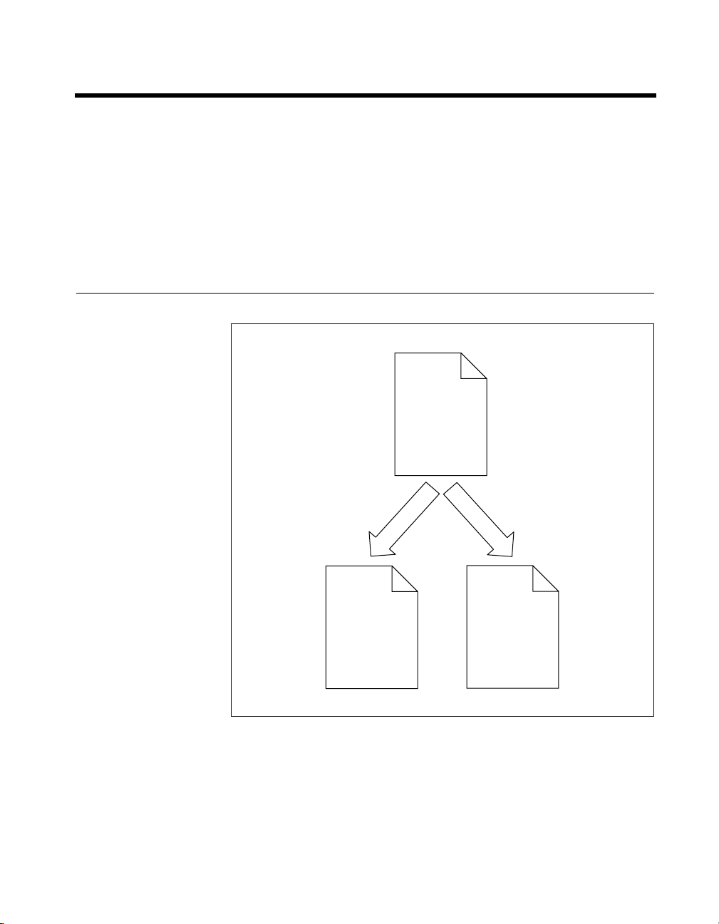
How to Use the Manual Set
VXI-1394
User Manual
(PDF Format)
Hardware and
Software
Reference
NI-VISA
Programmer
Reference Manual
(PDF and Online
Help Format)
NI-VISA
Reference
NI-VXI
Online Help
(Optional)
NI-VXI
Reference
This user manual contains an overview of the VXI-1394 hardware and the
NI-VXI/NI-VISA software, guides you through setting up your kit, and
helps you get started with application development. You can also use this
manual as a reference for the hardware and software default settings and to
find the answers to commonly asked questions.
© National Instruments Corporation vii VXI-1394 User Manual for Windows
Page 8

About This Manual
Note You can download Acrobat Reader from the Adobe Web site at www.adobe.com.
When you have successfully set up your system, you can begin to develop
applications in NI-VISA or NI-VXI. NI-VISA online manuals are included
in your kit in the form of Adobe Acrobat portable document format (PDF)
files. The NI-VXI Online Help presents the concepts of VXI and detailed
explanations of the NI-VXI functions. Study the descriptions of each
function given in the online help to fully understand the purpose and syntax
of each function.
The Acrobat manuals and their installed locations are as follows:
•The NI-VISA User Manual describes how to program using NI-VISA
and can be located at Start»Programs»VXIpnp»NI-VISA User
Manual.
•The NI-VISA Programmer Reference Manual describes in detail
the attributes, events, and operations you use in NI-VISA and can
be located at Start»Programs»VXIpnp»NI-VISA Programmer
Reference Manual.
Use the Acrobat Reader program to open the PDF files.
Conventions
The following conventions appear in this manual:
» The » symbol leads you through nested menu items and dialog box options
to a final action. The sequence File»Page Setup»Options directs you to
pull down the File menu, select the Page Setup item, and select Options
from the last dialog box.
This icon denotes a note, which alerts you to important information.
This icon denotes a caution, which advises you of precautions to take to
avoid injury, data loss, or a system crash.
bold Bold text denotes items that you must select or click in the software, such
as menu items and dialog box options. Bold text also denotes parameter
names.
italic Italic text denotes variables, emphasis, a cross reference, or an introduction
to a key concept. This font also denotes text that is a placeholder for a word
or value that you must supply.
VXI-1394 User Manual for Windows viii ni.com
Page 9

About This Manual
monospace Text in this font denotes text or characters that you should enter from the
keyboard, sections of code, programming examples, and syntax examples.
This font is also used for the proper names of disk drives, paths, directories,
programs, subprograms, subroutines, device names, functions, operations,
variables, filenames, and extensions.
monospace bold Bold text in this font denotes the messages and responses that the computer
automatically prints to the screen. This font also emphasizes lines of code
that are different from the other examples.
monospace italic
Italic text in this font denotes text that is a placeholder for a word or value
that you must supply.
Related Documentation
The following documents contain information that you may find helpful as
you read this manual:
• ANSI/IEEE Standard 1014-1987, IEEE Standard for a Versatile
Backplane Bus: VMEbus
• ANSI/IEEE Standard 1155-1998, IEEE VMEbus Extensions for
Instrumentation: VXIbus
• ANSI/VITA 1-1994, VME64
• IEEE Standard 1394-1995, IEEE Standard for a High Performance
Serial Bus
• PCI Local Bus Specification, Revision 2.1, PCI Special Interest Group
• VXI-6, VXIbus Mainframe Extender Specification, Rev. 2.0, VXIbus
Consortium
© National Instruments Corporation ix VXI-1394 User Manual for Windows
Page 10

Introduction
This chapter describes your VXI-1394 interface kit, lists what you need
to get started, and includes a brief description of the hardware and software.
1
The VXI-1394 interface kit links a PCI-based computer to the VXIbus
using the IEEE 1394, or FireWire
your computer perform as if it were plugged directly into the VXI
backplane, giving your external computer the capability of an embedded
computer. You can connect streaming devices such as digital cameras to
either the VXI-1394 interface in your VXI mainframe or the PCI-1394
interface in your computer. IEEE 1394 features hot plug-in capability
under Windows, which means you can add and configure 1394 devices
without powering down your system.
Your kit contains a National Instruments VXI-1394 interface module,
which plugs into your VXI mainframe and links your computer to the
VXIbus.
Your kit also contains an industry-standard OHCI host adapter, which links
your PCI-based computer to the IEEE 1394 bus.
Your kit includes the NI-VXI/NI-VISA bus interface software, which is
fully VXIplug&play compliant. NI-VXI/NI-VISA is the National
Instruments implementation of the VISA I/O software standard on which
all VXIplug&play software components are based.
What You Need to Get Started
To set up and use the VXI-1394 interface kit, you need the following items:
®
, high-speed serial bus. This kit makes
❑ A computer running Windows 2000/XP/Me/98 Second Edition
❑ An industry-standard OHCI host adapter
❑ VXIbus mainframe
❑ VXI-1394 interface module that plugs directly into a VXI mainframe
❑ 1394 cable
© National Instruments Corporation 1-1 VXI-1394 User Manual for Windows
Page 11
Chapter 1 Introduction
❑ National Instruments software CD
❑ This manual
VXI-1394 Interface Kit Overview
The interface kit described in this manual links a 1394-equipped computer
directly to the VXIbus using the IEEE 1394 bus. The VXI-1394 kit uses
this high-speed (up to 400 Mbits/s) serial bus to link your computer
running Windows to a VXI chassis.
Note You can connect multiple 1394 devices together in a tree topology. However,
increasing the complexity of the 1394 bus topology can lower overall system performance.
Caution You cannot connect multiple 1394 devices in a circular bus topology (one which
provides more than one data path between any two nodes). Doing so will render your
VXI-1394 inoperable and may crash your system.
The VXI-1394 kit includes the NI-VXI/NI-VISA software for Windows,
a C-size VXI-1394 module, a 1394 cable, and an industry-standard OHCI
host adapter.
A 1394-equipped computer connected to a VXI-1394 interface can
function as a VXI Commander and Resource Manager. The VXI-1394
interface kit gives your computer the capability to perform as if it is
plugged directly into the VXI backplane as an embedded CPU module.
The VXI-1394 transparently translates between the IEEE 1394 and
VXI protocols.
The software included with the kit is for Pentium-based computers.
Hardware Description
The VXI-1394 module is a VXIbus device with optional VXIbus Slot 0
capability so that it can reside in any slot in a C-size or D-size chassis.
If you enable this capability, the VXI-1394 can automatically determine
whether it is located in VXI Slot 0.
Note D-size VXI mainframes have connections for a P3 connector. The VXI-1394,
however, does not have this connector and, if configured as a Slot 0 controller, cannot
provide the necessary control for VXI devices that need P3 support.
VXI-1394 User Manual for Windows 1-2 ni.com
Page 12

Caution An improper Slot 0 setting may damage the VXI-1394 module and/or the VXI
chassis.
The VXI-1394 links the computer to the VXIbus and converts 1394 data
transfers into VXIbus data transfers and vice versa. The VXI-1394 includes
additional 1394 ports you can use to connect other 1394 devices.
The PCI-1394 is an industry-standard 1394 host adapter on a PCI board,
which gives your computer the capability to control 1394 devices. The
PCI-1394 also supplies power to the IEEE 1394 bus, which is required by
some devices.
VXI-1394 Front Panel Features
The VXI-1394 has the following front panel features.
• Three front panel LEDs
– SYSFAIL LED indicates that the VMEbus SYSFAIL line is
asserted.
– 1394 LED indicates when the VXI-1394 is accessed from the
IEEE 1394 bus.
– VXI LED indicates when the VXI-1394 is accessed from the
VXIbus.
• Three 1394 6-pin connectors
• Three SMB connectors
– External clock
– Trigger output
– Trigger input
• System reset push-button
Chapter 1 Introduction
Advanced Configuration Options
The default hardware configuration of the VXI-1394 should be
acceptable for most systems. Refer to Appendix C, Advanced Hardware
Configuration Settings, only if your system will make use of the front-panel
CLK10 and trigger SMB connectors.
© National Instruments Corporation 1-3 VXI-1394 User Manual for Windows
Page 13

Chapter 1 Introduction
Software Description
The NI-VISA/NI-VXI bus interface software includes a Resource
Manager, an interactive configuration and troubleshooting program,
a comprehensive library of software routines for VXI/VME programming,
a logging utility you can use for debugging, and graphical interactive
control programs for interacting with VISA. You can use this software to
seamlessly program multiple-mainframe configurations and have software
compatibility across a variety of controller platforms.
NI-VISA has a comprehensive library of software routines not only for
VXI/VME programming, but also for GPIB, GPIB-VXI, PXI, TCP/IP, and
Serial. You can use this software to program instruments connected through
different types of interfaces.
Measurement & Automation Explorer (MAX) helps you view your entire
test and measurement system and configure various components, whether
they are VXI, GPIB, PXI, or Serial devices. You can also add VME devices
to your system easily with MAX and view them on a screen display along
with the rest of your system.
MAX also features various options for running Resman. You can still
execute Resman independently to configure your instruments after a power
cycle. But you can also perform resource manager operations directly from
MAX or configure it to run Resman automatically at startup.
The NI Spy utility tracks the calls your application makes to National
Instruments drivers, including NI-VXI, NI-VISA, and NI-488.2. NI Spy
helps you debug your application by clearly highlighting the functions that
return errors. You can let NI Spy keep a log of your program’s calls to these
drivers so that you can check them for errors at your convenience.
National Instruments Application Software
In addition to the NI-VISA/NI-VXI software, you can use the National
Instruments LabVIEW, Measurement Studio, and LabWindows
application programs and instrument drivers to ease your programming
task. These standardized programs match the modular virtual instrument
capability of VXI and can reduce your VXI/VME software development
time. These programs are fully VXIplug&play compliant and feature
extensive libraries of VXI instrument drivers written to take full
advantage of direct VXI control. LabVIEW, Measurement Studio,
and LabWindows/CVI include all the tools needed for instrument control,
data acquisition, analysis, and presentation.
VXI-1394 User Manual for Windows 1-4 ni.com
™
/CVI™
Page 14

Chapter 1 Introduction
LabVIEW is an easy-to-use, graphical programming environment you can
use to acquire data from thousands of different instruments, including
IEEE 488.2 devices, VXI devices, serial devices, PLCs, and plug-in data
acquisition boards. After you have acquired raw data, you can convert it
into meaningful results using the powerful data analysis routines in
LabVIEW. LabVIEW also comes with hundreds of instrument drivers,
which dramatically reduce software development time, because you do not
have to spend time programming the low-level control of each instrument.
Measurement Studio allows you to choose from standard environments
such as Microsoft Visual Basic, Visual C++, and Visual Studio .NET
to create your application, using tools specific for each language. With
Measurement Studio, you can write programs quickly and easily and
modify them as your needs change.
LabWindows/CVI is an interactive ANSI C programming
environment designed for building virtual instrument applications.
LabWindows/CVI delivers a drag-and-drop editor for building user
interfaces, a complete ANSI C environment for building your test program
logic, and a collection of automated code generation tools, as well as
utilities for building automated test systems, monitoring applications,
or laboratory experiments.
To use any of these application programs, install them before the
NI-VISA/NI-VXI software installation. LabVIEW, Measurement Studio,
and LabWindows/CVI integrate the VXI and VISA libraries that are
required to support your VXI-1394. You also get hundreds of complete
instrument drivers, which are modular, source-code programs that handle
the communication with your instrument to speed your application
development.
© National Instruments Corporation 1-5 VXI-1394 User Manual for Windows
Page 15

Installation and Configuration
This chapter explains how to set up your test system.
Installing the Software
Use the Setup program that came with your NI-VXI/NI-VISA software to
install the entire software package or a software update, or to reinstall
software in the event that your files were accidentally erased.
Some of the utilities rely on the LabWindows/CVI Run-Time Engine. This
software is installed, if necessary, during the NI-VXI/NI-VISA installation.
Depending on the type of installation you choose, you may need up
to 50 MB of free space available on your hard drive to accommodate the
NI-VXI and NI-VISA software.
To be compliant with VXIplug&play specifications, a VXI controller must
provide the VISA I/O driver library standardized by VXIplug&play. VISA
ensures that your controller can run all VXIplug&play-compatible software
now and in the future.
2
The NI-VISA software in this kit is compatible with the WINNT/GWINNT
and WIN95/GWIN95 frameworks. With NI-VISA installed on your
computer, you can run any VXIplug&play software that is compatible with
these frameworks. This includes instrument drivers and executable soft
front panel software that are included with VXIplug&play-compatible
instruments from a variety of vendors.
Installing the NI-VXI and NI-VISA Software
This section describes how to install the NI-VXI and NI-VISA software.
Please carefully read these directions along with any messages on the
screen before making your selections.
You can quit the Setup program at any time by pressing the Cancel button.
© National Instruments Corporation 2-1 VXI-1394 User Manual for Windows
Page 16

Chapter 2 Installation and Configuration
Setup is an interactive, self-guiding program that installs the NI-VXI and
NI-VISA software and configures your system to use the software with the
VXI-1394. Complete the following steps to perform the installation.
Caution If you want to keep the manufacturer/model name tables or the VME device
configuration from a previous installation, be sure to back them up before starting Setup.
They are in the
TBL subdirectory of your NI-VXI directory.
1. For the CD, select Start»Run and enter the following text, where
your CD drive (usually D):
X
and press <Enter>. Typically, this setup program runs automatically
when you insert the CD.
2. Click the Next button at the Welcome screen to start the installation
and accept the license agreement.
Note If you have a previous 32-bit (Windows NT/98) version of the NI-VXI software
installed, Setup installs the new version over the previous version.
3. Select the type of installation from the Installation Options screen.
• Typical setup installs runtime support and NI-VISA development
• Complete setup installs everything including NI-VXI API
• Custom setup gives you more control over which driver
4. Click the Next button. Confirm that you are ready to install, and click
Next again to begin the installation.
5. Setup now copies the necessary files to your hard drive and creates
program icons.
:\NIVXI\setup.exe
support.
development support. For more information about the NI-VXI
API, refer to Chapter 3, Developing Your Application.
components you want installed on your system. This option is
recommended for advanced users.
X
is
VXI-1394 User Manual for Windows 2-2 ni.com
Page 17
Completing the Software Installation
1. Please review the information in any README files that Setup prompts
you to read.
2. When the installation process completes, power off the system for the
changes to take effect.
If you backed up the manufacturer and model name files, restore them to
the
TBL subdirectory of your NI-VXI directory before running MAX.
Configuring the Hardware (optional)
This section contains basic information about configuring your VXI-1394
hardware. Because the default settings for your VXI-1394 hardware are
acceptable for most typical applications, this section is optional.
Refer to Appendix B, Default Settings, for a complete listing of the
hardware and software default settings. Refer to Appendix C, Advanced
Hardware Configuration Settings, if you want information about other
possible settings.
Use MAX to change any of the configuration settings for the VXI-1394.
For information on the software, including optional settings, use MAX and
its online help. Use the Windows Start menu to open the program group
for National Instruments, launch MAX and select Help»Help Topics.
Chapter 2 Installation and Configuration
Installing the Hardware
This section summarizes how to install your VXI-1394 hardware. Your kit
contains a VXI-1394 interface module and a PCI-1394 adapter board.
Caution To guard against electrostatic discharge, touch the antistatic plastic packages to
a metal part of your computer or chassis before removing the boards from their packages.
Your computer or chassis should be plugged in but powered off.
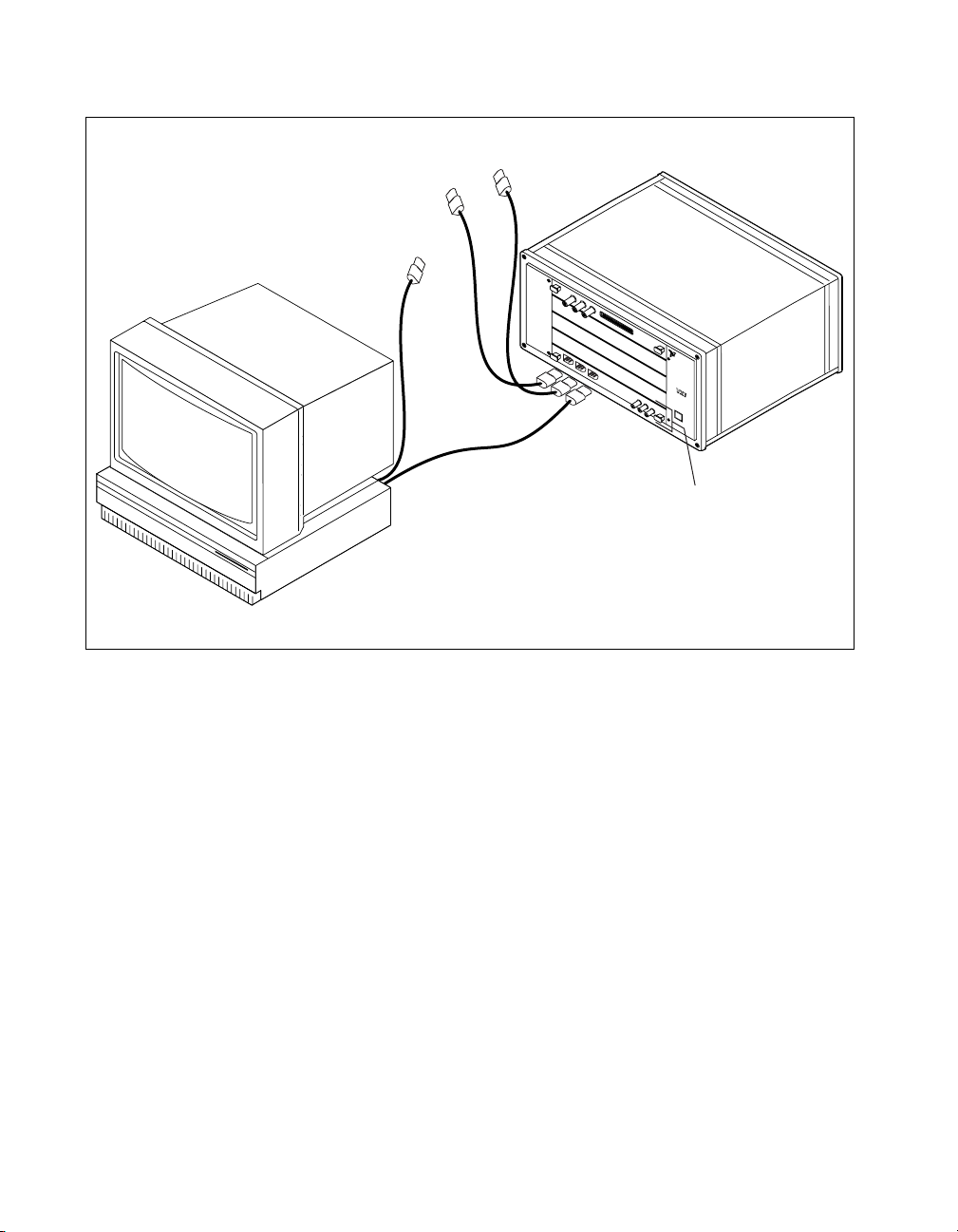
Figure 2-1 shows a system that includes an IEEE 1394-equipped computer,
a VXI-1394 and IEEE 1394 devices. Each 1394 device should have only
one connection to the 1394 system.
© National Instruments Corporation 2-3 VXI-1394 User Manual for Windows
Page 18
Chapter 2 Installation and Configuration
To Other IEEE 1394 Devices
IEEE 1394
Cables
N
A
IN
T
I
S
O
T
N
R
A
UM
L
E
N
TS
®
b
us
VXI-1394
in Slot 0
VXI Mainframe
External Computer
Figure 2-1. Typical VXI-1394 System
Installing Your PCI-1394 Interface Board
To install the PCI-1394 interface board, complete the following steps.
1. Shut down and power off the computer.
2. Remove the computer chassis cover to expose the expansion slots and
external access covers.
3. Select an available PCI slot in your computer. The slot you select
should support bus mastering. Refer to your computer documentation
to determine if the slot you select supports bus mastering.
4. Remove the corresponding expansion slot cover from the chassis.
VXI-1394 User Manual for Windows 2-4 ni.com
Page 19
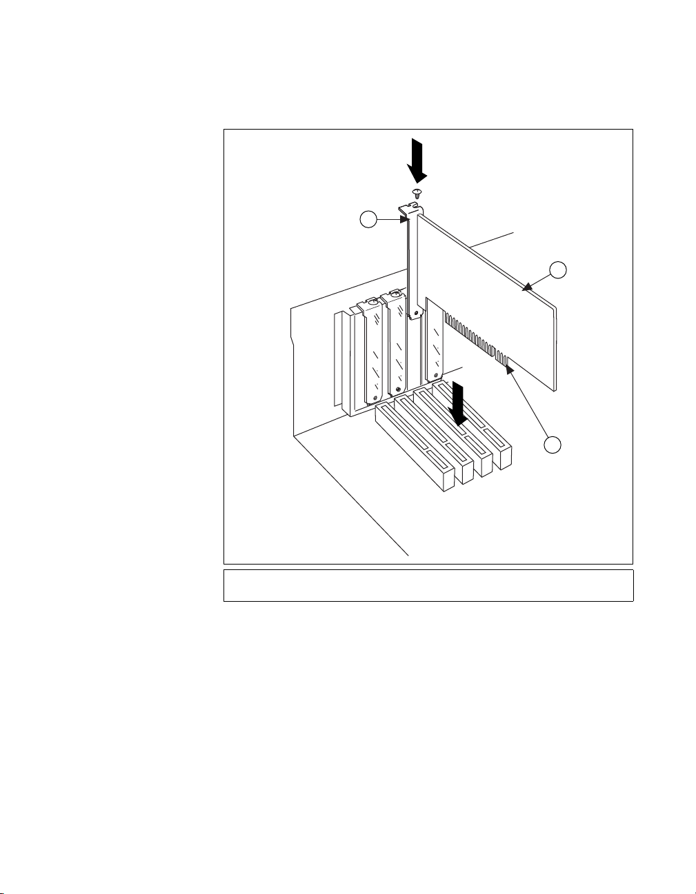
Chapter 2 Installation and Configuration
5. Align the bus connector on the bottom of the host adapter with the
PCI bus slot.
1
2
3
1 Host Adapter Mounting Bracket
2 Host Adapter
3 Bus Contacts
Figure 2-2. Installing the PCI-1394 Host Adapter
6. Carefully press the host adapter into the slot.
7. Secure the host adapter bracket to the computer chassis with the screw
from the removed expansion slot cover.
© National Instruments Corporation 2-5 VXI-1394 User Manual for Windows
Page 20
Chapter 2 Installation and Configuration
Installing Your VXI-1394 Interface Board
All kits contain a VXI-1394 interface module.
To install the VXI-1394 in Slot 0 of your VXI chassis, complete the
following steps.
1. Power off the chassis.
2. Insert the VXI-1394 into the chassis in Slot 0, as shown in Figure 2-1.
3. Power on the chassis.
The VXI-1394 default configuration automatically detects whether it
should be the VXI system controller. The VXI system controllers operate
certain VXI lines as required for VXI systems. Verify that any other VXI
devices with system controller capability that are located in the same
chassis are not configured as system controller.
Caution Having more than one device configured as system controller can damage the
VXI system.
For VXI systems that include VME devices, ensure that the VME devices
are not configured in the upper 16 KB (starting from 0xC000) of the
A16 address space. This region is reserved for VXI device configuration
registers, which are used for initializing, configuring, and interacting with
VXI devices. The VXI-1394 also uses this region for this purpose.
Note Also ensure that no VXI devices in your system are configured for logical address 0.
This is the default configuration for the VXI-1394.
Connecting Cables
Connect the IEEE 1394 cable to the PCI-1394 host adapter and to the
VXI-1394, as shown in Figure 2-1. You can use any available 1394 port for
each device. The VXI-1394 has three external ports. The OHCI 1394 host
adapter has three external ports.
You can connect any other 1394 devices to any available port on an existing
device, but for best results minimize the number of levels in the tree
topology. Adding to the number of levels in the tree degrades system
performance.
Caution Do not cable devices to your 1394 system in such a way as to form a loop. Any
device should have only one connection to the 1394 bus. An example of a loop would be a
system containing a PCI-1394, a VXI-1394, and a device connected to both. Such a closed
loop would break the 1394 system.
VXI-1394 User Manual for Windows 2-6 ni.com
Page 21

Some 1394 devices require different cables than others. Your kit includes
one 6-to-6-pin cable to link the VXI-1394 to your computer. Some other
devices also require a 6-to-6-pin cable for proper connection to the 1394
system. Many other devices such as camcorders, VCRs, and so on, take a
6-to-4-pin cable.
Powering on the System
1. Be sure all cables are connected securely.
2. Ensure that the VXI-1394 is powered on prior to starting the external
computer.
3. Power on the external computer.
4. If your system CMOS setup requires you to enable PCI bus
parameters, do so at this time.
Note The PCI bus usually assigns IRQs and port addresses automatically. However, in
some PC systems, you may need to manually edit the PCI bus parameters in your CMOS
setup. Refer to your computer documentation for further instructions.
5. You can now power on any external devices.
Chapter 2 Installation and Configuration
Software Configuration and Verification
Running MAX and Resman
1. Run the MAX program. You must run Resman every time the chassis
or computer power is cycled so that your application can access
devices in the VXI chassis. You can also configure MAX to run
Resman automatically at every computer startup by selecting Tools»
NI-VXI»VXI Options and selecting the appropriate checkbox.
2. After you run Resman, you are ready to use MAX to interactively
configure the National Instruments hardware in your system. Use the
right-click help for information about the various configuration
options.
After you finish configuring the system through MAX, verify the
configuration through one of the interactive control utilities. Use VIC
under NI-VXI (Start»Programs»National Instruments»VXI»NI-VXI
API»VIC) or VISAIC under NI-VISA (Start»Programs»National
Instruments»VISA»VISA Interactive Control).
© National Instruments Corporation 2-7 VXI-1394 User Manual for Windows
Page 22

Developing Your Application
This chapter discusses the software utilities you can use to start developing
applications that use NI-VXI.
After installing the NI-VXI software, you can begin developing your
VXI/VME application. Be sure to check the release notes for the latest
application development notes and changes.
NI-VXI, NI-VISA, and Related Terms
Before you develop your application, it is important to understand the
difference between NI-VXI, NI-VISA, and similar terms.
• NI-VXI is the software package that ships with National Instruments
VXI and VME controllers. NI-VXI includes Measurement &
Automation Explorer (MAX), NI-VISA, NI Spy, Resource Manager
(Resman), VXI device drivers, and other utilities for configuring and
controlling your VXI or VME system.
• NI-VISA is the native API for communicating with VXI/VME devices.
NI-VISA is the National Instruments implementation of the VISA I/O
standard, which is a common interface to many types of instruments
(such as VXI, GPIB, PXI, Serial, TCP/IP, and so on). NI-VXI is
optimized for use through NI-VISA, and NI recommends using
NI-VISA to develop all new VXI/VME applications.
•The NI-VXI API is an optional development environment that is not
part of the default NI-VXI installation. The NI-VXI API was
developed before NI-VISA; whereas NI-VXI still supports the
NI-VXI API, NI recommends using NI-VISA for all new VXI/VME
applications. If you must develop an application using the older
NI-VXI API, run the NI-VXI installer and perform a Complete install
and select the appropriate option in the custom installation screen.
Be sure to review the NI-VXI API Notes section.
•The NI-VXI compatibility layer allows older programs that use the
NI-VXI API to communicate with VXI devices through VISA. Using
this compatibility layer, older programs can run in NI-VXI 3.0 or later
without being rewritten to use the VISA interface. This layer installs
with NI-VXI by default. It should be completely transparent and
3
© National Instruments Corporation 3-1 VXI-1394 User Manual for Windows
Page 23

Chapter 3 Developing Your Application
provide a high level of performance; however, there may be some
slight changes in behavior for certain applications.
Your software features several system development utilities including
MAX, Resman, NI Spy, VISA Interactive Control (VISAIC), and VXI
Interactive Control (VIC, optional). You can also access online help and
a variety of examples to learn how to use NI-VXI for certain tasks.
Each component assists you with one of four development steps:
configuration, device interaction, programming, and debugging.
You can access the utilities, help files, and release notes through the
Windows Start menu by opening the National Instruments»VXI
or National Instruments»VISA program groups.
Configuration
The configuration utilities in your software kit are Resman and MAX.
Resman performs VXI Resource Manager functions as described in the
VXIbus specification. Resman configures all devices on the VXI backplane
for operation and allocates memory for devices that request it. Resman does
not require you to specify any settings; it automatically performs the VXI
resource management whenever you run it.
Note Power cycling resets all devices, so you must run Resman to reconfigure your
system every time you cycle the power on the chassis.
MAX presents a graphical display of your entire test and measurement
system to help you configure various components. When you launch MAX,
you see all your devices (including VXI) on the screen. You can view the
properties (such as logical address, address space, and so on) of each device
by clicking the device in the configuration tree. To see additional
configuration options for a given device, right-click the device in the
configuration tree. When you access the properties of most National
Instruments devices by right-clicking, you can configure the hardware
settings by selecting Hardware Configuration.
MAX and Resman are designed to work together. You can run Resman
through MAX by either clicking the Run VXI Resource Manager button
in the toolbar or right-clicking a specific VXI system on which to run
Resman, as shown in Figure 3-1. You can also select Tools»NI-VXI»VXI
Resource Manager to run Resman on all VXI systems. From the VXI
VXI-1394 User Manual for Windows 3-2 ni.com
Page 24

Chapter 3 Developing Your Application
Options dialog box in the Tools»NI-VXI menu, you can also use MAX to
configure Resman to run on all VXI systems automatically when the
computer boots. Resman reports to MAX all errors it finds in your system.
When you view your VXI system in MAX, you can easily spot any errors
that Resman found while configuring the system.
Figure 3-1. Right-Click a VXI System in MAX to Run Resman on that System
After Resman detects and configures all your VXI/VME devices, you can
use MAX to view specific information about each device in your system.
The default MAX view of a VXI system shows the General tab window,
which contains a summary of key information about each device, including
its device name, logical address, model name, and other data.
For more information about MAX, refer to its online help by selecting the
Help»Help Topics menu.
© National Instruments Corporation 3-3 VXI-1394 User Manual for Windows
Page 25

Chapter 3 Developing Your Application
Device Interaction
You can interact with your VXI/VME devices using the VISA Interactive
Control (VISAIC) utility. VISAIC allows you to control your VXI/VME
devices without using LabVIEW, Measurement Studio, or another
programming language. You can also control your devices in MAX by
right-clicking a device name and selecting Open VISA Session.
Note You can also use VXI Interactive Control Program (VIC) to control your VXI/VME
devices and develop and debug VXI application programs. VIC is not included in the
default NI-VXI installation. To install VIC, choose either a Complete install or select
NI-VXI API Development from the custom installation screen in the installer.
You can launch VISAIC (or VIC) from the Tools menu in MAX or from
the VISA or VXI subgroups in Start»Programs»National Instruments.
Try the following in VISAIC: In the tree view, navigate using your mouse
to the VISA resource for your controller—probably VXI0::0::INSTR,
representing the VXI system 0, logical address 0 instrument resource,
as shown in Figure 3-2.
Figure 3-2. Select Your Controller in VISAIC
VXI-1394 User Manual for Windows 3-4 ni.com
Page 26

Chapter 3 Developing Your Application
Open the selected resource and navigate to the Register I/O tab. In this tab,
you can read registers on your device, such as the VXI device configuration
registers. Execute the viIn operation (called In in LabVIEW compatibility
mode) with the default parameters. The Data Value field shows the I/O
operation result, such as
function status, such as
0x9ff6. The Return Value field shows the
0 for VI_SUCCESS, as shown in Figure 3-3.
Figure 3-3. Successful viIn Access in the VISAIC Register I/O Tab
(This Dialog Box May Look Slightly Different for LabVIEW Users)
If the data value ends in ff6, you have successfully read the National
Instruments manufacturer ID from your VXI/VME controller’s ID register.
You may now want to read the configuration registers from other VXI
devices in your system by opening the devices in VISAIC. Try reading a
register from each device listed in the MAX view of your VXI system. This
way, you can verify that your VXI controller can access each device in your
VXI system successfully.
You can also access VXI and VME devices configured in A16, A24, or A32
space by opening the VXI MEMACC resource, which is VISA’s
representation of VXI memory. For more information about VISAIC
operations and commands, refer to the online help in the Help menu
and the context-sensitive help (such as What’s This?), available by
right-clicking in any panel.
© National Instruments Corporation 3-5 VXI-1394 User Manual for Windows
Page 27

Chapter 3 Developing Your Application
Programming for VXI
NI-VISA and the NI-VXI API are the two National Instruments
programming interfaces for accessing your VXI/VME instruments. With
NI-VXI 3.0 or later, NI-VISA is the native API for communicating with a
VXI or VME system, and NI recommends using it for all new applications.
Older programs that use the NI-VXI API now use the NI-VXI-to-NI-VISA
compatibility layer to communicate with the VXI devices. Using this layer,
older programs can run in NI-VXI 3.0 or later without being rewritten to
use the VISA interface.
Note The NI-VXI API development environment is not installed by default as part of the
NI-VXI installation. If you must develop an application using the older NI-VXI API, run
the NI-VXI installer and perform a Complete install or select the appropriate option in the
custom installation screen. Be sure to review the NI-VXI API Notes section.
NI-VISA is the National Instruments implementation of the VISA API as
the VXIplug&play standard defines. It provides a common interface to
many types of instruments (such as VXI, GPIB, PXI, Serial, TCP/IP, and
so on) and therefore is especially useful in situations where you are using
multiple types of instruments.
Both NI-VISA and the NI-VXI API include functions for register-level
access to VXI instruments and messaging capability to message-based
devices. You can also use either interface to service asynchronous events
such as triggers, signals, and interrupts, and also assert them. Compatibility
with the NI-VXI API is included for legacy applications only—NI
recommends that you write all new VXI/VME applications in VISA.
The best way to learn NI-VISA programming is by reviewing the example
programs your software includes. The examples directory contains working
VISA programs that illustrate many different types of applications. You can
find these examples in the
If you are just getting started, you should learn how to access registers with
high-level calls and send messages with word-serial functions. The
NI-VISA examples for these tasks are
the other examples as you try more advanced techniques. Consult the
NI-VISA User Manual or online help for additional information on these
topics.
VXI-1394 User Manual for Windows 3-6 ni.com
VXIpnp\WinNT\NIvisa\Examples directory.
HighReg.c and RdWrt.c. Refer to
Page 28

Chapter 3 Developing Your Application
Table 3-1 summarizes the topics the example programs address. All files
are in the
VXIpnp\WinNT\NIvisa\Examples directory, in the
subdirectories listed below.
Table 3-1. NI-VISA/NI-VXI Examples
NI-VXI Example
Coverage NI-VISA Example
(Optional)
Message-Based
Access
High-Level
Register Access
Low-Level
Register Access
Sharing Memory
Interrupt Handling VXI-VME\AsyncIntr.c
Trigger Handling
Note MAX includes configuration options that affect low-level functions and shared
memory, as well as trigger mappings and other attributes of your VXI system. Refer to the
MAX online help for information regarding these options.
Optimizing Large VXIbus Transfers
For best performance, keep the following in mind when using viMove()
or
VXImove():
• Make sure your buffers are 32-bit aligned.
• Transfer 32-bit data whenever possible.
• Use VXI block access privileges to significantly improve performance
to devices that are capable of accepting block transfers.
• To optimize move performance on virtual memory systems, lock the
user buffer in memory yourself so the move operation does not need to
lock the buffer.
• To optimize move performance on paged memory systems, use
a contiguous buffer so the move operation does not need to build
a scatter-gather list for the user buffer.
General\RdWrt.c VXIws.c
VXI-VME\HighReg.c VXIhigh.c
VXI-VME\LowReg.c VXIlow.c
VXI-VME\ShareSys.c VXImem.c
VXIint.c
and
WaitIntr.c
VXI-VME\WaitTrig.c VXItrig.c
© National Instruments Corporation 3-7 VXI-1394 User Manual for Windows
Page 29

Chapter 3 Developing Your Application
Note viMemAlloc() or VXImemAlloc() returns 32-bit aligned, page-locked,
continuous buffers which work efficiently with the move operations.
Shared Memory
In the Hardware Configuration settings for your controller in MAX, you
can share memory from your computer to the VXI bus. Right-click any
setting or consult the MAX online help for more information. You can
access shared memory on your computer using
VXImemAlloc() in the NI-VXI API). Use MAX to view the VXI
(or
address where your shared RAM is allocated, or determine this information
programmatically using VISA’s
NI-VXI API Notes
The following notes apply only if you are using the NI-VXI API. We
recommend that all new VXI/VME applications use the NI-VISA API,
but you can still develop with the older NI-VXI API for compatibility with
legacy code.
Compiler Symbols
You may need to define certain compiler symbols so that the NI-VXI
library can work properly with your program. The required symbol
indicates your operating system platform; for example,
the application as a Windows 2000/NT/XP/Me/98 application.
viMemAlloc() in VISA
viGetAttribute().
VXINT designates
Note LabWindows/CVI automatically defines the correct symbol. You do not need to
define
VXINT when using LabWindows/CVI.
The additional symbol
BINARY_COMPATIBLE is optional. It ensures that
the resulting application is binary compatible with other National
Instruments VXI controllers using the same operating system. This symbol
may cause a slight performance degradation when you use low-level
VXIbus access functions.
You can define these symbols using
code or using the appropriate option in your compiler (typically either
or
/D). If you use #define statements, they must appear in your code
before the line that includes the NI-VXI API header
VXI-1394 User Manual for Windows 3-8 ni.com
#define statements in your source
-D
nivxi.h.
Page 30

Chapter 3 Developing Your Application
Compatibility Layer Options
Although NI-VXI supports multiple VXI controllers through NI-VISA, the
NI-VXI API supports only a single controller. To specify which controller
the emulation layer should use, run MAX. Select Tools»NI-VXI»VXI
Options. Select the VXI system that will support the emulation layer.
In NI-VXI 3.0 or later, when you enable for triggers or interrupts, only the
local controller is enabled. In the NI-VXI API functions for enabling
triggers and interrupts, the controller parameter is ignored. If you need to
enable a remote controller for triggers, use the MAX frame resource to map
the trigger back to the local controller.
The interrupt and trigger routing in the NI-VXI 3.0 or later low-level
drivers is somewhat different from the default routing in previous versions
of NI-VXI. Therefore, the compatibility layer may behave differently than
the original NI-VXI API with regard to these settings. In particular, if you
are receiving triggers on an external controller, you may need to modify the
trigger configuration on your extender module using MAX. In general,
interrupts are routed automatically based on the interrupt configuration the
resource manager detects. Whether the changed routing behavior affects
your program is application dependent.
Because VISA is an instrument-centric API, certain functions from the
more controller-centric NI-VXI API do not match perfectly with a VISA
counterpart. When an application enables an event with the NI-VXI API
compatibility layer, each logical address is enabled for that event
separately. For example, if the application enables an interrupt level, VISA
will enable the interrupt on each logical address, one at a time, until all the
devices are enabled. This means that some interrupts could be lost from
devices with higher numbered logical addresses. MAX provides an
option for users to pick which logical address is enabled first. Select
Tools»NI-VXI»VXI Options. Set Prioritized Signal LA to the logical
address of the device that generates the events. This prevents possible loss
of events from that device.
© National Instruments Corporation 3-9 VXI-1394 User Manual for Windows
Page 31

Chapter 3 Developing Your Application
Debugging
NI Spy and VISAIC are useful utilities for identifying the causes of
problems in your application.
NI Spy tracks the calls your application makes to National Instruments
programming interfaces, including NI-VISA, NI-VXI, and NI-488. NI Spy
highlights functions that return errors, so during development you can
quickly spot which functions failed during a program’s execution. NI Spy
can log the calls your program makes to these drivers so you can check
them for errors at your convenience, or use the NI Spy log as a reference
when discussing the problem with National Instruments technical support.
Figure 3-4 shows an example of a normal error returned from a call to
viMemAlloc when no memory has been shared.
Figure 3-4. NI Spy
VXI-1394 User Manual for Windows 3-10 ni.com
Page 32

Chapter 3 Developing Your Application
VISAIC, discussed in the Device Interaction section, is an excellent
platform for quickly testing instruments and learning how to communicate
with them.
Figure 3-5. VISAIC
© National Instruments Corporation 3-11 VXI-1394 User Manual for Windows
Page 33

Specifications
This appendix lists the specifications for the VXI-1394 module.
VXI Requirements
VXIbus configuration space................... 64 B
A24 or A32 space...................................Programmable
Default ............................................ None
Power Requirement
+5 V
Typical ............................................ 2.23 A
Maximum (fused) ........................... 7 A
–5.2 V
Typical ............................................176 mA
Maximum (fused) ........................... 1 A
A
–2 V
Typical ............................................ 89.5 mA
Maximum (fused) ........................... 1 A
+12 V
Typical ............................................750 µA
Maximum (fused) ........................... 1 A
Physical
Dimensions
Fully enclosed, shielded VXI C-size board
233.35 mm × 340 mm (9.187 in. × 13.386 in.)
Weight
VXI-1394 ........................................ 1.11 kg (2.45 lb)
(No DRAM installed)
© National Instruments Corporation A-1 VXI-1394 User Manual for Windows
Page 34

Appendix A Specifications
I/O connectors
Slot requirements....................................Single VXI C-size slot
Compatibility ..........................................Fully compatible with
VXI keying class ....................................Class 1 TTL
MTBF .....................................................Contact factory
Operating Environment
Ambient temperature range .................. 0 to 55 °C
Relative humidity range..........................10% to 90%, noncondensing
6-pin 1394........................................3
SMB.................................................3
GPIB (optional) ...............................1
VXI specification
(Tested in accordance with
IEC-60068-2-56.)
Altitude ...................................................2000 m (at 25 °C ambient
Pollution Degree .....................................2
For indoor or enclosed area use only.
Storage Environment
Ambient temperature range ....................–20 to 70 °C (Tested in
Relative humidity range..........................5% to 95% noncondensing
temperature)
accordance with IEC-60068-2-1
and IEC-60068-2-2.)
(Tested in accordance with
IEC-60068-2-56.)
VXI-1394 User Manual for Windows A-2 ni.com
Page 35

Shock and Vibration
Safety
Appendix A Specifications
Operational shock .................................. 30 g peak, half-sine, 11 ms pulse
(Tested in accordance with
IEC-60068-2-27. Test profile
developed in accordance with
MIL-PRF-28800F.)
Random vibration
Operating ........................................ 5 to 500 Hz, 0.3 g
rms
(with solid-state hard drive)
Nonoperating .................................. 5 to 500 Hz, 2.4 g
rms
(Tested in accordance with IEC-60068-2-64. Nonoperating test profile
exceeds the requirements of MIL-PRF-28800F, Class B.)
This product is designed to meet the requirements of the following
standards of safety for electrical equipment for measurement, control,
and laboratory use:
• IEC 61010-1, EN 61010-1
• UL 61010-1
• CAN/CSA-C22.2 No. 61010-1
Note For UL and other safety certifications, refer to the product label or to
ni.com/certification, search by model number or product line, and click the
appropriate link in the Certification column.
Electromagnetic Compatibility
Emissions ............................................... EN 55011 Class A at 10 m
FCC Part 15A above 1 GHz
Immunity................................................ EN 61326:1997 + A2:2001,
Table 1
EMC .......................................................CE, C-Tick, and FCC Part 15
(Class A) compliant
Note For full EMC compliance, operate this device with shielded cabling.
© National Instruments Corporation A-3 VXI-1394 User Manual for Windows
Page 36

Appendix A Specifications
CE Compliance
This product meets the essential requirements of applicable European
Directives, as amended for CE marking, as follows:
Low-Voltage Directive (safety)..............73/23/EEC
Electromagnetic Compatibility
Directive (EMC) .....................................89/336/EEC
Note Refer to the Declaration of Conformity (DoC) for this product for any additional
regulatory compliance information. To obtain the DoC for this product, visit
ni.com/certification, search by model number or product line, and click the
appropriate link in the Certification column.
IEEE 1394 Capability Descriptions
Speed support .........................................100, 200, and 400 Mbits/s
Protocol support......................................Asynchronous Quadlet and Block
Data payload packet sizes.......................Up to 2,048 bytes
Asynchronous target and initiator
VMEbus Capability Codes
A32, A24, A16 (master)
VMEbus master A32, A24, and A16 addressing
A32, A24, A16 (slave)
VMEbus slave A32, A24, and A16 addressing
D64, D32, D16, D08(EO) (master)
VMEbus master D64, D32, D16, and D08 data sizes
D64, D32, D16, D08(EO) (slave)
VMEbus slave D64, D32, D16, and D08 data sizes
BLT, MBLT (master)
VMEbus master block and D64 transfers
BLT, MBLT (slave)
VMEbus slave block and D64 transfers
VXI-1394 User Manual for Windows A-4 ni.com
Page 37

RMW (master)
VMEbus master read/modify/write transfers
RMW (slave)
VMEbus slave read/modify/write transfers
RETRY (master)
VMEbus master retry support
RETRY (slave)
VMEbus slave retry support
FSD
First slot detector
SCON
VMEbus System Controller (Automatic Detection)
PRI, RRS
Prioritized or Round Robin Select arbiter
Appendix A Specifications
ROR, FAIR
Release on Request and FAIR bus requester
IH(7-1)
Interrupt handler for levels 7–1
I(7-1)
Interrupt requester for levels 7–1
D32, D16, D08(O) (Interrupt Handler)
VMEbus D32, D16, D08(O) interrupt handler
D32, D16, D08(O) (Interrupter)
VMEbus D32, D16, D08(O) interrupter
ROAK, RORA
Release on Acknowledge or Register Access interrupter
BTO(
x)
VMEbus bus timer (programmable limit)
© National Instruments Corporation A-5 VXI-1394 User Manual for Windows
Page 38

Appendix A Specifications
LOCK
Can lock the VMEbus for indivisible transfers
VXI-1394 User Manual for Windows A-6 ni.com
Page 39

Default Settings
This appendix summarizes the default settings for the hardware and
software in the VXI-1394 kit. If you need more information about a
particular setting, or if you want to try a different configuration, refer
to Appendix C, Advanced Hardware Configuration Settings, for your
hardware reference and to the MAX online help for your software
reference.
Note There are no hardware settings on the PCI-1394 board.
Hardware Settings
Hardware Component Default Setting
W1—VXIbus Slot 0/Non-Slot 0 Automatic detection
S6—VXIbus CLK10 source From onboard oscillator
B
Table B-1. VXI-1394 Hardware Default Settings
S5—External trigger termination OFF: unterminated
S3—SMB CLK10 direction IN: receive CLK10 signal
S2—SMB CLK10 termination OFF: ignored
S4—Polarity of external SMB
CLK10
S7— Configuration EEPROM Do not load from factory setting
© National Instruments Corporation B-1 VXI-1394 User Manual for Windows
Inverted
Page 40

Appendix B Default Settings
Software Settings
Logical address 0
Device class Message based
Size of Servant area 0
System interrupt level Disabled
Number of handlers 1
Number of interrupters 0
Memory sharing Do not share memory
Table B-2. MAX Device Tab Default Settings
Editor Field Default Setting
Table B-3. MAX Shared Memory Tab Default Settings
Editor Field Default Setting
Shared RAM size A16—N/A
A24—256 B
A32—64 KB
Reserved physical memory 0
Lower half window byte swapping Disabled
Upper half window byte swapping Disabled
Map upper and lower halves at
same PCI address
VXI-1394 User Manual for Windows B-2 ni.com
Disabled
Page 41

Appendix B Default Settings
Table B-4. MAX VXI Bus Tab Default Settings
Editor Field Default Setting
Bus timeout value 125 µs
VXI retry generation Enabled
Automatic retries Disabled
A24/A32 write posting Disabled
Transfer limit 256
Requester mode Release on Request
Request level 3
Fair requester Enabled
Bus arbitration mode Prioritized
Arbiter timeout Enabled
© National Instruments Corporation B-3 VXI-1394 User Manual for Windows
Page 42

Advanced Hardware
Configuration Settings
This appendix describes the factory-default and alternate hardware
configuration settings of the VXI-1394. The board is set at the factory
for the most commonly used configuration. Use this appendix if you
want to try a different hardware configuration or if you would like more
information on a particular setting. This information is intended for more
advanced users.
Hardware Default Settings
The following hardware configuration settings are user configurable.
• VXIbus Slot 0/Non-Slot 0
• Configuration EEPROM
• VXIbus CLK10 routing
• Trigger input termination
C
Figure C-1 shows the factory-default settings of the user-configurable
jumper and switches on the VXI-1394. The slot selection jumper and
six switches are located in the corner of the board behind the front panel
SMB connectors.
Note Do not attempt an alternate setting unless you are familiar with its purpose.
In addition, do not reconfigure any switches or jumpers not described in this appendix
unless directed by National Instruments support.
© National Instruments Corporation C-1 VXI-1394 User Manual for Windows
Page 43

Appendix C Advanced Hardware Configuration Settings
TERMINATE
YN
S1
OUT IN
S2
NON INV
S3
SMB
TRIG TERM
YN
S4
CLK10 SOURCE
SMB ONBRD
S5
SLOT0
AUTO
W1 NON-
SLOT0
EXT
CLK10
LOAD FACTORY
FACTORY USER
S6
Figure C-1. VXI-1394 Default Configuration Settings
VXI-1394 User Manual for Windows C-2 ni.com
Page 44

VXIbus Slot 0/Non-Slot 0
The VXI-1394 is configured at the factory to automatically detect if it is
installed in Slot 0 of a VXIbus mainframe. With automatic Slot 0 detection,
you can install the VXI-1394 into any VXIbus slot.
You can manually configure the VXI-1394 for either Slot 0 or Non-Slot 0
operation by defeating the automatic-detection circuitry. Use the
three-position jumper W1 to select automatic Slot 0 detection, Slot 0,
or Non-Slot 0 operation. Figure C-2 shows these three settings.
Caution Do not install a device configured for Slot 0 into another slot without first
reconfiguring it to either Non-Slot 0 or automatic configuration. Neglecting to do this
could damage the device, the VXIbus backplane, or both.
Note The setting of any switch shown with this pattern ( ) has no bearing on
the configuration described in any of the following figures. For example, Figure C-2
shows switch S6 merely because of its close proximity to W1.
Appendix C Advanced Hardware Configuration Settings
© National Instruments Corporation C-3 VXI-1394 User Manual for Windows
Page 45

Appendix C Advanced Hardware Configuration Settings
W1
Slot 0
Auto
Nonslot 0
S6
YN
LOAD FACTORY
A. Automatic Slot 0 Detection (Default)
W1
Slot 0
Auto
Nonslot 0
S6
YN
LOAD FACTORY
B. Manual Slot 0 Configuration
W1
Slot 0
Auto
Nonslot 0
S6
YN
LOAD FACTORY
C. Manual Non-Slot 0 Configuration
Figure C-2. VXIbus Slot Configuration
When the VXI-1394 is installed in Slot 0, it becomes the VXIbus System
Controller. In this role, it has VXIbus Data Transfer Bus Arbiter circuitry
that accepts bus requests on all four VXIbus request levels, prioritizes the
requests, and grants the bus to the highest priority requester. As VXIbus
System Controller, the VXI-1394 also uses an onboard 16 MHz oscillator
to drive the 16 MHz VXIbus system clock.
VXI-1394 User Manual for Windows C-4 ni.com
Page 46

As required by the VXIbus specification, the VXI-1394 drives the 10 MHz
signal CLK10 on a differential ECL output when installed in Slot 0. The
VXI-1394 generates a 1% accurate CLK10 signal with the onboard
oscillator, or can route a 10 MHz clock from an external high-accuracy
source. When not installed in Slot 0, the VXI-1394 only receives the
CLK10 signal.
Configuration EEPROM
The VXI-1394 has an onboard EEPROM, which stores default register
values that are loaded at power-on. The EEPROM is divided into
two halves—a factory-configuration half and a user-configuration half.
Both halves were factory configured with the same configuration values so
you can modify the user-configurable half, while the factory-configured
half stores a back-up of the default settings.
The Load Factory switch (switch S6) causes the VXI-1394 to boot off the
factory-configured half instead of the user-modified settings. This is useful
in the event that the user-configured half of the EEPROM becomes
corrupted in such a way that the VXI-1394 boots to an unusable state.
Figure C-3 shows the configuration settings for EEPROM operation.
Appendix C Advanced Hardware Configuration Settings
SLOT0
AUTO
NON-
W1
S6
YN
YN
LOAD FACTORY
LOAD FACTORY
A. Boot from User
Configuration (Default)
© National Instruments Corporation C-5 VXI-1394 User Manual for Windows
SLOT0
Figure C-3. EEPROM Operation
W1
S6
LOAD FACTORY
B. Boot from Factory
Configuration
YN
SLOT0
AUTO
NONSLOT0
Page 47

Appendix C Advanced Hardware Configuration Settings
VXIbus CLK10 Routing
When the VXI-1394 is installed in Slot 0 of your mainframe, it supplies
the VXIbus CLK10 signal. The VXI-1394 has four hardware switches that
work together to control various aspects of CLK10 routing. Read this
section carefully and notice that if you change one switch, you may need to
change another. This section includes several diagrams that show how to
configure the four switches to accomplish various CLK10 configurations.
Notice that the configuration of one switch may make the setting of another
switch irrelevant. For example, only switches S2 and S3 are relevant if you
install the VXI-1394 in a slot other than Slot 0. The drawings use the
pattern to depict switches that are either irrelevant or disabled for a
particular CLK10 configuration.
Switch S4 uses this pattern in all of the CLK10 drawings. It deals with the
external trigger input SMB and is discussed later in this appendix.
The VXI-1394 can use two different sources to generate the VXIbus
CLK10 signal—an onboard oscillator or the external CLK SMB connector.
Use switch S5 to select between these options. The VXI-1394 uses the
onboard oscillator by default.
The VXI-1394 can also be configured to drive the external CLK SMB from
the VXIbus CLK10 signal. Switch S2 controls whether the VXI-1394
drives or receives the external CLK SMB. If you change the S2 setting to
drive CLK10 out the external CLK10 SMB connector, do not set switch S6
to receive the SMB CLK10 signal. Instead, use its default setting so that the
onboard oscillator generates the signal.
You can use an additional switch, S3, to control the polarity of the external
CLK SMB signal when S2 is configured to drive it. S3 is unused when S2
is configured to receive the external CLK SMB signal.
When switch S2 is set so that the VXI-1394 receives the SMB CLK10
signal, you have the option to add a 50 Ω termination to the signal by setting
switch S1. S1 is unused when S2 is configured to drive the external CLK
SMB signal.
VXI-1394 User Manual for Windows C-6 ni.com
Page 48

Appendix C Advanced Hardware Configuration Settings
Table C-1 summarizes the most common configuration types.
Table C-1. Common CLK10 Routing Configurations
Switches
Description
Generate internal CLK10 with
onboard oscillator
Generate internal CLK10 and drive
to external CLK SMB
Generate internal CLK10 and drive
inverted to external CLK SMB
Receive external CLK SMB and
drive to the backplane unterminated
Receive external CLK SMB with
50 Ω termination and drive to the
backplane
Figure C-4 shows the default settings for the CLK10 switches. This
configuration is as follows:
• CLK10 is generated from the onboard oscillator (S5).
• The CLK10 signal is not terminated (S1).
• The VXI-1394 receives the external CLK10 signal (S2).
• The polarity of the CLK10 signal (S3) is irrelevant when the VXI-1394
receives the external CLK10 signal. However, it is configured to be
inverted when the CLK10 SMB is used as output.
S1
Terminate
S2
Direction
S3
Polarity
S5 CLK10
N IN N/A ONBRD
N/A OUT NON ONBRD
N/A OUT INV ONBRD
N IN N/A SMB
Y IN N/A SMB
Source
© National Instruments Corporation C-7 VXI-1394 User Manual for Windows
Page 49

Appendix C Advanced Hardware Configuration Settings
Figure C-4. Generate Internal CLK10 and Drive to the Backplane
TERMINATE
YN
S1
OUT IN
S2
NON INV
S3
SMB
TRIG TERM
S4
CLK10 SOURCE
SMB ONBRD
S5
EXT
CLK10
In Figures C-5 and C-6, switch S5 uses the alternate configuration to
generate the VXIbus CLK10 signal. Instead of the onboard oscillator, the
VXI-1394 generates from the external CLK SMB connector and drives to
the backplane. You can choose whether to terminate the signal using S1.
Polarity remains irrelevant to these configurations.
VXI-1394 User Manual for Windows C-8 ni.com
Page 50

Appendix C Advanced Hardware Configuration Settings
TERMINATE
YN
S1
OUT IN
S2
NON INV
S3
SMB
TRIG TERM
S4
CLK10 SOURCE
SMB ONBRD
S5
EXT
CLK10
Figure C-5. Receive External CLK SMB and Drive to the Backplane Unterminated
TERMINATE
YN
S1
OUT IN
S2
NON INV
S3
SMB
TRIG TERM
S4
CLK10 SOURCE
SMB ONBRD
S5
Figure C-6. Receive External CLK SMB with 50
EXT
CLK10
Ω Ter m i n at i o n
and Drive to the Backplane
© National Instruments Corporation C-9 VXI-1394 User Manual for Windows
Page 51

Appendix C Advanced Hardware Configuration Settings
Figures C-7 and C-8 show two configurations for driving the external CLK
SMB from the VXIbus CLK10 signal by changing switch S2 to its alternate
setting. Switch S5 must be in its default position for these configurations.
Signal termination is not an issue when driving the signal, so the position
of S1 does not matter. The difference between these two configurations is
whether to use inverted or noninverted polarity when driving the signal.
S1
S2
S3
S4
TERMINATE
YN
OUT IN
NON INV
SMB
TRIG TERM
EXT
CLK10
CLK10 SOURCE
SMB ONBRD
S5
Figure C-7. Drive Inverted External CLK SMB
VXI-1394 User Manual for Windows C-10 ni.com
Page 52

Appendix C Advanced Hardware Configuration Settings
TERMINATE
YN
S1
OUT IN
S2
NON INV
S3
SMB
TRIG TERM
S4
CLK10 SOURCE
SMB ONBRD
S5
EXT
CLK10
Figure C-8. Drive Noninverted External CLK SMB
© National Instruments Corporation C-11 VXI-1394 User Manual for Windows
Page 53

Appendix C Advanced Hardware Configuration Settings
Trigger Input Termination
Located within the group of CLK10 switches is switch S4, which controls
whether to put a 50 Ω termination on the external trigger input SMB.
Figure C-9A shows the default setting for a nonterminated trigger input
SMB. Use the setting of Figure C-9B to terminate the trigger input SMB.
TERMINATE
YN
S1
OUT IN
S2
NON INV
S3
SMB
TRIG TERM
YN
S4
CLK10 SOURCE
SMB ONBRD
S5
A. Does Not Terminate
Trigger Input (Default)
Figure C-9. SMB Trigger Input Termination
EXT
CLK10
TERMINATE
YN
S1
OUT IN
S2
NON INV
S3
SMB
TRIG TERM
YN
S4
CLK10 SOURCE
SMB ONBRD
S5
B. Terminate Trigger Input
EXT
CLK10
VXI-1394 User Manual for Windows C-12 ni.com
Page 54

Common Questions
This appendix addresses common questions you may have about using the
NI-VXI/NI-VISA software on the VXI-1394 platform.
What does hot plugging mean in terms of IEEE 1394?
The concept of hot plugging in 1394 means that you can remove and
insert 1394 cables without powering down your computer and devices. The
1394 Plug and Play architecture is designed so that the host computer can
recognize when to load and remove the appropriate drivers. However,
notice that inserting or removing any 1394 cable results in an interrupt
condition on all devices, which may adversely affect any applications using
the VXI-1394 at that time. For that reason, NI recommends closing all
1394-related applications before changing your 1394 bus configuration,
and running Resource Manager after adding any new 1394 devices to your
system.
Does it matter whether I plug in a 1394 device to the PCI-1394 in my
computer or to the VXI-1394 in my mainframe?
D
The only difference is the topology of the system. If your system consists
of a PC connected to a VXI-1394 which is in turn connected to a digital
camera, you can get the best performance by connecting a third peripheral
to the VXI-1394 rather than to the PC or the digital camera. This restricts
the maximum distance between any two nodes to two cable segments.
Connecting the third peripheral to either the PC or the digital camera would
create a maximum distance of three cable segments between any two nodes.
Use only a tree topology to build your system. A closed loop is illegal and
will not work. For example, if you have a PCI-1394 and a VXI-1394 cabled
together and you add direct connections from both of them to the same
digital camera, you create a closed loop. A 1394 device should have only
one connection to the 1394 system.
Can I have both a PCI-MXI-2 and a PCI-1394 interface in the same
computer?
Ye s.
© National Instruments Corporation D-1 VXI-1394 User Manual for Windows
Page 55

Appendix D Common Questions
I need more devices than can fit in one chassis. How can I expand my
VXI-1394 system?
You can add another VXI-1394 to the system, but the additional chassis will
not share the same VXI bus. The recommended strategy is to use a
VXI-MXI-2, which follows the VXI-6 specification for mainframe
extension. This extends full VXI functionality across multiple mainframes,
including a common device address space and interframe triggering,
interrupts, and bus mastering. Place a VXI-MXI-2 in the same frame as the
Slot 0 VXI-1394, and another VXI-MXI-2 in Slot 0 of the next mainframe.
You can then fill up this mainframe with additional devices.
How can I determine the serial number and hardware revision of the
VXI-1394 board?
Run MAX and right-click the name of the VXI-1394 board. Select
Hardware Configuration, and the dialog box for the VXI-1394 board is
displayed. The title bar includes the serial number and hardware revision of
the board.
What is Resman?
Resman is the name of the utility that performs the duties of a VXI
Resource Manager as discussed in the VXIbus specification. When you
set a National Instruments controller to Logical Address 0, you will at
some point need to run Resman to configure your VXI instruments.
If your controller uses a different (nonzero) logical address and is a
message-based device, you need to start Resman before running it on
the Logical Address 0 computer.
When do I need to run Resman?
Run Resman whenever you need to configure your VXI instruments. For
example, if you power-cycle your VXI chassis, your instruments will be
reset, and you will need to run Resman to configure them. You can get into
trouble if you run Resman when your devices are not in a reset state.
Therefore, if you have to run Resman after running it once, you should reset
all your VXI instruments.
You can perform resource manager operations from within MAX after you
install the VXI-1394 and cable it to your computer. With the VXI-1394,
you may need to run the Resman utility if you boot your computer before
turning on your VXI chassis or if you power-cycle your VXI chassis while
the external PC remains on. In these cases, the instruments would have been
reset without the computer rebooting. You will need to run the Resman
utility or configure your system in MAX to initialize your VXI system.
VXI-1394 User Manual for Windows D-2 ni.com
Page 56

Appendix D Common Questions
Which NI-VXI utility program must I use to configure the VXI-1394?
Use MAX to configure the VXI-1394. MAX is in the National
Instruments program group folder.
How do I handle VME devices?
Although there is no way to automatically detect VME devices in a system,
you can add them easily through the Add Device Wizard in MAX.
Through this procedure, you can reserve resources for each of your VME
devices and configure MAX to show VME devices on the screen with all
your other devices.
Which NI-VXI utility program must I use to perform startup Resource
Manager operations?
Use the Resman program to perform startup Resource Manager operations
in Start»Programs»National Instruments»VXI. Resman uses the
settings configured in MAX. It initializes your VXI/VMEbus system and
makes the information it collects accessible through MAX.
You can also run Resource Manager operations from MAX. Through
MAX, you can also configure Resman to run automatically at startup.
What can I do to make sure that my system is up and running?
The fastest method for testing the system is to run Resman. This program
attempts to access memory in the upper A16 address space of each device
in the system. If Resman does not report any problems, the VXI-1394
communication system is operational.
To test individual devices, you can use the VIC or VISAIC program to
interactively issue NI-VXI functions or NI-VISA operations, respectively.
You can use
VXIinReg() and VXIout()or VXIoutReg() with the NI-VXI API) to
viIn() and viOut() with the NI-VISA API (or VXIin() or
test register-based devices by programming their registers. If you have any
message-based devices, you can send and receive messages with the
viRead() and viWrite() operations in the NI-VISA API (or WSrd()
and
WSwrt() functions in the NI-VXI API). Notice that VXIinReg() and
VXIoutReg() are for VXI devices only, but you can use VXIin() and
VXIout() for both VXI and VME.
Finally, if you are using LabVIEW or LabWindows/CVI and you have
instrument drivers for the devices in your chassis, you can use the
interactive features of these programs to quickly test the functionality
of the devices.
© National Instruments Corporation D-3 VXI-1394 User Manual for Windows
Page 57

Appendix D Common Questions
What should I do if I get a Configuration EEPROM is Invalid
message?
There are several reasons why you might get the
is Invalid
message. For example, if you turned off the VXI chassis
Configuration EEPROM
while the configuration update process was still in progress, the board
functions normally except when running MAX. To correct these problems,
reboot the VXI chassis with the Load Factory switch set (as described in
Appendix C, Advanced Hardware Configuration Settings) and update the
configuration, or load the configuration from file.
What do the LEDs on the front of the VXI-1394 mean?
•The SYSFAIL LED shows the state of the VXI/VMEbus SYSFAIL
line. This line is asserted whenever any device in the chassis has not
yet passed its self test, if it has failed its self test, or if it has detected a
failure after originally passing its self test.
•The 1394 LED indicates that the VXI-1394 is being accessed by
another device on the IEEE 1394 bus, such as when the computer
communicates with either the VXI-1394 or another device in the
chassis.
•The VXI LED, when lit, indicates that the VXI-1394 is being accessed
by another device in the VXI chassis, such as when a bus master inside
the chassis wants to talk to either the VXI-1394 or memory in the
computer.
What kind of signal is CLK10 and what kind of signal do I need for an
external CLK10?
CLK10 is a differential ECL signal on the VXIbus backplane. However, the
oscillator for the VXI-1394 and the EXTCLK input from the front panel
use TTL. Therefore, supply a TTL-level signal for EXTCLK, and onboard
voltage converters will automatically convert the signal to differential ECL.
What is the accuracy of the CLK10 signal?
The CLK10 generated by the VXI-1394 is 1% accurate. If you need a more
accurate CLK10 signal, you can use the EXTCLK input at the front of the
VXI-1394.
VXI-1394 User Manual for Windows D-4 ni.com
Page 58

Appendix D Common Questions
What is shared memory and dual-ported memory?
These terms refer to a block of memory that is accessible to both a client
and a server. The memory block operates as a message buffer for
communications. Shared memory is applicable only if you are using either
A24 or A32 address space.
© National Instruments Corporation D-5 VXI-1394 User Manual for Windows
Page 59

Technical Support and
Professional Services
Visit the following sections of the National Instruments Web site at
ni.com for technical support and professional services:
• Support—Online technical support resources at ni.com/support
include the following:
– Self-Help Resources—For answers and solutions, visit the
award-winning National Instruments Web site for software drivers
and updates, a searchable KnowledgeBase, product manuals,
step-by-step troubleshooting wizards, thousands of example
programs, tutorials, application notes, instrument drivers, and
so on.
– Free Technical Support—All registered users receive free Basic
Service, which includes access to hundreds of Application
Engineers worldwide in the NI Developer Exchange at
ni.com/exchange. National Instruments Application Engineers
make sure every question receives an answer.
For information about other technical support options in your
area, visit
ni.com/contact.
• Training and Certification—Visit
self-paced training, eLearning virtual classrooms, interactive CDs,
and Certification program information. You also can register for
instructor-led, hands-on courses at locations around the world.
• System Integration—If you have time constraints, limited in-house
technical resources, or other project challenges, National Instruments
Alliance Partner members can help. To learn more, call your local
NI office or visit
• Declaration of Conformity (DoC)—A DoC is our claim of
compliance with the Council of the European Communities using
the manufacturer’s declaration of conformity. This system affords
the user protection for electronic compatibility (EMC) and product
safety. You can obtain the DoC for your product by visiting
ni.com/certification.
ni.com/services or contact your local office at
ni.com/alliance.
E
ni.com/training for
© National Instruments Corporation E-1 VXI-1394 User Manual for Windows
Page 60

Appendix E Technical Support and Professional Services
• Calibration Certificate—If your product supports calibration,
you can obtain the calibration certificate for your product at
ni.com/calibration.
If you searched
ni.com and could not find the answers you need, contact
your local office or NI corporate headquarters. Phone numbers for our
worldwide offices are listed at the front of this manual. You also can visit
the Worldwide Offices section of
ni.com/niglobal to access the branch
office Web sites, which provide up-to-date contact information, support
phone numbers, email addresses, and current events.
VXI-1394 User Manual for Windows E-2 ni.com
Page 61

Glossary
Symbol Prefix Value
ppico10
nnano10
µ micro 10
m milli 10
k kilo 10
Mmega10
Ggiga10
Ttera10
Symbols
° Degrees.
–12
–9
–6
–3
3
6
9
12
Ω Ohms.
A
A Amperes.
A16 space VXIbus address space equivalent to the VME 64 KB short address space.
In VXI, the upper 16 KB of A16 space is allocated for use by VXI devices’
configuration registers. This 16 KB region is referred to as VXI
configuration space.
A24 space VXIbus address space equivalent to the VME 16 MB standard address
space.
A32 space VXIbus address space equivalent to the VME 4 GB extended address space.
address Character code that identifies a specific location (or series of locations) in
memory. In VISA, it identifies a resource.
© National Instruments Corporation G-1 VXI-1394 User Manual for Windows
Page 62

Glossary
address modifier One of six signals in the VMEbus specification used by VMEbus masters
to indicate the address space in which a data transfer is to take place.
n
address space A set of 2
memory locations differentiated from other such sets in
VXI/VMEbus systems by six addressing lines known as address modifiers.
n is the number of address lines required to uniquely specify a byte location
in a given space. Valid numbers for n are 16, 24, and 32. In VME/VXI,
because there are six address modifiers, there are 64 possible address
spaces.
ANSI American National Standards Institute
API Application Programming Interface—the direct interface that an end user
sees when creating an application.
arbitration A process in which a potential bus master gains control over a particular
bus.
asynchronous Not synchronized; not controlled by time signals. In IEEE 1394,
specifically, this is the standard protocol for sending packets that require an
acknowledgment. This guarantees data delivery. The NI-VXI/NI-VISA
drivers for 1394 use this protocol exclusively.
B
b Bit—one binary digit, either 0 or 1.
B Byte—eight related bits of data, an 8-bit binary number. Also used to
denote the amount of memory required to store one byte of data.
backplane An assembly, typically a printed circuit board, with 96-pin connectors and
signal paths that bus the connector pins. A C-size VXIbus system will have
two sets of bused connectors called J1 and J2. A D-size VXIbus system will
have three sets of bused connectors called J1, J2, and J3.
BERR* Bus error signal.
BIOS Basic Input/Output System. BIOS functions are the fundamental level
of any PC or compatible computer. BIOS functions embody the basic
operations needed for successful use of the computer’s hardware resources.
VXI-1394 User Manual for Windows G-2 ni.com
Page 63

Glossary
block-mode transfer An uninterrupted transfer of data elements in which the master sources only
the first address at the beginning of the cycle. The slave is then responsible
for incrementing the address on subsequent transfers so that the next
element is transferred to or from the proper storage location. A VME data
transfer may have no more than 256 elements.
bus The group of conductors that interconnect individual circuitry in a
computer. Typically, a bus is the expansion vehicle to which I/O or other
devices are connected. Examples of buses include the ISA bus, PCI bus,
VXI bus, and VME bus.
bus error An error that signals failed access to an address. Bus errors occur with
low-level accesses to memory and usually involve hardware with bus
mapping capabilities. For example, nonexistent memory, a nonexistent
register, or an incorrect device access can cause a bus error.
bus master A device that is capable of requesting the Data Transfer Bus (DTB) for the
purpose of accessing a slave device.
byte order How bytes are arranged within a word or how words are arranged within
a longword. Motorola ordering stores the most significant byte (MSB) or
word first, followed by the least significant byte (LSB) or word. Intel
ordering stores the LSB or word first, followed by the MSB or word.
C
CCelsius.
CLK10 A 10 MHz, ±100 ppm, individually buffered (to each module slot),
differential ECL system clock that is sourced from Slot 0 of a VXIbus
mainframe and distributed to Slots 1 through 12 on P2. It is distributed to
each slot as a single-source, single-destination signal with a matched delay
of under 8 ns.
CMOS Complementary Metal Oxide Semiconductor—a process used in making
chips.
© National Instruments Corporation G-3 VXI-1394 User Manual for Windows
Page 64

Glossary
Commander A message-based device that is also a bus master and can control one or
more Servants.
configuration registers A set of registers through which the system can identify a module device
type, model, manufacturer, address space, and memory requirements. To
support automatic system and memory configuration, the VXI specification
requires that all VXIbus devices have a set of such registers.
D
Data Transfer Bus DTB; one of four buses on the VMEbus backplane. The DTB is used by a
bus master to transfer binary data between itself and a slave device.
DMA Direct Memory Access—a method by which data is transferred between
devices and internal memory without intervention of the central processing
unit. DMA is the fastest method of transferring data to/from computer
memory.
DRAM Dynamic RAM (Random Access Memory)— storage that the computer
must refresh at frequent intervals.
dynamic configuration A method of automatically assigning logical addresses to VXIbus devices
at system startup or other configuration times.
dynamically configured
device
A device that has its logical address assigned by the Resource Manager.
A VXI device initially responds at Logical Address 255 when its MODID
line is asserted. The Resource Manager subsequently assigns it a new
logical address, to which the device responds until powered down.
E
ECL Emitter-Coupled Logic.
EEPROM Electronically Erasable Programmable Read Only Memory—ROM that
can be erased with an electrical signal and reprogrammed.
embedded controller An intelligent CPU (controller) interface plugged directly into the VXI
backplane, giving it direct access to the VXIbus. It must have all of its
required VXI interface capabilities built in.
EMC Electromagnetic compliance.
VXI-1394 User Manual for Windows G-4 ni.com
Page 65

Glossary
EMI Electromagnetic interference.
external trigger A voltage pulse from an external source that triggers an event.
F
fair requester A VXIbus device that will not arbitrate for the VXIbus after releasing
it until it detects the bus request signal inactive. This ensures that all
requesting devices will be granted use of the bus.
FireWire An Apple trademark for the technology that came to be defined as
IEEE 1394. See IEEE 1394.
G
g(1) Grams.
(2) A measure of acceleration equal to 9.8 m/s
g
RMS
A measure of random vibration. The root mean square of acceleration
levels in a random vibration test profile.
2
.
H
hex Hexadecimal—the numbering system with base 16, using the digits 0 to 9
and letters A to F.
hot plug-in capability The ability, a feature in IEEE 1394, to add and remove devices to a
computer while the computer is running and have the operating system
automatically recognize the change.
Hz Hertz; cycles per second.
I
i.LINK A brand name initiated by Sony for digital consumer products using
IEEE 1394. See IEEE 1394.
I/O Input/output—the techniques, media, and devices used to achieve
communication between machines and users.
© National Instruments Corporation G-5 VXI-1394 User Manual for Windows
Page 66

Glossary
IDE Integrated Drive Electronics. Denotes the most common interface to the
hard drive on PCs.
IEC International Electrotechnical Commission. The IEC publishes
internationally recognized standards. IEC 60068 contains information on
environmental testing procedures and severities.
IEEE Institute of Electrical and Electronics Engineers.
IEEE 1394 A cross-platform implementation of the high-speed serial data bus, defined
by IEEE Standard 1394-1995, that can move large amounts of data between
computers and peripheral devices. It features simplified cabling, hot
swapping, and transfer speeds of up to 400 Mbits/s. IEEE 1394 also enables
the connection of digital consumer products, including digital camcorders,
digital video tapes, digital video disks, set-top boxes, and music systems,
directly to a personal computer.
in. Inches.
instrument driver A set of routines designed to control a specific instrument or family of
instruments, and any necessary related files for LabWindows/CVI or
LabVIEW.
interrupt A means for a device to request service from another device; a computer
signal indicating that the CPU should suspend its current task to service a
designated activity.
interrupt handler A VMEbus functional module that detects interrupt requests generated by
interrupters and responds to those requests by requesting status and identify
information.
interrupt level The relative priority at which a device can interrupt.
IRQ* Interrupt signal.
isochronous Pertains to processes that require timing coordination to be successful, such
as voice and digital video transmission. A sound or picture going from a
peripheral computer device or across a network into a computer or
television set needs to arrive at close to the same rate of data flow as the
source. In IEEE 1394, this protocol is used for purposes such as feeding
digital image data from a peripheral device (such as a video camera) to a
display mechanism within a computer.
VXI-1394 User Manual for Windows G-6 ni.com
Page 67

Glossary
K
K Kilo—(1) the standard metric prefix for 1,000, or 103, used with units of
measure such as volts, hertz, and meters; (2) the prefix for 1,024, or 2
used with B (byte) in quantifying data or computer memory.
10
,
L
logical address An 8-bit number that uniquely identifies each VXIbus device in a system.
It defines the A16 register address of a device, and indicates Commander
and Servant relationships.
M
m Meters.
M Mega—(1) the standard metric prefix for 1 million or 10
units of measure such as volts and hertz; (2) the prefix for 1,048,576, or 2
when used with B (byte) to quantify data or computer memory.
master A functional part of a VME/VXIbus device that initiates data transfers on
the backplane. A transfer can be either a read or a write.
message-based
device
An intelligent device that implements the defined VXIbus registers and
communication protocols. These devices are able to use Word Serial
Protocol to communicate with one another through communication
registers.
6
, when used with
20
,
MODID Module ID lines— used in VXI to geographically locate boards and to
dynamically configure boards.
MTBF Mean Time Between Failure.
N
NI-DAQ The National Instruments industry-standard software for data acquisition
instruments.
NI-VISA The National Instruments implementation of the VISA standard; an
interface-independent software that provides a unified programming
interface for VXI, GPIB, and serial instruments.
© National Instruments Corporation G-7 VXI-1394 User Manual for Windows
Page 68

Glossary
NI-VXI The National Instruments bus interface software for VME/VXIbus
systems.
Non-Slot 0 device A device configured for installation in any slot in a VXIbus mainframe
other than Slot 0. Installing such a device into Slot 0 can damage the device,
the VXIbus backplane, or both.
O
OHCI Open Host Controller Interface. Specification for the register set for a
1394 controller card. This standard allows interoperability of software with
controllers from different vendors.
P
PCI Peripheral Component Interconnect. The PCI bus is a high-performance
32-bit or 64-bit bus with multiplexed address and data lines.
R
register-based device A Servant-only device that supports VXIbus configuration registers.
Register-based devices are typically controlled by message-based devices
via device-dependent register reads and writes.
Resman The name of the National Instruments Resource Manager in NI-VXI bus
interface software. See Resource Manager.
Resource Manager A message-based Commander located at Logical Address 0, which
provides configuration management services such as address map
configuration, Commander and Servant mappings, and self-test and
diagnostic management.
retry An acknowledge by a destination that signifies that the cycle did not
complete and should be repeated.
RMS Root mean squared. See g
VXI-1394 User Manual for Windows G-8 ni.com
RMS
.
Page 69

Glossary
S
s Seconds.
SIMM Single In-line Memory Module.
slave A functional part of a VME/VXIbus device that detects data transfer cycles
initiated by a VMEbus master and responds to the transfers when the
address specifies one of the device’s registers.
Slot 0 device A device configured for installation in Slot 0 of a VXIbus mainframe. This
device is unique in the VXIbus system in that it performs the VXI/VMEbus
System Controller functions, including clock sourcing and arbitration for
data transfers across the backplane. Installing such a device into any other
slot can damage the device, the VXIbus backplane, or both.
SMB Sub Miniature Type B connector that features a snap coupling for fast
connection.
statically configured
device
streaming data Data that is structured and processed in a continuous flow, such as digital
SYSFAIL A VMEbus signal that is used by a device to indicate an internal failure.
A device whose logical address cannot be set through software; that is, it is
not dynamically configurable.
audio and video. In IEEE 1394, this is often sent with the isochronous
protocol rather than the standard asynchronous protocol.
A failed device asserts this line. In VXI, a device that fails also clears its
PASSed bit in its Status register.
T
trigger Either TTL or ECL lines used for intermodule communication.
TTL Transistor-Transistor Logic
V
V Volts.
VGA Video Graphics Array; the minimum video display standard for all PCs.
© National Instruments Corporation G-9 VXI-1394 User Manual for Windows
Page 70

Glossary
VIC VXI Interactive Control program, a part of the NI-VXI bus interface
software. Used to program VXI devices and develop and debug VXI
application programs.
VISA Virtual Instrument Software Architecture. This is the general name given to
VISA and its associated architecture.
VISAIC VISA Interactive Control program, a part of the NI-VISA software. Used to
program devices and develop and debug application programs.
VITA VMEbus International Trade Association.
VME Versa Module Eurocard or IEEE 1014.
VMEbus System
Controller
A device configured for installation in Slot 0 or a VXIbus mainframe or the
first slot in a VMEbus chassis. This device is unique in the VMEbus system
in that it performs the VMEbus System Controller functions, including
clock sourcing and arbitration for data transfers across the backplane.
Installing such a device into any other slot can damage the device, the
VMEbus/VXIbus backplane, or both.
VXIbus VMEbus Extensions for Instrumentation.
W
W Watts.
Word Serial Protocol The simplest required communication protocol supported by
message-based devices in a VXIbus system. It utilizes the A16
communication registers to transfer data using a simple polling
handshake method.
write posting A mechanism that signifies that a device will immediately give a successful
acknowledge to a write transfer and place the transfer in a local buffer. The
device can then independently complete the write cycle to the destination.
VXI-1394 User Manual for Windows G-10 ni.com
Page 71

Index
Numerics
1394 6-pin connectors, 1-3
1394 LED, 1-3
A
advanced hardware configuration settings, C-1
application development, 3-1
application software, 1-4
C
cable your system (caution), 2-6
calibration certificate (NI resources), E-2
capability codes, VMEbus, A-4
capability descriptions, IEEE 1394, A-4
CLK switches
generate internal CLK10 and drive to the
backplane (figure), C-8
CLK10
routing, VXI bus, C-6
signal accuracy, D-4
signal type, D-4
common CLK10 routing configurations
(table), C-7
common questions, D-1
Configuration EEPROM is Invalid
message, D-4
hot plug-in and IEEE 1394, D-1
LEDs, definitions of, D-4
NI-VXI utility programs, D-3
PCI-MXI-2 and PCI-1394 interfaces in the
same computer, D-1
plugging in multiple peripherals, D-1
Resman, D-2
using, D-3
serial number and hardware revision of
VXI-1394, D-2
shared memory and dual-ported
memory, D-5
VME devices, D-3
VXI-1394 system expansion, D-2
compatibility layer options, 3-9
compiler symbols, 3-8
configuration, 2-1, 3-2
advanced hardware settings, C-1
advanced options, 1-3, C-1
default settings, B-1
EEPROM, C-5
hardware, 2-3
setup, 2-1
VXI-1394 default configuration settings
(figure), C-2
VXIbus slot configuration (figure), C-4
Configuration EEPROM is Invalid message, D-4
connectors, 1394 6-pin, 1-3
controller, selecting in VISAIC (figure), 3-4
conventions used in the manual, viii
D
debugging, 3-10
Declaration of Conformity (NI resources), E-1
default settings, B-1
hardware, 2-3, B-1
software, B-2
developing applications, 3-1
device interaction, 3-4
device tab default settings (table), B-2
diagnostic tools (NI resources), E-1
documentation
conventions used in manual, viii
how to use manual set, vii
© National Instruments Corporation I-1 VXI-1394 User Manual for Windows
Page 72

Index
NI resources, E-1
related documentation, ix
drivers (NI resources), E-1
E
EEPROM
configuration, C-5
Configuration EEPROM is Invalid
message, D-4
operation (figure), C-5
electromagnetic compatibility, A-3
electrostatic discharge (caution), 2-3
example programs (table), 3-7
examples (NI resources), E-1
F
front panel
features, 1-3
LEDs, definitions of, D-4
G
getting started, what you need, 1-1
H
hardware
advanced configuration settings, C-1
configuration, 3-2
default settings, B-1, C-1
description, 1-2
installing, 2-3
PCI-1394, 1-3
help, technical support, E-1
hot plug-in
and IEEE 1394, D-1
definition of, 1-1
how to use manual set, vii
I
IEEE 1394, capability descriptions, A-4
installation, 2-1
instrument drivers (NI resources), E-1
K
KnowledgeBase, E-1
L
LabVIEW, 1-5
LabWindows/CVI, 1-5
LEDs
1394, 1-3
definitions of, D-4
SYSFAIL, 1-3
VXI, 1-3
M
MAX, 2-7
device tab default settings (table), B-2
overview, 1-4
shared memory tab default settings
(table), B-2
VXI bus tab default settings (table), B-3
Measurement and Automation Explorer. See
MAX
Measurement Studio, 1-5
multiple devices, connecting (caution), 1-2
N
National Instruments application software, 1-4
LabVIEW, 1-4
LabWindows/CVI, 1-4
National Instruments support and
services, E-1
NI Spy (figure), 3-10
NI Spy utility, 1-4
VXI-1394 User Manual for Windows I-2 ni.com
Page 73

Index
NI support and services, E-1
NI-VISA
definition, 3-1
installing, 2-1
NI-VISA/NI-VXI software
example programs (table), 3-7
NI-VXI
definition, 3-1
installing, 2-1
NI-VXI API, 3-8
compatibility layer options, 3-9
compiler symbols, 3-8
definition, 3-1
NI-VXI compatibility layer, 3-1
O
OHCI host adapter, 1-1, 1-2
operating environment specifications, A-2
overview, VXI-1394 kit, 1-2
P
PCI-1394, 1-3
host adapter, installing, 2-5
interface board, installing, 2-4
programming examples (NI resources), E-1
programming for VXI, 3-6
NI-VXI API, 3-8
optimizing large VXIbus transfers, 3-7
shared memory, 3-8
R
related documentation, ix
Resman, 2-7, D-2
running from MAX (figure), 3-3
using, D-3
restart system power, 2-7
S
safety specifications (table), A-3
setup, 2-1
shared memory, 3-8
shared memory tab default settings
(table), B-2
shock and vibration specifications, A-3
slot 0/non-slot 0, C-3
slot configuration, VXI bus (figure), C-4
software
description, 1-4
installation, 2-1
NI resources, E-1
specifications, A-1
electromagnetic compatibility, A-3
operating environment, A-2
physical, A-1
power requirement, A-1
safety, A-3
shock and vibration, A-3
storage environment, A-2
VXI requirements, A-1
storage environment specifications, A-2
support, technical, E-1
SYSFAIL LED, 1-3
system controller, 2-6
T
technical support, E-1
training and certification (NI resources), E-1
troubleshooting (NI resources), E-1
U
user-configurable settings, C-1
© National Instruments Corporation I-3 VXI-1394 User Manual for Windows
Page 74

Index
V
viIn access in VISAIC (figure), 3-5
VISAIC
figure, 3-11
selecting a controller in (figure), 3-4
VMEbus capability codes, A-4
VXI bus tab default settings (table), B-3
VXI LED, 1-3
VXI, programming, 3-6
VXI-1394
default configuration settings
(figure), C-2
front panel features, 1-3
hardware default settings (table), B-1
interface board, installing, 2-6
interface kit overview, 1-2
module description, 1-2
specifications, A-1
system expansion, D-2
typical system setup (figure), 2-4
VXIbus
CLK10 routing, C-6
slot 0/non-slot 0, C-3
slot configuration (figure), C-4
VXIbus transfers, optimizing, 3-7
W
Web resources, E-1
VXI-1394 User Manual for Windows I-4 ni.com
 Loading...