

Page 1

Getting Started with
Your VXI/VME-PCI8022
™
and the NI-VXI
Software for Solaris
VXI/VME-PCI8022 for Solaris
June 1997 Edition
Part Number 321413A-01
© Copyright 1997 National Instruments Corporation. All rights reserved.
Page 2
Internet Support
support@natinst.com
E-mail: info@natinst.com
FTP Site: ftp.natinst.com
Web Address: http://www.natinst.com
Bulletin Board Support
BBS United States: (512) 794-5422
BBS United Kingdom: 01635 551422
BBS France: 01 48 65 15 59
Fax-on-Demand Support
(512) 418-1111
Telephone Support (U.S.)
Tel: (512) 795-8248
Fax: (512) 794-5678
International Offices
Australia0398795166, Austria06624579900, Belgium027570020,
Canada(Ontario)9057850085, Canada(Québec)5146948521, D enmark45762600,
Finland09725 725 11, France0148142424, Germany0897413130, HongKong26453186,
Israel035734815, Italy02413091, Japan0354722970, Korea025967456,
Mexico55202635, Netherlands0348433466, Nor way32848400, Singa pore2265886,
Spain916400085, Sweden087304970, Switzerland0562005151, T aiwan023771200,
U.K.01635523545
National Instruments Corporate Headquarters
6504 Bridge Point Parkway Austin, TX 78730-5039 Te l: (512) 794- 0100
Page 3

Important Information
Warranty
The National Instruments MXIbus boards and accessories are warranted against defects in materials and workmanship
for a period of one year from the date of shipment, as evidenced by receipts or other documentation. National
Instruments will, at its option, repair or replace equipment that proves to be defective during the warranty period. This
warranty includes parts and labor.
The media on which you receive National Instru ments software ar e warranted not to fail to execute pro grammi ng
instructions, due to defects in materials and workmanship, for a period of 90 days from date of shipment, as evidenced
by receipts or other documentation. National Instruments will, at its option, repair or replace software media that do
not execute programming instructions if National Instruments receives notice of such defects during the warranty
period. National Instruments does not warr ant that t he operatio n of the softwar e shall be uni nte rrupt ed or erro r free.
A Return Material Authorization (RMA) number must be obtained from the factory and clearly marked on the outside
of the package before any equipment will be accepted for warranty work. Natio nal Instrum ents wil l pay the shippin g
costs of returning to the owner par ts whi ch are cov ered by w arranty .
National Instruments believes that the information in this manual is accurate. The document has been carefully
reviewed for technical accuracy. In the event that technical or typographical errors exist, National Instruments reserves
the right to make changes to subsequent editi ons of this document without prior notice to holders of this edi tion. The
reader should consult National Instruments if errors are suspected. In no event shall National Instruments be liable for
any damages arising out of or related to this docum ent or the in format ion contai ned in it.
E
XCEPT AS SPECIFIED HEREIN
SPECIFICALLY DISCLAIMS ANY WARRANTY OF MERCHANTABILITY OR FITNESS FOR A PARTICULAR PURPOSE
C
USTOMER’S RIGHT TO RECOVER DAMAGES CAUSED BY FAULT OR NEGLIGENCE ON THE PART OF NATIONAL
I
NSTRUMENTS SHALL BE LIMITED TO THE AMOUNT THERETOFORE PAID BY THE CUSTOMER
WILL NOT BE LIABLE FOR DAMAGES RESULTING FROM LOSS OF DATA, PROFITS, USE OF PRODUCTS, OR INCIDENTAL OR
CONSEQUENTIAL DAMAGES, EVEN IF ADVISED OF THE POSSIBILITY THEREOF
Instruments will apply regardless of the form of action, whether in contract or tor t, including negligence. Any actio n
against National Instruments must be brought within one year after the cause of action accrues. National Instruments
shall not be liable for any delay in performan ce due to causes beyo nd it s reasonable cont rol. The warranty pr ovided
herein does not cover damages, defects, malf unctio ns, or s ervice fai lures caused by owne r’s fail ure to fol low the
National Instruments in sta llat ion, o perat ion, or ma inte na nce instr uct ions; owner ’s modif icat ion of the p roduct;
owner’s abuse, misuse, or negligent acts; and power failure or surges, fire, flood, accident, actions of third parties, or
other events outside reasonable control.
, N
ATIONAL INSTRUMENTS MAKES NO WARRANTIES, EXPRESS OR IMPLIED, AND
.
. N
ATIONAL INSTRUMENTS
. This limitatio n of the li abil ity of Natio nal
Copyright
Under the copyright laws, this publication may not be reproduced or transmitted in any form, electronic or mechanical,
including photocopying, reco rding, storin g in an in format ion retr iev al system , or tra nslati ng, in wh ole or in par t,
without the prior written consent of Nation al Inst rument s Corpo ration .
Trademarks
LabVIEW®, MANTIS™, MITE™, NI-VXI™, TIC™, and VXIpc™ are trademarks of National Instruments
Corporation.
Product and company names listed are trademarks or trade names of their respective companies.
WARNING REGARDING MEDICAL AND CLINICAL USE OF NATIONAL INSTRUMENTS PRODUCTS
National Instruments products are not design ed with comp onents and testing in tend ed to ensure a level o f reliabi lity
suitable for use in treatment and diag nosi s of humans . Appli cations of Nationa l Inst rument s prod ucts inv olving
medical or clinical treatment can create a potential for accidental injury caused by product failure, or by errors on the
part of the user or application designer. Any use or applicati on of Nati onal Instrum ents pr oducts for or involvin g
medical or clinical treatment must be performed by properly trained and qualified medical personnel, and all traditional
medical safeguards, equipment, and procedures that are appropriate in the particular situation to prevent serious injury
or death should always continue to be used when National Instruments products are being used. National Instruments
products are NOT intended to be a substitute f or any for m of establ ished pr ocess, proce dure, or equi pmen t used to
monitor or safegua rd huma n he alth and sa fety in med ical or clin ical t reat ment .
Page 4

FCC/DOC Radio Frequency Interference Class A Compliance
This equipment generates and uses radio frequency energy and, if not installed and used in strict
accordance with the instructions in this manual, may cause interference to radio and television
reception. Classification requirements are the same for the Federal Communications Commission
(FCC) and the Canadian Department of Communications (DOC). This equipment has been tested and
found to comply with the following two regulatory agencies:
Federal Communications Commission
This equipment has been tested and found to comply with the limits for a Class A digital device,
pursuant to part 15 of the FCC Rules. These limits are d esigned to pro vide reasonable pro tection against
harmful interference when the equipment is operated in a commercial environment. This equipment
generates, uses, and can radiate rad io frequenc y energy and, if not installed and used in accord ance with
the instruction manual, may cause harmful interference to radio communications. Operation of this
equipment in a residential area is likely to cause harmful interference in which case the user will be
required to correct the interference at his own expense.
Notices to User: Changes or modifications not expressly approved by National Instruments could void
If necessary, consult National Instruments or an experienced radio/television technician for additional
suggestions. The following booklet prepared by the FCC may also be helpful: Interference to Home
Electronic Entertainment Equipment Handbook. This booklet is available from the U.S. Government
Printing Office, Washington, DC 20402.
the user’s authority to operate the equipment under the FCC Rules.
This device complies with the FCC rules only if used with shielded interface cables of
suitable quality and construction. National Instruments used such cables to test this
device and provides them for sale to the user. The use of inferior or nonshielded
interface cabl es co ul d void the user’s author ity to operate the equ ip men t under the
FCC rules.
Canadian Department of Communications
This Class A digital apparatus meets all requirements of the Canadian Interference- Causing Equi pment
Regulations.
Cet appareil numérique de la classe A respecte toutes les exigences du Règlement sur le matériel
brouilleur du Canada.
Page 5

About This Manual
Organization of This Manual........................................................................................xi
Conventions Used in This Manual................................................................................xiii
How to Use This Documentation Set...........................................................................xiv
Related Documentation.................................................................................................xv
Customer Communication............................................................................................xv
Chapter 1
Introduction and Quick Start
How to Use This Manual..............................................................................................1-2
VXI/VME-PCI8022 Kit Overview...............................................................................1-3
What You Need to Get Started.....................................................................................1-3
MXI-2 Description........................................................................................................1-3
Hardware Description...................................................................................................1-4
Software Description....................................................................................................1-5
Optional Software.........................................................................................................1-6
Quick Start....................................................................................................................1-6
Hardware Installation.....................................................................................1-7
Installing and Loading the NI-VXI Software for Solaris 2.x.........................1-8
VME Users.....................................................................................................1-9
Device Interaction..........................................................................................1-9
Default Settings.............................................................................................................1-10
PCI-MXI-2.....................................................................................................1-11
VXI/VME-MXI-2...........................................................................................1-13
Table
of
Contents
Chapter 2
PCI-MXI-2 Configuration andInstallation
Configure the PCI-MXI-2.............................................................................................2-1
Configuration EEPROM................................................................................2-3
Onboard DRAM.............................................................................................2-3
Install the PCI-MXI-2...................................................................................................2-4
©
National Instruments Corporation v VXI/VME-PCI8022 for Solaris
Page 6

Table of Contents
Chapter 3
VXI-MXI-2 Configuration and Installation
Configure the VXI-MXI-2 ...........................................................................................3-1
Front Panel Features.......................................................................................3-3
Removing the Metal Enclosure......................................................................3-3
VXIbus Logical Address................................................................................ 3-4
VXIbus Slot 0/Non-Slot 0..............................................................................3-5
VXIbus Local Bus.......................................................................................... 3-7
VXIbus CLK10 Routing................................................................................3-8
Trigger Input Termination ............................................................................. 3-12
MXIbus Termination......................................................................................3-13
Configuration EEPROM................................................................................ 3-15
Onboard DRAM............................................................................................. 3-17
Install the VXI-MXI-2..................................................................................................3-19
Connect the MXIbus Cable..........................................................................................3-20
Chapter 4
VME-MXI-2 Configuration and Installation
Configure the VME-MXI-2..........................................................................................4-1
Front Panel Features.......................................................................................4-3
VMEbus A16 Base Address .......................................................................... 4-3
VME-MXI-2 Intermodule Signaling .............................................................4-4
MXIbus Termination......................................................................................4-5
Configuration EEPROM................................................................................ 4-7
Onboard DRAM............................................................................................. 4-8
Install the VME-MXI-2................................................................................................4-10
Connect the MXIbus Cable..........................................................................................4-11
Chapter 5
NI-VXI Software Installation
Installing and Loading the NI-VXI Software for Solaris 2.x ....................................... 5-1
Installing NI-VXI for Solaris 2.x................................................................... 5-1
Loading the NI-VXI Driver for Solaris 2.x.................................................... 5-2
Unloading the NI-VXI Driver for Solaris 2.x................................................ 5-2
Using the NI-VXI Software.......................................................................................... 5-3
Completing the Software Installation........................................................................... 5-3
VXI/VME-PCI8022 for Solaris vi
©
National Instruments Corporation
Page 7

Chapter 6
NI-VXI Configuration Utility
Running the VXIedit Configuration Utility..................................................................6-1
PCI-MXI-2 Configuration Editor.................................................................................6-3
Update Current Configuration........................................................................6-4
Record Configuration to File..........................................................................6-4
Load Configuration from File........................................................................6-4
Revert to Current Configuration.....................................................................6-4
Logical Address Configuration Editor...........................................................6-5
Device Settings .............................................. ..... ...... .......................6-5
Logical Address.................................................................6-5
Device Type...................................................... .................6-6
Address Space....................................... ...... .......................6-6
VXI/VME Shared Memory..............................................................6-7
VXI/VME Shared RAM Size............................................6-7
Shared RAM Pool..............................................................6-7
Advanced Shared RAM Settings.......................................6-8
Resource Manager Delay..................................................... ...... ......6-10
Resource Manager Delay....................................... ...... ......6-10
Device Configuration Editor....................... ...... ..... .................................. ......6-11
Default Controller (LA -1)...............................................................6-11
System IRQ Level............................................................................6-12
Servant Area Size.............................................................................6-12
Number of Handlers.........................................................................6-12
Number of Interrupters............................................................... ......6-13
Protocol Register..............................................................................6-13
Read Protocol Response...................................................................6-13
Bus Configuration Editor ...............................................................................6-14
MXI Bus............................................................................... ...... ......6-14
MXI System Controller ........................ ...... ...... .................6-14
MXI Bus Timeout........................................................ ......6-15
MXI CLK10 ......................................................................6-15
MXI Transfer Limit...........................................................6-16
Synchronous MXI..............................................................6-16
MXI-2 Auto Retry.............................................................6-16
A24/A32 Write Posting.....................................................6-17
PCI Bus............................................................................................6-17
User Window and Driver Window....................................6-17
Expansion ROM................................................................6-18
VXI/VME-MXI-2 Configuration Editor ......................................................................6-19
LA Selection and Logical Address.................................................................6-20
Address Space and Requested Memory.........................................................6-21
Table of Contents
©
National Instruments Corporation vii VXI/VME-PCI8022 for Solaris
Page 8

Table of Contents
A16 and A24/A32 Write Posting...................................................................6-21
Interlocked Mode...........................................................................................6-22
VXI/VME Bus Options.................................................................................. 6-23
VMEbus System Controller............................................................. 6-23
VXI/VME Bus Timeout Value........................................................6-24
Advanced VXI Settings................................................................... 6-24
VXI/VME Auto Retry.......................................................6-25
Transfer Limit ...................................................................6-26
Arbiter Type...................................................................... 6-26
Request Level.................................................................... 6-26
VXI/VME Fair Requester .................................................6-27
Arbiter Timeout................................................................. 6-27
MXI Bus Options...........................................................................................6-27
MXI Bus System Controller............................................................6-27
MXI Bus Timeout Value.................................................................6-27
Advanced MXI Settings .................................................................. 6-28
MXI Auto Retry................................................................ 6-28
Transfer Limit ...................................................................6-29
Parity Checking................................................................. 6-29
MXI Fair Requester.............................................. ..... ...... ..6-29
MXI CLK10 Signal........................................ ...... ..... ........ 6-30
Chapter 7
Using the NI-VXI Software
Interactive Control of NI-VXI...................................................................................... 7-1
Example Programs........................................................................................................ 7-2
Programming Considerations....................................................................................... 7-2
Multiple Applications Using the NI-VXI Library.........................................7-2
Low-Level Access Functions.........................................................................7-2
Local Resource Access Functions.................................................................. 7-3
System Configuration Functions.................................................................... 7-4
Compiling Your C Program......................................................................................... 7-4
Symbols..........................................................................................................7-4
VXI/VME-PCI8022 for Solaris viii
©
National Instruments Corporation
Page 9

Appendix A
Specifications
Appendix B
NI-VXI Software Overview
Appendix C
EEPROM Configuration
Appendix D
Common Questions
Appendix E
Customer Communication
Glossary
Table of Contents
Index
Figures
Figure 2-1. PCI-MXI-2 Parts Locator Diagram.......................................................2-2
Figure 2-2. PCI-MXI-2 Installed in a Computer......................................................2-5
Figure 3-1. VXI-MXI-2 Right-Side Cover...............................................................3-2
Figure 3-2. Logical Address Selection.....................................................................3-5
Figure 3-3. VXIbus Slot Configuration....................................................................3-6
Figure 3-4. VXIbus Local Bus Configuration..........................................................3-8
Figure 3-5. VXIbus CLK10 Routing........................................................................3-9
Figure 3-6. SMB CLK10 Settings............................................................................3-11
Figure 3-7. Receiving or Driving MXIbus CLK10..................................................3-12
Figure 3-8. SMB Trigger Input Termination............................................................3-13
Figure 3-9. MXIbus Termination .............................................................................3-14
Figure 3-10. EEPROM Operation..............................................................................3-16
Figure 3-11. SIMM Size Configuration .....................................................................3-17
Figure 3-12. MXI-2 Cable Configuration Using a PCI-MXI-2
and a VXI-MXI-2 .................................................................................. 3-20
©
National Instruments Corporation ix VXI/VME-PCI8022 for Solaris
Page 10

Table of Contents
Figure 4-1. VME-MXI-2 Parts Locator Diagram.................................................... 4-2
Figure 4-2. Base Address Selection.........................................................................4-4
Figure 4-3. VME-MXI-2 Intermodule Signaling Settings ....................................... 4-5
Figure 4-4. MXIbus Termination............................................................................. 4-6
Figure 4-5. EEPROM Operation.............................................................................. 4-8
Figure 4-6. SIMM Size Configuration..................................................................... 4-9
Figure 4-7. MXI-2 Cable Configuration Using a PCI-MXI-2
Figure 6-1. VXIedit Main Screen............................................................................. 6-2
Figure 6-2. PCI-MXI-2 Configuration Editor.......................................................... 6-3
Figure 6-3. PCI-MXI-2 Logical Address Configuration Editor...............................6-5
Figure 6-4. Advanced Shared RAM Settings........................................................... 6-8
Figure 6-5. PCI-MXI-2 Device Configuration Editor..............................................6-11
Figure 6-6. PCI-MXI-2 Bus Configuration Editor...................................................6-14
Figure 6-7. VXI/VME-MXI-2 Selection Dialog Box..............................................6-19
Figure 6-8. VXI/VME-MXI-2 Configuration Editor............................................... 6-20
Figure 6-9. Advanced VXI Settings......................................................................... 6-25
Figure 6-10. Advanced MXI Settings........................................................................ 6-28
Figure C-1. EEPROM Operation.............................................................................. C-2
Figure C-2. Restoring the Factory Configuration.....................................................C-2
and a VME-MXI-2................................................................................ 4-12
Tables
Table 1-1. PCI-MXI-2 Hardware Default Settings................................................. 1-11
Table 1-2. PCI-MXI-2 Logical Address Configuration Editor Default Settings.... 1-11
Table 1-3. PCI-MXI-2 Device Configuration Editor Default Settings...................1-12
Table 1-4. PCI-MXI-2 Bus Configuration Editor Default Settings........................ 1-12
Table 1-5. VXI-MXI-2 Hardware Default Settings................................................1-13
Table 1-6. VME-MXI-2 Hardware Default Settings..............................................1-14
Table 1-7. VXI/VME-MXI-2 Configuration Editor Default Settings.................... 1-14
Table 2-1. PCI-MXI-2 DRAM Configurations...................................................... 2-3
Table 3-1. VXI-MXI-2 DRAM Configurations .....................................................3-18
Table 4-1. VME-MXI-2 DRAM Configurations.................................................... 4-9
VXI/VME-PCI8022 for Solaris x
©
National Instruments Corporation
Page 11

This manual contains instructions for installing and conf iguring the
National Instruments VXI- PCI8 022 or V ME-PC I80 22 Serie s inter face
kit for Solaris. The VXI-PCI8022 kit includes a VXI-MXI-2 module,
which plugs into a VXI mainframe and links your PCI-based computer
to the VXIbus. The VME-PCI8022 kit comes with a VME-MXI-2 that
plugs into a VME chassis an d links yo ur PCI-ba sed c ompu ter to the
VMEbus. Both kits include the PCI-MXI-2 interface board, w hich links
your computer to the MXIbus, and the NI-VXI bus interface software.
The VXI-PCI8022 and VME-PCI8 022 kits are fully V XIplug &play
compliant.
This manual uses the term VXI/VME-PCI8022 when information
applies to either kit and the term VXI/VME-MXI-2 when information
applies to either the VXI-MXI-2 or the VME-MXI-2.
Organization of This Manual
About
This
Manual
This manual is organized as follow s:
• Chapter 1, Introduction and Quick Start, describes the
VXI/VME-PCI8022 interface kits, lists what you need to get
started, introduces th e co nc ep ts of M X I-2, a nd inclu de s a b rief
description of the hardware and softwa re. This chap ter also
contains a Quick Start section, which has the basic information you
need to install the VXI/VME-PCI8022 interface kit with a simple
configuration, along with a Default Settings section, which lists the
hardware and software defa ult settings for easy ref erence.
• Chapter 2, PCI-MXI-2 Configuration and Installation, contains th e
instructions to configure and install the PCI-MXI-2 module.
• Chapter 3, VX I-MXI -2 Conf igurat ion and Installat ion, cont ains the
instructions to configure and install the VXI-MXI-2 module. This
chapter applies only if you order ed the VXI-PCI 802 2 inter face kit.
• Chapter 4, VME-MXI-2 Configuration and Installation, contains
the instructions to configure and install the VME-MXI-2 module.
©
National Instruments Corporation xi VXI/VME-PCI8022 for Solaris
Page 12

About This Manual
This chapter app lies o nly if y ou ord er ed the VM E-PCI 802 2
interface kit.
• Chapter 5, NI-VXI Software Installation, contains the instructions
to install the NI-VXI software.
• Chapter 6, NI-VXI Configuration Utility, contains instruct ion s f or
using the VXI Resource Editor utility of the NI-VXI software to
configure the PCI-MXI-2 an d the VXI -MXI- 2 or VME -MXI-2 .
• Chapter 7, Using the NI-VXI Software, d iscusses progr amming
information for you to consider when developing applications that
use the NI-VXI driver.
• Appendix A, Specifications, lists various module specifications of
the PCI-MXI-2, VXI-MXI-2, and VME-MXI-2 such as physical
dimensions and power requ ireme nts.
• Appendix B, NI-VXI Software Overview, lists and describes the
main programs and files that make up the NI-V XI software .
• Appendix C, EEPROM Configuration, describes how to control the
operation of the PCI-M XI- 2 o nbo ar d EE PRO M an d how to fix a n
invalid EEPROM setting.
• Appendix D, Common Questions, addresses common questions
you may have about using the NI-VXI bus interface software on the
PCI-MXI-2 platform.
• Appendix E, Customer Communication, contains f orms you can
use to request help from National Instruments or to comment on our
products and manuals.
•The Glossary contains an alphabetical list and description of terms
used in this manual, including abbreviations, acronym s, metric
prefixes, mnemonics, and symbols.
•The Index con tains an al phabe tical list o f ke y term s and topic s in
this manual, including the page whe re you can fin d ea ch on e.
VXI/VME-PCI8022 for Solaris xii
©
National Instruments Corporation
Page 13

About This Manual
Conventions Used in This Manual
The following conventions are used in this manual:
bold Bold text denotes para meter nam es, me nu s, me nu items, or dia log box
buttons or options.
bold italic Bold italic text denotes a note, caution, or warning.
bold monospace Bold text in this font denotes the messages and responses that the
computer automatically prints to the screen.
italic Italic text denotes emphasis, a cross reference, or an introduction to a
key concept.
monospace Text in this font denotes text or characters that are to be literally input
from the keyboard, sections of co de, pro gramming ex ample s, and
syntax examples. This font is also used for the prope r names of disk
drives, paths, directories, p rogra ms, su bprogr am s, subroutine s, de vice
names, functions, varia bles, f ilena mes, and e xtensions, and fo r
statements and comments taken from pr ogram code .
♦ A diamond is used to d enote oper ating sys tem-de pende nt ma terial.
< > Angle brackets enclose the name of a key on the keyboard–for example,
<PageDown>.
This icon to the left of bold italicized text denotes a note, which alerts
you to important information.
!
This icon to the left of bold italicized text denotes a caution, which
advises you of precautions to take to avoid injury, data loss, or a system
crash.
This icon to the left of bold italicized text denotes a warning, which
advises you of prec autions to take to avoid bein g el ectrica lly sho cked .
Abbreviations, acronyms, m etric pre fix es, m nemon ics, sy mbols, an d
terms are listed in the Glossary.
©
National Instruments Corporation xiii VXI/VME-PCI8022 for Solaris
Page 14
About This Manual
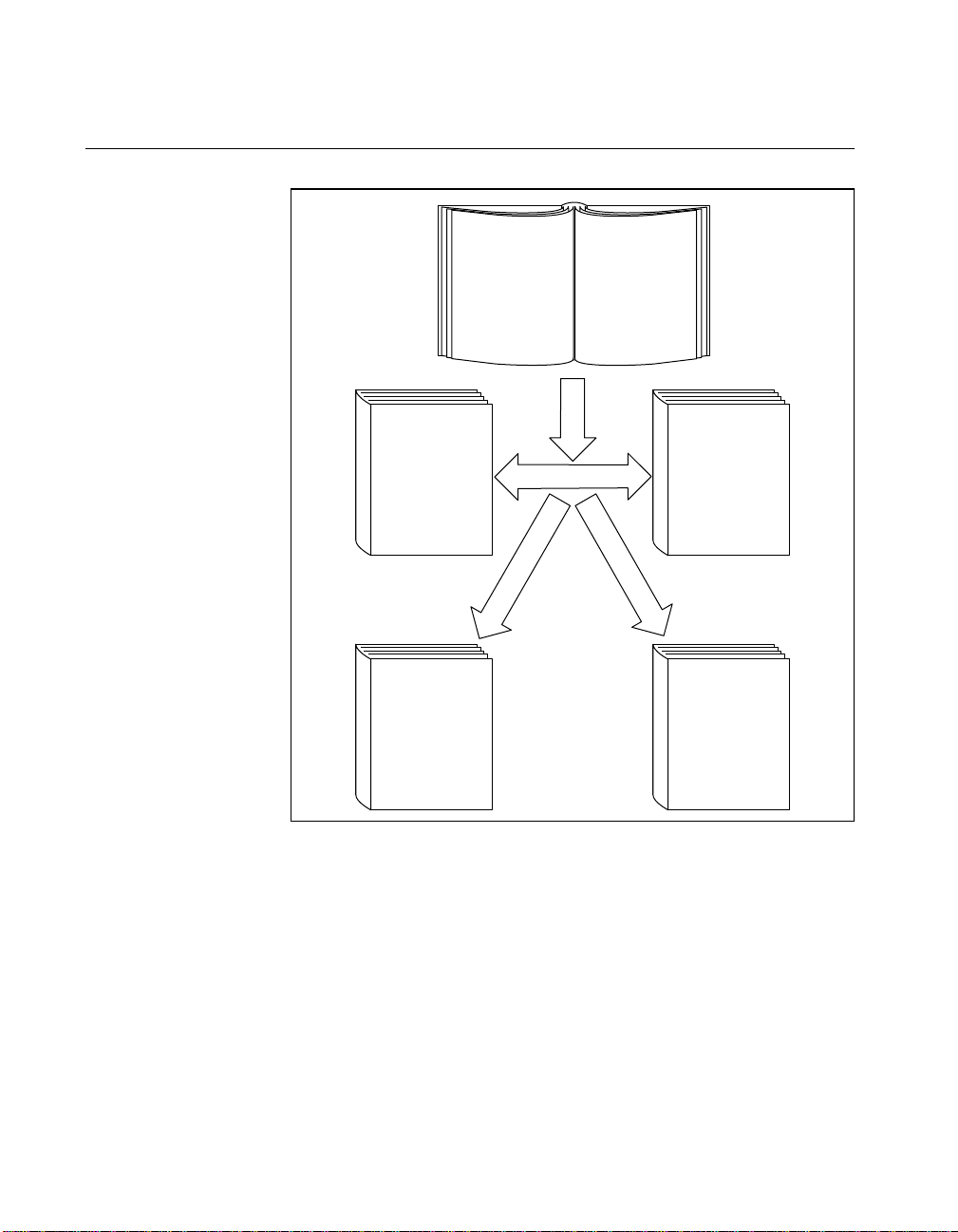
How to Use This Documentation Set
NI-VXI Programmer
Reference Manual
NI-VXI Function
Descriptions
Text
Based
NI-VXI Text Utilities
Reference Manual
VXITEDIT and
VICTEXT Descriptions
Getting Started
Manual
Installation and
Configuration
NI-VXI
User Manual
NI-VXI
Overview
Graphical
Based
NI-VXI Graphical
Utilities Reference
Manual
VXIEDIT and VIC
Descriptions
Begin by reading this getting started manual to guide you throu gh the
installation and configuration of the hardware and software. You should
install and configure the c ompon en ts of the V XI/VM E-PCI8 022 kit in
the order in which this manual describe s them. Be sure to rev iew the
Quick Start and Default Settings sections in Chapter 1. The material in
those sections may be all you need to get up and running with your
VXI/VME-PCI8022 kit.
When you are familiar with the material in this getting started manual,
you can begin to use the NI-VXI User Manual. This manual presents the
concepts of VXI an d p repa res y ou for d etaile d e xplana tions o f the
VXI/VME-PCI8022 for Solaris xiv
©
National Instruments Corporation
Page 15

NI-VXI functions. Study the descriptions of each function given in the
NI-VXI Programmer Reference Manual to fully understand the purpose
and syntax of eac h f unction.
Refer to the N I-VXI Graphical Utilities Reference Manual and the
NI-VXI Text Utilities R eference Manual to learn more about the NI-V XI
utilities.
Related Documentation
The following documents contain information that you may find helpful
as you read this manual:
• ANSI/IEEE Standard 10 14- 198 7, IEEE S tanda rd for a Versa tile
Backplane Bus: VMEbus
• ANSI/IEEE Standard 11 55- 199 3, IE EE VMEbus Ex tensions for
Instrumentation: VXIbus
• ANSI/VITA 1-1994 , VME 64
• Multisystem Extension Interface Bus Specification, Version 2.0,
National Instruments Corporation
• PCI Local Bus Specification, Revision 2.0, PCI Special Inte rest
Group
• VXI-MXI-2 User Manual, National Instruments Corporation
• VME-MXI-2 User Manu al , Na tional I nstru ments C orp oration
•VXI-6, VXIbus Mainframe Extender Specification, Rev. 1.0,
VXIbus Consortium
About This Manual
Customer Communication
National Instruments wants to rece ive you r com ments o n ou r prod ucts
and manuals. We are interested in the applications you develop with our
products, and we want to help if you have problems with them. To make
it easy for you to contact us, this manual contains comment and
configuration forms for you to complete. Thes e forms are in
Appendix E, Customer Communication, at the end of this manual.
©
National Instruments Corporation xv VXI/VME-PCI8022 for Solaris
Page 16

Chapter
Introduction and Quick Start
This chapter describes the VXI/VME- PCI8022 interface kits, lists what
you need to get started, introduces the concepts of MXI-2, and includes
a brief description of the hardware and softwa re.
This chapter also contains a Quick Start section, which has the basic
information you need to install the VXI/VME-P CI8022 interfa ce kit
with a simple config uration, al ong w ith a Default Settings section,
which lists the hardware and software default settings for easy
reference. Yo u may f ind th at thes e sec tions conta in a s m uc h
information as you n eed to g et star ted w ith y our VX I/VME -PC I8022
interface kit.
This manual uses the term VXI/VME-PCI8022 when information
applies to either the VXI-PCI8022 kit, which c ontains a VXI-M XI-2
module, or the VME-PCI8022 kit, w hich contains a VME -MXI-2
module. Similarly, the term VXI/VME-MXI-2 means that information
applies to either the VXI-MXI-2 or the VME-MXI-2.
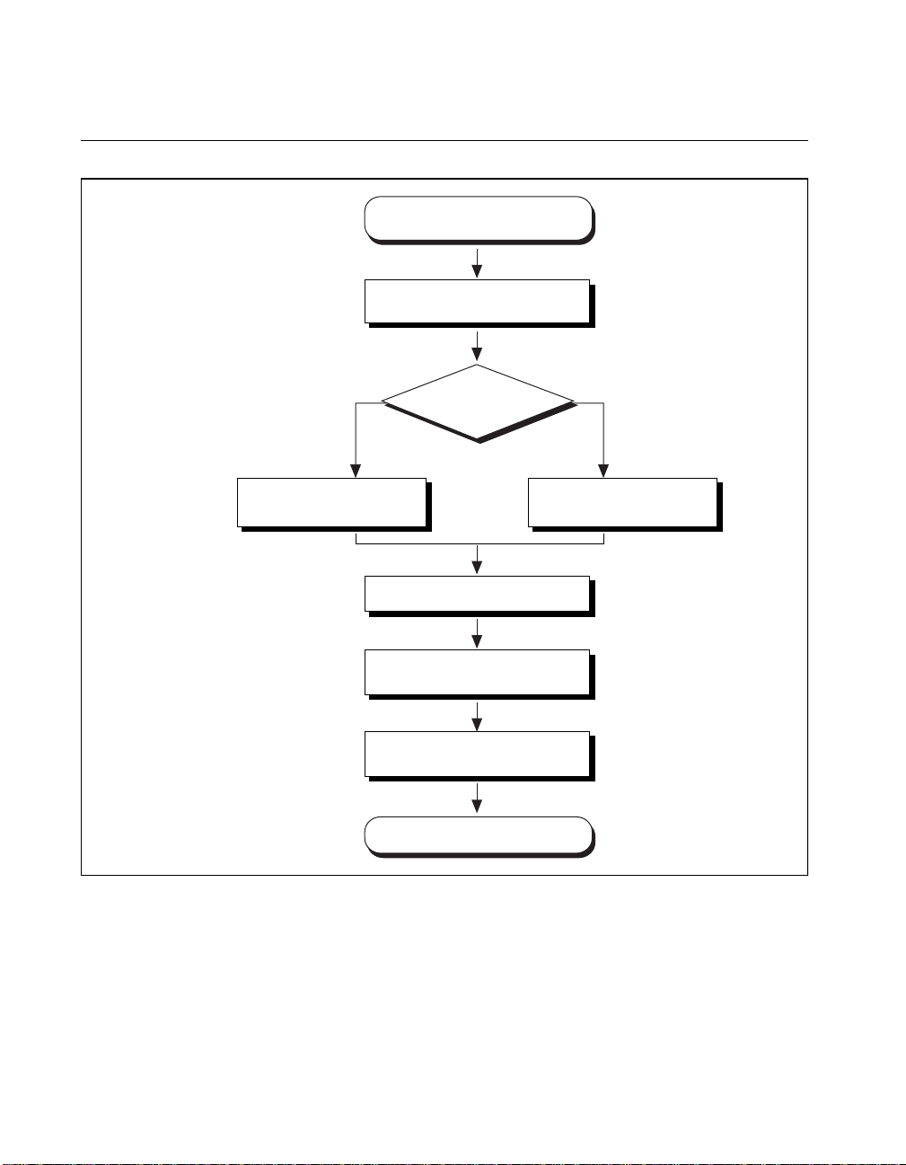
The following flowchart shows where to turn in this manual for more
details on configuring and using the hardware and software.
1
©
National Instruments Corporation 1-1 VXI/VME-PCI8022 for Solaris
Page 17
Chapter 1 Introduction and Quick Start
How to Use This Manual
Chapter 3
Chapter 1
Chapter 2
VXI VME
Configure and Install the
VXI-MXI-2
Chapter 5
Chapter 6
Install the NI-VXI Software
Gather What You Need
to Get Started
Configure and Install the
PCI-MXI-2
Using VXI or
VME?
Chapter 4
Run the Software
Configuration Utility
Configure and Install the
VME-MXI-2
Chapter 7
Software and
Utilities Reference
VXI/VME-PCI8022 for Solaris 1-2
Review Programming
Considerations
Write Application Program
©
National Instruments Corporation
Page 18

VXI/VME-PCI8022 Kit Overview
The VXI/VME-PCI8022 interface kits link any computer with a
PCI bus (hereafter referred to as a PCI-based computer) directly to the
VXIbus or VMEbus using the high-speed Mu ltisystem eXtension
Interface bus ( MXI -2).
A PCI-based computer e quipped wi th a VXI- PCI8 022 interf ace can
function as a VXI Commander and Resource Manager. A PCI-based
computer equipped w ith a VM E -PCI802 2 c a n fun ction a s a VM Eb us
master and/or slave devi ce. The V XI/VME -PCI802 2 makes your
PCI-based computer behave as though it were plugged directly into the
VXI/VME backplane as an embedded CPU VXI/VME module.
The software included with the kits is for Sparc-based computers.
What You Need to Get Started
❑ A PCI-based computer
❑ VXIbus or VMEbus mainframe
Chapter 1 Introduction and Quick Start
❑ PCI-MXI-2 interface board
❑ VXI-MXI-2 or VME-MXI-2 interface module
❑ MXI-2 cable
❑ NI-VXI software media for the PCI-MXI-2
MXI-2 Description
MXI-2 is the second g eneration of the Na tional I nstrume nts MX Ibu s
product line. The M XIbus is a gen eral- pur pose, 32-bit, mu ltimaster
system bus on a cab le. M XI-2 e xpand s the num be r of signa ls on a
standard MXI cable by including VX I triggers, all VX I interrupts,
CLK10, and all of the utility bus signals (SYSFAIL*, SYSRESET*,
and ACFAIL*).
Because MXI- 2 in co rpo ra tes al l o f th ese new signa ls in to a s in gl e
connector, the triggers, interrupts, and utility signals can be extended
not only to other mainframes but also to the local CPU in all MXI-2
©
National Instruments Corporation 1-3 VXI/VME-PCI8022 for Solaris
Page 19

Chapter 1 Introduction and Quick Start
products using a single cable. Thus, MXI-2 lets CPU interfac e boards
such as the PCI-MXI-2 perform as thou gh they were plugged direc tly
into the VXI/VME backplane.
In addition, MXI-2 boosts data thro ughp ut p erforma nce past p revious generation MXIbus produc ts b y d efini ng ne w high -perf orma nc e
protocols. MXI-2 is a superset of MXI. All accesses initiated by MXI
devices will work with MXI-2 devices. However, MXI-2 defines
synchronous MXI block data transfers which surpass previo us block
data throughput benchmarks. The new synchronous MXI block protocol
increases MXI-2 throu ghput to a maxim um of 3 3 MB/s between tw o
MXI-2 devices. All N ational Instruments MXI-2 boards are capable of
initiating and responding to synchronous MXI block cyc les.
Note: In the remainder of this manual, the term MXIbus refers to MXI-2.
Hardware Description
The PCI-MXI-2 is a half-size , PCI-compatible plug-in circuit board that
plugs into one of the expansion slots in your PCI-based computer . It
links your PCI-based co mp uter d irectly to the M XIb us a nd v ice ver sa.
Because the PCI-MXI-2 uses the same communication register set that
other VXIbus message-based de vices use, othe r MXIbus de vices view
the PCI-MXI-2 as a VXIbus devic e. The PCI- MXI -2 can also func tion
as the MXIbus System Contro ller and can term inate the MXIbus signa ls
directly on the PCI-MXI- 2. In addition , you can have up to 16 M B of
onboard DRAM on the PCI-MXI-2 that can be shared with the MXIbus
and VXI/VMEbus and used as a dedicated data buffer.
The VXI-MXI-2 m odu le is a n exte nded- class, re gister- based V XIbu s
device with optional VXIbus Slot 0 capability so that it can reside in any
slot in a C-size or D-size chassis.
Note: D-size VXI mainframes have connections for a P3 connector. The
VXI-MXI-2, however, does not have this connector and, if configured as a
Slot 0 controller, cannot p rovide the ne cessary control for VXI device s that
need P3 support.
The VXI-MXI-2 uses ad dress ma pping to convert MXIbus cycl es into
VXIbus cycles and vice versa. By connecting to the PCI-MXI-2 board,
the VXI-MXI-2 links the PCI bus to the VXIbus. The VXI-MXI-2 can
automatically determine whether it is located in VXI Slot 0 and/or if it
is the MXIbus System Controller.
VXI/VME-PCI8022 for Solaris 1-4
©
National Instruments Corporation
Page 20

Chapter 1 Introduction and Quick Start
The VME-MXI-2 m odu le is a single- slot, doub le- heig ht VM Ebus
device with optional VMEbus System Controller functions. It uses
address mapping to convert MXIbus c ycles into VM Ebus cycle s and
vice versa, just like the VXI-MXI-2. By connecting to the PCI-MXI-2
board, it links the PCI bus to the VMEbus. The VME-MXI-2 can
automatically determine if it is located in the first slot of a VMEbus
chassis and if it is the MXIbus System Controller.
Also, the VXI-MXI-2 and VME-MXI-2 automatically terminate the
MXIbus if installed as the first or last device in the MX Ibus. If installed
in the middle of the MXIbus, both the VXI-M XI- 2 and VME- MXI-2
automatically disable MXIbus termination. In addition, you can have up
to 64 MB of onboard DRAM on the VXI -MXI-2 and VME-M XI-2
modules that can either be shared with the VXI/VMEbus and MXIbus
or used as a dedicated data buffer.
The PCI-MXI -2, V X I-MX I -2, a nd V M E-MX I- 2 produc t s a chi ev e
high-performance blo ck transfer rates by integra tin g the MITE custom
ASIC, a sophisticated dual-channel DMA controller with standard
interfaces for V XI, VM E, M XI, a nd P CI. B y u si ng MITE DM A t o
transfer data and command s to and from devices, the MITE frees up a
computer’s microprocessor to perform other tasks such as data analysis
and presentation. In addition to DMA, the MITE incorporates both the
new Synchronous MXI pr otocol an d V ME6 4 M BL T (8 -by t e bloc k
transfers in which both the address bus and data bus a re used to transfer
data) directly into the ASIC to perform the fastest transfer operation to
instruments.
Software Description
The NI-VXI bus interfa ce softwa re for the PCI-MXI- 2 and Solaris 2. x
includes a Resource Manager, graphical and text-based versions of an
interactive VXI resour ce editor prog ra m, a com pre hensiv e libra ry of
software routines for V XI/VME p rog ramm ing, a nd grap hica l and
text-based versions of an interactive control program for interacting
with VXI/VME. You can use this software to seamlessly program
multiple-mainframe configurations and have software compatibility
across a variety of VX I/V ME con t rolle r p lat form s.
The NI-VXI software is a 32-bit driver de signed for Solaris 2. 5.1 or
higher compatible operating systems.
©
National Instruments Corporation 1-5 VXI/VME-PCI8022 for Solaris
Page 21

Chapter 1 Introduction and Quick Start
Optional Software
Your VXI/VME-PCI8022 kit includes the NI-V XI bus interface
software. In addition, y ou can use the Na tional I nstru ments L abV IEW
and LabWindows
ease your program ming ta sk. The se stan dardiz ed p rog rams ma tch the
modular virtual instrument capability of VXI and can reduce your VXI/
VMEbus software developme nt time. These programs ar e fully
VXIplug&play compliant and feature extensive libraries of VXI
instrument drivers written to take full advantage of direct VXI control.
LabVIEW is a complete programming en vironme nt that departs from
the sequential nature of traditional programming languages and features
a graphical programming env ironme nt.
LabWindows/CVI is an interactive C developmen t environment for
building test and measurement and instrum ent control sys tems. It
includes interactive code-generation tools and a graphical editor for
building custom user interfaces.
LabVIEW and LabWindows/CVI include all the tools needed for
instrument control, data acquisition, analysis, and presentatio n. When
you order the LabVIEW VXI Deve lopment System fo r Sun or the
LabWindows/CVI VXI Developm ent System for Sun, you also get
more than 500 complete instrument drivers, which are modular,
source-code program s that handle the commun ication with you r
instrument to speed your applic ation de velopm ent.
®
/CVI application programs and instrument drivers to
Quick Start
You can use this Quick Start section as a guide to q uickly con figur e
and operate your VXI or V ME system using the PCI-M XI- 2 a nd the
VXI-MXI-2 or VME-MXI-2.
The Quick Start summary assum es tha t y ou inten d to perf orm a basic
configuration as follows:
• You have one PCI-MXI-2 interface module, which you will install
in your PCI-based co mpu ter a s the Reso urc e M ana ger ( logic al
address 0).
• You have either one C-size VXI-MXI -2 or one 6U , B-size
VME-MXI-2, which you will install in a VXI or VME chassis,
respectively, and connect to the PCI-MXI-2.
VXI/VME-PCI8022 for Solaris 1-6
©
National Instruments Corporation
Page 22

• You will be using the NI-VXI software for initialization,
• You will use the default hardware and software settings.
Refer to the end of this chapter for a complete listing of the hardware
and software default settings. I f you ne ed m ore info rm ation, o r if y ou
want to try a different configuration, plea se refer to the ap propria te
hardware or softwa re chapt ers in thi s manua l, which descri be the
installation and configuration steps in greater detail.
Hardware Installation
To guard against electrostatic discharge, touch the antistatic plastic
package to a me tal p art of y our comp uter b ef ore remo ving the
PCI-MXI-2 from the package. Install the PCI-MXI-2 in an available
PCI slot in your PCI-based computer.
Chapter 1 Introduction and Quick Start
configuration, and device interac tion.
– The PCI-MXI-2 is the main contr oller, the VXI/VME Resource
Manager, and a m ess age - bas ed devic e.
– Your system contains only one VX I or VM E ch assis.
– There is no shar ed m emory u s ed on t he PC I-b ase d co mput er ,
the PCI-MXI-2, or the VXI/VME-MXI-2.
By default, the PCI-MXI-2 automatically detects whether it should be
the system controller on the MXIbus. Verify that the correct cable end
labeled Connect This End To D evic e Closest To MXIb us C ontroller I n
This Daisy Chain is attached securely to the PCI-MXI-2. The cable
must be connected in this manner so that the PCI-MXI-2 can correctly
detect whether it should be the system controller on the MXIbus. For
more information , refe r to Chap ter 2, PCI-MXI-2 Co nfiguratio n
and Installation.
You received either a VXI-M XI-2 or a VM E-MX I-2 in your VXI /
VME-PCI8022 kit. To guard a gainst e le ctrostatic disc harg e, touch the
antistatic plastic package to a metal part of your computer before
removing the VXI-MXI -2 or VME-MXI -2 from the pa ckage. Install the
VXI-MXI-2 in the first slot of a VXI chassis, or install the VME-MXI-2
in the first slot of a VME chassis.
The VXI/VME-MXI-2 default configuration automatically detects
whether it should be the VX I /VME bus system co ntroller. T he V XI/
VMEbus system controllers oper ate certain VX I/VMEbus lines as
required for VX I/V ME syste ms. Ve rif y tha t a ny oth er VX I/V ME
devices with system controller capability that are located in the same
©
National Instruments Corporation 1-7 VXI/VME-PCI8022 for Solaris
Page 23

Chapter 1 Introduction and Quick Start
chassis are not co nfigu red as s yste m cont rolle r. Hav ing mor e th an one
device configured as system controller will damage the VXI/VME
system.
For VXI sys tem s tha t in cl ud e V ME d ev ice s , en s ure th at th e V ME
devices are not configured in the upper 16 KB (starting from 0xC 000)
of the A16 address spac e. T his region is r eserv ed for V XI d evice
configuration registers, which are used for initializing, configuring, and
interacting with VXI devices. Th e PCI-M XI-2 and V ME-MX I-2 also
use this region for th is purpo se.
Also ensure that no V XI devic es in your sy stem are conf igured f or
either logical addresses 0 or 1. These are the default configurations for
the PCI-MXI-2 and the VXI-MXI-2, respectively.
For more details on the VXI-MXI-2 or VME-MXI-2 hardware, refer to
either Chapter 3, VXI-MXI-2 Configura tion a nd Installation, or
Chapter 4, VME-MXI-2 Configuration and Installation.
Installing and Loading the NI-VXI Software for Solaris 2.
The instructions in this section are specific to users of the Solaris 2.x
platform.
1. Type the following co mman d to c hange to a tempo ra ry direc tory :
cd /tmp
2. Type one of the following commands to copy and install script from
the NI-VXI diskette:
• If you are not running volume management:
tar xvf /dev/diskette INSTALL
• If you are running volume management:
tar xvf /vol/dev/rdiskette0/unlabeled INSTALL
Note: The device name shown in this code example may be different for your
system. Please refer to your system’s user guide or system administrator for
the correct device name. If it is different, modify the
reflect the correct device name.
3. Type the following command to execute the install script:
./INSTALL
Follow the instructions as prompted.
x
INSTALL script to
VXI/VME-PCI8022 for Solaris 1-8
©
National Instruments Corporation
Page 24

VME Users
Chapter 1 Introduction and Quick Start
4. Type the following command to remove the install script:
rm INSTALL
The NI-VXI driv er for Sol aris 2.x is added to the driver list
automatically during installation. It is loaded the first time you open the
driver (for example , ru nning
resman).
When used with a VXI-MXI-2, resman identifies and configures the
VXI devices, including the VXI-MXI-2. When used with a
VME-MXI-2,
PCI-MXI-2 to access devices in the VME chassis.
resman configures the V ME-MXI- 2 to allow the
resman does not
configure VME de vices. The VM E spec ifica tion does not s pec ify the
initialization and configuration procedures that the VXI specification
requires.
However, it is recommended that you enter the information about your
VME devices into the
vxiedit or vxitedit utility. resman can then
properly configure the various device-specific VME address spaces and
VME interrupt lines. For more information on configurin g non-VXI
devices in your VXI system, refer to the de scription of the Non-VXI
Device Configuration Editor in Chapter 3, VXI Resource Editor:
VXIedit, in the NI-VXI Graphical Utilities Reference Manual. For more
details about installing the NI- VXI software, r efer to Chapter 5, NI-VXI
Software Installation, in this manual.
Device Interaction
After resman has detected and configured all VXI /VM E de vice s, you
can view specific information on e ach device in your system by using
vxiedit or vxitedit utilities. These utilities include a Resource
the
Manager Display, which contains a description for each device,
including each VXI devic e’s lo gica l add ress.
You can interact with your VXI/VME devices by using the
victext utilities. These utilities let you interactively control your
VXI/VME devices without h avin g to use a co nvention al pr ogram min g
language, LabVIEW, o r La bWind ows/CV I.
Try the following in
vic or victext:
At the prompt, type:
help vxiinreg
©
National Instruments Corporation 1-9 VXI/VME-PCI8022 for Solaris
vic or
Page 25

Chapter 1 Introduction and Quick Start
This help file shows you the syntax for this command, which reads VXI
device configuration register s. The first argum ent is a logical add ress,
and the second is the o ffset of the VXI device configuration register to
be read.
Now type:
vxiinreg 1,0
This should return a value, such as:
Return Status (0): SUCCESS.
value = 0x4ff6
If the value ends with ff6, you have successfully read the National
Instruments manufactur er I D fr om the I D re giste r for the VX I/
VME-MXI-2.
You may now wan t to r ead th e configu ra tio n r egi sters fr om other VX I
devices in your system using the co mm an d
accesses only the upper 16 KB of A1 6 spa ce. Try r eading the register s
from one of the devices listed in the Resource Manager Display of
either
PCI-MXI-2 can access each of the devices in your VXI system
successfully.
vxiinreg. Thi s co mm and
vxiedit or vxitedit. In this way, you can verif y that your
You can also access V XI a n d V ME devices that are conf igu r ed in A1 6 ,
A24, and A32 address space by using the
For more informa tio n r egar ding
to the NI-VXI Graphical Utilities Reference Manual. For more
information rega rdin g
the NI-VXI Text Utilities Reference Manual.
Default Settings
This section summarizes the hardware and software default settings for
the VXI/VME-PCI8022 kit. If you need more information about a
particular setting, or if you want to try a different configuration, please
refer to the ap pro pria te ha rdwa re o r soft w are c hapt e rs in th is ma nua l.
The manual flowch ar t at the b egin ning of this ch ap ter dire c ts yo u to
where to find the inf orma tion y ou need .
VXI/VME-PCI8022 for Solaris 1-10
vxiin or vxiout commands.
vic operation and command s, refe r
victext operation and commands, ref er to
©
National Instruments Corporation
Page 26
PCI-MXI-2
Chapter 1 Introduction and Quick Start
This section summarizes the hardware and software default settings for
the PCI-MXI-2 .
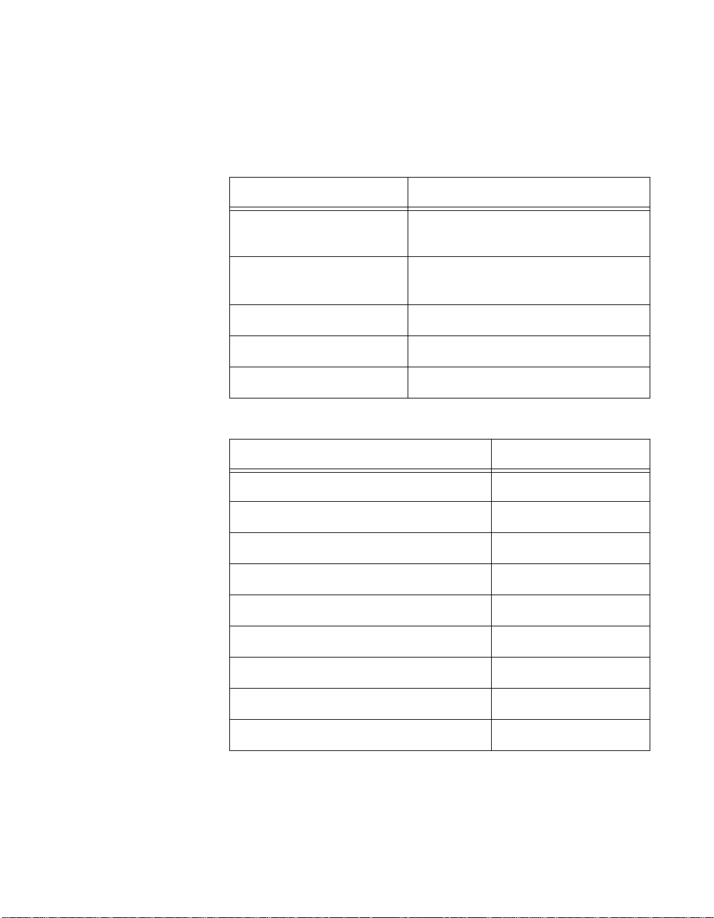
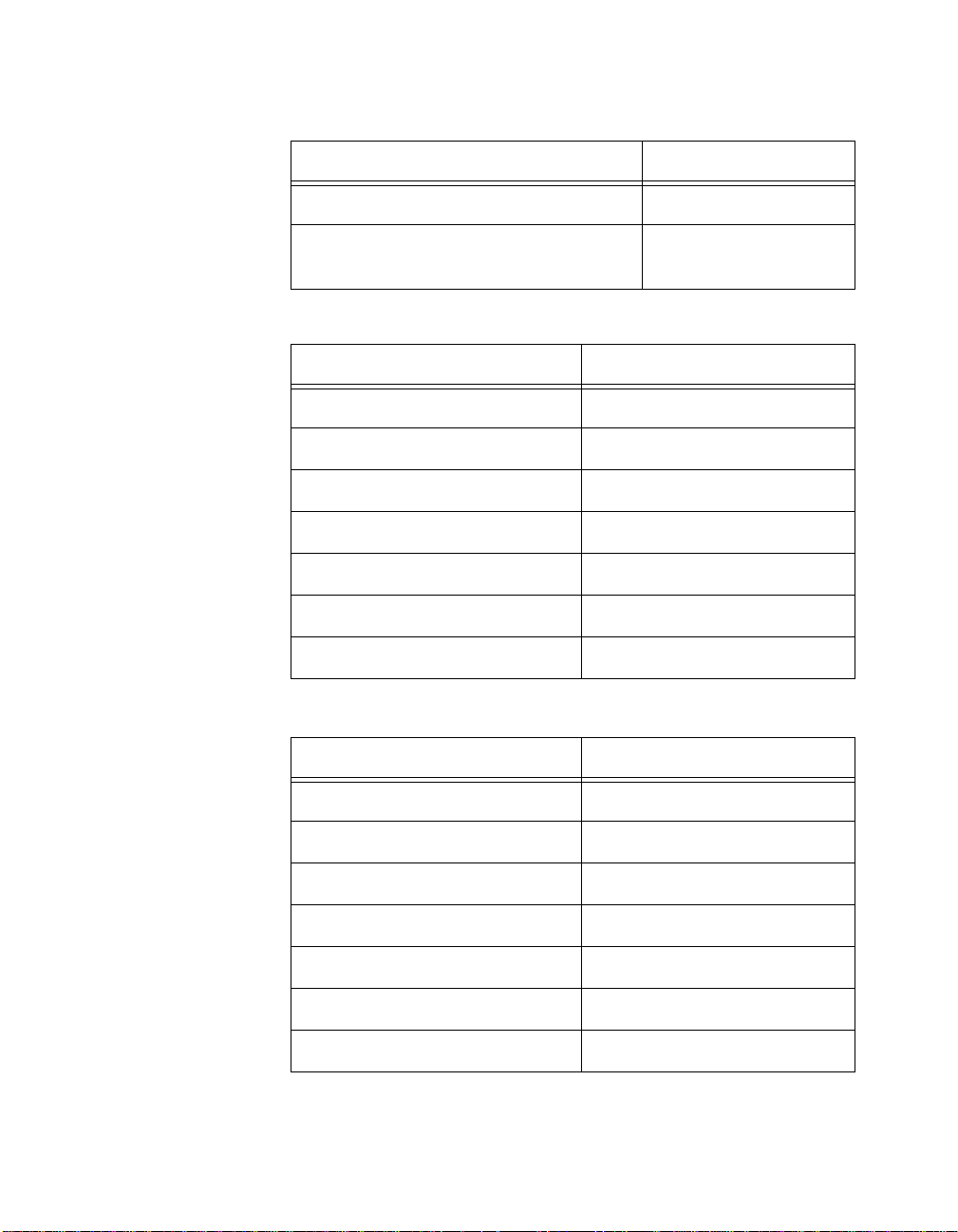
Table 1-1.
PCI-MXI-2 Hardware Default Settings
Hardware Component Default Setting
U17 Switch 1 (FOV) OFF: PCI-MXI-2 boots off the user-
configured half of the EEPROM.
U17 Switch 2 (TST) OFF: Factory configuration of the
EEPROM is protected.
U17 Switch 3 (POS) OFF: Do not alter this setting.
U17 Switch 4 (CT) ON: Do not alter this setting.
DRAM SIMM Installed Per customer order
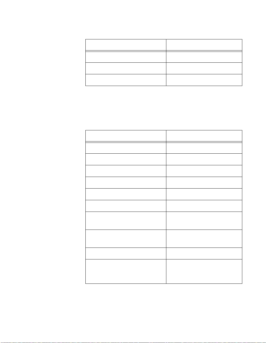
Table 1-2.
PCI-MXI-2 Logical Address Configuration Editor Default Settings
Editor Field Default Setting
Logical Address 0
Device Type MBD
Address Space A16
VXI Shared RAM Size 0 KB
Shared RAM Pool 0 KB
Lower Half Window Byte Swapping Disabled (non-swapped)
Lower Half Window Memory Select System Memory
Upper Half Window Byte Swapping Disabled (non-swapped)
Upper Half Window Memory Select System Memory
©
National Instruments Corporation 1-11 VXI/VME-PCI8022 for Solaris
Page 27
Chapter 1 Introduction and Quick Start
Table 1-2. PCI-MXI-2 Logical Address Configuration Editor Default Settings
Resource Manager Delay 5 s
Editor Field Default Setting
Map Upper/Lower Halves to Same
Disabled
Address
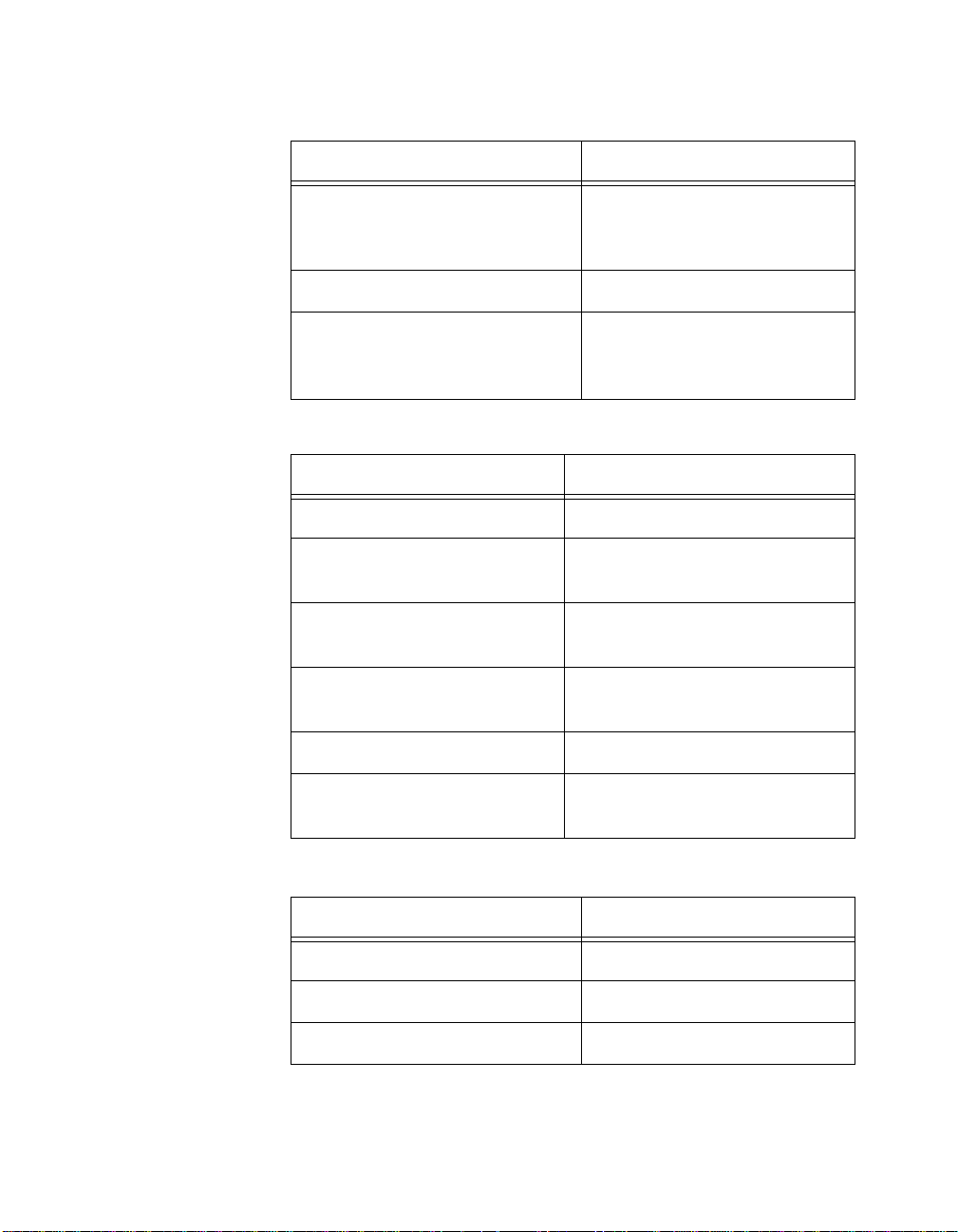
Table 1-3. PCI-MXI-2 Device Configuration Editor Default Settings
Editor Field Default Setting
Default Controller (LA-1) F irst Remote Controller
System IRQ Level 1
Servant Area Size 0
Number of Handlers 1
Number of Interrupters 0
Protocol Register 0xFF0
Read Protocol Re sponse 0x8448
Table 1-4. PCI-MXI-2 Bus Configuration Editor Default Settings
Editor Field Default Setting
MXI System Controller Auto
MXI Bus Timeout Valu e 1 ms
MXI CLK10 Receive
MXI Transfer Limi t Unlimited
VXImove uses Synchronous MXI Enabled
MXI-2 Auto Retry Enabled
A24/A32 Write Posting Disabled
VXI/VME-PCI8022 for Solaris 1-12
©
National Instruments Corporation
Page 28
Chapter 1 Introduction and Quick Start
VXI/VME-MXI-2
Table 1-4.
PCI-MXI-2 Bus Configuration Editor Default Settings (Continued)
Editor Field Default Setting
User Window Size 64 KB
Driver Window Size 32 KB
Expansion ROM Enabled
This section summarizes the hardware and software default settings for
the VXI-MXI-2 and VME-MXI-2.
Table 1-5.
VXI-MXI-2 Hardware Default Settings
Hardware Component Default Setting
Logical Address (U43) 1
VXIbus Slot 0/Non-Slot 0 (W2) Automatic detection
VXIbus Local Bus (S8, S9) Both OFF: Single VXI-MXI-2
VXIbus CLK10 Routing (W3) From onboard oscillator
External Trigger Termination (S2) OFF: Unterminated
SMB CLK10 Direction (S3) OUT: Drive CLK10 signal
SMB CLK10 Termination (S4) Ignored; effective only when S3
is set to IN.
Polarity of External SMB CLK10
Inverted
(S5)
MXIbus CLK10 Signal (S7) Receive CLK10 from MXIbus
MXIbus Termination
(U35 switches 1 and 2)
Automatic MXIbus termination:
switch 2 set to NO; switch 1
ignored.
©
National Instruments Corporation 1-13 VXI/VME-PCI8022 for Solaris
Page 29
Chapter 1 Introduction and Quick Start
Table 1-5. VXI-MXI-2 Hardware Default Settings (Continued)
Hardware Component Default Setting
Configuration EEPROM
(U35 switches 3 and 4)
User-modifiable; factory settings
protected: both switches set to
NO.
DRAM SIMMs Installed Per customer order
SIMM Size Configuration (S6) OFF if SIMMS are 4 M x 32
or larger; ON if smaller than
4 M x 32.
Table 1-6. VME-MXI-2 Hardware Default Settings
Hardware Component Default Setting
A16 Base Address (U20) Hex C040
VME-MXI-2 Intermodule
No user-defined pin selected
Signaling (W2)
MXIbus Termination
(U21 switches 3 and 4)
Configuration EEPROM
(U21 switches 1 and 2)
Automatic MXIbus termination:
switch 3 OFF; switch 4 ignored.
User-modifiable; factory settings
protected: both switches OFF.
DRAM SIMMs Installed Per customer order
SIMM Size Configuration (S2) OFF if SIMMS are 4 M x 32 or
Table 1-7. VXI/VME-MXI-2 Configuration Editor Default Settings
Editor Field Default Setting
Logical Address 1 (set by hardware switch)
LA Selection Set by hardware switch
Address Space A24 *
VXI/VME-PCI8022 for Solaris 1-14
larger; ON if smaller than 4 M x 32.
©
National Instruments Corporation
Page 30

Chapter 1 Introduction and Quick Start
Table 1-7. VXI/VME-MXI-2 Configuration Editor Default Settings (Continued)
Editor Field Default Setting
Requested Memory 16 KB *
A16 Write Posting Disabled
A24/A32 Write Posting Disabled
Interlocked Mode Disabled
VXI/VME System Controller Auto
VXI/VME Bus Timeout Value 125 µs
VXI/VME Auto Retry Disabled
VXI/VME Trans fe r Li mi t 256
VXI/VME Arbite r Typ e Priority
VXI/VME Reque s t Lev e l 3
VXI/VME Fair Reques t Enabled
VXI/VME Arbite r Ti me o u t Enabled
MXI System Controller Auto
MXI Bus Timeout Valu e 1 ms
MXI Auto Retry Disabled
MXI Transfer Limi t Unlimited
MXI Parity Checking Enabled
MXI Fair Requester Disabled
MXI CLK10 Set by hardware switch
(VXI-MXI-2 only)
* Assumes no DRAM is installed. If DRAM is installed, the Address
Space would be A32, and Requested Memory would match the
amount of DRAM.
©
National Instruments Corporation 1-15 VXI/VME-PCI8022 for Solaris
Page 31

PCI-MXI-2 Configuration
Chapter
and Installation
This chapter contains the instructions to configure and install the
PCI-MXI-2 module.
Caution:
!
Configure the PCI-MXI-2
Electrostatic d isc h arg e c an d a ma ge s eve r a l co mp on ent s on yo u r
PCI-MXI-2 module. To avoid suc h damag e in hand ling the m odule,
touch t he antistatic plastic pa ckage to a metal part o f your comp uter
chassis before removing the PCI-MXI-2 from the package.
This section describes h ow to conf igure the fo llowin g options on the
PCI-MXI-2.
• Configuration EEPROM
• Onboard DRAM
Figure 2-1 shows the PCI-MXI-2. The dr awing shows the location and
factory-default settings on the mo dule.
2
©
National Instruments Corporation 2-1 VXI/VME-PCI8022 for Solaris
Page 32

Chapter 2 PCI-MXI-2 Configuration and Installation
1
1U17 2 DRAM
Figure 2-1. PCI-MXI-2 Parts Locator Diagram
VXI/VME-PCI8022 for Solaris 2-2
2
©
National Instruments Corporation
Page 33

Configuration EEPROM
The PCI-MXI-2 has an onboard EEPROM, which stores default register
values that are loaded at power-on. The EEPROM is divided into two
halves—a factory-configuration half, and a user-configuration half—so
you can modify the user-configurable half, while the factory-configured
half stores a back-up of the def ault use r settings. T he f actor y
configuration is a min imal conf iguration tha t allows yo u to boot y our
PCI-MXI-2 regardless of the change s made to the user conf iguration.
For information on configuring the onb oard EEPRO M, refe r to
Appendix C, EEPROM Configuration.
Onboard DRAM
The PCI-MXI -2 ca n a ccom mod at e o ne D RAM S IMM . Ta ble 2 -1 l is ts
the SIMMS you can use. You can use 32-b it or 36-bit SIMMS sinc e
DRAM parity is not required. The PCI-MXI-2 can hold up to 16 MB of
onboard memory. T he PC I-M XI- 2 supports DR AM speed s of 8 0 n s o r
faster. The ma ximu m s ize f or th e D RA M SI MM s is 1 i n.
Chapter 2 PCI-MXI-2 Configuration and Installation
Table 2-1.
SIMMs Total DRAM National Inst rum e n ts
— 0 —
256K x 32 or
256K x 36
1M x 32 or
1M x 36
4M x 32 or
4M x 36
PCI-MXI-2 DRAM Configurations
Option?
1 MB —
4 MB YES
16 MB YES
©
National Instruments Corporation 2-3 VXI/VME-PCI8022 for Solaris
Page 34

Chapter 2 PCI-MXI-2 Configuration and Installation
Install the PCI-MXI-2
This section contains general installation instructions for the
PCI-MXI-2. Consult your computer user manual or technical reference
manual for specific instru ction s and war nings.
1. Plug in your PCI-based computer before installing the PCI-MXI-2.
The power cord grounds the co mputer and pr otects it from
electrical damage while you are installing the module.
Warning: To protect both yourself and the computer from electrical hazards, the
computer should remain off until you are finished installing the
PCI-MXI-2 module.
2. Remove the top cove r or a ccess p ort to the PC I bus.
3. Select any availab le PCI ex pansion slot.
4. Touch the metal part of the power supply case inside the computer
to discharge any static electricity that might be on your clothes or
body.
5. Line up the PCI-MXI-2 with the MXI-2 connector near the cut-out
on the back panel. Slowly push down on the top of the PCI-MXI-2
until its card-edge connector is resting on the expansion slot
receptacle. Using slow, evenly distributed pressure, press the
PCI-MXI-2 straight down until it seats in the expansion slot.
6. Check the installation. Ensure that the PCI-MXI-2 is secure in its
slot.
7. Replace the computer cover.
VXI/VME-PCI8022 for Solaris 2-4
©
National Instruments Corporation
Page 35

Figure 2-2 shows h ow to install the PCI-MXI-2.
MXI-2 Connector
PCI Bus
Card-Edge Connector
Cut-outs
PCI Bus Slot
Chapter 2 PCI-MXI-2 Configuration and Installation
PCI-MXI-2 Board
Figure 2-2. PCI-MXI-2 Installed in a Computer
©
National Instruments Corporation 2-5 VXI/VME-PCI8022 for Solaris
Page 36

VXI-MXI-2 Configuration
Chapter
and Installation
This chapter contains the instructions to configure and install the
VXI-MXI-2 module. This chapte r applies only if you orde red the
VXI-PCI8022 interface kit. If you ordered the VM E-PCI8022 kit, skip
this chapter and refer to Chapter 4, VME-MXI-2 Con figuration and
Installation.
Caution:
!
Configure the VXI-MXI-2
Electrostatic d isc h arg e c an d a ma ge s eve r a l co mp on ent s on yo u r
VXI-MXI-2 module. To avoid such damage in handling the mo dule,
touch t he antistatic plastic pa ckage to a metal part o f your VXI chassis
before removing the VXI-M XI-2 f rom the pa ck age.
This section describes h ow to conf igure the fo llowin g options on the
VXI-MXI-2.
• VXIbus logical address
• VXIbus Slot 0/Non-Slot 0
• VXIbus local bus
• VXIbus CLK10 routing
• Trigger input termination
• MXIbus termination
• Configuration EEPROM
• Onboard DRAM
3
Figure 3-1 shows the VXI-MXI-2 as it would appear when facing the
right side cover. The drawing shows the location and factory-defa ult
settings of most of the configuration switches and jumpers on the
module. Notice that switch S6 (called out as numbe r 8 in the figure)
is a ccessible on ly by rem ovin g the fro nt cov er.
©
National Instruments Corporation 3-1 VXI/VME-PCI8022 for Solaris
Page 37

Chapter 3 VXI-MXI-2 Configuration and Installation
Nonslot 0
Auto
2
1
Slot 0
W2
No
Yes
1
No
Yes
Yes
432
U35
Terminate MXIbus
Automatic MXIbus Termination Yes
No
No
Change Factory Configuration
Restore Factory Configuration
3 4 5
S8
S9
W3
CLK10
Source
From MXIbus
From onboard oscillator
From SMB (S3 must be set to "IN")
YesNo
VXI-MXI to left
VXI-MXI to right
Routing
MXI CLK10
Turn off power to instruments and cables
before installing or removing any modules.
WARNING:
SWITCH
Shown at default
Address 1
setting of Logical
LOGICAL ADDRESS
Receive CLK10 from MXIbus
S7
Drive CLK10 out MXIbus
87
654
U43
3
21
Push up for logic 1
Push down for logic 0
6
7
8
(All switches and jumpers shown in default position)
VXI-MXI-2
1 U35
2W2
3W3
4S8
5S9
6S7
Figure 3-1. VXI-MXI-2 Right-Side Cover
VXI/VME-PCI8022 for Solaris 3-2
7 U43
8S6
9S5
INVERTED
NON-INVERTED
SMB CLK10 Output Polarity (Effective only when S3 is set to "OUT")
50 Termination for SMB CLK10 (Effective only when S3 is set to "IN")
On
In
SMB CLK10 Direction
On
50 Termination for External Trigger Input
9
S5
10
S4 Off
S3
Out
11
S2 Off
12
10 S4
11 S3
12 S2
©
National Instruments Corporation
Page 38

Front Panel Features
The VXI-MXI-2 has the following front panel features.
• Three front panel LEDs
– SYSFAIL LED indicates that the VMEbus SYSFAIL line is
asserted.
– MXI LED indicates when the VXI-MXI-2 is accessed fr om the
MXIbus.
– VXI LED indicates when the VXI-MXI-2 is accessed f rom t he
VXIbus.
• MXIbus connector
• Three SMB connectors
– External clock
– Tr igger outpu t
– Tr igger input
• System reset push-button
Removing the Metal Enclosure
The VXI-MXI-2 is housed in a metal enclosure to improve EMC
performance and to provide ea sy ha ndling. B eca use the enc losur e
includes cutouts to facilitate changes to the switch and jumper settings,
it should not be necessary to remove it under normal circumstances.
Chapter 3 VXI-MXI-2 Configuration and Installation
However, it is necessary to remove the enclosure if you want to change
the amount of DRAM installed on the VXI-MXI-2. Switch S6, which is
directly related to the amount of DRAM you want to install, is also
accessible only by removing the enclosure. If you will be making this
change, remov e the f our scre ws on the top, the four sc rew s o n the
bottom, and the five scr ews on the right side cov er o f th e enclosu re .
Refer to the O n boar d DR AM section later in this chapter for details
about changing DRAM.
©
National Instruments Corporation 3-3 VXI/VME-PCI8022 for Solaris
Page 39

Chapter 3 VXI-MXI-2 Configuration and Installation
VXIbus Logical Address
Each device in a VXIbus /MXIb us system is a ssigned a uniq ue n umber
between 0 and 25 4. Th is 8- bit n umber , called the logica l address,
defines the base address fo r the VXI configuration registers located on
the device. With un ique log ical addr es ses, e ach VX Ibu s devic e in the
system is assigned 64 bytes of conf igura tion space in th e upper 16 KB
of A16 space.
Logical address 0 is reserved fo r the Resourc e Manage r in the VX Ibus
system. Because the VXI -MXI- 2 ca nno t act as a Reso urce Manager , do
not configure the VXI-MXI-2 with a logical address of 0.
Some VXIbus devices have dynamically configu rable logical
addresses. These devices have an initial logical address of hex FF or
255, which indicates that they can be dynamically configured. While
the VXI-MXI-2 does su ppo rt dyna mic c onfigur ation of VX I de vices
within its mainframe, it is itself a statically configured device and is
preset at the factory with a VXI logical address of 1.
Ensure that no other statically configurable VXIbus devices have a
logical address of 1. If they do, change the logical address setting of
either the VXI-MXI-2 or the other device so that every device in the
system has a unique associated logical address.
You can change the logical address of the VXI-MXI-2 by changing the
setting of the 8-bit DIP switch labeled LOGICAL ADDR ES S SWITC H
(location designator U43) on the panel. Th e down positio n of the DIP
switch corresponds to a logic value of 0 and the up position corresponds
to a logic value of 1. Verify that the VX I-MXI-2 doe s not have the same
logical address as any other statically configured VXIbus device in your
system. Remember that logical addre sses hex 0 and FF are not all owed
for the VXI-MXI-2. Also, when setting logical addre sses, keep in mind
the grouping requiremen ts set by the system hiera rchy. See VXI-6,
VXIbus Mainframe Extender Specification, for more information on
setting logical addresses on a multimainframe hierarchy.
VXI/VME-PCI8022 for Solaris 3-4
©
National Instruments Corporation
Page 40

Chapter 3 VXI-MXI-2 Configuration and Installation
Figure 3-2 shows switch settings for log ical addr ess he x 1 and C0 .
LOGICAL ADDRESS
SWITCH
Shown at default
setting of Logical
Address 1
Push up for logic 1
Push down for logic 0
12345678
U43
a. Switch Set to Logical Address 1 (Default)
LOGICAL ADDRESS
SWITCH
Shown at default
setting of Logical
Address 1
Push up for logic 1
Push down for logic 0
12345678
U43
b. Switch Set to Logical Address Hex C0
Figure 3-2. Logical Address Selection
VXIbus Slot 0/Non-Slot 0
The VXI-MXI-2 is configured at the factory to automatically detect if
it is installed in Slot 0 of a VXIbus mainframe. With automatic Slot 0
detection, you can install the VXI-MX I-2 into any VXI bus slot.
You can manually configure the VXI- MXI-2 for either Slot 0 or NonSlot 0 operation by defeating the automatic-detection circuitry. Use the
three-position jumper W2 to select automatic Slot 0 detection, Slot 0, or
Non-Slot 0 operation. Figure 3-3 shows these three settings.
©
National Instruments Corporation 3-5 VXI/VME-PCI8022 for Solaris
Page 41

Chapter 3 VXI-MXI-2 Configuration and Installation
Caution: Do not install a device configured for Slot 0 into another slot without
!
first reconfiguring it to either Non-Slot 0 or autom atic configuration.
Neglecting to do this could damage the device, the VXIbus backplane, or
both.
W2
Slot 0
Auto
Nonslot 0
a. Automatic Slot 0 Detection (Default)
W2
Slot 0
Auto
Nonslot 0
b. Manual Slot 0 Configuration
c. Manual Nonslot 0 Configuration
Figure 3-3. VXIbus Slot Configuration
When the VXI-MXI-2 is installed in Slot 0, it becomes the VMEbus
System Controller. In this role, it has VMEbus Data Transfer Bus
Arbiter circuitry that accepts bus requests on all four VMEbus request
levels, prioritizes the requests, and grants the bus to the highest priority
requester. As VMEb us System Contro ller, th e VX I -MXI-2 a lso d rives
the 16 MHz VMEbus system clock by an onb oard 16 MHz osc illator.
VXI/VME-PCI8022 for Solaris 3-6
Slot 0
Auto
Nonslot 0
W2
©
National Instruments Corporation
Page 42

VXIbus Local Bus
Chapter 3 VXI-MXI-2 Configuration and Installation
As required by the VXIbus specification, the VXI-MXI-2 drives the
10 MHz signal CLK10 on a differential ECL output wh en installed in
Slot 0. W hen not installed in Slot 0, the VXI-MXI-2 only receives the
CLK10 signal.
If you will be installing more than one VXI-MXI-2 in a single VXIbus
mainframe, you must configure the boards to use the loc al bus. The
VXI-MXI-2 uses the local bus to pass a signal to the other VXI-MXI-2
modules in the mainframe to disable the VMEbus bus timeout unit
(BTO) during cycles that map to the MXIbus. Because the local bus is
used, you need to install all VXI-MXI-2 modules for a single mainframe
in adjacent slots.
You will use two switches on the VXI-MXI-2 to select its position in
relation to any other VXI-MXI-2 module in the ma infram e. Use sw itch
S9 when there is a VXI-MXI-2 to the right (higher numbered slot). Use
S8 when there is a VXI-MXI-2 to the left (lower numbered slot).
Figure 3-4 shows four configuration settings f or a VX I-MXI- 2.
Figure 3-4a illustrates the default setting, which is for a single
VXI-MXI-2 in a mainframe. Use the setting in Figure 3-4b for the
VXI-MXI-2 located to the lef t of all others . Figure 3-4c show s the
setting to use if the VXI-MXI-2 is between two others. Use the setting
of Figure 3-4d for the VXI-MXI-2 located to the right of all othe rs.
©
National Instruments Corporation 3-7 VXI/VME-PCI8022 for Solaris
Page 43

Chapter 3 VXI-MXI-2 Configuration and Installation
VXI-MXI to left
No Yes
VXI-MXI to right
a. Single VXI-MXI-2 in Mainframe (Default)
No Yes
VXI-MXI to left
VXI-MXI to right
c.VXI-MXI-2 between Two Others
VXIbus CLK10 Routing
When the VXI-MXI-2 is installed in Slot 0 of your mainframe, it
supplies the VXIbus CLK10 signa l. The VX I-MX I-2 can us e three
different sources to generate this signal: an onb oard oscillator, the
external CLK SMB connector, and the MXIbus CLK10 signal. Use
the three-position jumper W3 to select these options, as shown in
Figure 3-5.
S8
S9
VXI-MXI to left
VXI-MXI to right
b. Leftmost VXI-MXI-2 in Mainframe
S8
S9
VXI-MXI to left
VXI-MXI to right
d. Rightmost VXI-MXI-2 in Mainframe
Figure 3-4. VXIbus Local Bus Configuration
S8
S9
No Yes
S8
S9
No Yes
Notice that Figure 3-5b and Figure 3-5c also show switches S3 and S7,
respectively. You must configure these switches as shown w hen using
the corresponding CLK 10 so urce settin g of W3.
VXI/VME-PCI8022 for Solaris 3-8
©
National Instruments Corporation
Page 44

Chapter 3 VXI-MXI-2 Configuration and Installation
In
S3 Out
From onboard oscillator
From SMB (S3 must be set to "IN")
From MXIbus
W3
a. CLK10 Generated from Onboard Oscillator (Default)
From onboard oscillator
From SMB (S3 must be set to "IN")SMB CLK10 Direction
From MXIbus
b. CLK10 Generated from SMB
From onboard oscillator
From SMB (S3 must be set to "IN")
From MXIbusReceive CLK10 from MXIbus
W3
W3
S7
c. CLK10 Generated from MXIbus
Figure 3-5. VXIbus CLK10 Routing
©
National Instruments Corporation 3-9 VXI/VME-PCI8022 for Solaris
Page 45

Chapter 3 VXI-MXI-2 Configuration and Installation
The VXI-MXI-2 can also be configured to drive the exter nal CLK SMB
signal from the VXIbus CLK10 signal. Switch S3 controls whether the
VXI-MXI-2 drives or receives the external CLK SMB signal. If you
change the S3 setting to drive CLK 10 out the e xterna l CLK 10 SMB
connector, do not set the W3 jumper to receive the SMB CLK10 signal;
instead use the settings sho wn in either Figure 3-5a or Figu re 3-5c as
appropriate.
When switch S3 is set so that the VXI-MXI-2 receives the SMB CLK10
signal, you have the option to add a 50 is unused—its setting does not
matter—when S3 is configured to drive the external CLK SMB signal.
You can use an additional switch, S5, to control the polarity of the
external CLK SMB signal when S3 is configured to drive it. S5 is
unused—its setting does not matte r—when S3 is configured to receive
the external CLK SMB signal.
Figure 3-6 shows four configuration settings f or the VX I-MXI -2.
Figure 3-6 a shows the default configuration, which is for driving the
inverted external CLK SMB. Use the settings of Figure 3-6b to drive the
noninverted external CLK SMB signal. Figure 3-6c illustrates the
setting for receiving the external CLK SMB signal. Finally, you can
configure the switches as shown in Figure 3-6d to receive the external
CLK SMB signal with a 50 Ω termination.
Note: The settings of any switches shown with this pattern ( ) have no bearing
on the configuration described in any of the following figures.
VXI/VME-PCI8022 for Solaris 3-10
©
National Instruments Corporation
Page 46

Chapter 3 VXI-MXI-2 Configuration and Installation
S2 Off
S3 Out
S4 Off
S5
S2 Off
S3 Out
S4 Off
S5
S2 Off
S3 Out
S4 Off
S5
On 50 Ω Termination for External Trigger Input
In
SMB CLK10 Direction
50 Ω Termination for SMB CLK10 (Effective only when S3 is set to "IN")
On
SMB CLK10 Output Polarity (Effective only when S3 is set to "OUT")
NON-INVERTED
INVERTED
a. Drive Inverted External CLK SMB (Default)
On 50 Ω Termination for External Trigger Input
In
SMB CLK10 Direction
50 Ω Termination for SMB CLK10 (Effective only when S3 is set to "IN")
On
SMB CLK10 Output Polarity (Effective only when S3 is set to "OUT")
NON-INVERTED
INVERTED
b. Drive Non-Inverted External CLK SMB
On 50 Ω Termination for External Trigger Input
In
SMB CLK10 Direction
50 Ω Termination for SMB CLK10 (Effective only when S3 is set to "IN")
On
SMB CLK10 Output Polarity (Effective only when S3 is set to "OUT")
NON-INVERTED
INVERTED
c. Receive External CLK SMB
S2 Off
S3 Out
S4 Off
S5
On 50 Ω Termination for External Trigger Input
In
SMB CLK10 Direction
50 Ω Termination for SMB CLK10 (Effective only when S3 is set to "IN")
On
SMB CLK10 Output Polarity (Effective only when S3 is set to "OUT")
NON-INVERTED
INVERTED
d. Receive External CLK SMB with 50 Ω Termination
Figure 3-6. SMB CLK10 Settings
©
National Instruments Corporation 3-11 VXI/VME-PCI8022 for Solaris
Page 47

Chapter 3 VXI-MXI-2 Configuration and Installation
a
The VXI-MXI-2 can also drive or receive the MXIbus CLK10 signal.
Switch S7 controls whether the VXI-MXI -2 drives MXI bus CLK10
from the VXIbus CLK10 or receives MXIbus CLK10. As shown earlier
in Figure 3-5c, if W3 is configur ed to use the MX Ib us CLK 10 to
generate the VXIbus CLK10 signal, sw itch S7 must be configur ed to
receive MXIbus CLK 10 . This is sh own aga in in Figu re 3-7a b elow. I f
you change the S7 setting to drive CLK 10 ou t the M XIb us, do not set
the W3 jumper to receive the MXIbus CLK10; instead use the settings
shown in Figure 3-5a or Figure 3-5b as appropriate.
Caution: Do not configure more than one MXIbus device to drive the MXIbus
!
CLK10. Having a second device driving MXIbus CLK10 could damage the
device.
Figure 3-7 shows the configuration settings for rece iving an d driving
MXIbus CLK10, respec tively.
Drive CLK10 out MXIbus
S7
Receive CLK10 from MXIbus
. Receive CLK10 from MXIbus (Default) b. Drive MXIbus CLK10 from VXIbus CLK10
Figure 3-7. Receiving or Driving MXIbus CLK10
S7
Drive CLK10 out MXIbus
Receive CLK10 from MXIbus
Trigger Input Termination
You can use switch S2 to terminate the external trigger input SMB with
50 Ω. Figure 3-8a shows the default setting for a nonterminated trigger
input SMB. Use the setting of Figure 3-8b to terminate the trigger input
SMB. Switch S2 is located above switches S3, S4, and S5, which have
no effect on this configuration.
©
VXI/VME-PCI8022 for Solaris 3-12
National Instruments Corporation
Page 48

Chapter 3 VXI-MXI-2 Configuration and Installation
S2 Off
S3 Out
S4 Off
S5
S2 Off
S3 Out
S4 Off
S5
On 50 Ω Termination for External Trigger Input
In
SMB CLK10 Direction
50 Ω Termination for SMB CLK10 (Effective only when S3 is set to "IN")
On
SMB CLK10 Output Polarity (Effective only when S3 is set to "OUT")
NON-INVERTED
INVERTED
a. Non-Terminated External Trigger Input SMB (Default)
On 50 Ω Termination for External Trigger Input
In
SMB CLK10 Direction
50 Ω Termination for SMB CLK10 (Effective only when S3 is set to "IN")
On
SMB CLK10 Output Polarity (Effective only when S3 is set to "OUT")
NON-INVERTED
INVERTED
b. Terminated External Trigger Input SMB with 50 Ω
Figure 3-8. SMB Trigger Input Termination
MXIbus Termination
The first and last MXIbus device s conn ec ted to the MX Ibu s—w hether
it is a single MXI-2 cable or daisy-chained MXI- 2 cables— must
terminate the MXIbus. Any MXIbus devices in th e middle o f a MXIbus
daisy chain must not terminate the MXIbus.
The VXI-MXI-2 automatically senses whether it is at either end of the
MXIbus cable to terminate the MXIbus. You ca n manu ally control
MXIbus termination by defeating the automatic circuitry. Use
switches 1 and 2 of the four-position switch at loc ation U35 to contro l
whether MXIbus termination is automatic (Figure 3-9a), on
(Figure 3-9b), or off (Figure 3-9c). The settings o f switche s 3 a nd 4
have no effect o n M XIb us te rm inatio n.
©
National Instruments Corporation 3-13 VXI/VME-PCI8022 for Solaris
Page 49

Chapter 3 VXI-MXI-2 Configuration and Installation
Use switch 2 of U35 to select whether you want the VXI-MXI -2 to
automatically control termination of the MXIbus. Switch 1 of U35 le ts
you manually control whether to terminate the MXIbus when automatic
termination is turned off. Switch 1 ha s no effect when switch 2 is set for
automatic MXIbus termination; you must turn off automatic
termination if you want to manually control termination.
Restore Factory Configuration
Change Factory Configuration
Automatic MXIbus Termination
a. Automatic MXIbus Termination (Default)
Restore Factory Configuration
Change Factory Configuration
Automatic MXIbus Termination
Terminate MXIbus
Terminate MXIbus
No
No
Yes
Yes
No
No
Yes
Yes
U35
U35
Yes
Yes
No
1234
No
Yes
Yes
No
1234
No
b. Terminate MXIbus (On)
Restore Factory Configuration
Change Factory Configuration
Automatic MXIbus Termination
Terminate MXIbus
c. Do Not Terminate MXIbus (Off)
Figure 3-9. MXIbus Termination
VXI/VME-PCI8022 for Solaris 3-14
U35
No
No
Yes
Yes
©
National Instruments Corporation
Yes
Yes
No
1234
No
Page 50

Configuration EEPROM
The VXI-MXI-2 h as an o nboa rd E EPR OM, whic h s tore s d efau lt
register val ue s th at ar e loa de d a t p ower -o n . Th e EE PR OM i s di vide d
into two halves—a factory-configuration half, and a user-configuration
half. Both halves were factory configured with the same configuration
values so you ca n modify the user-configurable half, wh ile the factoryconfigured half stores a back-up of the default user settings.
Use switches 3 and 4 of the four -po sition switch at loca tion U3 5 to
control the operation of th e EEPRO M. The R esto re Fa ctor y
Configuration switch (switch 4) causes the VXI-MXI-2 to boot off the
factory-configured half instead of the user-modified settings. This is
useful in the event that the user-configur ed half of the EEPROM
becomes corrupted in such a way that the VX I-MXI-2 boo ts to an
unusable state.
The Change Factory Config uration switch (sw itch 3 of U35) lets you
change the factor y-def au lt co nfig uration settings by pe rmittin g wr ites
to the factory settings section of the EEPROM. This switch serves as a
safety measure and sh ould n ot be need ed und er norma l cir cu mstanc es.
When this switch is off (its default setting) the fact ory configura tion of
the EEPROM is protected, so any writes to the factory area will be
ignored. The factory are a is protected regar dless of the setting of
switch 4 of U35.
Chapter 3 VXI-MXI-2 Configuration and Installation
Figure 3-10 shows the configuration settings for EEPROM operation.
The settings of switches 1 and 2 have no effect on EEPROM
configuration.
©
National Instruments Corporation 3-15 VXI/VME-PCI8022 for Solaris
Page 51

Chapter 3 VXI-MXI-2 Configuration and Installation
Restore Factory Configuration
Change Factory Configuration
Automatic MXIbus Termination
Terminate MXIbus
a. Boot from User Configuration (Factory Configuration Protected) (Default)
Restore Factory Configuration
Change Factory Configuration
Automatic MXIbus Termination
Terminate MXIbus
b. Boot from Factory Configuration (Factory Configuration Protected)
Restore Factory Configuration
Change Factory Configuration
Automatic MXIbus Termination
Terminate MXIbus
No
No
Yes
Yes
No
No
Yes
Yes
No
No
Yes
Yes
U35
U35
U35
Yes
Yes
No
1234
No
Yes
Yes
No
1234
No
Yes
Yes
No
1234
No
c. Boot from User Configuration (Factory Configuration Unprotected)
Restore Factory Configuration
Change Factory Configuration
Automatic MXIbus Termination
Terminate MXIbus
d. Boot from Factory Configuration (Factory Configuration Unprotected)
Figure 3-10. EEPROM Operation
VXI/VME-PCI8022 for Solaris 3-16
No
No
Yes
Yes
U35
Yes
Yes
No
1234
No
©
National Instruments Corporation
Page 52

Onboard DRAM
Chapter 3 VXI-MXI-2 Configuration and Installation
The VXI-MXI-2 can accomm odate up to two 1.35 in. D RAM SIMMs .
Table 3-1 lists the SIMMs you can use. You can use 32-bit or 36-bit
SIMMs since DRAM parity is not required. Because the VXI-MXI-2
supports only one organization at a time, all SIMMs installe d must be
of the same type. Use Bank 0 first when installing the SIMMs. This
allows you to install up to 64 MB. The VXI-MXI-2 supports DRAM
speeds of 80 ns or faster.
Switch S6 is used to select the size of each SIMM. The SIMM sockets
and S6 are accessible only by removing the right-side cover. To access
these components, remove the four screws on the top, the four screws
on the bottom, and the fi ve sc rews on the rig ht-side cov er of the meta l
enclosure. If the SIMMs are 4 M x 32 or larger, S6 should be in the OFF
setting as shown in Figure 3-11a. For SIMMs smaller than 4 M x 32, use
the ON setting as shown in Figure 3-11b.
SIMM SIZE
(• = 4M x 32 AND
LARGER)
Figure 3-11.
S6
SIMM Size Configuration
SIMM SIZE
(• = 4M x 32 AND
LARGER)
S6
b. Smaller than 4 M x 32a. 4 M x 32 and Large
Refer to Table 3-1 for how to adjust t he swit ch (ON or OFF ) for a ll
supported DRAM configurations. Ma ny of the DRAM options are
available from National Instruments.
©
National Instruments Corporation 3-17 VXI/VME-PCI8022 for Solaris
Page 53

Chapter 3 VXI-MXI-2 Configuration and Installation
Table 3-1. VXI-MXI-2 DRAM Configurations
Bank 0 Bank 1 Total DRAM National
Instruments
Option?
— — 0 — —
256 K x 32 or
— 1 MB — ON
256 K x 36
256 K x 32 or
256 K x 36
512 K x 32 or
256 K x 32 or
2 MB — ON
256 K x 36
— 2 MB — ON
512 K x 36
512 K x 32 or
512 K x 36
1 M x 32 or
512 K x 32 or
4 MB — ON
512 K x 36
— 4 MB YES ON
1 M x 36
1 M x 32 or
1 M x 36
2 M x 32 or
1 M x 32 or
8 MB — ON
1 M x 36
— 8 MB YES ON
2 M x 36
Switch Setting
of S6
2 M x 32 or
2 M x 36
4 M x 32 or
2 M x 32 or
16 MB — ON
2 M x 36
— 16 MB YES OFF
4 M x 36
4 M x 32 or
4 M x 36
8 M x 32 or
4 M x 32 or
32 MB — OFF
4 M x 36
— 32 MB YES OFF
8 M x 36
8 M x 32 or
8 M x 36
VXI/VME-PCI8022 for Solaris 3-18
8 M x 32 or
8 M x 36
64 MB YES OFF
©
National Instruments Corporation
Page 54

Install the VXI-MXI-2
This section contains general installation instructions for the
VXI-MXI-2. Consult your VXIbus mainframe user manual or technical
reference manual for specific instructions and warnings.
1. Plug in your mainframe b efore in stalling the V XI-M XI- 2. T he
power cord grounds the mainfram e and protec ts it from electrical
damage while you are installing the module.
Warning: To protect both yourself and the mainframe from electrical hazards, the
mainframe should remain off until you are finished installing the
VXI-MXI-2 module.
2. Remove or open any doors or covers bloc king acce ss to the
mainframe slots.
3. If you are installing the VX I-MX I-2 into a D-size m ainfra m e,
install a support designed for installing C-size boards in D-size
mainframes. The VXI-MXI-2 has no P3 connector and cannot
provide P3 Slot 0 control to VXI devices requiring this capability.
Caution: If the VXI-MXI-2 is not configured for automatic Slot 0 detection, be
!
certain that the slot you select in your VXIbus mainframe matches the
VXI-MXI-2 configuration as either a Slot 0 device or a Non-Slot 0 device.
If you install your VXI-MXI-2 into a slot that does not correspond with the
jumper setting, you risk damage to the VXI-MXI-2, the VXIbus backplane,
or both.
Chapter 3 VXI-MXI-2 Configuration and Installation
4. Insert the VXI-MXI-2 in the slot you have selected by aligning the
top and bottom of the b oa rd w ith the c ard- ed ge g uides inside the
mainframe. Slowly push the VXI-MXI-2 straight into the slot until
its plug connectors are resting on the ba ckplan e rece pta cle
connectors. Using slow, eve nly di stributed pressur e, p ress th e
VXI-MXI-2 straight in until it seats in the expansion slot. The front
panel of the VXI-MXI-2 should be even with the fr ont panel of the
mainframe.
5. Tighten the retaining scre ws on the top and bo tto m ed ges of the
front panel.
6. Check the installation.
7. Connect the cables as described in the following section be fore
restoring power.
8. Replace or close any do ors or c over s to the mainf ra me.
©
National Instruments Corporation 3-19 VXI/VME-PCI8022 for Solaris
Page 55

Chapter 3 VXI-MXI-2 Configuration and Installation
Connect the MXIbus Cable
There are tw o b asic typ es of MX I-2 c a bles. MX I- 2 ca ble s c an h av e
either a single connector on each end or a single connec tor on one end
and a double connector on the other end.
Connect the labeled end of the cable to the MXI-2 device that will be
the MXIbus System Controller. Connect the other end of the cable to the
other device. Be sure to tighte n the scr ew loc ks to e nsure pr oper pin
connection.
Figure 3-12 shows the correct cabling for a VXI system contain ing a
PCI-MXI-2 board in a PCI-based computer cabled to a VXI-MXI-2
module residing in Slot 0 of a VXIbus mainframe . Notice tha t you can
expand your system to include other dev ices by using an additional
MXI-2 cable. However, in such a case the first cable needs to have a
double connector on one end. Y ou can use a cable with a single
connector on each end to connect the last device on the MXIbus.
VXI Mainframe
MXI-2 Cable
PCI-MXI-2
Interface Module
To External
Computer
To Other
Mainframes
Figure 3-12.
VXI/VME-PCI8022 for Solaris 3-20
MXI-2 Cable Configuration Using a PCI-MXI-2 and a VXI-MXI-2
NATIONAL
INSTRUMENTS
bus
VXI-MXI-2 Slot 0
Module
Additional MXI-2 Cable
(Ordered Separately)
©
National Instruments Corporation
®
Page 56

Chapter 3 VXI-MXI-2 Configuration and Installation
When you have pro pe rly co nnecte d the M XI-2 c abl e, pow er on the
VXIbus mainframe and then the co mputer.
Note: Always turn on the mainframe first. Doing so makes it possible f or your
external computer to access the VXI boards in the mainframe upon startup.
©
National Instruments Corporation 3-21 VXI/VME-PCI8022 for Solaris
Page 57

VME-MXI-2 Configuration
Chapter
and Installation
This chapter contains the instructions to configure and install the
VME-MXI-2 module. This c hapte r applies only if you orde red the
VME-PCI8022 interface kit. If you ordered the V XI-PCI8022 kit, you
should refer to Chapter 3, VXI-MXI-2 Configuration and Installation.
Caution:
!
Configure the VME-MXI-2
Electrostatic d isc h arg e c an d a ma ge s eve r a l co mp on ent s on yo u r
VME-MXI-2 module. To avoid such damage in handling the module,
touch t he antistatic plastic pa ckage to a metal part o f your VMEb us
chassis before removing the VME-MXI- 2 f rom the pa ckage .
This section describes h ow to conf igure the fo llowin g options on the
VME-MXI-2.
• VMEbus A16 base address
• VME-MXI-2 intermodule signaling
• MXIbus termination
• Configuration EEPROM
• Onboard DRAM
4
The VME-MXI-2 automatically detects if it is located in the fi rst slot of
the chassis to perform the VMEbus System Controller functions. It is
not necessary to configure the VME -MXI -2 System Controller option.
The module can be in stalled in a ny slot o f a VM E bus ch as sis.
Figure 4-1 shows the VME-MXI-2. The drawing shows the location and
factory-default settings of the configuration sw itches and jumpers on
the module.
©
National Instruments Corporation 4-1 VXI/VME-PCI8022 for Solaris
Page 58

Chapter 4 VME-MXI-2 Configuration and Installation
1
2
3
6
1S2
2 U21
3W2
4 U20
Figure 4-1. VME-MXI-2 Parts Locator Diagram
VXI/VME-PCI8022 for Solaris 4-2
5 4
5 DRAM Bank 1
6 DRAM Bank 0
©
National Instruments Corporation
Page 59

Front Panel Features
The VME-MXI-2 has the following front panel features.
• Three front panel LEDs
– SYSFAIL LED indicates that the VMEbus SYSFAIL line is
– MXI LED indicates when the VME-MXI-2 is accessed from
– VME LED indicates when the VME-MXI-2 is accessed from
• MXIbus connector
• System reset push-button
VMEbus A16 Base Address
The VME-MXI-2 r equire s 6 4 bytes of A16 sp ace fo r its conf igura tion
registers. It uses the logical address scheme of the VXIbus
specification, in w hich each dev ice is a ssigned an 8-b it va lue cal led the
logical address. This logical address allocates 64 bytes of space to the
device within the upper quarter of A16 space. The VME-MXI-2 cannot
be configured to locate its registers in the lower three quarters of A16
space. The A16 ba se a ddress of the VM E-M XI-2 will be a dd ress
lines 15 and 14 high with address lines 13 through 6 matching the
logical address of the VME-MXI-2, and address line s 5 through 0 low.
In other words, the A16 base address of the VME-MX I-2 module’s
64-byte register set is as calculated below:
Chapter 4 VME-MXI-2 Configuration and Installation
asserted.
the MXIbus.
the VMEbus.
base address = C000 hex + (logical address) * 40 hex
The factory-default logica l address for th e VME-MX I-2 is 1, which
locates the registers in the range C040 hex to C07F hex. You can change
the logical address of the VME-MXI-2 by changing the setting of the
8-bit DIP switch at location designator U20. The ON position of the DIP
switch corresponds to a logic value of 0, an d the OFF position
corresponds to a logic va lue o f 1. Allowa ble logica l addr e sses fo r th e
VME-MXI-2 range from 1 to 254 (hex FE). Verify that no other devices
in your system use the A 16 addre ss space f or the V ME- M XI-2. I f
possible, configure all other VMEbus A16 devices to be located within
the lower three quarters of A16 space. Also, when setting base
addresses, keep in mind the gro uping requ ireme nts s et by th e syste m
hierarchy. See V XI-6 , VXIbus Mainframe Extender Specification, for
©
National Instruments Corporation 4-3 VXI/VME-PCI8022 for Solaris
Page 60

Chapter 4 VME-MXI-2 Configuration and Installation
more information on setting base addresses on a multimainframe
hierarchy.
Figure 4-2 shows switch settings for A 16 ba se a ddre ss hex C04 0 and
F000.
a. Switch Set to A16 Base Address hex C040 (Default)
1 2345678
OFF
U20
1 2345678
OFF
U20
b. Switch Set to A16 Base Address Hex F000
Figure 4-2. Base Address Selection
VME-MXI-2 Intermodule Signaling
If you will be installing more than one VME-MXI-2 in a single VMEbus
chassis, you must select a user-defined pin for use by the VME-MXI-2.
The VME-MXI-2 modules use this signal to disable the bus timeout
unit(s) on the other VME-MXI-2 modules during VMEbus accesses that
map to the MXIbus. This is done because the MXIbus bus timeout unit
should be the sole timer of any MXIbus access. Since bus timeout units
on other VMEbus module s ca nnot mo nitor this s igna l, they sho uld be
permanently disabled. If it is not possible to disable a m odu le’s bu s
timeout unit, it should be configured to the highest setting to give
MXIbus accesses as much time as possible.
You can choose from three use r-define d pins on J2/P2. The pin you
select must be bused on the VMEbus backplane between all slots that
will have a VME-MXI-2 installed. Use jumper W2 to select pin A5, C5,
or C30 of J2/P2, a s sho wn in Figur e 4-3.
VXI/VME-PCI8022 for Solaris 4-4
©
National Instruments Corporation
Page 61

Chapter 4 VME-MXI-2 Configuration and Installation
Notice that a fourth position is also available on the jumper. This is the
factory-default setting, which does not connect the VME-MXI-2 to any
user-defined pin. You would use this option only if you are installing a
single VME-MXI-2 in a chassis.
Figure 4-3 shows the four intermod ule signaling settings .
W2
A5
C5
C30
NC
a. User-Defined Pin A5 Selected
c. User-Defined Pin C30 Selected
W2
A5
C5
C30
NC
MXIbus Termination
W2
A5
C5
C30
NC
b. User-Defined Pin C5 Selected
W2
A5
C5
C30
NC
d. No User-Defined Pin Selected (Default)
Figure 4-3. VME-MXI-2 Intermodule Signaling Settings
The first and last MXIbus device s conn ec ted to the MX Ibu s—w hether
it is a single MXI-2 cable or daisy-chained MXI- 2 cables— must
terminate the MXIbus. Any MXIbus devices in th e middle o f a MXIbus
daisy chain must not terminate the MXIbus.
The VME-MXI-2 automatically senses if it is at either end of the
MXIbus cable to terminate the MXIbus. You ca n manu ally control
MXIbus termination by defeating the automatic circuitry. Use
switches 3 and 4 of the four-position switch at loc ation U21 to contro l
whether MXIbus termination is automatic (Figure 4-4a), on
©
National Instruments Corporation 4-5 VXI/VME-PCI8022 for Solaris
Page 62

Chapter 4 VME-MXI-2 Configuration and Installation
(Figure 4-4b), or off (Figure 4-4c). The settings o f switche s 1 a nd 2
have no effect o n M XIb us te rm inatio n.
Use switch 3 to se lect whe the r you w ant the VM E-M XI-2 to
automatically control termination of the MXIbus. Switch 4 lets you
manually control whether to terminate the MXIbus when automatic
termination is turned off. Switch 4 ha s no effect when switch 3 is set for
automatic MXIbus termination; you must turn off automatic
termination if you want to manually control termination.
a. Automatic MXIbus Termination (Default)
1234
U21
OFF
1234
U21
OFF
c. Do Not Terminate MXIbus (Off)
Figure 4-4. MXIbus Termination
VXI/VME-PCI8022 for Solaris 4-6
b. Terminate MXIbus (On)
1234
U21
OFF
©
National Instruments Corporation
Page 63

Configuration EEPROM
The VME-MXI-2 has an onbo ard EEPROM , which store s default
register val ue s th at ar e loa de d a t p ower -o n . Th e EE PR OM i s di vide d
into two halves—a factory-configuration half, and a user-configuration
half. Both halves were factory configured with the same configuration
values so you ca n modify the user-configurable half, wh ile the factoryconfigured half stores a back-up of the default user settings.
Use switches 1 and 2 of the four -po sition switch at loca tion U2 1 to
control the operation of th e EEPRO M. The R esto re Fa ctor y
Configuration switch (switch 1) causes the VME-MXI-2 to boot off the
factory-configured half instead of the user-modified settings. This is
useful in the event that the user-configur ed half of the EEPROM
becomes corrupted in such a way that the VM E-MXI -2 boots to an
unusable state.
The Change Factory Config uration switch (sw itch 2 of U21) lets you
change the factor y-def au lt co nfig uration settings by pe rmittin g wr ites
to the factory settings section of the EEPROM. This switch serves as a
safety measure and sh ould n ot be need ed und er norma l cir cu mstanc es.
When this switch is off (its default setting) the fact ory configura tion of
the EEPROM is protected so any writes to the factory area will be
ignored. The factory are a is protected regar dless of the setting of
switch 1 of U21.
Chapter 4 VME-MXI-2 Configuration and Installation
Figure 4-5 shows the configuration se ttings for E EPR OM opera tion.
The settings of switches 3 and 4 have no effect on EEPROM
configuration.
©
National Instruments Corporation 4-7 VXI/VME-PCI8022 for Solaris
Page 64

Chapter 4 VME-MXI-2 Configuration and Installation
a. Boot from User Configuration (Factory Configuration Protected) (Default)
b. Boot from Factory Configuration (Factory Configuration Protected)
1234
U21
OFF
1234
U21
OFF
1234
U21
OFF
c. Boot from User Configuration (Factory Configuration Unprotected)
1234
OFF
d. Boot from Factory Configuration (Factory Configuration Unprotected)
Figure 4-5. EEPROM Operation
Onboard DRAM
The VME-MXI-2 can accommodate up to two 1.35 in. DRAM SIMMs.
Table 4-1 lists the SIMMs you can use. You can use 32-bit or 36-bit
SIMMs since DRAM parity is not required. Because the VME-MXI-2
supports only one organization at a time, all SIMMs installe d must be
of the same type. Use Bank 0 first when installing SIMMs. This allows
you to install up to 64 M B. The VM E- MXI -2 sup por ts D RA M spe eds
of 80 ns or faster.
VXI/VME-PCI8022 for Solaris 4-8
U21
©
National Instruments Corporation
Page 65

Chapter 4 VME-MXI-2 Configuration and Installation
Switch S2 is used to select the size of each SIMM. I f the SIMMs are 4 M
x 32 or larger, S2 should be in the OFF setting as shown in Figure 4-6a.
For SIMMs smaller than 4 M x 32, use the ON setting as shown in
Figure 4-6b.
S2S2
a. 4 M x 32 and Larger
Figure 4-6. SIMM Size Configuration
b. Smaller than 4 M x 32
Refer to Table 4-1 for how to adjust t he swit ch (ON or OFF ) for a ll
supported DRAM configurations. Ma ny of the DRAM options are
available from National Instruments.
Table 4-1. VME-MXI-2 DRAM Configurations
Bank 0 Bank 1 Total DRAM National
Instruments
Option?
— — 0 — —
256 K x 32 or
— 1 MB — ON
256 K x 36
256 K x 32 or
256 K x 36
512 K x 32 or
256 K x 32 or
2 MB — ON
256 K x 36
— 2 MB — ON
512 K x 36
Switch Setting
of S6
512 K x 32 or
512 K x 36
1 M x 32 or
512 K x 32 or
4 MB — ON
512 K x 36
— 4 MB YES ON
1 M x 36
1 M x 32 or
1 M x 36
©
National Instruments Corporation 4-9 VXI/VME-PCI8022 for Solaris
1 M x 32 or
1 M x 36
8 MB — ON
Page 66

Chapter 4 VME-MXI-2 Configuration and Installation
Table 4-1.
VME-MXI-2 DRAM Configurations (Continued)
Bank 0 Bank 1 Total DRAM National
2 M x 32 or
— 8 MB YES ON
2 M x 36
2 M x 32 or
2 M x 36
4 M x 32 or
2 M x 32 or
16 MB — ON
2 M x 36
— 16 MB YES OFF
4 M x 36
4 M x 32 or
4 M x 36
8 M x 32 or
4 M x 32 or
32 MB — OFF
4 M x 36
— 32 MB YES OFF
8 M x 36
8 M x 32 or
8 M x 36
8 M x 32 or
8 M x 36
64 MB YES OFF
Install the VME-MXI-2
Instruments
Option?
Switch Setting
of S6
This section contains general installation instructions for the
VME-MXI-2. Consult your V MEbu s mainf rame use r ma nual or
technical reference manual for specific instructions and warnings.
1. Plug in your mainframe b efore in stalling the V ME- MXI- 2. The
power cord grounds the mainfram e and protec ts it from electrical
damage while you are installing the module.
Warning: To protect both yourself and the mainframe from electrical hazards, the
mainframe should remain off until you are finished installing the
VME-MXI-2 module.
2. Remove or open any doors or covers bloc king acce ss to the
mainframe slots.
VXI/VME-PCI8022 for Solaris 4-10
©
National Instruments Corporation
Page 67

3. Insert the VME-MXI-2 in the slot you have selected by aligning the
top and bottom of the b oa rd w ith the c ard- ed ge g uides inside the
mainframe. Slowly push the VME-MX I-2 straight into the slot until
its plug connectors are resting on the ba ckplan e rece pta cle
connectors. Using slow, eve nly di stributed pressur e, p ress th e
VME-MXI-2 straight in until it seats in the expansion slot. The
front panel of the VME-MXI-2 should be even with the front panel
of the mainframe.
4. Tighten the retaining scre ws on the top and bo tto m ed ges of the
front panel.
5. Check the installation.
6. Connect the cables as described in the following section be fore
restoring power.
7. Replace or close any do ors or c over s to the mainf ra me.
Connect the MXIbus Cable
There are tw o b asic typ es of MX I-2 c a bles. MX I- 2 ca ble s c an h av e
either a single connector on each end or a single connec tor on one end
and a double connector on the other end.
Chapter 4 VME-MXI-2 Configuration and Installation
Connect the labeled end of the cable to the MXI-2 device that will be
the MXIbus System Controller. Connect the other end of the cable to the
other device. Be sure to tighte n the scr ew loc ks to e nsure pr oper pin
connection.
Figure 4-7 shows the correct cabling for a VME system containing a
PCI-MXI-2 board in a PCI-based computer cabled to a VME-MXI-2
module residing in Slot 1 of a VMEbus mainframe. Notice that you can
expand your system to include other dev ices by using an additional
MXI-2 cable. However, in such a case the first cable needs to have a
double connector on one en d. You can the n use a cable w ith a single
connector on each end to connect the last device on the MXIbus.
©
National Instruments Corporation 4-11 VXI/VME-PCI8022 for Solaris
Page 68

Chapter 4 VME-MXI-2 Configuration and Installation
PCI-MXI-2
Interface Module
To External
Computer
MXI-2 Cable
To Other
Mainframes
VME Chassis
VME-MXI-2 Module
Additional MXI-2 Cable
(Ordered Separately)
Figure 4-7. MXI-2 Cable Configuration Using a PCI-MXI-2 and a VME-MXI-2
When you have pro pe rly co nnecte d the M XI-2 c abl e, pow er on the
VMEbus mainframe and then the computer.
Note: Always turn on the mainframe first. Doing so makes it possible f or your
external computer to access the VME boards in the mainframe upon
startup.
VXI/VME-PCI8022 for Solaris 4-12
©
National Instruments Corporation
Page 69

Chapter
NI-VXI Software Installation
Installing and Loading the NI-VXI Software for
Solaris 2.
Installing NI-VXI for Solaris 2.
x
The instructions in this section are specific to users of the Solaris 2.5.1
or higher platform.
x
The instructions in this section are specific to users of the Solaris 2.x
platform.
1. Type the following co mman d to c hange to a tempo ra ry direc tory :
cd /tmp
2. Type one of the following commands to copy and install script from
the NI-VXI diskette:
• If you are not running volume management:
tar xvf /dev/diskette INSTALL
• If you are running volume management:
tar xvf /vol/dev/rdiskette0/unlabeled INSTALL
5
Note:
©
National Instruments Corporation 5-1 VXI/VME-PCI8022 for Solaris
The device name shown in this code example may be different for your
system. Please refer to your system’s user guide or system administrator for
the correct device name. If it is different, modify the
reflect the correct device name.
3. Type the following command to execute the install script:
./INSTALL
Follow the instructions as prompted.
4. Type the following command to remove the install script:
rm INSTALL
INSTALL
script to
Page 70

Chapter 5 NI-VXI Software Installation
Loading the NI-VXI Driver for Solaris 2.
The NI-VXI driv er for Sol aris 2.x is added to the driver list
automatically during installation. It is loaded the first time you open the
driver (for example , ru nning
you do not need to go through the process of linking the driver with the
kernel’s object files, rebuilding the kernel, and restarting the system, as
you would have to d o w ith a non lo ad able drive r .
Note: The PCI-MXI-2 must be installed in your computer be fore you can load the
NI-VXI driver.
If you have chosen to remove the NI-VXI driver from the driver list (as
described in the following section), and you later wish to return the
driver to the driver list, type the following command:
nivxi.add
x
Unloading the NI-VXI Driver for Solaris 2.
To unload the driver, y ou must mee t the follow ing requir emen ts:
• You must have super-user privilege.
• The driver must not be in use.
If the driver is in use and you try to unload it, the following me ssage
appears.
resman). Because it is a loadable driver,
x
Cannot unload the module: Device busy.
You can use the nivxi.info utility if you want to check the status of
the loaded NI-VXI driver. It displays the module ID of the driver, the
name of the device, and additional information about the module. Type
the following command to use this utility:
nivxi.info
If you want to unload the driver, enter the following command:
nivxi.uld
To completely remove the NI-VXI driver from the driver list, type the
following command:
nivxi.rem
VXI/VME-PCI8022 for Solaris 5-2
©
National Instruments Corporation
Page 71

Using the NI-VXI Software
The NI-VXI sof tw are e xp ec ts to be lo ad ed i n th e /opt/NICpcimxi
directory. If you ha ve in stalled the softw are in an othe r directo ry, y ou
need to set the
NIVXIPATH environment variable to your director y.
For example, if you have installed NI-VXI in
following command:
setenv NIVXIPATH /usr2/nivxi
You must always set the LD_LIBRARY_PATH environment variable to
your directory. For e xamp le, if yo u hav e installe d NI -V XI in
/usr/nivxi, type the following command:
setenv LD_LIBRARY_PATH /usr/nivxi
Place these lines in your .cshrc (C shell) or .profile (Bourne or
Korn shells).
Completing the Software Installation
After the NI-VXI software is installed, run resman, which is the
National Instruments Resource Manager. Y ou must run
time the chassis power is cycled so th at your app lication ca n ac cess
devices in the VXI/VME cha ssis. You d o not need to run
before you do any V XI/VM E operation unle ss you ha ve m odified
settings in
vxiedit or vxitedit.
Chapter 5 NI-VXI Software Installation
/usr2/nivxi, type the
resman every
vxiinit
After you run
program
resman, you are rea dy to use th e NI-VXI Reso urce Edit or
vxiedit to interactively configure the hardware in your
system. Continue with Chapter 6, NI-VXI Configuration Utility, for
instructions on using the configuration editors in
©
National Instruments Corporation 5-3 VXI/VME-PCI8022 for Solaris
vxiedit.
Page 72

Chapter
NI-VXI Configuration Utility
This chapter contains instructions for using the VXI Resource Editor
utility of the NI-VXI software to configure the PCI-MXI-2 and the
VXI-MXI-2 or VME-MXI-2.
vxiedit is the VXI resource editor program that you use to configure
the system and to edit the manufacturer name an d ID number s, the
model names of VXI and non-VXI de vices in the system, a nd the
system interrupt configuration information. This program also displays
the system configuration information genera ted by the Resource
Manager.
Note:
A text-based version,
Although this chapter focuses only on the graphical
two programs are functionally equivalent. For information on
refer to the
NI-VXI Text Utilities Reference Manual
Running the VXIedit Configuration Utility
To run vxied it , ty pe vxiedit at the command pro mpt. You c an r un
vxiedit from any dir ectory , but make su re tha t b oth the PATH a nd
NIVXIPATH environment variables have the destination directory of the
NI-VXI software ad d ed t o th em .
to find the different configuration files (
help file s (
the program if
vxitedit
*.hlp) during its exe cutio n. T he de fault p athna me us ed by
NIVXIPATH is not set is /opt/NICpc imx i.
, is also available as an alternative.
NIVXIPATH is used by the application
*.cfg), table files (*.tbl), and
vxiedit
.
6
program, the
vxitedit
,
Most of the features on th e PCI-MX I-2 , VXI-M XI-2 , and VME- MXI- 2
are configurable through software, using
hardware switches or jumpers on the boards themselves. In addition, the
vxiedit utility can override some of the hardware settings.
©
National Instruments Corporation 6-1 VXI/VME-PCI8022 for Solaris
vxiedit, rather than through
Page 73

Chapter 6 NI-VXI Configuration Utility
Figure 6-1 shows the main m en u o f th e vxiedit resource editor.
Figure 6-1. VXIedit Main Screen
The rest of this chap ter desc ribes only the fe ature s o f th e P CI-MXI-2
Configuration Editor and the VXI/VME-MXI-2 Configuration
Editor. For instructions on using the oth er editors, r efe r to yo ur
software utility reference manual, either the NI-VXI Graphical Util ities
Reference Manual or the NI-VXI Text Utilities Reference Manual.
VXI/VME-PCI8022 for Solaris 6-2
©
National Instruments Corporation
Page 74

PCI-MXI-2 Configuration Editor
Figure 6-2 shows the opening screen of the PCI-MXI-2 Configuration
Editor. Notice that the screen displa ys th e ser ial number and hardwar e
revision of the PCI-MXI- 2 boa rd in ad dition to seve ral c onfigur ation
options.
Chapter 6 NI-VXI Configuration Utility
Figure 6-2.
The first three optio ns unde r the PCI-MXI-2 Configuration Editor
are:
• Logical Address Configuration Editor
• Device Configuration Editor
• Bus Configuration Editor
When making changes to the PCI-MXI- 2 through these ed itors,
remember that the changes do not take effect until you commit them by
selecting the Update Current Configuration option.
©
National Instruments Corporation 6-3 VXI/VME-PCI8022 for Solaris
PCI-MXI-2 Configuration Editor
Page 75

Chapter 6 NI-VXI Configuration Utility
Before proceedin g to a descrip tion of each fiel d in these ed itors, r eview
the remaining four options of the PCI-MXI-2 Configuration Editor.
These options directly relate to how you can use the changes you make
using the configuration editors, which are described after the options.
Update Current Configuration
Use this option to write the configuration settings to the PCI-MXI-2
EEPROM and files used by NI-VXI. It configures the PCI-MXI-2 to be
consistent with the configuration EEPROM. Notice that some of the
configuration settings cannot take effect until you reset the machine,
either by using the reset button or by turning the power off and on again.
Record Configuration to File
With this option you can save your configuration settings to a file.
Notice that this option does not write the configuration settings to the
PCI-MXI-2 configuration EE PROM.
If you want to update the PCI-MXI-2 configuration se ttings, use the
Update Current Configuration option instead.
Load Configuration from File
You can use this op tion to load your co nfiguration settings from a file.
This action only updates the c onfiguration settings in your editor. This
does not write the configuration settings to the PCI-MXI-2
configuration EEPROM. To upd ate the configu ration use the Update
Current Configuration option for the changes to take effect.
Revert to Current Configuration
If you made changes to the configuration settings without committing
those changes (writing to configuration EEPROM) , you can rever t the
configuration settings to the values they had bef ore you mad e the
changes.
Note: You can successfully revert only if you have
Current Configuration option.
VXI/VME-PCI8022 for Solaris 6-4
NOT
yet selected the Update
©
National Instruments Corporation
Page 76

Logical Address Configuration Editor
Figure 6-3 shows the Logical Address Configuration Editor. Notice
that the options are arranged into three gr oups— Device Settings, VXI
Shared Memory, and Resource Manager. The following paragraphs
describe the options you can select for each of the fields.
Chapter 6 NI-VXI Configuration Utility
Figure 6-3.
PCI-MXI-2 Logical Address Configuration Editor
Device Settings
The Device Settings group contains the controls to set the logical
address, device type, and address spa ce of the PCI-M XI-2.
Logical Address
This parameter sets the MXI logical address of the PCI-MXI-2. The
following table shows the a llowab le ra nge o f v alues and the de fault
value.
©
National Instruments Corporation 6-5 VXI/VME-PCI8022 for Solaris
Page 77

Chapter 6 NI-VXI Configuration Utility
Device Type
This field indicates the classification of the PCI-MXI-2. The default
value is MBD, designating a message-based device. The following
table shows the availa ble op tio ns.
Extended Device EXT
Message-Based Device MBD
Register-Based Device RBD
The device ty pe a ff ec ts o nly th e co nt en ts o f th e De vice Cl ass fiel d in
the Device Type register. The functionality of the other registers does
not change.
Logical Address Range Default Value
0 to 254 0
Classification Setting
Address Space
This field indicates the ad dressing mod e( s) o f the devic e’ s opera tional
registers. The PCI-MXI-2 c an be c onfigur ed in one of thre e wa ys. The
default addressing mode is fo r A16 space only. Your othe r option s a re
A16/A24 and A16/A32.
Notice that several other controls on the co nfigura tion ed itor pane l are
disabled when the addressing mode is A16, as shown in Figure 6-3.
Only if you select A16/A24 or A16/A32 are the following controls
relevant:
• VXI Shared RAM Size
• Shared RAM Pool
• Advanced
– Byte Swapping
– Memory Select
–Mapping
VXI/VME-PCI8022 for Solaris 6-6
©
National Instruments Corporation
Page 78

Chapter 6 NI-VXI Configuration Utility
VXI/VME Shared Memory
The VXI Shared Memory group contains the contr ols to se t the VXI
and VME shared RAM size and the shared RAM pool. The Advanced
button leads to additional options that configure the upper and lower
half of the shared RAM area.
VXI/VME Shared RAM Size
This field indicates the amount of RAM (in bytes) that is shared in
either A24 or A32 space. This determines the total shared RAM size,
which is then divided into two equal halves that you can set up
independently of one another.
Note: When the Address Space field is in the default setting of A16 only, this
field is ignored.
Shared RAM Pool
This field indicates the size of memory (in kilobytes) that is allocated at
startup. This memory is used by the lower/upper half window when the
Memory Select control (accessible through the Advanced popup field)
is set to System memory.
Memory Range Default Value
0 to 65535 KB 0 KB
The following table indicates how the Shared RAM Pool relates to the
VXI Shared RAM Size depending on the setting of the Memory Select
control for the upp er a nd lowe r h alf w indo ws.
Lower Half
Window
System memory System memory Equal to VXI/VME
System memory Onboard memory Half the VXI/VME
Onboard memory System memor y Half the VXI/VME
Onboard memory Onboard memory 0
©
National Instruments Corporation 6-7 VXI/VME-PCI8022 for Solaris
Upper Half
Window
Shared RAM Pool
(Window)
Shared RAM Size
Shared RAM Size
Shared RAM Size
Page 79

Chapter 6 NI-VXI Configuration Utility
The shared RA M poo l is u sed b y VXImemAlloc() function calls. For
information on the
Manual
Note: When the Address Space field is in the default setting of A16 only, this
field is ignored. This field is also ignored if the Memory Select fields for
both the lower and upper half windows are set to Onboard memory.
Advanced Shared RAM Settings
Clicking on the Advanced button displays a dialog box to configure the
destination of MXIbus cycles that map into the PCI-MXI-2 through the
A24/A32 shared RAM.
and the
VXImemAlloc() function, refer to the
NI-VXI Programmer Reference Manual
NI-VXI User
.
Figure 6-4.
Note: When the Address Space field is in the default setting of A16 only, these
fields are ignored, and cannot be accessed.
VXI/VME-PCI8022 for Solaris 6-8
Advanced Shared RAM Settings
©
National Instruments Corporation
Page 80

Chapter 6 NI-VXI Configuration Utility
The VXI/VME shared RAM is divided into two halves, or windows.
You can select the byte order for e ach half indep ende ntly. You can
map each half of the VXI/VME shared RAM independently into
system memory on the motherboard or into onboard me mory on the
PCI-MXI-2.
Because each half is independent of the other, you can choose from any
of these mapping options:
• Half the VXI/VME shared RAM mapped to system memory; the
other half mappe d to PCI -MX I-2 o nboar d m e mory
• Both halves mapped to PCI-M XI-2 on board m emory
• Both halves mapped to system memory
Enable Byte Swapping
This checkbox indicates wh ether by te swapp ing should be perform ed
for slave accesses to this h alf of th e VXI /VM E shar ed RA M spa ce. Fo r
example, if the native byte order of the shar ed RAM is Motoro la (Big
Endian), and you wa nt to prese nt data to the V XI/VM Ebus in I ntel
(Little Endian) byte order, you will need to enable byte swapping. The
default value is non-swapped. Click on the checkbox if you w ant to
enable byte swapping.
This field is ignored if the Memory Select field is set to Onboard
memory.
Memory Select
This option determines where this half of the VXI/VME shared RAM is
mapped. By d efau l t, the sh are d R A M is m ap ped to System memory.
If you want to use th e RA M on the PCI- MX I-2, c hoose the O nboard
memory option.
Window Mapping
You can click on the checkbox at the bottom of the screen if you want
to map both halves of the inward window to the same address. When
both halves of the inward window are mapped to the same destina tion
with the same byte order, the windows essentially form one continuous
window. If the windows are m appe d to d iffere nt destina tions, the base
of each inward wind ow map s to the base of ea ch d estination.
©
National Instruments Corporation 6-9 VXI/VME-PCI8022 for Solaris
Page 81

Chapter 6 NI-VXI Configuration Utility
If the windows both ma p to the sh ared RAM d estination but th e by te
order is different, the b ase of e ach inw ard w indow m aps to the ba se of
the shared RAM destination. This results in one half of the window
accessing the system RAM in Little Endian byte order and the other half
accessing it in Big Endian b yte or der.
Caution: There is a potential problem when opening up a shared memo ry reg ion to
!
point to system RAM. The PCI bus may return a retry on any cycle into
system RAM. As a consequence, an external VXI/VME device accessing
the system RAM may get a VXI/VME retry back. If the external VXI/VME
device does not support VXI/VME retry, the VXI/VME device will falsely
detect the retry condition as a bus error condition.
VXI/VME devices that support retries will not have this problem, because
they can handle VXI/VME retry conditions correctly by automatically
retrying the access. For example, the National Instruments VXI-DAQ
boards handle VXI/VME retry conditions properly, and do not exhibit this
problem.
Resource Manager Delay
The only option under the Resource Manager portion of the Logical
Address Co nfigura tion Ed itor is the Resource Manager Delay control.
Resource Manager Delay
Note: This field is effective only when the PCI-MXI-2 is at its default logical
address of 0. The PCI-MXI-2 is the Resource Manager only if its logical
address is 0 .
This field specifies t he time in seconds that the Resource Manager (RM)
waits before accessing a ny other V XI/VME bus de vice’ s A16
configuration registers.
RM Delay Range Default Value
0 to 65535 s 5
VXI/VME-PCI8022 for Solaris 6-10
©
National Instruments Corporation
Page 82

Device Configuration Editor
Figure 6-5 shows the Device Configuration Editor. The following
paragraphs describe the option s you can se lect for ea ch of the fie lds.
Chapter 6 NI-VXI Configuration Utility
Figure 6-5.
PCI-MXI-2 Device Configuration Editor
Default Controller (LA -1)
Many NI-VXI functio ns use cont roller as a parame ter with -1 accepte d
as a valid value. You use this selection to determine which controller
you are referring to when you use -1 in these NI-VXI functions. Review
the descriptions of the NI-VXI functions to determine which are
applicable for this control.
By default, the Default Controller (LA -1) option is se t to Fir st
remote controller, so that any NI-VXI functions that are passed the
value of -1 for the controller parameter will be executed on the first
VXI/VME-MX I-2 in the MXI-2 cha in. If you select the Local
controller option, the NI-VXI functions execute on the PCI-MXI-2.
©
National Instruments Corporation 6-11 VXI/VME-PCI8022 for Solaris
Page 83

Chapter 6 NI-VXI Configuration Utility
System IRQ Level
The remote controllers—in this case the VXI/VME-MXI-2—ca n report
events such as triggers and DMA to the PCI-MXI-2 through a VXI IRQ
line. This field selects which VXI IRQ level the remote controllers
should use to report events to the PCI-MXI-2.
Servant Area Size
This field designates the servant area size, which is supplied to the
Resource Manager in r esponse to the R ead Serva nt Area command
(if the PCI-MXI-2 i s not the Re source Ma nager in your system). Th e
servant area size is an 8-bit value (0 through 255) that indicates the
servant area. The servant area begins at the logical address following
the PCI-MXI-2 logical address, and includes N contiguous logical
addresses, where N is the value of the servant area size. This field is
meaningful only when the PCI-MXI-2 is configured as a message-based
device.
Interrupt Request Levels Default Value
1 to 7 1
Servant Area Range Default Value
0 to 255 0
Note: If the PCI-MXI-2 is the Resource Manager (Logical Address 0), this setting
is irrelevant.
Number of Handlers
This field gives the number of interrupt handlers that the PCI-M XI-2
supports.
Interrupt Handlers Default Value
0 to 7 1
VXI/VME-PCI8022 for Solaris 6-12
©
National Instruments Corporation
Page 84

Chapter 6 NI-VXI Configuration Utility
Number of Interrupters
This field g i ves the n umb er o f in te r rup te rs tha t the P C I-M XI- 2
supports.
Interrupters Default Value
0 to 7 0
Protocol Register
This field specifies the contents of the Protocol register, indic ating
which protocols the device supports. This field is meaningful only when
the PCI-MXI-2 is configured as a message-based device. The default
value is 0x0ff0 (Co mm ande r, Signa l R egiste r, M aster ).
Read Protocol Response
This field specifies the response value to a Read Protocol comma nd
received by the PCI-M X I-2 f rom the R eso urce Ma nager ( if th e
PCI-MXI-2 is not the Resource Ma nage r in yo ur system ). This f ield is
meaningful only when the PCI-MXI-2 is configured as a message-based
device. The default valu e is 0x 844 8 ( Respon se G eneration , Ev ent
Generation, Programmable Ha ndler, W ord Seria l Tr igger, I nstrume nt,
Extended Longwo rd Serial, Long w ord Se ria l).
©
National Instruments Corporation 6-13 VXI/VME-PCI8022 for Solaris
Page 85

Chapter 6 NI-VXI Configuration Utility
Bus Configuration Editor
Figure 6-6 shows the Bus Configuration Editor. The following
paragraphs describe the option s you can se lect for ea ch of the fie lds.
Figure 6-6.
MXI Bus
The following paragraphs describe the options for the MXI Bus portion
of this editor.
MXI System Controller
You can use th e MXI System Controller control to dete rmine whether
the PCI-MXI-2 acts as the MXIbus System Controller. The three
options are Auto, Yes, and No.
When the Auto setting is active (the default setting), the PCI-MXI-2
automatically can sense from the M XIbus cab le wh ether it sh ould be
the contro ller. This setting requires that the cable is attached properly
VXI/VME-PCI8022 for Solaris 6-14
PCI-MXI-2 Bus Configuration Editor
©
National Instruments Corporation
Page 86

Chapter 6 NI-VXI Configuration Utility
before making any NI- VXI func tion calls or a ttempting to u se the
VXI/VME-MXI-2 Configuration Editor. Refer to the Connect the
MXIbus Cable section at the end of either Chapter 3 or Chapter 4 of
this manual.
You can select the Yes or No options to manually determine whether the
PCI-MXI-2 should be the MXIbus System Controller. You must still be
certain to cable the MXI bus system approp riately when you make either
of these selections.
Note: Make sure the MXI-2 cable is connected to the PCI-MXI-2 when you
power on or reboot the computer. This is required f or the P CI-MX I-2 to
automatically detect whether it will be the MXIbus System Controller.
MXI Bus Timeout
The MXIbus Bus Timeout (BTO) is a watchdo g timer for tran sfers on
the MXIbus. The MXIbus BTO operates only when the PCI-MXI-2 is
acting as the MXIbus System Controller.
After the specified amount of time has elapsed, the BTO circuitry
terminates a MXIbus cycle if no slave has responded. The BTO is also
disabled when the current MXIbus cycle maps to the VXI/VMEbus
through a VXI/VME-MXI-2.
The default timeout value is 1 m s. If the Enable MXI-2 Auto Retry
checkbox option is ena bled, yo u should us e a MXI B us Timeout of
1 ms or greater.
MXI CLK10
The PCI-MXI-2 is capable of either receiving or driv ing the MXI bus
CLK10 signal.
You can use the Drive or Receive options of the MXI CLK10 feature
to control the direction of the MXIbus CLK10 signal . By default all
MXI-2 boards receive MXI CLK10 (the Receive option is active);
therefore, you must choose one board on your M XI-2 bus to drive
CLK10 by changing the value of the control to Drive. For most
configurations, it is recommended to choose the System Controller as
the CLK10 source for simplic ity. T he only e xce ption y ou ma y wan t to
make is if you want your triggers synchron ous to the VXI 10 MHz
clock.
©
National Instruments Corporation 6-15 VXI/VME-PCI8022 for Solaris
Page 87

Chapter 6 NI-VXI Configuration Utility
Caution: Do not configure more than one MXIbus device to drive MXIbus CLK10.
!
Having a second device driving MXIbus CLK10 could damage the device.
MXI Transfer Limit
Use this feature to control how many data transfers the PCI-MXI-2 will
perform on the MXIbus before releasing it to another master device that
is requesting use of the bus. The default setting holds the MXIbus for
an unlimited period o f time.
The other options you can choose from are 256, 64, and 16 transfers. If
you do not want the PCI- MXI- 2 to h old th e MXI bus fo r a n unlim ited
period of time, you can use this control to select one of these values.
Synchronous MXI
The MXIbus has a special high-spee d block protoco l for transfe rring
large blocks of data . This pr otocol, SYNC-MXI, lock s the MX Ibus
during the transfer, which preven ts anyone else from using the bus.
VXImove() uses this protocol to transfer data.
If a VXI interrupt or signal comes in while a synchronous MXI move is
underway, there can be a problem. Using the SYNC-MXI protocol will
prohibit access to the MXI bus, which will prevent you from responding
to an interrupt, and prevent bus monitoring devices from accessing the
bus at regular intervals.
By default this option is enabled—the VXImove uses Synchronous
MXI checkbox is ch ec ked. Y ou can al so disabl e SYNC- M XI
programmatically in
NI-VXI application that does not disable SY NC-MXI
programmatically, you c an dese lect the che ckbo x to fo rce yo ur
application to not use SYNC-MXI, if necessary.
VXImove(). However, if you have an olde r
MXI-2 Auto Retry
The PCI-MXI-2 has an automati c retry featu re for cy cles that map from
the MXI bus to the PCI bus. By default this option is enabled—the
Enable MXI-2 Auto Retry checkbox is checke d.
Normally, when a cycle maps from the MXI bus to the PCI bus, any
retry response rece iv ed on the PCI b us is passe d to the MXI bus. When
the MXI-2 auto retry feature is enabled, the PCI-MXI-2 automatically
retries any PCI cycle when the PCI host r esponds to a cycle with a retry.
The PCI-MXI-2 automatically continues to retry the PCI cycle until it
VXI/VME-PCI8022 for Solaris 6-16
©
National Instruments Corporation
Page 88

Chapter 6 NI-VXI Configuration Utility
receives either a DTACK or BERR response, which it then passes to the
MXI bus. This is the default situation because many external masters do
not support VXI/MXI retries. If the external master does support retries,
it may be beneficial to disable the MXI -2 auto retry featur e. With this
feature disabled, you can lower the MXI Bus Timeout because there
will be no delay due to the inward cycles being retried.
Note: The PCI-MXI-2 has a limit on the number of automatic retries it will
perform on any one cycle. If the limit is exceeded and the PCI-MXI-2
receives another retry, it will pass a retry back to the MXIbus even though
the Enable MXI-2 Auto Retry checkbox is checked.
A24/A32 Write Posting
This field determines whether to enable write posting for incoming
slave accesses to A24/A32 VXI/VME shared RAM. By default this
option is disabled—the Enable A24/A32 Write Posting checkbox is
cleared.
Enabling write p osting w ill incr ease the throu ghp ut of your inw ard
cycles. However, you should not en able write posting unless the
destination of your inwa rd A24/A 32 c ycle s is onboa rd RAM , be caus e
cycles to onboard RAM will always complete successfully.
PCI Bus
The following para gr ap hs describ e the option s f o r the PCI Bus portion
of this editor.
User Window and Driver Window
The PCI-MXI-2 driver req uires the use of two PCI windows: a use r
window and a driver window. Calling the
allocates regions of the u ser wind ow to you r ap plication.
VXIpoke() accesses ar e pe rform e d throu gh this wi ndow. NI-VX I
and
uses the driver window to perform high-lev el function s such as
VXIin() and VXIout(), and to access registers on the PCI-MXI -2 and
VXI/VME-MXI-2.
The windows are mapped to PCI base address re gisters and determ ine
the amount of PCI memory space the PCI-MX I-2 re quests from the PCI
system d urin g in it ia liz at ion.
©
National Instruments Corporation 6-17 VXI/VME-PCI8022 for Solaris
MapVXIAddress() function
VXIpeek()
Page 89

Chapter 6 NI-VXI Configuration Utility
Window Size
The amount of sp ace yo u ca n allocate for the us er w indo w is s ystem
dependent. You can use the Size co nt ro l to s el e ct th e si ze of t he use r
window (minimum of 4 KB, m ax imum of 2 GB). T he mor e you
increase the size of the use r w indow , the large r the wi ndow you ca n
map in
You can also disable this option. Disabling the user window causes the
PCI-MXI-2 to request the m inimu m am oun t of a ddres s spa ce on the
PCI bus. With the window disabled, you will be unable to perform any
low-level function calls such as
MapVXIAddress( ).
It is recommended to ha ve a use r wind ow o f at lea st 64 KB, a nd the
default setting for the user window is set at this value. If you are going
to be initiating transfers to a wide variety of addresses in both A24 and
A32, you should increase the size of the user window. Any change you
make to the size of the u ser windo w requ ire s that y ou reboo t yo ur
computer.
The size of the driver window , however, is system defined and is not
user configurable.
MapVXIAddres s().
VXIpeek(), VX Ipo ke() , an d
Note: Neither the user window nor the driver window can be placed below 1 MB
with the Solaris NI-VXI driver. Therefore, the Place below 1 MB o ption
and the Window Base option will alway s be disabled.
Expansion ROM
Use the Enable expansion ROM control to enable or disable the PCI
expansion ROM. The expansion RO M is enabled by defa ult. It is
recommended to retain the default setting. This option is included in
vxiedit in case future versions of the PCI-MXI-2 do not implement a
PCI expansion ROM.
VXI/VME-PCI8022 for Solaris 6-18
©
National Instruments Corporation
Page 90

VXI/VME-MXI-2 Configuration Editor
Before running the VXI/VME-MXI-2 Configuration Editor, you
must run
Note: Throughout this section, the term VXI/VME-MXI-2 denotes that the
information applies equally to the VXI-MXI-2 or the VME-MXI-2.
Upon entering the VXI/VME-MXI-2 Configuration Editor, the
program displays a list of VXI/VME- MXI-2 boa rd s that
detected in your system, as shown in Figure 6-7.
resman.
Chapter 6 NI-VXI Configuration Utility
resman
Figure 6-7.
VXI/VME-MXI-2 Selection Dialog Box
Select the device you w ant to conf igur e fro m the D ete cted Boa rds
pull-down list, or you can select User LA and type in the board’s logical
address in the Logical Address field. Click OK to enter the editor or
Cancel to return to the main menu.
After finding a VXI/VME-MXI-2, the VXI/VME-MXI-2
Configuration Editor displays a panel, as sho wn in Figur e 6-8, that
you can use to modify its configuration settings. The panel displays the
current settings of the module. Notice that it also shows the hardware
revision and serial number of the VXI/VME -MXI- 2.
The title of the screen will reflect the model of the device you have.
For instance, if you have a VXI-MXI-2, the title will read VXI-MXI-2
Configuration Editor as shown in the following screen.
©
National Instruments Corporation 6-19 VXI/VME-PCI8022 for Solaris
Page 91

Chapter 6 NI-VXI Configuration Utility
Figure 6-8. VXI/VME-MXI-2 Configuration Editor
LA Selection and Logical Address
You can set or mo dify the log ica l addr ess of the VX I /VME- MXI -2
either within the VXI/VME-MXI-2 Configuration Editor itself or
with the onboard 8-position D IP sw itch. T o sele ct the c onfigur ation
method you prefer, u se the LA Selection con tro ls .
The default selection is the Switch option. Notice that the Logical
Address control is inaccessible, since it would have no effect. In this
option you need to change the hardware switch setting on the
VXI/VME-MXI-2 itself if you w ant to c hange th e lo gical add ress.
If you select Software for this option, you can then use the Logical
Address control to select a logical address within the range of 1 to 254.
If you use this option, the hardware switch setting has no effect and you
must use the VXI/VME- MXI-2 Conf iguration Edito r to cha nge th e
logical address.
VXI/VME-PCI8022 for Solaris 6-20
©
National Instruments Corporation
Page 92

Address Space and Requested Memory
The VXI/VME-MXI-2 re qu ir es at lea st 16 KB of address space in A24
space or at least 64 KB in A32 space. Use the Address Space control
to se lect w h ether yo u wa nt to use A2 4 s pace or A 3 2 spac e. Us e the
Requested Memory control to set the amount of memory space that the
VXI/VME-MXI-2 wil l request. You can sel ect up to 8 MB in A24 space
and up to 2 GB in A32 space. The default setting uses the minimum
requirement of 16 KB in A2 4 sp ace .
These controls are nece ssary if you cha nge the am ount of DRA M
installed on the VXI/VME-MXI-2. The amount of memory you set with
the Requested Memory control should match th e am ount of DRA M
installed on the VXI/VME-MXI-2. If no DRAM is installed, keep the
default setting of 16 KB. Notice that the smallest valid amount in A32
space is 64 KB.
Caution: If you install DRAM into the VXI/VME-MXI-2, do not attempt to use the
!
first 4 KB of memory space. This 4 KB space maps to the registers on the
VXI/VME-MXI-2 and does not a ccess onb oard DRA M. Ac cessing this
region will cause your VXI/VME-MXI-2 to behave incorrectly.
If you do not want to lose 4 KB of DRA M yo u c an ge t ar ound this
limitation by setting the Requested Memory control to double the
amount that is installed on the VXI/VME-MXI-2, because the DRAM
is aliased throughout the remainder of the requested me mory spac e.
The DRAM should then be accessed in the upper half of the requested
memory space.
Chapter 6 NI-VXI Configuration Utility
A16 and A24/A32 Write Posting
The VXI/VME-MXI-2 can increase performance with its capability to
post write cycles from both the MXIbus and the VXI/VMEbus. Write
cycles should be poste d o nly to d evice s that c a nnot re turn a BERR
signal, because the BERR will not be reported to the originating master.
Click on the checkbo x con trol(s) if yo u wa nt to u se either A16 or
A24/A32 write posting. By default, both options are disab led.
The A16 write posting control affects only write cycles that map
through the A16 windo w fr om the VXI/V MEb us to the MX Ibus a nd
vice versa. A16 write cycles in VXI configuration space are never
posted regardless of the setting of this control.
©
National Instruments Corporation 6-21 VXI/VME-PCI8022 for Solaris
Page 93

Chapter 6 NI-VXI Configuration Utility
The A24/A32 write posting control affects write cycles that map
through the A24 window and A32 window from the VXI /VMEbus to
the MXIbus and vic e-versa . This contro l also aff ects wri te cyc les to the
VXI/VME-MXI-2 itself via its requested memory space from both the
VXI/VMEbus and the MXIbus. For more information on the A16, A24,
and A32 windows, refer to VX I-6, the VXIbus Main frame Extender
Specification.
Interlocked Mode
Interlocked arbitration mode is an optional mode of operation in which
at any given moment the system can perf orm as if it were one large
VXI/VMEbus mainframe with only one master of the entire system—
VXI/VMEbus and MXIbus. This mode of operation prevents deadlocks
by interlocking all arbitration in the VXI/VMEbus/MXIbus system. By
default, this option is disabled, which puts the VXI/VME-MXI-2 in
normal operating mode .
In normal operating mode (non-interlocked), multiple masters can
operate simultaneously in the VXI/VMEbus/MXIbus system. A
deadlock occurs when a MXIbus master requests use of a VXI/VMEbus
resource in another VXI/VMEbus mainframe while a VXI/VMEbus
master in that mainframe is in the process of requesting a resource
across the MXIbus. When this situation occurs, the VXI/VMEbus
master must give up its bus ownership to resolve the conflict. The
RETRY signal is used to terminate the transfer on the VMEbus;
however, devices in the VXI/VMEbus mainframe must be able to detect
a RETRY caused by a deadlock condition so that they can retry the
operation. Any master device that cannot detect the retry protocol will
interpret the response as a BERR signal instead.
The VXI/VME-MX I-2 is shipped from the factory configured for
normal operating mode (non-interlocked). If MXIbus transfers will be
occurring both in to and ou t of the ma infr am e and th e V XI/ VM Ebus
modules in your system do not have the capability for handling retry
conditions, you may want to configure the VXI/VME-MXI-2 for
interlocked arbitration mode by clicking on the Enable checkbox. In
this mode, no software provisions for deadlock conditions are required.
However, parallel accesses in separate VXI/VMEbus mainframes are
no longer possible, and sy stem perf or manc e ma y be low er than in
normal operating mode .
VXI/VME-PCI8022 for Solaris 6-22
©
National Instruments Corporation
Page 94

Chapter 6 NI-VXI Configuration Utility
In a VXI/VMEbus/MXIbus system, you can configure some
VXI/VME-MXI-2 modu les for norm al operating mod e and others for
interlocked arbitration mode. The VXI/VMEbus mainframes
configured in interlocked arbitration mode will be interlocked with each
other and the mainfr am es c onf igured fo r norma l op erating m ode c a n
perform transfers in parallel.
This type of system configurat ion is reco mmende d if you have one of
the following situations:
• A VXI/VMEbus mainframe with only slave devices an d no
masters. Without bus masters, there is no chance for deadlock. You
can configure the VXI/VME-MXI-2 devices in this mainframe for
normal operating mode .
• A VXI/VMEbus mainframe with both masters and slaves, but the
masters communicate onl y wi th the slav es in their m ain fr am e. Th e
masters never attempt transfers across the MXIbus, so there is no
chance for deadlock when a MXIbus master attempts a transfer
into the VXI/VMEbus mainframe. You can configure the
VXI/VME-MXI-2 devices in this mainframe for normal operating
mode.
• A VXI/VMEbus mainframe in which all masters that perform
cycles across the MX Ibu s suppo rt the VM E 64 RETRY pro toco l.
You can configure the VXI/VME-MXI-2 devices in this mainframe
for normal operating mode because all masters that could cause a
deadlock will automatically retry the operation.
VXI/VME Bus Options
Use the options in this group to control features of the VXI/VMEbus
interface on the VXI/VME-MXI-2.
VMEbus System Controller
You can use the System Controller control to override the jumper
setting on the VXI-MXI-2. The VME-MXI-2 does not have an onboard
jumper setting for this option. When the Auto setting (the default
setting) is active, the onboard jumper setting determines if the
VXI-MXI-2 is the VXI Slot 0 device. For more information, refer to the
VXIbus Slot 0/Non-Slot 0 section in Chapter 3, VXI-MXI-2
Configuration and Installation.
©
National Instruments Corporation 6-23 VXI/VME-PCI8022 for Solaris
Page 95

Chapter 6 NI-VXI Configuration Utility
Otherwise, choose either the Yes or No option. Notice that selecting
either of these optio ns ove rrid es the on board jum per setting on the
VXI-MXI-2, so it will not matter how the jumper is set. You would need
to run the VXI/VME-MXI-2 Configuration Editor again if you decide
to change the VMEbus System Controller (VXI Slot 0) setting at a later
time.
Caution: Do not install a VXI/VME-MXI-2 configured for VMEbus System
!
Controller (VXI Slot 0) into another slot without first reconfiguring it to
either Non-Slot 0 or automatic configuration. Neglecting to do this could
damage the VXI/VME-MXI-2, the VXI/V MEbus b ackplane , or both.
This means that you should use either the No option or the Auto option of
this control. For the VXI-MXI-2, you also have the option of changing the
hardware jumper setting.
VXI/VME Bus Timeout Value
The VXI/VMEbus Bus Timeout (BTO) is a watchdog timer for t ransfers
on the VMEbus Data Transfer bus. Af ter the specifie d amount of time
has elapsed, the BTO circuitry terminates a VMEbus cycle if no slave
has responded. The VXI /VM E-M XI-2 mu st pro vide the VX I/VME bu s
BTO for proper operation because when a MXIbus cycle is involved,
the VXI/VMEbus timeout must be disabled an d the MXIbus BT O
enabled. You should disa ble the B TO o f an y o ther B TO m odu le
residing in the mainframe. If this is not possible, set its VXI Bus
Timeout control to its maximum setting to give the MXIbus cycles as
much time as possible to complete.
The lowest va lu e i n th e all ow abl e r ang e i s 1 5 µ s an d the highest value
is 256 ms. The default v alue is 12 5 µ s.
Advanced VXI Settings
Click on the Advanced button to reach additional configuration options
for the VXI/VME Bus portion of this editor, as shown in Figure 6-9.
These options are intended for more advanced use rs.
VXI/VME-PCI8022 for Solaris 6-24
©
National Instruments Corporation
Page 96

Chapter 6 NI-VXI Configuration Utility
.
Figure 6-9. Advanced VXI Settings
VXI/VME Auto Retry
The VXI/VME-MXI-2 has an automatic retry feature for cycles that
map from the VXI/VMEbus to the MXI bus. By def ault this option is
disabled.
Normally, when a cycle maps from the VXI/VMEbus to the MXIbus,
any retry response received on the MXIbus is passed to the
VXI/VMEbus. If you e nable the
Auto Retry
VXI/VME-MXI-2 automatically retries any MXI cycle that receives
a retry response instead of passing a retry response back to the
VXI/VMEbus. The VXI/VME-MXI-2 automatically continues to retry
the MXI cycle until it receives either a
which it then passes to the VXI/VMEbus.
Notice that the VXI/VME-MXI-2 has a limit on the number of
automatic retries it will perform on any one cycle. If the limit is
exceeded and the VXI/VME-MXI-2 receives another retry, it will pass
a retry back to the VXI/VMEbus even though
©
National Instruments Corporation 6-25 VXI/VME-PCI8022 for Solaris
feature, the
DTACK
or
BERR
Auto Retry
response,
is enabled.
Page 97

Chapter 6 NI-VXI Configuration Utility
Transfer Limit
You can use this feature to control how many da ta transfer s the
VXI/VME-MXI-2 will perform on the VXI/ VMEbus be fore relea sing
it to another master device that is requesting use of the bus.
The available options you can choose from are 16, 64, and 256 transfers.
If you do not want the VXI/VME-MXI-2 to hold the VXI/VMEbus long
enough to perform 2 56 transf er s (th e de fault v alue), y ou can use this
control to select a smaller value.
Arbiter Type
You can use the Arbiter Type feature to confi gure the
VXI/VME-MXI-2 as either a Priority or Round Robin VMEbus arbiter.
This control is applicable only if the VXI/VME-MXI-2 you a re
configuring is a VMEbus System Controller (VXI Slot 0) device. The
default value is Priority.
When configured for Priority arbitration, the VXI/VME-MXI-2 grants
the bus to the highes t pendin g b us re quest le vel. I n Round Robin
arbitration mode, the VXI/VME-MXI-2 grants the bus to the next
highest bus request level after the level of the previous bus owner. This
effectively gives the same priority to each bus request level. Refer to the
VMEbus specification for more infor mation on the diffe rent types of
arbiters.
Request Level
The VXI/VME-MX I-2 uses one of the four V MEbu s request lev els
(0 to 3) to request use of the VME Data Transfer Bus (DTB). The
VXI/VME-MXI-2 requests use of the DTB whenever an external
MXIbus device, such a s a PCI-b ase d comp uter with a PCI-MX I-2
interface, attempts a transfer that maps into the VXI/VMEbus
mainframe.
The VXI/VME-MX I-2 uses V MEbus requ est level 3 by defau lt, as
required by the VXIbus specification. This is suitable for most VXIbus
systems. However, you can change the VXI/VME-MXI-2 to use any of
the other three request levels (0, 1, or 2) by chan ging the setting of the
Request Level control. You may want to cha nge r eque st lev els to
change the priority of the VXI/VME-MXI-2 request signal. For more
information, refer to the VMEbus specification.
VXI/VME-PCI8022 for Solaris 6-26
©
National Instruments Corporation
Page 98

MXI Bus Options
Chapter 6 NI-VXI Configuration Utility
VXI/VME Fair Requester
The VXI/VM E- MX I-2 i s alw ay s a R el eas e On Re qu est reque s te r.
However, you can configure whether the VXI/VME-MXI-2 acts as
either a fair or unfair requester on the VXI/VMEbus. By default the
Operate as Fair Requester checkbox is enabled, signifying a fair
requester. For more information on th e different types of requesters,
refer to the VMEbus spe cifica tion .
Arbiter Timeout
An arbitration timeout feature is available on the VXI/VME-MXI-2
when it is acting as the VMEbus arbiter. This feature applies only to a
VXI Slot 0 (VMEbus System Controller) VXI/VME-MXI-2. By default
this option is enabled.
The timer begins when the arbiter circuit on the VXI/VME-MXI-2
drives one of the BGOUT lines on the backplane. If no device take s over
the bus within the timeout limit, the BGOUT is removed and the bus is
either idle or granted to another requester.
Use the options in this group to control features of the MXIbus interface
on the VXI/VME-MXI-2 module.
MXI Bus System Controller
You can use the System Controller control to determine whether the
VXI/VME-MXI-2 acts as the MXI Bus System Controller. When the
Auto setting (the default setting) is active, the VXI/VME-MXI-2
automatically can sense from the MXIbus cable whether it should be the
controller.
You can select either Yes or No to manually determine if the
VXI/VME-MXI-2 should be the MXI Bus System Contro ller. You must
still be certain to cable the MXIbus system appropriately when you
make either of these selections.
MXI Bus Timeout Value
The MXI Bus Timeout (BTO) is a watchd og timer for transf ers on
the MXIbus. The MXIbus BTO unit operates only when the
VXI/VME-MXI-2 is acting as the MXI Bus System Controller. The
functionality of this control is similar to that of the VXI Bus Timeout
©
National Instruments Corporation 6-27 VXI/VME-PCI8022 for Solaris
Page 99

Chapter 6 NI-VXI Configuration Utility
control described pre viou sly u nder the VXI/VME Bus Options section.
The options range from 8 µs to 128 ms, with a default value of 1 ms.
After the specified amount of time has elapsed, the BTO circuitry
terminates a MXIbus cycle if no slave has responded. The BTO
circuitry is automatically deactivated when the VXI/VME-MXI-2 is
not acting as the MXI Bus System Controller. The BTO is also disabled
when the current MXIb us cy cle m aps to the VX I/VME bu s throug h a
VXI/VME-MXI-2.
Advanced MXI Settings
Click on the Advanced button to reach additional configuration options
for the MXI Bus portion of this editor, as show n in Figure 6-10. T hes e
options are intended fo r more a dvanc ed u ser s.
Figure 6-10.
MXI Auto Retry
The VXI/VME-MXI-2 has an automatic retry feature for cycles that
map from the MXIbus to the VXI/VMEbus. This feature works in the
same manner as the Auto Retry control described previously under the
VXI/VME Bus Options section. By default, this option is disabled.
VXI/VME-PCI8022 for Solaris 6-28
Advanced MXI Settings
©
National Instruments Corporation
Page 100

Chapter 6 NI-VXI Configuration Utility
Normally, when a cycle maps from the MXIbus to the VXI/VMEbus,
any retry response received on the VXI/VMEbu s is passed to the
MXIbus. If you ena ble the Auto Retry feature, the VXI/VME-MXI-2
automatically retries any VXI/VME cycle that receives a retry
response instead of passing a retry respon se on to the MX Ibus. The
VXI/VME-MXI-2 automaticall y continues to retry the VXI/VME c ycle
until it receives either a DTACK or BE RR response, which it then passes
to the MXIbus.
Notice that the VXI/VME-MXI-2 has a limit on the number of
automatic retries it will perform on any one cycle. If the limit is
exceeded and the VXI/VME-MXI-2 receives another retry, it will pass
a retry back to the MXIbus even though Auto Re try is enabled.
Transfer Limit
You can use this feature to control how many da ta transfer s the
VXI/VME-MXI-2 will perform on the MXIbus before releasing it to
another master device tha t is reque sting use of the bus. The def ault
setting holds the MXIbus for an unlimited period of time.
The other options you can choose from are 16, 64, and 256 transfers.
If you do not want the V XI/VM E -MX I-2 to hold the M X Ibus f or an
unlimited period of time, you can use this control to select one of these
values.
Parity Checking
By default, MXIbus parity checking is enabled and should not be
disabled under normal circumstanc es. MXIb us parity is always
generated regardless if checking is enabled or disabled .
MXI Fair Requester
You can use the Operate as Fair Requester checkbox control to
configure the VXI/VME-MXI-2 as either a fair or unfair requester on
the MXIbus. In its default setting (disabled), the VXI/VME-MXI-2
will request the bus at any time. If you enable this option, the
VXI/VME-MXI-2 will request the MXIbus only when there are no
requests pending from other MXIbus masters. This prevents other
MXIbus masters from being starved of bandwidth.
©
National Instruments Corporation 6-29 VXI/VME-PCI8022 for Solaris
 Loading...