

Page 1

VXI/VME
VXI/VMEpc™ 600 Series User Manual
VXI/VMEpc 600 Series User Manual
May 1998 Edition
Part Number 321881A-01
Page 2

Internet Support
E-mail: support@natinst.com
FTP Site: ftp.natinst.com
Web Address: http://www.natinst.com
Bulletin Board Support
BBS United States: 512 794 5422
BBS United Kingdom: 01635 551422
BBS France: 01 48 65 15 59
Fax-on-Demand Support
512 418 1111
Telephone Support (USA)
Tel: 512 795 8248
Fax: 512 794 5678
International Offices
Australia 03 9879 5166, Austria 0662 45 79 90 0, Belgium 02 757 00 20, Brazil 011 288 3336,
Canada (Ontario) 905 785 0085, Canada (Québec) 514 694 8521, Denmark 45 76 26 00, Finland 09 725 725 11,
France 01 48 14 24 24, Germany 089 741 31 30, Hong Kong 2645 3186, Israel 03 6120092, Italy 02 41 3091,
Japan 03 5472 2970, Korea 02 596 7456, Mexico 5 520 2635, Netherlands 0348 433466, Norway 32 84 84 00,
Singapore 2265886, Spain 91 640 0085, Sweden 08 730 49 70, Switzerland 056 200 51 51, Taiwan 02 377 1200,
United Kingdom 01635 523545
National Instruments Corporate Headquarters
6504 Bridge Point Parkway Austin, Texas 78730-5039 USA Tel: 512 794 0100
© Copyright 1998 National Instruments Corporation. All rights reserved.
Page 3

Important Information
Warranty
The National Instrumen ts VXI/V MEpc 600 Se ries em bedde d compute rs and access ories are warrante d ag ainst defect s in
materials and workmanship for a period of one year from the date of shipment, as evidenced by receipts or other
documentation. National Instrume nts w ill, at i ts option , re pair o r repla ce eq uipment that prove s to be defe ctive d urin g the
warranty period. This warranty includes parts and labor.
The media on which you receive National Instruments software are warranted not to fail to execute programming
instructions, due to defects in materials and workmanship, for a period of 90 days from date of shipment, as evidenced
by receipts or other documentation. National Instruments will, at its option, repair or replace software media that do not
execute programming instructions if National Instruments receives notice of such defects during the warranty period.
National Instruments does not warrant that the operation of the software shall be uninterrupted or error free.
A Return Material Authorization (RMA) number must be obtained from the factory and clearly marked on the outside
of the package before any equipment will be accepted for warranty wo rk. National Instru ments will pay the shippi ng costs
of returning to the owner part s which are c overed by warranty.
National Instruments believes that the informatio n in this manual is accurate. The document ha s been careful ly reviewed
for technical accurac y. In the even t that te chn ical or t ypograp hic al errors ex ist, Nation al Inst rumen ts res erves the righ t to
make changes to subsequent editions of this document without prior notice to holders of this edition. The reader should
consult National Instruments if errors are suspected. In no event shall National Instruments be liable for any damages
arising out of or related to this document or the information contained in it.
XCEPT AS SPECIFIED HEREIN
E
ANY WARRANTY OF MERCHANTABILITY OR FITNESS FOR A PARTICULAR PURPOSE
BY FAULT OR NEGLIGENCE ON THE PART OF NATIONAL INSTRUMENTS SHALL BE LIMITED TO THE AMOUNT THERETOFORE PAID BY THE
CUSTOMER
OR INCIDENTAL OR CONSEQUENTIAL DAMAGES, EVEN IF ADVISED OF THE POSSIBILITY THEREOF
National Instruments will apply regardless of the form of action, whether in contract or tort, including negligence.
Any action against National Instruments must be brought within one year after the cause of action accrues. National
Instruments shall not be liable for any delay in performance due to causes beyond its reasonable control. The warranty
provided herein does not cover damages, defects, malfunctions, or service failures caused by owner’s failure to follow
the National Instruments installation, operation, or maintenance instructions; owner’s modification of the product;
owner’s abuse, misuse, or negligent acts; and power failure or surges, fire, flood, accident, actions of third parties,
or other events outside reasonable control.
ATIONAL INSTRUMENTS WILL NOT BE LIABLE FOR DAMAGES RESULTING FROM LOSS OF DATA, PROFITS, USE OF PRODUCTS
. N
ATIONAL INSTRUMENTS MAKES NO WARRANTIES, EXPRESS OR IMPLIED, AND SPECIFICALLY DISCLAIMS
, N
USTOMER’S RIGHT TO RECOVER DAMAGES CAUSED
. C
. This limitation of the liability of
,
Copyright
Under the copyright laws, this publication may not be reproduced or transmitted in any form, electronic or mechanical,
including photocopyi ng, recordi ng, sto ring in an inform ati on retriev al syste m, or translat ing , in whole or in part, with out
the prior written consent of National Instruments Corporation.
Trademarks
CVI™, LabVIEW™, MANTIS™, MITE™, NI-488.2™, NI-VISA™, NI-VXI™, TNT4882C™, and VXI/VM E pc™ are
trademarks of National Instruments Corporation.
Product and company names listed are trademarks or trade names of their respective companies.
WARNING REGARDING MEDICAL AND CLINICAL USE OF NATIONAL INSTRUMENTS PRODUCTS
National Instruments products are not designed with components and testing intended to ensure a level of reliability
suitable for use in treatment and diagnosis of humans. Applications of National Instruments products involving medical
or clinical treatment can create a potential for accidental injury caused by product failure, or by errors on the part of the
user or application des igner. An y use or ap plica tion of Na tiona l Instrume nts p roducts for or inv olvi ng medic al or c linica l
treatment must be performed by properly trained and qualifie d medic al pe rsonnel, an d all traditio nal med ical sa feguards,
equipment, and p roce dures tha t ar e a ppropria te in th e pa rticula r s itua tion to p revent s erious inju ry or d eath shou ld alway s
continue to be used whe n National Instruments pro ducts are being use d. Nation al Instrumen ts product s are NOT inte nded
to be a substitute for any fo rm of establis hed process, pro cedure, or e quipment us ed to monito r or safeguard h uman heal th
and safety in medical or clinical treatment.
Page 4

Compliance
FCC/DOC Radio Frequency Interference
Class A Compliance
This equipment generates and uses radio frequency energy and, if not installed and used in strict accordance
with the instructions in this manual, may cause interference to radio and television reception. Classification
requirements are the same for the F ede ra l Communications Commissio n (FCC) and the Canadian
Department of Comm uni cations (DOC). This equip ment has been tested and foun d to comply with the
following two regulatory agenci es :
Federal Communications Commission
This equipment has been tested and found to comply with the limits for a Class A digital device, pursuant
to part 15 of the FC C Rules. These limits are de signed to provide reasonable protection against harm ful
interference when the equipment is operate d in a commercial environment. This equipm ent generates,
uses, and can radiate radio frequency energy and, if not installed and used in accordance with the instruction
manual, may cause harm ful interference to radi o communications. Ope r at ion of this equipment in a
residential area is likely to cause harmfu l interference in whic h ca se the user will be required to correct the
interference at his own expense.
Notices to User: Changes or modifications not expressly approved by National Instruments could void
If necessary, consult Nation al Instruments or an experience d radio/television technician for additional
suggestions. The following booklet prepared by the FCC may also be helpful: Interference to Home
Electronic Entertainment Equipment Handbook. This booklet is available from the U.S. Gove rnm e nt
Printing Office, Washington, DC 20402.
the user’s authority to operate the equipment under the FCC Rules.
This device complies with the FC C r u les only if used with s h ielded interface c abl es
of suitable quality and construction. National Instruments used such cables to test
this device and provides them for sale to the user. The use of inferior or nonshielded
interface cable s could void the user ’ s au th ority to operate th e equipment unde r th e
FCC rules.
Canadian Department of Communications
This Class A digital appa rat us m ee ts al l requirements of the Ca na dian Interference-Causing Equipment
Regulations.
Cet appareil numérique de la classe A respecte toutes les exigences du Règlement sur le matériel brouilleur
du Canada.
Page 5

Contents
About This Manual
Organization of This Manual...........................................................................................ix
Conventions Used in This Manual...................................................................................x
How to Use This Documentation Set ..............................................................................xi
Related Documentation....................................................................................................xii
Customer Communication...............................................................................................xii
Chapter 1
Introduction
Overview..........................................................................................................................1-1
Optional Equipment.........................................................................................................1-3
National Instruments Software ................................................................................ ........1-3
Hardware Description...................................................................................................... 1-4
VXI Slot 0 Functionality...................................................................................1-4
VME Slot 1 Functionality .................................................................................1-4
Custom Application-Specific Interface Chips...................................................1-4
Front Panel Features..........................................................................................1-5
Chapter 2
Functional Overview
VXI/VMEpc 600 Series Functional Description.............................................................2-1
Chapter 3
Configuration and Installation
Default Settings......................................... ........................................ ...............................3-1
Configuring the VXI/VMEpc 600 Series........................................................................3-6
VXI/VMEbus System Controller/Non-System Controller................................ 3-6
VXIbus CLK10 Routing (VXIpc 600 Series Only) ..........................................3-7
Trigger Input Termination (VXIpc 600 Series Only)........................................3-9
MITE EEPROM................................................................................................3-10
How to Fix an Invalid EEPROM Configuration.................................3-11
Configuring the PC..........................................................................................................3-12
SCSI Termination..............................................................................................3-12
System CMOS...................................................................................................3-12
Installing the VXI/VMEpc 600 Series.............................................................................3-13
©
National Instruments Corporation v VXI/VMEpc 600 Series User Manual
Page 6

Contents
Chapter 4
BIOS
Entering BIOS Setup.................... ..... ........................................ ......................................4-1
Default BIOS Setup Settings...........................................................................................4-1
Appendix A
Specifications
Appendix B
LED Indicators
Appendix C
Front Panel and Connectors
Appendix D
Common Questions
Appendix E
Customer Communication
Glossary
Index
Figures
Figure 1-1. VXIpc-650 Embedded Controller...........................................................1-1
Figure 1-2. VMEpc-650 Embedded Controller.........................................................1-2
Figure 2-1. VXI/VMEpc 600 Series Block Diagram................................................2-2
Figure 3-1. VXIpc-650 Parts Locator Diagram.........................................................3-2
Figure 3-2. VMEpc-650 Parts Locator Diagram.......................................................3-3
Figure 3-3. CPU Module Attached to VXI/VMEpc-650...........................................3-4
Figure 3-4. System Controller Slot Configuration ....................................................3-6
Figure 3-5. VXIbus CLK10 Routing.........................................................................3-7
Figure 3-6. SMB CLK10 Direction...........................................................................3-8
Figure 3-7. SMB CLK10 Termination ......................................................................3-8
VXI/VMEpc 600 Series User Manual vi
©
National Instruments Corporation
Page 7

Tables
Contents
Figure 3-8. SMB CLK10 Polarity..............................................................................3-9
Figure 3-9. SMB Trigger Input Termination.............................................................3-9
Figure 3-10. Power-on Self Configuration Status........................................................3-10
Figure 3-11. EEPROM Configuration.........................................................................3-11
Figure 3-12. SCSI Termination....................................................................................3-12
Figure 3-13. System CMOS.........................................................................................3-13
Figure C-1. VXIpc-650 Front Panel Layout and Dimensions....................................C-2
Figure C-2. VMEpc-650 Front Panel Layout and Dimensions..................................C-3
Figure C-3. Keyboard and Mouse Connectors Location and Pinout..........................C-4
Figure C-4. VGA Connector Location and Pinout.....................................................C-5
Figure C-5. Ethernet Connector Location and Pinout................................................C-6
Figure C-6. COM1 and COM2 Connectors Location and Pinout..............................C-8
Figure C-7. Parallel Port Connector Location and Pinout..........................................C-9
Figure C-8. USB Connectors Location and Pinout.....................................................C-11
Figure C-9. SCSI Connector Location and Pinout.....................................................C-12
Figure C-10. GPIB Connector Location and Pinout.....................................................C-14
Figure C-11. SMB Connectors Location and Pinout....................................................C-16
Figure C-12. VXIbus Connectors Location and Pinout................................................C-18
Table 1-1. VXI/VMEpc 600 Series Peripherals Overview.......................................1-6
Table 3-1. VXI/VMEpc 600 Series Hardware Default Settings .............................. 3-5
Table B-1. LEDs and System Startup Status.............................................................B-2
Table C-1. Keyboard and Mouse Connector Signals ...............................................C-4
Table C-2. VGA Connector Signals .........................................................................C-5
Table C-3. Ethernet Connector Signals ....................................................................C-7
Table C-4. COM1 and COM2 Connector Signals ....................................................C-8
Table C-5. Parallel Port Connector Signals ..............................................................C-10
Table C-6. USB Connector Signals ..........................................................................C-11
Table C-7. 16-Bit Wide SCSI-3 “P” (Primary) Connector Pinout
(Single Ended) ........................................................................................C-12
Table C-8. GPIB Connector Signals ........................................................................C-15
Table C-9. SMB Connector Signals..........................................................................C-16
Table C-10. Signal Characteristics for SMB Connections..........................................C-17
Table C-11. VXI/VMEbus P1 Connector Signals ......................................................C-19
Table C-12. VXIbus P2 Connector Signals ................................................................C-20
Table C-13. VMEbus P2 Connector Signals ..............................................................C-21
©
National Instruments Corporation vii VXI/VMEpc 600 Series User Manual
Page 8

About This Manual
This manual contains instructions for installing and configuring the
National Instruments VXI/VMEpc 600 Series embedded computer kit. The
VXI/VMEpc 600 Series includes all the models of the VXIpc 600 Series
and VMEpc 600 Series embedded computers.
Organization of This Manual
This manual is organized as follows:
• Chapter 1, Introduction, describes the VXI/VMEpc 600 Series of
embedded VXI computers, lists what you need to get started, describes
the hardware, and lists optional equipm ent and software.
• Chapter 2, Functional Overview, con t ains functional descript ions of
each major logic block on the VXI/VMEpc 600 Series.
• Chapter 3, Configuration and Installation, contains the instructions to
configure and install the VXI/VMEpc 600 Series.
• Chapter 4, BIOS, contains information on BIOS (Basic Input Output
System), the low-level interface between the hardware and PC
software that configures and tests your hardware at boot up.
• AppendixA, Specifications, describes the environmental, electrical,
and mechanical specifications of the VXI/VMEpc 600 Series.
• AppendixB, LED Indicators, describes how to read the LEDs on the
front panel to interpret the status of the VXI/VMEpc 600 Series.
• AppendixC, Front Panel and Connectors, describes the front panel
and connectors on the VXI/VMEpc 600 Series.
• AppendixD, Common Questions, answers common questions you
may have when using the VXI/VMEpc 600 Series.
• AppendixE, Customer Communication, contains forms you can use to
request help from National I nstruments or to comment on our products
and manuals.
•The Glossary contains an alphabetical list and description of terms
used in this manual, including abbreviations, acronyms, metric
prefixes, mnemonics, and symbols.
•The Index contains an alphabetical list of k e y terms and topics used in
this manual, including the page where you can find each one.
©
National Instruments Corporation ix VXI/VMEpc 600 Series User Manual
Page 9

About This Manual
Conventions Used in This Manual
The following conventions are used in this manual:
<> Angle brackets enclose the name of a key on the keyboard—for example,
<Enter>.
- A hyphen between two or more key names enclosed in angle brackets
denotes that you should simultaneously press the na med keys—for
example, <Control-Alt-Delete>.
♦ The ♦ symbol indicates that the text following it applies only to a specific
product, a specific operating system, or a specific software version.
This icon to the left of bold italicized text denotes a note, which alerts you
to important information.
!
bold Bold text denotes the names of menus, menu items, dialog box buttons or
bold italic Bold italic text denotes a note, caution, or warning.
italic Italic text denotes variables, emphas is, a cross reference, or an introd uction
monospace Text in this font denotes text or characters that you should literally enter
monospace bold Bold text in this font denotes the messages and responses that the computer
VXI/VMEpc 600 Series The term VXI/VMEpc 600 Series refers to a series of B-size, two-slot VXI
This icon to the left of bold italicized text denotes a caution, which advises
you of precautions to take to avoid injury, data loss, or a system crash.
This icon to the left of bold italicized text denotes a warning, which advises
you of precautions to take to avoid being electrically shocked.
options, or LEDs.
to a key concept.
from the keyboard, sections of code, programming examples, and syntax
examples. This font is also used for th e proper names of disk dri ves, paths ,
directories, progr ams, su bprogr ams, subrout ines, d e vice na mes, funct ions,
variables, filenames, and extensions.
automatically prints to the screen.
or VME embedded c ontrollers. Currently, this series consists of the
VXIpc-650 and VMEpc-650. This term is used when information applies
equally to either the VXI or VME model.
VXI/VMEpc 600 Series User Manual x
©
National Instruments Corporation
Page 10

How to Use This Documentation Set
Begin by reading the Getting Started with Your VXI/VMEpc 600 Series
manual for your operating system to get basic instructions for setting up the
hardware and software. This brief quick- start manu al describes ho w to get
started with your kit using the default hardware and software settings, and
how to configure and use the NI-VXI software. Refer to the following
manuals for more information about the hardware or software.
This manual, the VXI/VMEpc 600 Series User Manual, contains more
details about changing the installation or configuration from the defaults,
and using the hardware.
When you are familiar with the material in these manuals, you can begin to
use the NI-VXI User Manual. This manual presents the concepts of VXI
and prepares you for detailed explanations of the NI-VXI functions. The
NI-VXI online help describes the NI-VXI functions to hel p you fully
understand the purpose and s yntax of each function. Y ou can f ind this same
information in the NI-VXI Programmer Reference Manual. These two
manuals are available in the
NI-VXIUsersMan.pdf and NI-VXIProgrammerMan.pdf,
names
respectively. Use the Acrobat Reader program, Version 3 or later, to open
these files.
c:\NIVXI\Manuals directory under the
About This Manual
You can also access the NI-VXI online help for Windows 95/NT in the
NIVXI folder.
Refer to the NI-VXI Graphical Utilities Reference Manual and the NI-VXI
Text Utilities Reference Manual to learn more about the NI-VXI utilities.
Refer to the NI-VISA User Manual to learn about VISA and how to use it
in your system. The NI-VISA online help describes the attributes, events,
and operations you can us e in NI-VISA. You can find th is same information
in the NI-VISA Programmer Reference Manual. These two manuals are
available in the
Win95 or WinNT) under the names NI-VISAUsersMan.pdf and
either
NI-VISAProgrammersMan.pdf, respectively. Use the Acrobat Reader
c:\Vxipnp\os\NIvisa\Manuals directory (where os is
program, Version 3 or later, to open these files.
©
National Instruments Corporation xi VXI/VMEpc 600 Series User Manual
Page 11

About This Manual
Related Documentation
The followi ng documents contain i nformatio n that you may fin d helpful as
you read this manual:
• ANSI/IEEE Standard 1014-1987, IEEE Standard for a Ver s at ile
Backplane Bus: VMEbus
• ANSI/IEEE Standard 1155-1993, IEEE VMEbus Extensions for
Instrumentation: VXIbus
• ANSI/VITA 1-1994, VME64
• VXI-6, VXIbu s Mainframe Extender Specification, Rev. 1.0, VXIbus
Consortium
Customer Communication
National Instruments wants to receive your comments on our products
and manuals. We are interest ed in the applications you develop with our
products, and we want to help if you have problems with them. To make it
easy for you to contact us, thi s manual contains comment and conf iguration
forms for you to complete. These forms are in Appendix E, Customer
Communication, at the end of this manual.
VXI/VMEpc 600 Series User Manual xii
©
National Instruments Corporation
Page 12
Introduction
This chapter describes the VXI/VMEpc 600 Series of embedded VXI
computers, lists what you need to get started, describes the hardware,
and lists optional equipment and software.
Overview
The VXI/VMEpc 600 Series consists of the VXIpc-650 and VMEpc-650
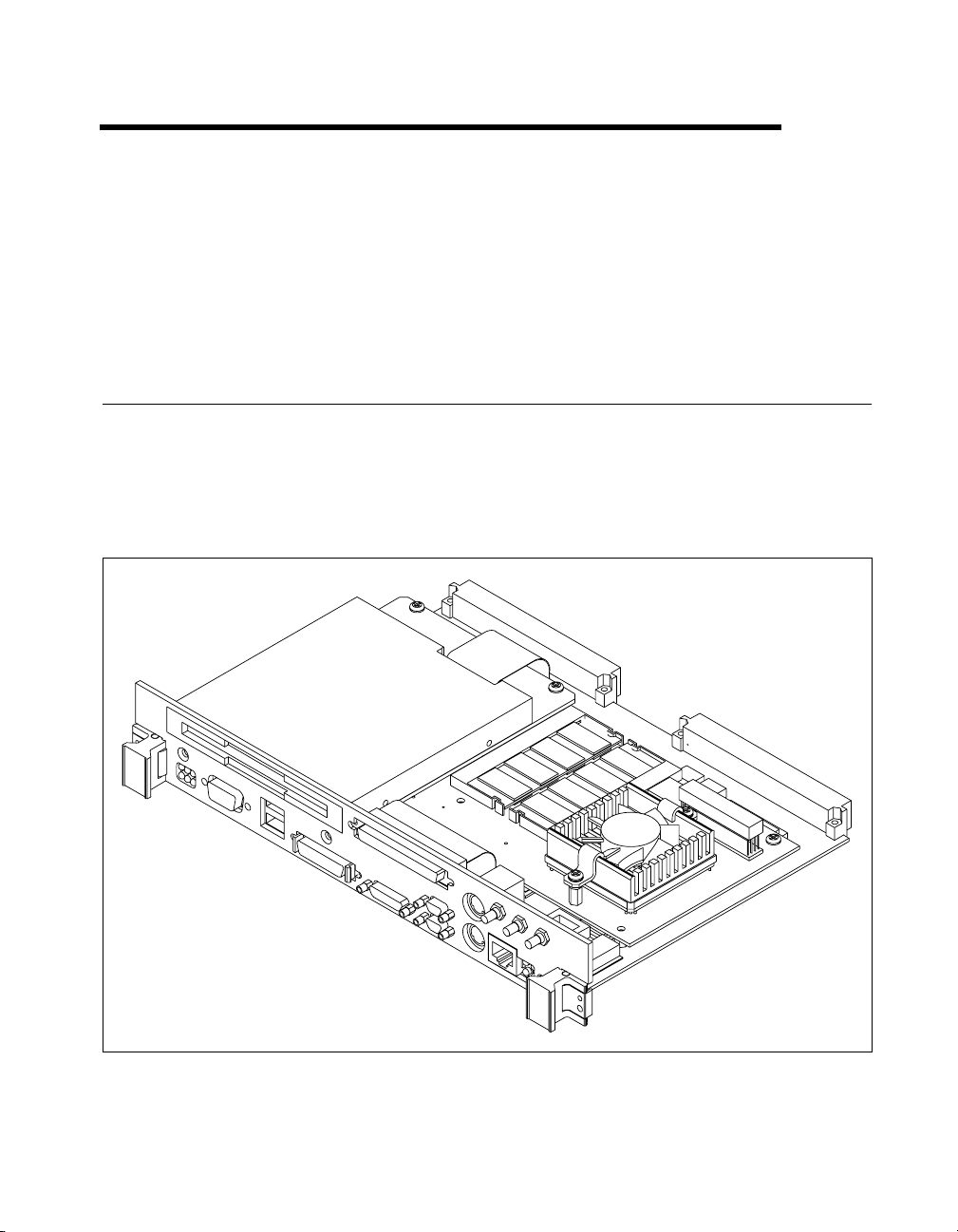
models, which are functionally equivalent in many ways. Figure 1-1
shows the VXI mode l and Figure 1- 2 shows the VME model. Refer to
Appendix C, Front Panel and Connectors, for information about the
location and pinout assignment of each connector on the module.
1
Figure 1-1.
©
National Instruments Corporation 1-1 VXI/VMEpc 600 Series User Manual
VXIpc-650 Embedded Controller
Page 13
Chapter 1 Introduction
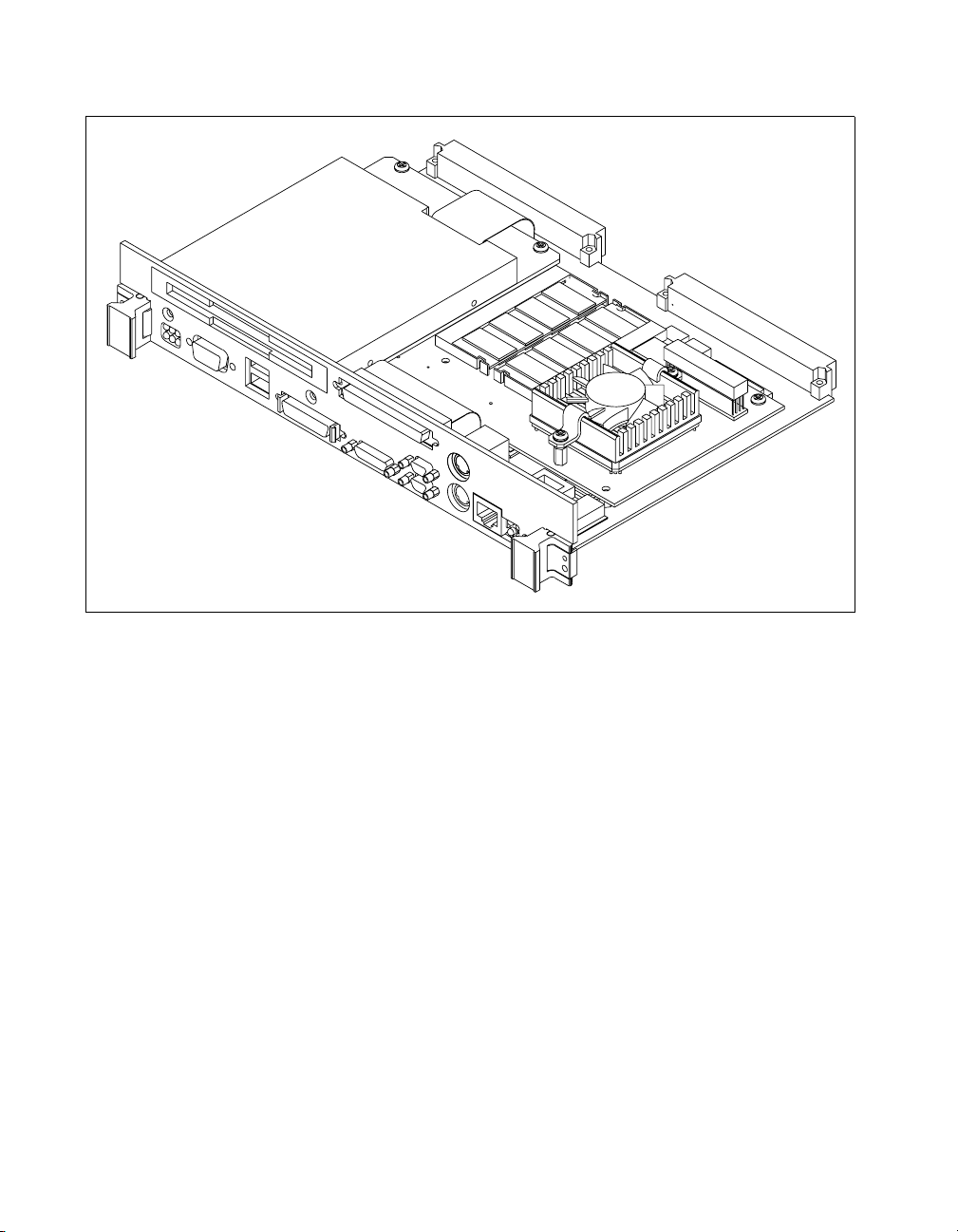
Figure 1-2.
The VXI/VMEpc 600 Series controllers are B-size, embedded computers
based on x86 Processor architecture and on the Peripheral Component
Interface (PCI) bus. These computers are high-performance, easy-to-use
platforms for controlling VXI/VMEbus systems, featuring complete V XI
and VME functionality through interactive utilities and C function calls. In
addition, the VXI/VMEpc 600 Series has Ethernet capabilit y plus an
IEEE 488.2 interface that is compatible with the NI-488.2 architecture.
The VXI/VMEpc 600 Series is a custom computer that you install directly
in two B-size slots of your VXI or VME mainframe. An embedded
computer can take full advantage of the VXI/VME high-performance
backplane capabilities and give you direct control of VXI registers,
memory, interrupts, and triggers.
All models in the VXI/VMEpc 600 Series are fully VXIplug&play
compliant and are compatible with PC-compatible software tools, the
National Instruments LabVIEW and LabWindows/CVI application
software, and the NI-VXI, NI-VISA, and NI-488.2 bus interface software.
VXI/VMEpc 600 Series User Manual 1-2
VMEpc-650 Embedded Controller
©
National Instruments Corporation
Page 14

Optional Equipment
You can contact National Instruments to order any of the following
optional equipment:
• COM1/2 adapter cable
• Enhanced parallel port adapter cable
• Single-shielded 2 m GPIB cable
National Instruments Software
National Instruments has developed s everal sof tware kits yo u can use with
the VXI/VMEpc 600 Series. The NI-VXI bus interface software includes
a Resource Manager, an interactive VXI resource editor program,
a comprehensive lib rary of software routin es for VXI/VME programming,
and an interactive control program for interacting with VXI/VME. You
can use this software to seamlessly program multiple-mainframe
configurations and have software compatibility across a variety of
VXI/VME controller platforms.
The NI-488.2M software kit gives you access to the industry-standard
NI-488.2M software for controlling e xternal GPIB instruments thro ugh the
GPIB port on the front panel of your VXI/VMEpc 600 Series. The GPIB
interface on your VXI/VMEpc controller is fully compatible with the
NI-488.2M driver for a variety of operating systems. Any software using
NI-488.2M will run on the VXI/VMEpc 600 Series.
Chapter 1 Introduction
You can use the NI-VISA high-level programm in g API to program GPIB,
serial, parallel, and VXI/VME devices in much the same manner.
You can also use the National Instruments LabVIEW and
LabWindows/CVI application programs and instrument drivers to
ease your programming task. These standardized programs match the
modular virtual instrument capability of VXI and can redu ce your
VXI/VMEbus software development time. These programs are fully
VXIplug&play compliant and feature extensive libraries of GPIB, Serial,
and VXI instrument drivers written to take full advantage of direct VXI
control. LabVIEW and LabWindows/CVI include all the tools needed for
instrument control, data acquisition, analysis, and presentation.
LabVIEW is a complete programming environment that departs from the
sequential nature of traditional programming languages and features a
graphical programming environment.
©
National Instruments Corporation 1-3 VXI/VMEpc 600 Series User Manual
Page 15

Chapter 1 Introduction
LabWindows/CVI is an interactive C development environment for
building test and measurement and instrument control systems. It includes
interactive code-gener ation tools and a graphical editor for building custom
user interfaces.
Hardware Description
VXI Slot 0 Functionality
You can use the VXIpc 600 Series computers to achieve full VXI Slot 0
control of your VXI system. You can also install the module in another slot
and use it in Non-Slot 0 mode. You do not have to change any jumpers
when moving between these two modes, as the VXIpc 600 Series
automatically detects whether it is installed in Slot 0 and automatically
enables or disables the onboard Slot 0 circuitry.
VME Slot 1 Functionality
In the same way, you can install the VMEpc-650 in Slot 1 for full System
Controller functionality, or you can use it in Non-Slo t 1 mode. The
VMEpc-650 automatically detects whether it is in the System Controller
slot and it automatically enables or disables the onboard Slot 1 circuitry.
Custom Application-Specific Interface Chips
The VXI/VMEpc 600 Series uses the MITE and MANTIS custom ASICs
to deliver high VXI/VME performance DMA block-mode data transfer
rates across the VXI/VME backplane.
The VXI/VMEpc 600 Series h as the TNT4882C custom ASIC t o give full
GPIB control of external instruments via a front-panel connector. GPIB
capability is fully compatible with IEEE 488.2 and the industry -standard
NI-488.2 driver for a variety of operating systems.
The MITE custom ASIC is a sophisticated dual-channel DMA controller
with standard interfaces for VXI and PCI. By using MITE DMA to transfer
data and commands to and from devices, the MITE frees the computer’s
microprocessor to perform other tasks such as data analysis and
presentation. In addition to DMA, the MITE incorporates the new VME64
MBLT—8-byte block transfers in which both the addr ess b us and d ata b u s
are used to transfer data—directly into the ASIC to perform the fastest
transfer operation to instruments. With the multiple windowing scheme of
the MITE, you can easily access all of VXI/VME address space.
VXI/VMEpc 600 Series User Manual 1-4
©
National Instruments Corporation
Page 16

Chapter 1 Introduction
♦ VXI users only—The VXI trigger interface on the VXIpc 600 Series
controller is based on the MANTIS cu stom AS IC. The f ron t panel has t wo
SMB trigger I/O connectors, which you can use to route any of the TTL
trigger lines between the backplane and external devices. The MANTIS
ASIC on the controller provides the complete VXI interface to the
backplane connector in a single chip. The VXIpc 600 Series can respond
to all VXI-defined protocols on all P2 TTL and ECL trigger lines at the
same time. The MANTIS features an internal cross-matrix switching
system for routing between lines as well as to and from the front panel and
onboard clocks.
Note The MANTIS ASIC contains the exac t functionality of the TIC ASIC, which
appeared on the VXIpc-486 Model 500 Series controllers. Any application that
currently uses any of the TIC functionality, such as the crosspoint switch and
counter/timers, can run on a contr oller containing the MANTIS ASIC without
modification.
Front Panel Features
The VXI/VMEpc 600 Series has the following front-panel features:
• Internal 3.5 in. floppy drive
• System reset push-button
• Up to 14 front-panel connectors as listed below:
– Two RS-232 Serial
– Extended Capabilities Parallel (ECP)
–Super VGA
– GPIB (IEEE 488.2)
– 10/100 BaseT Ethernet
– Ultra Wide SCSI
– PS/2-Style Keyboard
– PS/2-Style Mouse
– Two Universal Serial Bus (USB)
– External Clock (VXIpc only)
– Trigger Output (VXIpc only)
– Trigger Input (VXIpc only)
• Six front-panel LEDs that show VXI and PC status:
– SYSF LED indicates that the VXI/VMEbus SYSFAIL line is
asserted.
©
National Instruments Corporation 1-5 VXI/VMEpc 600 Series User Manual
Page 17
Chapter 1 Introduction
– FAIL LED indicates that the VXI/VMEpc-650 is driving the
SYSFAIL signal.
– TEST LED indicates that the VXI/VMEpc-650 is performing its
self-tests or startup Resource Manager operations.
– ONLINE LED indicates that the VXI/V MEpc-650 is perf orming
or has completed its startup Resource Manager operations.
– ACC LED indicates when the VXI/VMEpc-650 MODID line is
asserted or the VXIbus registers or shared memory are accessed
by another bus master.
– DRV LED indicates when the internal hard drive is in use.
• Four front-panel LEDs that show Ethernet port status:
– RX LED indicates that the VXI/VMEpc-650 Series is receiving
data through its Ethernet port.
– TX LED indicates that the VXI/VMEpc-650 Series is transmitting
data through its Ethernet port.
– LNK LED reflects Ethernet link status.
– 100B-T LED indicates Fast Ethernet Link at 100 Mbits/s when lit.
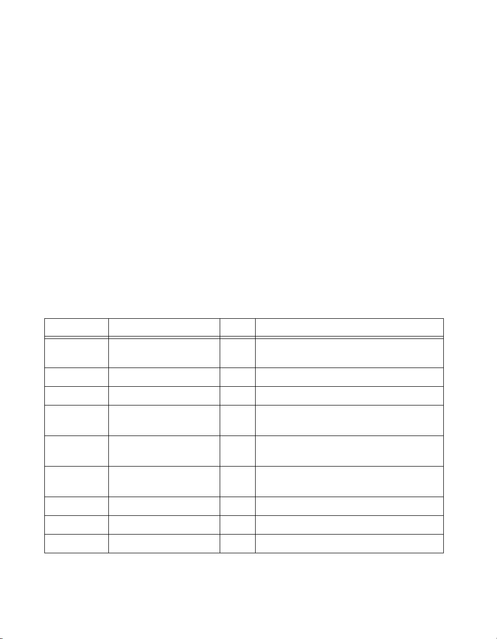
Table 1-1.
VXI/VMEpc 600 Series Peripherals Overview
Peripheral External Connector Bus Function
Video 15-pin DSUB
(standard VGA)
PCI High-resolution/color support for a
Super VGA monitor
IDE None PCI Support for internal fast ATA-2 hard drive
Ethernet RJ-45 PCI 10/100 BaseT Ethernet connection
SCSI 68-pin UW-SCSI PCI External connection for hard drives,
CD-ROM drives, and so on
GPIB 24-pin CHAMP ISA IEEE 488.2 interface compatible with the
National Instruments AT-GPIB/TNT
VXI Two 96-pin DIN
PCI High-performance VXIbus interface
(rear of board)
Serial Serial Port (Mini DSUB) ISA 16550 serial ports
Parallel Parallel Port (IEEE 1284) ISA Extended capabilities
USB Four-wire USB PCI Universal Serial Bus device
VXI/VMEpc 600 Series User Manual 1-6
©
National Instruments Corporation
Page 18

Functional Overview
This chapter contains functional descriptions of each major logic block on
the VXI/VMEpc 600 Series.
VXI/VMEpc 600 Series Functional Description
The VXI/VMEpc 600 Series is a VXI/VMEbus embedded controller in a
B-size form factor. It includes many high-performance peripherals that
normally require add-in cards on desktop PCs. In addition, it has a
VXI/VMEbus interface that is controlled from the PCI local bus, providing
extremely high performance and reliability.
2
©
National Instruments Corporation 2-1 VXI/VMEpc 600 Series User Manual
Page 19
Chapter 2 Functional Overview
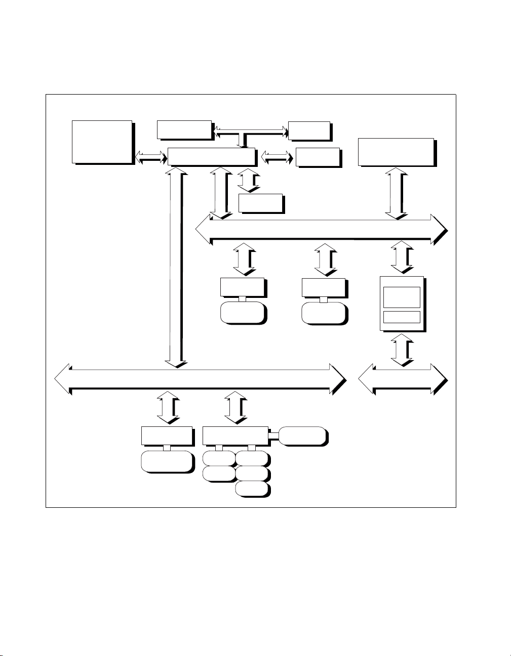
Figure 2-1 is a functional block diagram of the VXI/VMEpc 600 Series.
Following the diagram is a description of each logic block shown.
PCI-Based Pentium
Memory
Cache
Chipset
SCSI
SCSI
SCSI-2
SCSI
Connector
CPU
USB (2)
EIDE
32-Bit, 5 Volt PCI Local Bus
10/100
SCSI
Ethernet
SCSI-2
RJ-45
Video
VXI/VME
MITE
MANTIS
VXI/VME BusISA Bus
GPIB PC Peripherals
Miniature
GPIB
Connector
ECP
Parallel
Miniature
Serial (2)
Keyboard
Mouse
Reset
Figure 2-1.
VXI/VMEpc 600 Series User Manual 2-2
Floppy
VXI/VMEpc 600 Series Block Diagram
©
National Instruments Corporation
Page 20

Chapter 2 Functional Overview
The VXI/VMEpc 600 Series consists of the following logic blocks:
Video The video circuitry is a plug-in PCI card that has
a 64-bit data path and 2 MB of EDO DRAM.
IDE This is dedica t ed IDE circuitry providing fast
ATA-2 transfers to the internal hard drive.
VXI/VME This is the PCI-VXI/VMEbus interface
circuitry. The MITE is a National Instruments
ASIC developed to efficiently manage data
transfers between the VXI/VMEbus and the
processor (via the PCI bus). The MANTIS ASIC
(also developed by National Instruments)
performs VXI/VMEbus arb itration and manages
VXIbus interrupts and triggers. Also part of the
VXIbus interface are the SMB connectors,
which you can use to route triggers and the
CLK10 signal to or from the VXIbus.
Ethernet This is an PCI-based Ethernet circuit. It uses an
RJ-45 connector for access to an external
Ethernet 10/100 Base-T LAN.
GPIB This is the IEEE 488.2 port. It uses the National
Instruments TNT4882 ASIC for maximum
performance as an ISA-based GPIB controller.
PC Peripherals These block s represent the other peripherals
supplied by the VXI/VMEpc 600 Series. The
VXI/VMEpc 600 Series has PS/2 mouse and
keyboard ports, two miniature serial ports, an
ECP/EPP parallel port, reset button, and a
1.44 MB, 3.5 in. floppy drive.
System I/O This block has the bridge between the PCI bus
and the ISA bus. It also has PCI bus arbitration
logic and integrates PC-specific hardware such
as the DMA and interrupt controllers.
SCSI The SCSI circuitry uses a PCI-SCSI bridge to
provide a flexible Ultra Wide SC SI connection
on the front panel, usable for such devices as
external hard disks and CD-ROM drives.
©
National Instruments Corporation 2-3 VXI/VMEpc 600 Series User Manual
Page 21

Configuration and Installation
This chapter contains the instructions to configure and install the
VXI/VMEpc 600 Series. Unless otherwise noted, these instructions apply
to all models in the VXI/VMEpc 600 Series, which currently consists of the
VXIpc-650 and the VMEpc-6 50.
3
Caution
!
Electrostatic discharge can damage several components on your VXI/VMEpc 600
Series module. T o avoid such damage in handling the module, touch the antistatic
plastic package to a metal part of your VXI chassis before removing the modu le
from the package.
Default Settings
This section summarizes the hardware default settings for the
VXI/VMEpc 600 Series for easy reference. The module is set at the
factory for the most commonly used configuration.
©
National Instruments Corporation 3-1 VXI/VMEpc 600 Series User Manual
Page 22
Chapter 3 Configuration and Installation
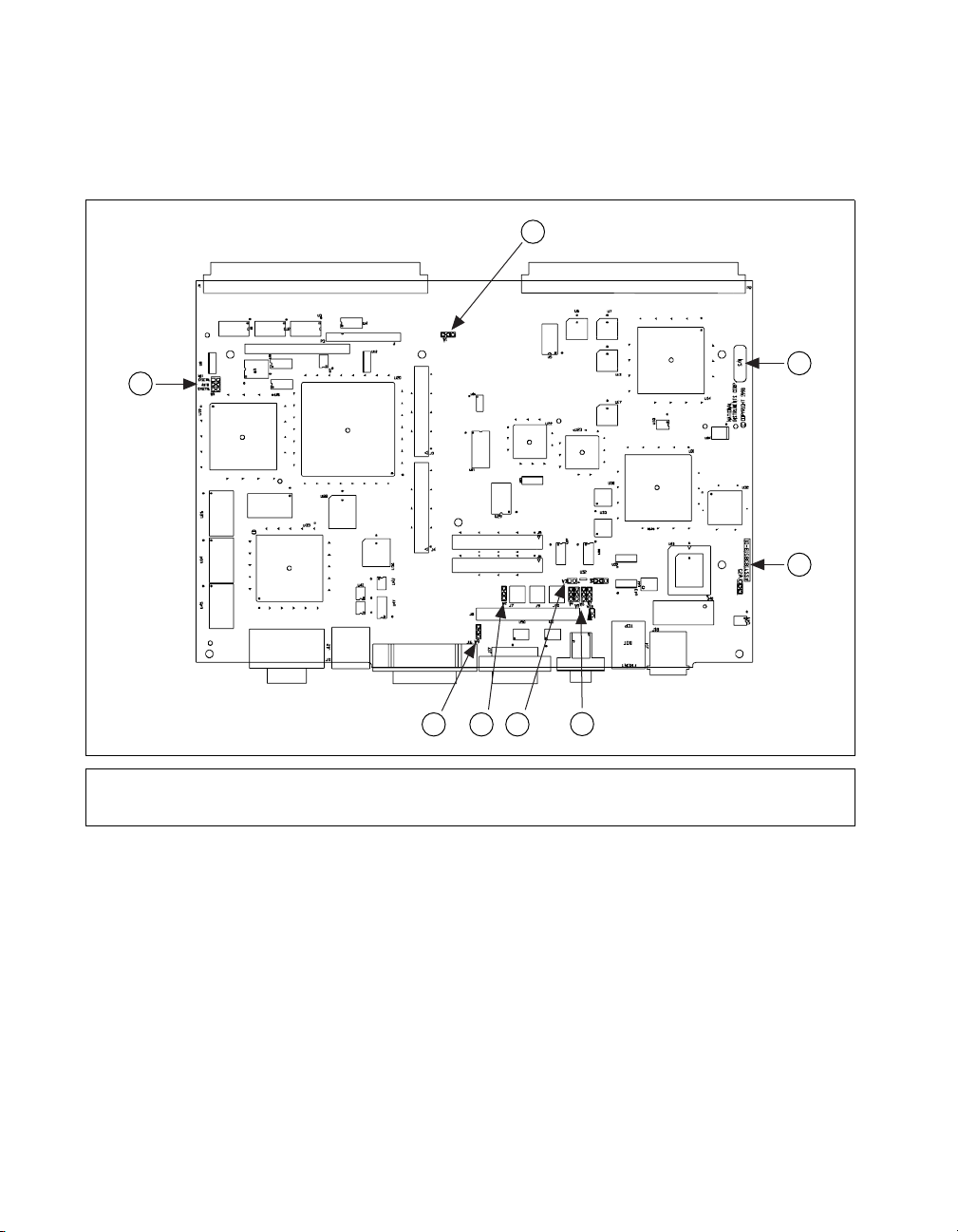
Figure 3-1 shows the location of the user-configurable jumpers on the
VXIpc-650 base board. The figure also shows the location of the serial and
assembly numbers.
1
2
3
4
1W11
2W1
3 Serial Number
4 Assembly Number
5 W4–W7
6W3
Figure 3-1.
VXI/VMEpc 600 Series User Manual 3-2
678
5
7W2
8W9
VXIpc-650 Parts Locator Diagram
©
National Instruments Corporation
Page 23
1
Chapter 3 Configuration and Installation
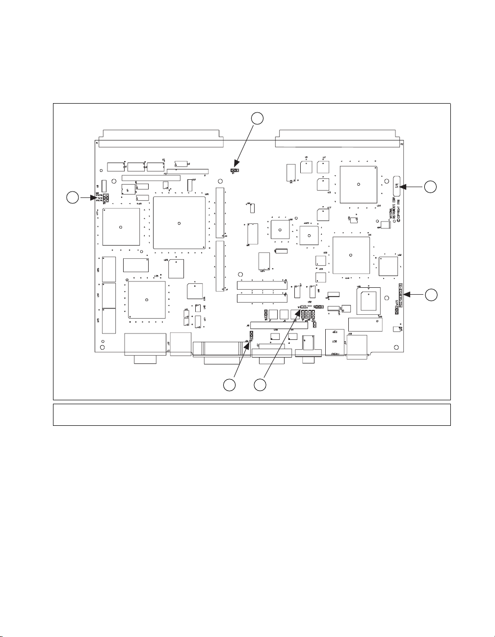
Figure 3-2 shows the location of the user-configurable jumpers on the
VMEpc-650 base board. The figure also shows the location of the serial
and assembly numbers.
2
3
4
6
1W11
2W1
3 Serial Number
4W8
Figure 3-2.
©
National Instruments Corporation 3-3 VXI/VMEpc 600 Series User Manual
5
5W3
6W9
VMEpc-650 Parts Locator Diagram
Page 24
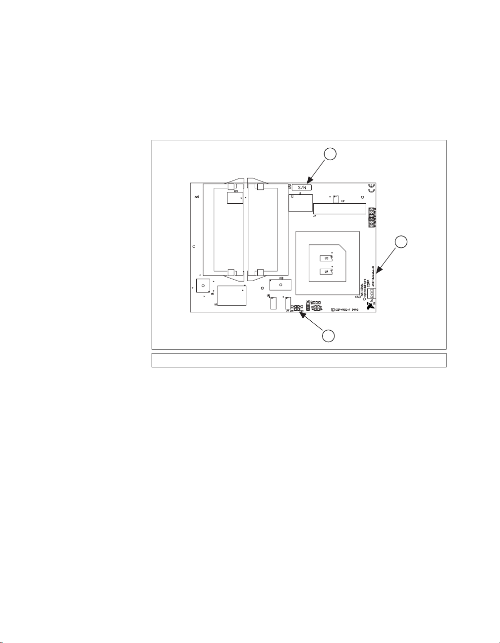
Chapter 3 Configuration and Installation
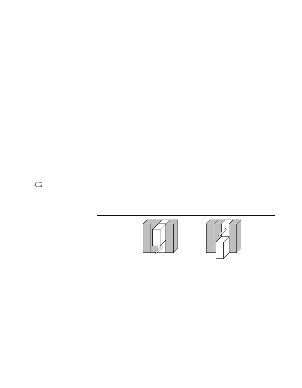
One of the user-confi gurable jumpers, W20, is located on the CPU mo dule
attached to the base board. Figure 3-3 shows the location of the W20
jumper, which controls the system CMOS setting. Notice that you do not
have to remove the CPU module from the base board to configure any of
the jumpers on either board. Refer to the System CMOS section later in this
chapter for more information.
1
2
1 Serial Number 2 Assembly Number 3W20
Figure 3-3.
VXI/VMEpc 600 Series User Manual 3-4
3
CPU Module Attached to VXI/VMEpc-650
©
National Instruments Corporation
Page 25
Chapter 3 Configuration and Installation
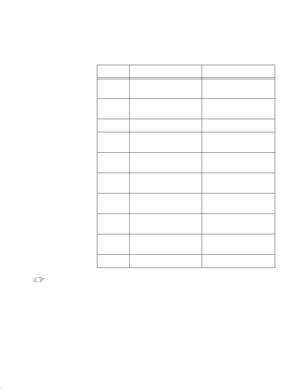
Table 3-1 lists the factory-default settings and options for the onbo a rd
jumpers and switches.
Table 3-1.
VXI/VMEpc 600 Series Hardware Default Settings
Jumper Default Setting Optional Setting
W1 Enable MITE
self-configuration
W2 No termination on
external trigger inpu t
Disable MITE
self-configuration
T erminate e xternal trigger
input to 50 Ω
W3 Supply SCSI termination Disable SCSI termination
W4 Receive CLK10 input
from SMB
W5 No termination on CLK10
input
W6 Source CLK10 from
Source CLK10 output to
SMB
Terminate CLK10 input
to 50 Ω
Source CLK10 from SMB
onboard oscillator
W7 Non-inverted CLK10
Inverted CLK10 output
output
W9 MITE user configuration MITE factory
configuration
W11 Enable automatic slot
detection
Force System Controller;
Force Non-System Cont.
W20 Normal CMOS operation Clear CMOS
Note Please do not adjust the jumpers on any jumper blocks not listed in Table 3-1
unless directed by National Instr uments support.
©
National Instruments Corporation 3-5 VXI/VMEpc 600 Series User Manual
Page 26

Chapter 3 Configuration and Installation
Configuring the VXI/VMEpc 600 Series
This section describes how to configure the following options on the
VXI/VMEpc 600 Series:
• VXI/VMEbus System Controller/Non-System Controller
• VXIbus CLK10 routing (VXIpc only)
• Trigger input termination (VXIpc only)
• MITE EEPROM
VXI/VMEbus System Controller/Non-System Controller
The VXI/VMEpc 600 Series is configured at the factory to automatically
detect if it is installed in Slot 0 of a VXIbus mainframe (or Slot 1 in a
VMEbus chassis). With automatic System Controller slot detection, you
can install the module into any VXI/VMEbus slot.
You can manually configure the VXI/VMEpc 600 Series for either
System Controller or Non-System Controller operation by defeating the
automatic-detection circuitry. Use the three-position jumper W11 to select
automatic detection, System Controller, or Non-System Controller
operation. Figure 3-4 shows these three settings.
Caution
!
Do not install a device configured for System Controller into another slot without
first reconfiguring it to either Non-System Controller or automatic-detection
configuration. Neglecting to do this could resu lt in damage to the device, the
VXI/VMEbus backplane, or both.
Not
SYSCTRL
Auto
SYSCTRL
W11
a. Manual Configuration
for Non-System Controller
Figure 3-4.
VXI/VMEpc 600 Series User Manual 3-6
Not
SYSCTRL
Auto
SYSCTRL
W11
b. Automatic System
Controller Slot
Detection (Default)
System Controller Slot Configuration
Not
SYSCTRL
Auto
SYSCTRL
c. Manual Configuration
for System Controller
©
National Instruments Corporation
W11
Page 27
When the VXI/VMEpc 600 Series is installed in Slot 0 of a VXI system or
Slot 1 of a VME system, it becomes the VXI/VMEbus System Controller.
In this role, it has VXI/VMEbus Data Transfer Bus Arbiter circuitry that
accepts bus requests on all four VXI/VMEbus request levels, prioritizes
the requests, and grants the bus to the highest priority requester. As
VXI/VMEbus System Controller, the VXI/VMEpc 600 Series also drives
the 16 MHz VXI/VMEbus system clock by an onboard 16 MHz oscillator.
♦ VXIpc 600 Series Only—As required by the VXIbus specification, the
VXIpc 600 Series drives the 10 MHz signal CLK10 on a differential ECL
output when instal led in Slot 0. When not installed i n Slot 0, the VXIpc 600
Series only receives the CLK10 signal.
VXIbus CLK10 Routing (VXIpc 600 Series Only)
When the VXIpc 600 Series is installed in Slot 0 of your mainframe, it
supplies the VXIbus CLK10 signal. The VXIpc 600 Series can use two
different sources to generate this signal: an onbo ard oscillator, or the
external CLK SMB connector. Use jumper W6 to select these options,
as shown in Figure 3-5.
Chapter 3 Configuration and Installation
Note
Figures3-5 through 3-8 each highlight one jumper in a block of four jumpers.
The other three jumpers are grayed out to focus your attention to the specific
jumper.
W4 W5 W6 W7
a. CLK10 Generated from
Onboard Oscillator
(Default)
Figure 3-5.
VXIbus CLK10 Routing
b. CLK10 Generated
from SMB
©
National Instruments Corporation 3-7 VXI/VMEpc 600 Series User Manual
Page 28

Chapter 3 Configuration and Installation
The VXIpc 600 Series can also be config ured to dri v e the e xternal CLK10
SMB from the VXIbus CLK10 signal. Jumper W4 controls whether the
VXIpc 600 Series drives or receives the external CLK10 SMB. If you
change the W4 setting to drive CLK10 out the external CLK10 SMB
connector (Figure 3-6b), do not set W6 to source CLK10 to the backplane
from the SMB; instead use the setting shown in Figure 3-5a.
W4 W5 W6 W7
a. CLK10 SMB Receives
10 MHz Signal (Default)
b. CLK10 SMB Drives 10 MHz
Signal from VXIbus CLK10
Figure 3-6.
SMB CLK10 Direction
When jumper W4 is set so that the VXIpc-650 receives the SMB CLK10
signal, you have the option to add a 50 Ω termination to the signal by
setting W5. W5 is unused—its setting does not matter—when W4 is
configured to drive the external CLK SMB signal. Figure 3-7 shows the
settings for switch W5.
W4 W5 W6 W7
a. Does Not Terminate CLK10
SMB Input (Default)
Figure 3-7.
SMB CLK10 Termination
b. Terminates
CLK10 SMB Input
VXI/VMEpc 600 Series User Manual 3-8
©
National Instruments Corporation
Page 29

Chapter 3 Configuration and Installation
Y ou can use an additional switch, W7, to control the polarity of the external
CLK SMB signal when W4 is configured to drive it. W7 is unused—its
setting does not matter—when W4 is configured to receive the external
CLK SMB signal.
W4 W5 W6 W7
a. Noninverted CLK10
Output from SMB
(Default)
b. Inverted CLK10
Output from SMB
Figure 3-8.
SMB CLK10 Polarity
Trigger Input Termination (VXIpc 600 Series Only)
You can use jumper W2 to terminate the external trigger input SMB
with 50 Ω to ground. Figure 3 -9a shows the default setting for a
non-terminated trigger input SMB. Use the setting of Figure 3-9b to
terminate the trigger input SMB.
W2
a. Does Not Terminate
Trigger Input (Default)
Figure 3-9.
SMB Trigger Input Termination
W2
b. Terminate
Trigger Input
©
National Instruments Corporation 3-9 VXI/VMEpc 600 Series User Manual
Page 30

Chapter 3 Configuration and Installation
MITE EEPROM
The VXI/VMEpc 600 Series has an onboard EEPROM, which stores
default register values for the VXI/VME circuitry. These values are loaded
when you power up the computer. These values read from the EEPROM
tell the PCI interface of the VXI/VMEbus registers so that the VXI/VME
interface is ready to respond to Resource Manager accesses within the
required 5 s of SYSRST* deasserting. You can use jumper W1 to disable
this power-on self-configuration (POSC) circuit. Although this make s the
VXI/VME circuitry unusable, it is sometimes helpful in debugging address
and interrupt conflicts with add-in boards. In general, however, you should
leave jumper W1 in its factory-default setting. Figure 3-10 shows the
possible configurations for W1.
W1 W1
a. VXI Circuitry Loads Power-on
Defaults from EEPROM
(Default)
b. Power-on Self Configuration
Circuit is Disabled
Figure 3-10.
The EEPROM is divided into two halves; one half is factory configured
and one half is user configurable. Use jumper W9 to control the operation
of the EEPROM. The setting of this jumper determines whether the
VXI/VMEpc 600 Series boots off the factory-configured half or the
user-modified settings. This is useful in the event that the user-configured
half of the EEPROM becomes corrupted in such a way that the
VXI/VMEpc 600 Series boots to an unusable state. In its default setting,
the V XI/VMEpc 600 Series boots off the user-configurable half.
VXI/VMEpc 600 Series User Manual 3-10
Power-on Self Configuration Status
©
National Instruments Corporation
Page 31

Chapter 3 Configuration and Installation
Figure 3-11 shows the configuration settings for EEPROM operation.
W9
a. Boot from User
Configuration (Default)
Figure 3-11.
b. Boot from Protected
EEPROM Configuration
W9
Configuration
How to Fix an Invalid EEPROM Configuration
The NI-VXI software includes a configuration utility you can use to edit
the configuration of the VXI/VMEpc 600 Series. Use T&M Explor er under
Windows 95/NT. Some of these settings are stored in files that are read
by the NI-VXI software, while other settings are stored directly in the
VXI/VMEpc 600 Series EEPROM. Certain EEPROM configurations can
lock up your computer while it is booting up. Generally, only the size and
location of the memory windows can cause your VXI/VMEpc 600 Series
to lock up your system. For example, many PCI-based computers will not
boot if a board in its system requests more memory space th an the computer
can allocate. If you encounter this situation you should reduce the size of
the VXI/VMEpc 600 Series user window.
If this situation occurs after you change the configuration, perform the
following steps to reconfigure the VXI/VMEpc 600 Series:
1. Turn off your computer.
Warning To protect both yourself and the mainframe from electrical hazards, the
mainframe should remain off until you are finished changing the settings on
the VXI/VMEpc 600 Series.
2. Change jumper W9 to the pos ition shown in Fig ure 3-11b to rest ore the
factory configuration.
3. Turn on the co mputer . The com puter should boot this time because the
factory-default configuration is being used to initialize the
VXI/VMEpc 600 Series.
4. Run your software configuration utility to re-adjust the
VXI/VMEpc 600 Series configuration.
©
National Instruments Corporation 3-11 VXI/VMEpc 600 Series User Manual
Page 32

Chapter 3 Configuration and Installation
5. After saving the configuration, exit Windows and turn off the
computer.
6. Change jumper W9 to the default position, as shown in Figure 3-11a.
7. Turn on the computer. If the computer does not boot with this
configuration, you will have to repeat these steps, modifying your
configuration until a final configuration is reached.
Configuring the PC
This section describes how to configure the following options on the PC:
• SCSI termination
•System CMOS
• Ethernet power-on defaults
SCSI Termination
The VXI/VMEpc 600 Series uses active termination on the UW-SCSI bus.
Because the VXI/VMEpc 600 Series is always an end device, you should
not need to disable the termination; however, for informational purposes
Figure 3-12 shows the jumper settings for both enabled and disabled
termination.
W3
a. Terminate SCSI
Signals (Default)
Figure 3-12.
System CMOS
The VXI/VMEpc-650 contains a backed-up memory used to store BIOS
defaults and configuration information:
Follow this procedure to clear the CMOS contents:
1. Place the jumper as shown in Figure 3-13b to short the pins of W20,
which is located on the CPU module.
Caution
!
VXI/VMEpc 600 Series User Manual 3-12
Do not keep these two pins shorted because the CMOS memory cannot be
sustained when the power is turned off in this state.
W3
b. Do Not Terminate
SCSI Signals
SCSI Termination
©
National Instruments Corporation
Page 33

Chapter 3 Configuration and Installation
2. Power-on the VXI/VMEpc- 650. The screen shou ld briefly appear , and
then go black.
3. Power-off the VXI/VMEpc-650.
4. Remove the jumper as shown in Figure 3-13a to restore normal
operation.
W19 W20
a. Normal Operation
(Default)
Figure 3-13.
W19 W20
b. Clear CMOS
Contents
System CMOS
Installing the VXI/VMEpc 600 Series
This section contains general installation instructions for the
VXI/VMEpc 600 Series. Consult your VXI/VMEbus mainframe user
manual or technical reference manual for specific instructions and
warnings.
1. Plug in your mainframe before inst alling the VXI/VMEpc 600 Series.
The power cord grounds the mainframe and protects it from electrical
damage while you are installing the module.
Warning To protect both yourself and the mainframe from electrical hazards,
the mainframe should remain off until you are finished installing the
VXI/VMEpc 600 Series module.
2. Remove or open an y doors or covers bl ocking access to the mainframe
slots.
Caution If the VXI/VMEpc 600 Series is not configured for automatic System Controller
!
detection, be certain that the slot you select in your VXI/VMEbus mainframe
matches the VXI/VMEpc 600 Series configuration as eith er a System Controller
device or a Non-System Controller device. Installing the VXI/VMEpc 600 Series
into a slot that does not correspond with the jumper setting can damage the
VXI/VMEpc 600 Series, the VXI/VMEbus backplane, or both.
3. Insert the VXI/VMEpc 600 Series in the slot you have selected by
aligning the top and bottom of the module with the card-edge guides
inside the mainframe. Slowly push the VXI/VMEpc 600 Series
straight into the slot until its plug connectors are resting on the
©
National Instruments Corporation 3-13 VXI/VMEpc 600 Series User Manual
Page 34

Chapter 3 Configuration and Installation
backplane receptacle connectors. Using slow, evenly distributed
pressure, press the module straight in until it seats in the expansion
slot. The front panel of the VXI/VMEpc 600 Series should be even
with the front panel of the mainframe.
4. Tighten the retaining screws on the top and bottom edges of the front
panel.
5. Check the installation.
6. Connect the keyboard and mouse to the appropriate connectors. Use
the keyboard adapter cable that your received with your kit to adapt
AT-style keyboards to the VXI/VMEpc 600 Series mini-DIN
connector.
7. Connect the VGA monitor video cable to the VGA connector.
8. Connect devices to ports as required by your system configuration.
Some ports, such as the COM ports, have adapter cables that you can
order from National Instruments.
9. Replace or close any doors or covers to the mainframe.
VXI/VMEpc 600 Series User Manual 3-14
©
National Instruments Corporation
Page 35

BIOS
This chapter contains information on the BIOS (Basic Input Output
System), the low-level interface between the hardware and PC software
that configures and tests your hardware at boot up. The BIOS has an
easy-to-use graphical user interface you use to configure system aspects
according to your needs.
Entering BIOS Setup
To enter the BIOS setup program, perform the following steps:
1. Turn on or reboot the system. A screen appears with a series of
diagnostic checks.
2. When
press the <DEL> key to enter the BIOS setup program.
3. Choose options with the keybo a rd. Modify the settings to reflect
system options.
4
Hit <DEL> if you want to run SETUP appears,
Default BIOS Setup Settings
To restore the default settings while inside the BIOS setup program,
select either Auto Configuration with Optimal Settings or Auto
Configuration with Fail-Safe Settings.
Select the Optimal settings if you want to get maximum performance from
the VXI/VMEpc 600 Series. Fail Safe settings are more conservative
settings.
©
National Instruments Corporation 4-1 VXI/VMEpc 600 Series User Manual
Page 36

Specifications
This appendix describes the environmental, electrical, and mechanical
specifications of the VXI/VMEpc 600 Series. Unless otherwise specified,
these specifications apply to all models in the VXI/VMEpc 600 Series.
Requirements
VXIbus Conf i guration Space 64 KB
A24 or A32 Space 16 KB minimum (programmable)
Electrical
A
Characteristic Specification
Current (A)
Voltage (V)
+5 6.5 A 12 A
–5.2 224.5 mA 2 A
–2 67.2 mA 2 A
+12 112.6 mA 2 A
–12 2.43 mA 2 A
©
National Instruments Corporation A-1 VXI/VMEpc 600 Series User Manual
Typical Maximum (Fused)
Page 37

Appendix A Specifications
Physical
Environmental
Characteristic Specification
Size Two-slot VXI/VMEbus B-size module
Board Dimensions 233.35 by 160 by 1.6 mm
Weight 2.5 lb typical
(16 MB DRAM installed)
Slot Requirements Two VXI/VME B-size slots
Compatibility Fully compatible with VXI Specification
VXI Keying Class Class 1 TTL
MTBF 112,000 hours
Characteristic Specification
Temperature 0° to 50° C functional;
–20° to 70° C storage
Meets IEC 60068-2-1, 2
Relative
Humidity
10% to 90% noncondensing, functional
Meets IEC 60068-2-3
EMI FCC Class A verified, EC verified
Random
Vibration
Functional: 5 to 150 Hz @ .01 A.S.D., 1.204 g
Survival: 10 to 500 Hz @ .02 A.S.D., 3.130 g
Meets IEC 60068-2-34
Sine Vibration 10 to 60 Hz @ .15 mm displacement,
60 to 500 Hz @ 2 g, survival
Meets IEC 60068-2-6
Functional
Shock
VXI/VMEpc 600 Series User Manual A-2
Half-sine shock pulse (11 ms durat ion, 30 g peak )
Meets IEC 60068-2-27
RMS
©
National Instruments Corporation
RMS
Page 38

VMEbus Capability Codes
Capability Code Description
A32, A24, A16 (master) VMEbus master A32, A24, and A16
A32, A24, A16 (slave) VMEbus slave A32, A24, and A16
Appendix A Specifications
addressing
addressing
D64, D32, D16,
D08(EO) (master)
D64, D32, D16,
D08(EO) (slave)
BLT, MBLT (master) VMEbus master block and D64 transfers
BLT, MBLT (slave) VMEbus slave block and D64 transfers
RMW (master) VMEbus master read/modify/write
RMW (slave) VMEbus slave read/mod ify/write transfers
RETRY (master) VMEbus master retry support
RETRY (slave) VMEbus slave retry support
FSD First slot detector
SCON VMEbus System Controller
PRI, RRS Prioritized or Round Robin Select arbiter
ROR, FAIR Release on Request and FAIR bus
VMEbus master D64, D32, D16, and
D08 data sizes
VMEbus slave D64, D32, D16, and
D08 data sizes
transfers
(Automatic Detection)
requester
IH(7-1) Interrupt handler for levels 7-1
I(7-1) Interrupt requester for levels 7-1
D32, D16, D08(O)
(Interrupt Handler)
©
National Instruments Corporation A-3 VXI/VMEpc 600 Series User Manual
VMEbus D32, D16, D08(O) interrupt
handler
Page 39

Appendix A Specifications
Capability Code Description
D32, D16, D08(O)
VMEbus D32, D16, D08(O) interrupter
(Interrupter)
ROAK, RORA Release on Acknowledge or Register
Access interrupter
BTO(x) VMEbus bus timer (programmable limit)
LOCK Can lock the VMEbus for indivisible
transfers
VXI/VMEpc 600 Series User Manual A-4
©
National Instruments Corporation
Page 40

LED Indicators
This appendix describes how to read the LEDs on the front panel to
interpret the status of the VXI/VMEpc 600 Series.
VXIbus Interface Status LEDs
The VXIbus interface status LEDs are located at the top of the module
and include four LEDs: FAIL, SYSF, ONLINE, and TEST. They indicate
the various stages of initialization that occur as the VXI/VMEpc 600 Series
boots. The following paragraphs describe each LED.
SYSF LED
The SYSF LED is lit when the VXI/VMEb us SYSFAIL signal is asserted.
It does not necessarily indicate that the VXI/VMEpc600 Series is asserting
SYSFAIL, only that there is a device in the system asserting SYSFAIL.
FAIL LED
The FAIL LED is lit when th e VXI/VMEpc 600 Series is driving the
SYSF AIL signal. Th e VXI/VMEpc600 Series asserts SYSFAIL when the
P ASSED bit in its VXIbus status register is clear. The P ASSED bit is set by
the power-on self configuration circuitry (POSC) when it has completed
initializing the VXI/VMEbus interface.
B
ONLINE LED
The ONLINE LED is lit when the Resource Manager has successfully
completed and the VXI/VMEbus interface is ready for application
programs.
TEST LED
The TEST LED is lit when the power-on self configuration circuitry is
configuring the VXI/VMEbus interface.
©
National Instruments Corporation B-1 VXI/VMEpc 600 Series User Manual
Page 41

Appendix B LED Indicators
LEDs and System Startup Cycle
T able B-1 shows a system startup c ycle and poss ible points o f failure, up to
and including the state in which the ONLINE LED is asserted.
Table B-1.
LEDs and System Startup Status
Possible Problem if
Step LEDs Lit Status
VXI/VMEpc 600 Fails
1 None Machine just turned on. The VXI/VMEpc 600 Series is not
receiving power.
2 FAIL,
SYSF
Now asserting SYSFAIL because
VXI/VMEbus interface has not
been initialized yet.
Power-on self configuration
(POSC) cannot execute because
of problems with system reset or
because the POSCEN switch is
incorrectly configured.
3 FAIL,
TEST
VXI/VMEbus interface is being
initialized by MITE power-on self
POSC has stalled.
configuration (POSC) circuitry.
4 TEST POSC circuitry has initialized
VXI/VMEbus interface, setting
POSC stalled before clearing the
TEST LED.
PASSED and DONE bits.
5 None POSC cycles are complete. VXI
port is ready to respon d to Resource
Manager inquiries.
POSC completed successfully;
however, the Resource Manager
either hung o r wa s not executed.
6 ONLINE Resource Manager has been
executed, indicating that the VXI
software can now communicate
with the VXI/VMEbus circuitry.
VXI/VMEpc 600 Series User Manual B-2
Resource Manager interface
initialized successfully.
©
National Instruments Corporation
Page 42

If either the SYSF or FAIL LED remains lit, perform the following steps:
1. Power off the mainframe.
2. Remove all other modules from the mainframe.
3. Make sure that the VXI/VMEpc 600 Series jumper settings are correct.
4. Make sure that the VXI/VMEpc 600 Series is seated properly in the
mainframe.
5. Power on the mainframe and observe whether the SYSF and FAIL
LEDs become unlit some time before the operating system boots.
Board Access LEDs
The board access LEDs—ACC and DRV —indicate when b oard resources
have been accessed. The following paragraphs describe these LEDs.
ACC LED
When lit, the ACC LED indicates that the VXI/VMEpc 600 Series MODID
line is asserted or that another VXI/VMEbus master is accessing
VXI/VMEbus shared registers or shared memory.
Appendix B LED Indicators
DRV LED
The DRV LED light indicates that an access to the internal hard disk drive
is occurring.
Ethernet LEDs
The Ethernet LEDs (RX, TX, LNK, and 100B-T) indicate the status of the
Ethernet interface on the VXI/VMEpc 600 Series.
RX LED
The RX LED lights when the Ethernet interface is receiving a packet.
TX LED
The TX LED lights when the Ethernet interface is transmitting a packet.
LNK LED
The LNK LED indicates link status, in this case that the controller is
connected to a valid Ethernet port.
©
National Instruments Corporation B-3 VXI/VMEpc 600 Series User Manual
Page 43

Appendix B LED Indicators
100B-T
The 100B-T LED indicates that the current Ethernet connection is at
100 Mbits/s when lit.
VXI/VMEpc 600 Series User Manual B-4
©
National Instruments Corporation
Page 44

Front Panel and Connectors
This appendix describes the front panel and connectors on the
VXI/VMEpc 600 Series. This material contains the information relevant
to VXIplug&play Specification VPP-8, VXI Module/Mainframe to
Receiver Interconnection.
C
Note
The illustrations in this appendix show the mating face of the conn ectors.
An asterisk (*) after a signal name indicates that the signal is active low.
The VXI/VMEpc 600 Series has the following front panel connectors:
• Two RS-232 Serial
• Extended Capabilities Parallel (ECP)
• SVGA Controller
• IEEE 488.2
• RJ-45 Ethernet
• UW-SC SI
• External Clock (VXIpc-650 only)
• Trigger Output (VXIpc-650 only)
• Trigger Input (VXIpc-650 only)
• PS/2-Style Keyboard
• PS/2-Style Mouse
•Two USB
©
National Instruments Corporation C-1 VXI/VMEpc 600 Series User Manual
Page 45

Appendix C Front Panel and Connectors
Front Panel
Figure C-1 shows the front panel layout o f the VXIpc-650 , and Figure C-2
shows the layout of the VMEpc-650 . The drawings sh ow dimensions
relevant to k ey elements on the front panel. Dimensions are shown in inches
and millimeters, with millimeter dimensions in square b rackets. The front
panel thickness for all models in the VXI/VMEpc 600 Series is 2.49 mm
(0.098 in.).
FAIL
SYSF
O
N
L
I
TEST
N
E
DRV
ACC
2
1
Figure C-1.
VXIpc-650 Front Panel Layout and Dimensions
VXI/VMEpc 600 Series User Manual C-2
G
P
I
B
1
2
TRG
IN
L
N
RX
K
TRG
TX
OUT
RESET
CLK
100B-T
©
National Instruments Corporation
Page 46

Appendix C Front Panel and Connectors
FAIL
SYSF
O
N
L
I
TEST
N
E
DRV
ACC
2
1
G
P
I
B
1
2
Figure C-2.
L
N
RX
K
TX
RESET
100B-T
VMEpc-650 Front Panel Layout and Dimensions
©
National Instruments Corporation C-3 VXI/VMEpc 600 Series User Manual
Page 47

Appendix C Front Panel and Connectors
Keyboard and Mouse
Figure C-3 shows the location and pinouts for the keyboard and mouse
connectors on the VXI/VMEpc 600 Series. Table C-1 gives the name and
description for the keyboard and mouse connector signals.
Amp manufactures a mating connector with part numbers 212437-4
(housing), 212435-7 (ferrule), and 66735-4 (pin contact).
FAIL
SYSF
O
N
L
I
TEST
N
E
DRV
ACC
2
1
4
G
P
I
B
1
2
TRG
IN
L
N
RX
K
TRG
TX
OUT
RESET
CLK
100B-T
6
2
1
2
1
3
4
3
Keyboard
5
6
Mouse
5
FAIL
SYSF
O
N
L
I
TEST
N
E
DRV
ACC
2
1
4
G
P
I
B
1
2
L
N
RX
K
TX
RESET
100B-T
6
2
1
2
1
3
4
3
Keyboard
5
6
Mouse
5
a. VXIpc-650 b. VMEpc-650
Figure C-3.
Keyboard and Mouse Connectors Location and Pinout
Table C-1.
Keyboard and Mouse Connector Signals
Pin Signal Name Signal Descript ion
1 DATA Data
2 NC Not Connected
3 GND Ground
4 +5V +5 volts
5 CLK Clock
6 NC Not Connected
VXI/VMEpc 600 Series User Manual C-4
©
National Instruments Corporation
Page 48

VGA
Appendix C Front Panel and Connectors
Figure C-4 shows the location and pinouts for the VGA connector on the
VXI/VMEpc 600 Series. Table C-2 giv es the name and description for t he
VGA connector signals.
Amp manufactures a mating connector with part numbers 748364-1
(housing) and 748333-2 (pin contact).
FAIL
SYSF
O
N
L
I
TEST
N
E
DRV
ACC
FAIL
O
N
L
I
N
E
DRV
VGA
2
1611
1
51015
G
P
I
B
1
2
TRG
IN
L
N
RX
K
TRG
TX
OUT
RESET
CLK
100B-T
1
G
P
I
B
L
N
K
100B-T
SYSF
TEST
ACC
2
RX
TX
RESET
1611
VGA
51015
1
2
a. VXIpc-650 b. VMEpc-650
Figure C-4.
VGA Connector Location and Pinout
Table C-2.
VGA Connector Signals
Pin Signal Name Signal Descript ion
1 R Red
2 G Green
3 B Blue
4 NC Not Connected
5 GND Ground
6 GND Ground
7 GND Ground
8 GND Ground
©
National Instruments Corporation C-5 VXI/VMEpc 600 Series User Manual
Page 49

Appendix C Front Panel and Connectors
Ethernet
Table C-2.
VGA Connector Signals (Continued)
Pin Signal Name Signal Descript ion
9 NC Not Connected
10 GND Ground
11 NC Not Connected
12 SD Serial Data
13 HSync Horizontal Sync
14 VSync Vertical Sync
15 SC Serial Clock
Figure C-5 shows the location and pinouts for the Ethernet connector
on the VXI/VMEpc 600 Se ries. Table C-3 gives the name and description
for the Ethernet connector signals.
Amp manufactures a mating connector, part number 554739-1.
FAIL
SYSF
O
N
L
I
TEST
N
E
DRV
ACC
2
1
G
P
I
B
1
2
TRG
IN
L
N
RX
K
TRG
TX
OUT
RESET
CLK
100B-T
a. VXIpc-650 b. VMEpc-650
Figure C-5.
VXI/VMEpc 600 Series User Manual C-6
FAIL
SYSF
O
N
L
I
TEST
N
E
DRV
ACC
2
1
G
P
I
1
B
1
2
1
Ethernet
L
N
RX
K
TX
8
RESET
100B-T
8
Ethernet Connector Location and Pinout
©
National Instruments Corporation
Ethernet
Page 50

Appendix C Front Panel and Connectors
COM1 and COM2
Figure C-6 shows the location and pinouts for the COM1 and COM2
connectors on the VXI/VMEpc 600 Series. Table C-4 gives the name and
description for the COM1 and COM2 connector signals.
ITT Cannon manufactures a serial port mating connector, part number
MDSM-9SC-Z11, for the COM1 and COM2 connectors.
Table C-3.
Pin Signal Description
1 Differential Transmit +
2 Differential Transmit –
3 Differential Receive +
4 NC
5 NC
6 Differential Receive –
7 NC
8 NC
Ethernet Connector Signals
©
National Instruments Corporation C-7 VXI/VMEpc 600 Series User Manual
Page 51

Appendix C Front Panel and Connectors
FAIL
SYSF
O
N
L
I
TEST
N
E
DRV
ACC
2
1
1596
COM1
G
P
I
B
1
2
TRG
IN
L
N
RX
K
TRG
TX
OUT
RESET
CLK
100B-T
1596
COM2
FAIL
SYSF
O
N
L
I
TEST
N
E
DRV
ACC
2
1
1596
COM1
G
P
I
B
1
2
L
N
RX
K
TX
RESET
100B-T
1596
COM2
a. VXIpc-650 b. VMEpc-650
Figure C-6.
COM1 and COM2 Connectors Location and Pinout
Table C-4.
COM1 and COM2 Connector Signals
Pin Signal Name Signal Descript ion
1 DCD* Data Carrier Detect
2 RXD* Receive Data
3 TXD* Transmit Data
4 DTR* Data Terminal Ready
5 GND Ground
6 DSR* Data Set Ready
7 RTS* Ready to Send
8 CTS* Clear to Send
9 RI* Ring Indicator
VXI/VMEpc 600 Series User Manual C-8
©
National Instruments Corporation
Page 52

Parallel Port
Appendix C Front Panel and Connectors
Figure C-7 shows the location and p inouts for the IEEE-128 4 connector on
the VXI/VMEpc 600 Series. Table C-5 gi v es t he n ame an d des cript i o n fo r
the IEEE-1284 connector signals.
Amp manufactures a parallel port compatible connector, part
number 2-175677-5.
FAIL
SYSF
O
N
L
I
TEST
N
E
DRV
ACC
2
1
36
18
FAIL
SYSF
O
N
L
I
TEST
N
E
DRV
ACC
2
1
36
Parallel Port
G
P
I
B
19
1
2
TRG
IN
L
N
RX
K
TRG
TX
OUT
RESET
CLK
100B-T
1
G
P
I
B
19
1
2
L
N
RX
K
TX
RESET
100B-T
a. VXIpc-650 b. VMEpc-650
Figure C-7.
Parallel Port Connector Location and Pinout
18
Parallel Port
1
©
National Instruments Corporation C-9 VXI/VMEpc 600 Series User Manual
Page 53

Appendix C Front Panel and Connectors
Table C-5.
Parallel Port Connector Signals
Pin Signal Name Signal Descript ion
1 BUSY* Device Busy
2 SLCTIN* Select Input
3 ACK* Acknowledge
4 FAULT* Fault
5 ERROR Error
6 PD0 Data Bi t 0
7 PD1 Data Bit 1
8 PD 2 Data Bit 2
9 PD3 Data Bit 3
10 PD4 Data Bit 4
11 PD5 Data Bit 5
12 PD6 Data Bit 6
13 PD7 Data Bit 7
14 INIT* Initialize Printer
15 STROBE* Strobe
16 SLCT Select
17 AUTOFD Auto Line Feed
18 +5V +5 Volts
19-35 GND Ground
36 NC Not Connected
VXI/VMEpc 600 Series User Manual C-10
©
National Instruments Corporation
Page 54

Universal Serial Bus
Figure C-8 shows the location and pin outs for the tw o Univ ersal Ser ial Bus
(USB) connectors on the VXI/VMEpc 600 Series. Table C-6 gives the
name and description for the USB connector signals.
Amp manufactures a mating connector, part number 787633.
Appendix C Front Panel and Connectors
FAIL
SYSF
O
N
L
I
TEST
N
E
DRV
ACC
2
1
1
4
G
P
I
B
1
2
L
N
RX
K
TX
RESET
100B-T
1
4
USB
FAIL
SYSF
O
N
L
I
TEST
N
E
DRV
ACC
2
1
1
4
G
P
I
B
1
2
L
N
RX
K
TX
RESET
100B-T
1
4
USB
a. VXIpc-650 b. VMEpc-650
Figure C-8.
USB Connectors Location and Pinout
Table C-6.
USB Connector Signals
Pin Signal Name Signal Descript ion
1 VCC Cable Power (+5 V)
2 –Data USB Data–
3 +Data USB Data+
4 GND Ground
©
National Instruments Corporation C-11 VXI/VMEpc 600 Series User Manual
Page 55

Appendix C Front Panel and Connectors
SCSI
Figure C-9 shows the location and pinouts for the SCSI connector on the
VXI/VMEpc 600 Series. Table C-7 giv es the name and description for t he
SCSI connector signals.
Amp manufactures a SCSI compatible connector, part number 749111-6,
with shielded enclosure 750752-1.
FAIL
SYSF
O
N
L
I
TEST
N
E
DRV
ACC
2
1
68
G
P
I
B
1
2
35
TRG
IN
L
N
RX
K
TRG
TX
OUT
RESET
CLK
100B-T
34
Ultra-wide
SCSI
1
FAIL
SYSF
O
N
L
I
TEST
N
E
DRV
ACC
2
1
68
G
P
I
B
1
2
35
L
N
RX
K
TX
RESET
100B-T
34
1
a. VXIpc-650 b. VMEpc-650
Figure C-9.
Table C-7.
SCSI Connector Location and Pinout
16-Bit Wide SCSI-3 “P” (Primary) Connector Pinout
(Single Ended)
High Density
68-Pin
SCSI Signal
Connector
SCSI Signal
GND 1 DB(12)* 35
Ultra-wide
SCSI
High Density
68-Pin
Connector
GND 2 DB(13)* 36
GND 3 DB(14)* 37
GND 4 DB(15)* 38
GND 5 DP1 39
GND 6 DB(0)* 40
VXI/VMEpc 600 Series User Manual C-12
©
National Instruments Corporation
Page 56

Appendix C Front Panel and Connectors
Table C-7.
16-Bit Wide SCSI-3 “P” (Primary) Connector Pinout
(Single Ended) (Continued)
High Density
68-Pin
SCSI Signal
Connector
SCSI Signal
GND 7 DB(1)* 41
GND 8 DB(2)* 42
GND 9 DB(3)* 43
GND 10 DB(4)* 44
GND 11 DB(5)* 45
GND 12 DB(6)* 46
GND 13 DB(7)* 47
GND 14 DP0 48
GND 15 GND 49
GND 16 GND 50
TERMPWR 17 TERMPWR 51
TERMPWR 18 TERMPWR 52
High Density
68-Pin
Connector
RSRVD 19 RSRVD 53
GND 20 GND 54
GND 21 ATN* 55
GND 22 GND 56
GND 23 BSY* 57
GND 24 ACK* 58
GND 25 RST* 59
GND 26 MSG* 60
GND 27 SEL* 61
GND 28 C/D* 62
GND 29 REQ* 63
GND 30 I/O* 64
©
National Instruments Corporation C-13 VXI/VMEpc 600 Series User Manual
Page 57

Appendix C Front Panel and Connectors
SCSI Signal
GND 31 DB(8)* 65
GND 32 DB(9)* 66
GND 33 DB(10)* 67
GND 34 DB(11)* 68
GPIB (IEEE-488.2)
Figure C-10 shows the location and pi nouts f or th e GPIB co nnector on the
VXI/VMEpc 600 Series. Table C-8 giv es the name and description for t he
GPIB connector signals.
ITT Cannon manufactures a GPIB mating connector, part number
MDSM-255C-Z11.
Table C-7.
FAIL
SYSF
O
N
L
I
TEST
N
E
DRV
ACC
16-Bit Wide SCSI-3 “P” (Primary) Connector Pinout
(Single Ended) (Continued)
High Density
68-Pin
Connector
SCSI Signal
FAIL
SYSF
O
N
L
I
TEST
N
E
DRV
ACC
High Density
68-Pin
Connector
2
1
14
G
P
I
B
1
25
2
TRG
IN
L
N
RX
K
TRG
TX
OUT
RESET
CLK
100B-T
a. VXIpc-650 b. VMEpc-650
Figure C-10.
VXI/VMEpc 600 Series User Manual C-14
2
1
1
13
GPIB
G
P
I
B
L
N
K
14
1
25
2
RX
TX
RESET
100B-T
GPIB Connector Location and Pinout
©
National Instruments Corporation
1
GPIB
13
Page 58

Appendix C Front Panel and Connectors
Table C-8.
GPIB Connector Signals
Pin Signal Name Signal Descript ion
1 DIO1* Data Bit 1
2 DIO2* Data Bit 2
3 DIO3* Data Bit 3
4 DIO4* Data Bit 4
5 EOI* End or Identify
6 DA V* Data Valid
7 NRFD* Not Ready for Data
8 NDAC* Not Data Accepted
9 IFC* Interface Clear
10 SRQ* Service Request
11 ATN* Attention
12 SHIELD Chassis ground
13 DIO5* Data Bit 5
14 DIO6* Data Bit 6
15 DIO7* Data Bit 7
16 DIO8* Data Bit 8
17 REN* Rem ote Enable
18-25 GND Logic Ground
©
National Instruments Corporation C-15 VXI/VMEpc 600 Series User Manual
Page 59

Appendix C Front Panel and Connectors
External SMBs (VXIpc 600 Series Only)
Figure C-11 shows the location and pinouts for the SMB connectors on the
VXIpc 600 Series. The SMB connectors are used for an external clock
signal and TTL trigger input and output. Table C-9 gives the name and
description for the SMB connector signals. Also see Table C-10 for a
description of the signal characteristics for the SMB connections.
Amp manufactures an SMB mating connector, part number 1-413985-0.
FAIL
SYSF
O
N
L
I
TEST
N
E
DRV
ACC
2
1
G
P
I
B
1
2
VXIpc-650
Figure C-11.
Table C-9.
Pin Signal Description
Center TTL Trigger or Clock Signal
Shield Ground
VXI/VMEpc 600 Series User Manual C-16
TRG
IN
L
N
RX
K
TRG
TX
OUT
RESET
CLK
100B-T
Center
Shield
SMB
SMB Connectors Location and Pinout
SMB Connector Signals
©
National Instruments Corporation
Page 60

Signal Characteristics
Refer to the relevant standard for the signal characteristics for VGA, SCSI,
Ethernet, keyboard, mouse, parallel, serial, and GPIB.
Table C-10 shows the signal characteristics for the SMB connections.
Appendix C Front Panel and Connectors
Table C-10.
Signal
SMB (TRIG out,
Signal Characteristics for SMB Connections
Voltage
Range
Maximum
Current
0 to 3.4 V 200 mA DC-10 MHz
Frequency
Range
CLK out)
SMB (TRIG in) 0 to 5 V 100 mA* DC-10 MHz
* with 50 Ω termination
©
National Instruments Corporation C-17 VXI/VMEpc 600 Series User Manual
Page 61

Appendix C Front Panel and Connectors
VXIbus P1 and P2
Figure C-12 shows the location and pinouts for the VXI/VMEbus
connectors on the VXI/VMEpc 600 Series. Notice that the P2 connector is
different between the VXI and VME versions. The VME P2 connector
connects only to Row B of the P2 connector.
Table C-11 gives the name and description for the VXI/VMEbu s P1
connector signals. Table C-12 gives the name and description for the
VXIbus P2 connector signals. T able C-13 describes the P2 connector signal
assignments on the VMEpc 600 Series.
C32
B32
A32
C32
B32
A32
P1 ConnectorP2 Connector
P1 ConnectorP2 Connector
Figure C-12.
C1
B1
A1
a. VXIpc-650
C1
B1
A1
b. VMEpc-650
VXIbus Connectors Location and Pinout
VXI/VMEpc 600 Series User Manual C-18
©
National Instruments Corporation
Page 62

Appendix C Front Panel and Connectors
Table C-11.
VXI/VMEbus P1 Connector Signals
Pin Row C Row B Row A
1 D08 BBSY* D00
2 D09 BCLR* D01
3 D10 ACFAIL* D02
4 D11 BG0IN* D03
5 D12 BG0OUT* D04
6 D13 BG1IN* D05
7 D14 BG1OUT* D06
8 D15 BG2IN* D07
9 GND BG2OUT* GND
10 SYSFAIL* BG3IN* SYSCLK
11 BERR* BG3OUT* GND
12 SYSRESET* BR0* DS1*
13 LWORD* BR1* DS0*
14 AM5 BR2* WRITE*
15 A23 BR3* GND
16 A22 AM0 DTACK*
17 A21 AM1 GND
18 A20 AM2 AS*
19 A19 AM3 GND
20 A18 GND IACK*
21 A17 Not Connected IACKIN*
22 A16 Not Connected IACKOUT*
23 A15 GND AM4
24 A14 IRQ7* A07
25 A13 IRQ6* A06
26 A12 IRQ5* A05
27 A11 IRQ4* A04
©
National Instruments Corporation C-19 VXI/VMEpc 600 Series User Manual
Page 63

Appendix C Front Panel and Connectors
Table C-11.
VXI/VMEbus P1 Connector Signals (Continued)
Pin Row C Row B Row A
28 A10 IRQ3* A03
29 A09 IRQ2* A02
30 A08 IRQ1* A01
31 +12 V Not Connected –12 V
32 +5 V +5 V +5 V
Table C-12.
VXIbus P2 Connector Signals
Pin Row C Row B Row A
1 CLK10+ +5 V ECLTRG0
2 CLK10– GND –2 V
3 GND Retry* ECLTRG1
4 –5.2 V A24 GND
5 Not Connected A25 MODID12
6 Not Connected A26 MODID11
7 GND A27 –5.2 V
8 Not Connected A28 MODID10
9 Not Connected A29 MODID09
10 GND A30 GND
11 Not Connected A31 MODID08
12 Not Connected GND MODID07
13 –2 V +5 V –5.2 V
14 Not Connected D16 MODID06
15 Not Connected D17 MODID05
16 GND D18 GND
17 Not Connected D19 MODID04
18 Not Connected D20 MODID03
19 –5.2 V D21 –5.2 V
VXI/VMEpc 600 Series User Manual C-20
©
National Instruments Corporation
Page 64

Appendix C Front Panel and Connectors
Table C-12.
VXIbus P2 Connector Signals (Continued)
Pin Row C Row B Row A
20 Not Connected D22 MODID02
21 Not Connected D23 MODID01
22 GND GND GND
23 TTLTRG1* D24 TTLTRG0*
24 TTLTRG3* D25 TTLTRG2*
25 GND D26 +5 V
26 TTLTRG5* D27 TTLTRG4*
27 TTLTRG7* D28 TTLTRG6*
28 GND D29 GND
29 Not Connected D30 Not Connected
30 GND D31 MODID00
31 Not Connected GND GND
32 Not Connected +5 V Not Connected
Table C-13.
VMEbus P2 Connector Signals
Pin Row C Row B Row A
1 Not Connected +5 V Not Connected
2 Not Connected GND Not Connected
3 Not Connected Retry* Not Connected
4 Not Connected A24 Not Connected
5 Not Connected A25 Not Connected
6 Not Connected A26 Not Connected
7 Not Connected A27 Not Connected
8 Not Connected A28 Not Connected
9 Not Connected A29 Not Connected
10 Not Connected A30 Not Connected
©
National Instruments Corporation C-21 VXI/VMEpc 600 Series User Manual
Page 65

Appendix C Front Panel and Connectors
Table C-13.
VMEbus P2 Connector Signals (Continued)
Pin Row C Row B Row A
11 Not Connected A31 Not Connected
12 Not Connected GND Not Connected
13 Not Connected +5 V Not Connected
14 Not Connected D16 Not Connected
15 Not Connected D17 Not Connected
16 Not Connected D18 Not Connected
17 Not Connected D19 Not Connected
18 Not Connected D20 Not Connected
19 Not Connected D21 Not Connected
20 Not Connected D22 Not Connected
21 Not Connected D23 Not Connected
22 Not Connected GND Not Connected
23 Not Connected D24 Not Connected
24 Not Connected D25 Not Connected
25 Not Connected D26 Not Connected
26 Not Connected D27 Not Connected
27 Not Connected D28 Not Connected
28 Not Connected D29 Not Connected
29 Not Connected D30 Not Connected
30 Not Connected D31 Not Connected
31 Not Connected GND Not Connected
32 Not Connected +5 V Not Connected
VXI/VMEpc 600 Series User Manual C-22
©
National Instruments Corporation
Page 66

Common Questions
This appendix answers common questions you may have when using the
VXI/VMEpc 600 Series.
What do the LEDs on the front of the VXI/VMEpc 600 Series mean?
Refer to Appendix B, LED I ndica tors, for a description of the front panel
LEDs.
Is something wrong with the VXI/VMEpc 600 Series if the red SYSF
and FAIL LEDs stay lit after booting the VXI/VMEpc 600 Series?
If either the SYSF or FAIL LED remains lit, refer to Appendix B, LED
Indicators, for troubleshooting steps.
Can I access 32-bit registers in my VXI/VMEbus system from the
VXI/VMEpc 600 Series?
Y es. The VXI/VMEpc 600 Series uses the 32-bit PCI bus to interface to the
VXI/VMEbus. In fact, its VXI/VMEbus circuitry also supports the new
VME64 standard for D64 accesses.
D
What kind of sig nal is CLK1 0 and what k ind of signal do I need f or an
external CLK10?
♦ VXI Only—CLK10 is a differential ECL signal on the backplane.
However, the oscillator and the EXTCLK input on the front panel use TTL
levels; therefore, you need to supply a TTL-level signal for EXTCLK. Our
voltage converters convert the signal to differential ECL.
What is the accuracy of the CLK10 signal?
♦ VXI Only—The CLK10 signal generated b y the VXIpc 600 Series is ±100
ppm (0.01%) as per the VXIbus specificatio n. If you need a mo re accurate
CLK10 signal, you can use the e xternal C LK connect o r on th e fron t panel.
©
National Instruments Corporation D-1 VXI/VMEpc 600 Series User Manual
Page 67

Appendix D Common Questions
What if my keyboard connector does not fit into the keyboard port on
the VXI/VMEpc 600 Series?
You can plug keyboards that have a 6-pin Mini DIN PS/2 type connector
directly into the VXI/VMEpc 600 Series. Y ou can use the keyboard adapter
cable that is included with every VXI/VMEpc 600 Series kit to adapt the
larger AT keyboard connector to the 6-pin Mini DIN connector.
What must I do if I want to install the VXI/VMEpc-650 in a slot other
than the System Controller slot?
The VXI/VMEpc 600 Series automatically detects whether it is in the
System Controller slot (firs t slot) of a VXI/VMEbus mainfra me. Y ou do n ot
need to change jumper settings to install the VXI/VMEpc controller in a
different slot unless you have defeated the f irst slot detector (FSD) circuitry
by changing the appropriate jumper setting on the VXI/VMEpc.
Remember that devices in all other slots must not be manually configured
as system controller; they should be configured either for automatic
detection or manual non-System Controller.
Refer to Chapter 3, Config uration and Installation, for information on
enabling and defeating the FSD circuitry.
How do I check the configuration of the memory, floppy drive, hard
drive, time/date, and so on?
Y o u can view these parameters in the BIOS setup. T o enter the BIOS setup,
reboot the VXI/VMEpc 600 Series and press the <DEL> key during the
memory tests. Refer to Chapter 4, BIOS, for more information.
How can I boot from an exter nal SCSI hard dri ve?
1. Enter the BIOS setup by pressing the <DEL> key during the m emory
test.
2. Select Standard CMOS Setup.
3. Press the down arrow key until the Pri Master field is highli ghted, and
set it to Not Installed.
4. Press <ESC> and move the cursor to Save Settings and Exit. Press
<Enter> twice.
Note You will not be able to access the internal IDE hard drive in this configuration.
©
VXI/VMEpc 600 Series User Manual D-2
National Instruments Corporation
Page 68

Appendix D Common Questions
Can I use the internal IDE drive and an external SCSI hard drive at
the same time?
Y es, b ut you can only boot from the inte rnal IDE drive i n this configurat ion.
My CMOS is corrupted. How do I set it back to default?
1. Enter the BIOS setup program as described in Chapter 4, BIOS.
2. Select Auto Configuration with Optimal Settings .
3. Answer Y (yes) to the verification promp t.
4. Select Save Settings and Exit.
Why does the SCSI BIOS load twice during bootup?
The VXI/VMEpc 600 Series is a dual controller. The PCI BIOS detects
both functions of the VXI/VMEpc 600 Series and tries to load a ROM
extension for each function. This usually occurs only when there are no
SCSI devices attached to the VXI/VMEpc 600 Series.
©
National Instruments Corporation D-3 VXI/VMEpc 600 Series User Manual
Page 69

E
Customer Communication
For your convenience, this appendix contains forms to help you gather the information necessary
to help us solve your technical problems and a form you can use to comment on the product
documentation. When you contact us, we need the information on the Technical Support Form and
the configuration form, if your manual contains on e, about your system configuration to answer your
questions as quickly as possible.
National Instruments has technical assistance through electronic, fax , and telephone systems to quickly
provide the information you need. Our electronic services include a b ulletin board service, an FTP site,
a fax-on-demand system, and e-mai l support. If you ha ve a hard ware or softw are problem, first try the
electronic support systems. If the information available on these systems does not answer your
questions, we of fer fax and tel ephone suppo rt through ou r technical sup port center s, which are staf fed
by applications engineers.
Electronic Services
Bulletin Board Support
National Instruments has BBS and FTP si tes dedicated for 24-hour support with a collection of files
and documents to answer most common customer questions. From these sites, you can also download
the latest instrument drivers, updates, and e xample program s. Fo r recorded instructions on h o w to use
the bulletin board and FTP services and for BBS automated information, call 512 795 6990. You can
access these services at:
United States: 512 7945422
Up to 14,400 baud, 8 data bits, 1 stop bit, no parity
United Kingdom: 01635 551422
Up to 9,600 baud, 8 data bits, 1 stop bit, no parity
France: 01 48 65 15 59
Up to 9,600 baud, 8 data bits, 1 stop bit, no parity
FTP Support
To access our FTP site, log on to our Internet host, ftp.natinst.com, as anonymous and use
your Internet address, such as
documents are located in the
©
National Instruments Corporation E-1 VXI/VMEpc 600 Series User Manual
joesmith@anywhere.com, as your password. The support files and
/support directories.
Page 70

Fax-on-Demand Support
Fax-on-Demand is a 24-h our information ret riev al system co ntaining a library of documents on a wide
range of technical information. You can access Fax-on-Demand from a touch-tone telephone at
512 418 1111.
E-Mail Support (Currently USA Only)
You can submit technical support questions to the applications engineering team through e-mail at the
Internet address listed below. Remember to include your name, address, and phone number so we can
contact you with solutions and suggestions.
support@natinst.com
Telephone and Fax Support
National Instruments has branch offices all over the world. Use the list below to find the technical
support number for your countr y. If there is no Na tional Instrume nts office in your country, contact
the source from which you purchased your software to obtain support.
Country Telephone Fax
Australia 03 9879 5166 03 9879 6277
Austria 0662 45 79 90 0 0662 45 79 90 19
Belgium 02 757 00 20 02 757 03 11
Brazil 011 288 3336 011 288 8528
Canada (Ontario) 905 785 0085 905 785 0086
Canada (Quebec) 514 694 8521 514 694 4399
Denmark 45 76 26 00 45 76 26 02
Finland 09 725 725 11 09 725 725 55
France 01 48 14 24 24 01 48 14 24 14
Germany 089 741 31 30 089 714 60 35
Hong Kong 2645 3186 2686 8505
Israel 03 6120092 03 6120095
Italy 02 413091 02 41309215
Japan 03 5472 2970 03 5472 2977
Korea 02 596 7456 02 596 7455
Mexico 5 520 2635 5 520 3282
Netherlands 0348 433466 0348 430673
Norway 32 84 84 00 32 84 86 00
Singapore 2265886 2265887
Spain 91 640 0085 91 640 0533
Sweden 08 730 49 70 08 730 43 70
Switzerland 056 200 51 51 056 200 51 55
Taiwan 02 377 1200 02 737 4644
United Kingdom 01635 523545 01635 523154
United States 512 795 8248 512 794 5678
VXI/VMEpc 600 Series User Manual E-2
©
National Instruments Corporation
Page 71

Technical Support Form
Photocopy this form and update it each time y ou make chan ges to your sof tware or har dware, an d use
the completed copy of this form as a reference for your current configuration. Completing this form
accurately before contacting National Instruments for technical support helps our applications
engineers answer your questions more efficiently.
If you are using any National Instruments hardware or software products related to this problem,
include the configuration forms from their user manuals. Include additional pages if necessary.
Name __________________________________________________________________________
Company _______________________________________________________________________
Address ________________________________________________________________________
_______________________________________________________________________________
Fax ( ___ )________________Phone ( ___ ) __________________________________________
Computer brand____________Model ___________________Processor _____________________
Operating system (include version number) ____________________________________________
Clock speed ______MHz RAM _____MB Display adapter __________________________
Mouse ___yes ___no Other adapters installed_______________________________________
Hard disk capacity _____MB Brand_________________________________________________
Instruments used _________________________________________________________________
_______________________________________________________________________________
National Instruments hardware product model_____________ Revision ____________________
Configuration ___________________________________________________________________
National Instruments software product___________________ Version _____________________
Configuration ___________________________________________________________________
The problem is: __________________________________________________________________
_______________________________________________________________________________
_______________________________________________________________________________
_______________________________________________________________________________
_______________________________________________________________________________
List any error messages: ___________________________________________________________
_______________________________________________________________________________
_______________________________________________________________________________
The following steps reproduce the problem: ___________________________________________
_______________________________________________________________________________
_______________________________________________________________________________
_______________________________________________________________________________
_______________________________________________________________________________
Page 72

VXI/VMEpc 600 Series Hardware and Software
Configuration Form
Record the settings and revisions of your hardware and software on the line to the right of each item.
Complete a new copy o f this for m each time you revise your software or hardware configuration, an d
use this form as a reference for your current configuration. Completing this form accurately before
contacting National Instruments for technical support helps our applications engineers answer your
questions more efficiently.
National Instruments Products
NI-VXI/VISA Software Ve rsion N um ber ____________________ ___ _______ ___ ___ ___ ____
NI-488.2M Software Version Nu mber ___ _________ _______ ______ _______ _________ ____
Using Both NI-VXI and NI-VISA ? ______ _________ _______ ______ _______ _________ ____
Using LabVIEW or LabWin dows/CVI? _______________________________ ______ _______
VXI/VMEpc 600 Series Hardware Settings
VXIpc 600 or VMEpc 600 Series Mode l Number ___________________________________ _
Part Number ___________ ______ ___ ____ ___ ______ ____ ___ ___ ______ ____ ___ ___ ______ _
Serial Number ____________ __________ ______ _______ ______ __________ ______ ______ _
Hard Drive Size ________ _________ _____ Video Memory__________________________ _
Processor Speed _ ____ ______ ___ ___ ____ ______ ___ ____ ___ ______ ___ ____ ___ ______ ___ _
Slot Location ___________________ ____ ______ ___ ____ ___ ______ ___ ____ ___ ______ ___ _
W1 Setting: MITE Self-Configuration ____________ _______ _________ _______ _________ _
W2 Setting: External Trigger SMB Term ina tion ___________________________ ___ ______ _
W3 Setting: SCSI Termination _________ _________ _______ _________ _______ _________ _
W4 Setting: CLK10 SMB Direction ______________________________ _______ _________ _
W5 Setting: CLK10 SMB Term ination _______________ ___ ______ ___ ____ ______ ___ ___ _
W6 Setting: CLK10 Source _ ______ __________ _______ _________ _______ ______ _______
W7 Setting: CLK10 SMB Polarity __ ____ ______ ___ ____ ______ ___ ___ _______ ___ ______ _
W9 Setting: MITE Configuration EEPROM ______________ ______ __________ ______ ____
W11 Setting: System Controller Slot Detection ____________________________ ______ ____
W20 Setting: CMOS Clea r __________________________________ ___ ____ ___ ______ ___ _
Page 73

Other Products
Computer make and model ________________________________________________________
Microprocessor _________________________________________________________________
Clock frequency or speed __________________________________________________________
Type of video board installed ______________________________________________________
Operating system version __________________________________________________________
Operating system mode ___________________________________________________________
Programming language ___________________________________________________________
Programming language version _____________________________________________________
Other boards in system ___________________________________________________________
Base I/O address of other boards ____________________________________________________
DMA channels of other boards _____________________________________________________
Interrupt level of other boards ______________________________________________________
Page 74

Documentation Comment Form
National Instruments encourages you to comment on the documentation supplied with our products.
This information helps us provide quality products to meet yo ur needs.
Title:
VXI/VMEpc™ 600 Series User Manual
Edition Date:
Part Number:
Please comment on the completeness, clarity, and organization of the manual.
_______________________________________________________________________________
_______________________________________________________________________________
_______________________________________________________________________________
_______________________________________________________________________________
_______________________________________________________________________________
_______________________________________________________________________________
_______________________________________________________________________________
If you find errors in the manual, please record the page numbers and describe the errors.
_______________________________________________________________________________
_______________________________________________________________________________
_______________________________________________________________________________
_______________________________________________________________________________
_______________________________________________________________________________
_______________________________________________________________________________
_______________________________________________________________________________
May 1998
321881A-01
Thank you for your help.
Name _________________________________________________________________________
Title __________________________________________________________________________
Company _______________________________________________________________________
Address ________________________________________________________________________
_______________________________________________________________________________
E-Mail Address __________________________________________________________________
Phone ( ___ ) __________________________ Fax ( ___ ) _______________________________
Mail to:
Technical Publications
National Instruments Corporation National Instruments Corporation
6504 Bridge Point Parkway 512 794 5678
Austin, Texas 78730-5039
Fax to:
Technical Publications
Page 75

Glossary
Prefix Meanings Value
p- pico 10
n- nano- 10
µ- micro- 10
m- milli- 10
k- kilo- 10
M- mega- 10
G- giga- 10
t- tera- 10
Symbols
° degrees
–12
–9
–6
–3
3
6
9
12
Ω ohms
A
A amperes
A24 space VXIbus address space equivalent to the VME 16 MB standard address
space
A32 space VXIbus address space equiv alent to the VME 4 GB e xtended address space
address character code that identifies a specific location (or series of locations) in
memory
©
National Instruments Corporation G-1 VXI/VMEpc 600 Series User Manual
Page 76

Glossary
address space a set of 2n memory locations differentiated from other such sets in
VXI/VMEbus systems by six addressing l ines kno wn as addre ss modif iers.
n is the number of address lines required to uniquely specify a byte location
in a given space. Valid numbers for n are 16, 24, and 32. In VME/VXI,
because there are six address modifiers, there are 64 possible address
spaces.
ANSI American National Standards Institute
API Application Programming Interface; the direct interface that an end user
sees when creating an application
ASD Acceleration Spectral Density; a calculation of random vibration intensity
across a fre quency bandwidth
ASIC application-specific integrated circuit—a proprietary semiconductor
component designed and manufactured to perform a set of specific
functions for a specific customer
B
b bit—one bin ary digit, either 0 or 1
B byte—eight related bits of data, an 8-bit binary number . Also used to denote
the amount of memory required to store one byte of data.
backplane an assembly, typically a printed circuit board, with 96-pin connectors and
signal paths that bus the connector pins. A C-size VXIbus system will ha ve
two sets of bused connectors called J1 and J2. A D-size VXIbus system will
have three sets of bu sed connectors called J1, J2, and J3.
BERR* bus error signal
BIOS Basic Input/Output System. BIOS functions are the fundamental level
of any PC or compatible computer. BIOS functions embody the basic
operations needed for successful use of the computer’ s hardware resources.
bus the group of conductors that interconnect indivi dual circuitry in a computer .
Ty pically, a bus is the expansion vehicle to which I/O or other devices are
connected. Examples of buses include the ISA bus, PCI bus, VXI bus, and
VME bus.
VXI/VMEpc 600 Series User Manual G-2
©
National Instruments Corporation
Page 77

Glossary
bus error an error that signals failed access to an address. Bus errors occur with
low-level accesses to memory and usually involve hardware with bus
mapping capabilities. For example, nonexistent memory, a nonexistent
register, or an incorrect device access can cause a bus error.
C
CCelsius
CLK10 a 10 MHz, ±100 ppm, individually bu ffered (to each module slot),
differential ECL system clock that is sourced from Slot 0 of a VXIbus
mainframe and distributed to Slots 1 through 12 on P2. It is distributed to
each slot as a single-source, single-destination signal with a matched delay
of under 8 ns.
CMOS Complementary Metal Oxide Semiconductor; a process used in making
chips
D
DIN Deutsches Institut für Normung—German Standards Institute
DMA Direct Memory Access; a method by which data is transferred between
devices and internal memory without intervention of the central processing
unit. DMA is the fastest method of transferring data to/from computer
memory.
DRAM Dynamic RAM (Random Access Memory); storage that the computer must
refresh at frequent intervals
E
ECL Emitter-Coupled Logic
EEPROM Electronically Erasable Programmable Read Only Memory—RO M that
can be erased with an electrical signal and reprogrammed
embedded controller an intelligent CPU (controller) interface plugged directly into the VXI
backplane, giving it direct access to the VXIbus. It must have all of its
required VXI interface capabilities built in.
©
National Instruments Corporation G-3 VXI/VMEpc 600 Series User Manual
Page 78

Glossary
EMC electromagnetic compliance
EMI electromagnetic interference
external trigger a voltage pulse from an external source that triggers an event
F
fair requester a VXIbus device that will not arbitrate for the VXIbus after releasing it until
it detects the bus request signal inactive. This ensures that all requesting
devices will be granted use of the bu s.
G
g1. grams
2. A measure of acceleration equal to 9.8 m/s
2
GPIB General Purpose Interface Bus (IEEE 488)
g
RMS
A measure of random vibration. Th e root mea n square of acc eleration
levels in a random vibration test profile.
H
hex hexadecimal; the numbering system with base 16, using the digits 0 to 9
and letters A to F
Hz hertz; cycles per second
I
IDE Integrated Drive Electronics. Denotes the most common interface to the
hard drive on PCs.
IEC International Electrotechnical Commission. The IEC publishes
internationally recognized standards. IEC 60068 contains information on
environmental testing procedures and severities.
IEEE Institute of Electrical and Electronics Engineers
in. inches
VXI/VMEpc 600 Series User Manual G-4
©
National Instruments Corporation
Page 79

Glossary
I/O input/output; the techniques, media, and devices used to achieve
communication between machines and users
instrument driver a set of routines designed to control a specific instrument or family of
instruments , a nd any necessary related files for LabWindows/CVI or
LabVIEW
interrupt a means for a device to request service from another device; a computer
signal indicating that the CPU should suspend its current task to service a
designated activity
interrupt handler a VMEbus functional module that detects interrupt requests generated by
interrupters and r esponds to those req uests by request ing status and identi fy
information
interrupt level the relative priority at which a device can interrupt
IRQ* interrupt signal
ISA Industry Standard Architecture; denotes a common expansion bus used
in PCs
K
K kilo—(1) the standard metric prefix for 1,000, or 103, used with units of
measure such as volts, hertz, and meters; (2) the prefix for 1,024, or 2
used with B (byte) in quantifying data or computer memory
10
,
L
LED light-emitt ing diode
M
m meters
6
M mega—(1) the standard metric prefix for 1 million or 10
units of measure such as volts and h ertz; (2) the prefix f or 1,048,576, or 2
when used with B (byte) to quantify data or computer memory
MANTIS a National Instruments custom ASIC that performs VXIb us arbitratio n and
manages interrupts and triggers
©
National Instruments Corporation G-5 VXI/VMEpc 600 Series User Manual
, when used with
20
,
Page 80

Glossary
master a functio nal part of a VME/VXIbus device that initiates data transfers on
the backplane. A transfer can be either a read or a write.
MBLT eight-byte block transfers in which both the Address bus and the Data bus
are used to transfer data
MITE a National Instruments custom ASIC, a sophisticated dual-channel DMA
controller that incorpor ates the Synchronous MXI and VME64 prot ocols to
achieve high-performance block transfer rates
MODID module ID lines. Used in VXI to geographically locate boards and to
dynamically configure boards
MTBF Mean Time Between Failure
N
NI-488.2 or NI-488.2M the National Instruments industry-standard software for controlling GPIB
instruments
NI-VISA the National Instruments implementation of the VISA standard; an
interface-independent software that provides a unified programming
interface for VXI, GPIB, and serial instruments
NI-VXI the National Instruments bus interface software for VME/VXIbus systems
Non-Slot 0 device a device conf igured for install ation in any slo t in a VXIbus mainframe o ther
than Slot 0. Installing such a device into Slot 0 can damage the device, the
VXIbus backplane, or both.
P
PCI Peripheral Component Interconnect. The PCI bus is a high-performance
32-bit or 64-bit bus with multiplexed address and data lines.
PCMCIA Personal Computer Memory Card International Asso ciation
POSC P ower-On Self Conf iguration. A process b y which the MITE chip programs
its own registers from EEPROMs at power up
©
VXI/VMEpc 600 Series User Manual G-6
National Instruments Corporation
Page 81

Glossary
R
Resource Manager a message-based Commander located at Logical Address 0, which provides
configuration management services such as address map configuration,
Commander and Servant mappings, and self-test and diagnostic
management
.
RMS Root mean squared. See g
RMS
S
s seconds
SCSI Small Computer System Interface (bus)
slave a functional part of a VME/VXIb us de vice that detects data tr ansfer c ycles
initiated by a VMEbus master and responds to the transfers when the
address specifies one of the device’s registers
SMB Sub Miniature Type B connector that features a snap coupling for fast
connection
SYSFAIL A VMEbus signal that is used by a device to indicate an internal failure.
A failed device asserts this line. In VXI, a device that fails also clears
its PASSed bit in its Status register.
System Controller a device configured for installation in Slot 0 of a VXIbus mainframe or
Slot 1 of a VMEbus chassis. This device is unique in the VXI/VMEbus
system in that it performs the VXI/VMEbus System Controller functions,
including clock sourcing and arbitration for data transfers across the
backplane. Installing such a device into any other slot can damage the
device, the VXI/VMEbus backplane, or both.
T
trigger either TTL or ECL lines used for intermodule communication
TTL Transistor-Transistor Logic
©
National Instruments Corporation G-7 VXI/VMEpc 600 Series User Manual
Page 82

Glossary
U
USB Universal Serial Bus
user window a region of PCI address space reserved by the hardware for use via the
NI-VXI low-level function calls
UW SCSI Ultra Wide SCSI
V
Vvolts
VGA Video Graphics Array; the minimum video disp lay standard for all PCs
VISA Virtual Instru ment Software Architecture. Thi s is the general name gi ven to
VISA and its associated architecture.
VME Versa Module Eurocard or IEEE 1014
VMEbus System
Controller
VXIbus VMEbus Extensions for Instrumentation
a device configured for installation in Slot 1 of a VMEbus chassis. This
device is unique in the VMEbus system in that it performs the VMEbus
System Controller functions, including clock sourcing and arbitration for
data transfers across the backplane. Installing such a device into any other
slot can damage the device, the VMEbus backplane, or both.
VXI/VMEpc 600 Series User Manual G-8
©
National Instruments Corporation
Page 83

Index
Numbers
100B-T LED, B-4
A
ACC LED, B-3
application-specific interface chips, custom,
1-4 to 1-5
ASICs, custom, 1-4 to 1-5
B
BIOS
configuration stored in system CMOS,
3-12 to 3-13
default settings, 4-1
entering BIOS setup, 4-1
setting corrupted CMOS back to
default, D-3
viewing settings, D-2
board access LEDs
ACC, B-3
DRV, B-3
bulletin board support, E-1
C
cables, optional, 1-3
capability codes (table), VMEbus, A-3 to A-4
CLK10 signal
accuracy, D-1
definition, D-1
routing, 3-7to3-9
SMB CLK10 dire ction (figure), 3-8
SMB CLK10 pola rity (figure), 3-9
SMB CLK10 termination (figure), 3-8
VXIbus CLK10 routing (figure), 3-7
CMOS, setting back to default, 3-12 to 3-13, D-3
COM1 and COM2 connectors and signals,
C-7 to C-8
common ques tions about VXIpc 600 Series,
D-1 to D-3
configuration, 3-1 to 3-13
default settings, 3-1 to 3-5
CPU module attached to
VXI/VM Epc-650 (figure), 3-4
jumper settings (table), 3-5
VMEpc-650 parts locator diagram, 3-3
VXIpc-650 parts locator diagram, 3-2
EEPROM, 3-10 to 3-12
EEPROM operation (figure), 3-11
fixing invalid EEPROM configuration,
3-11 to 3-12
power-on self configuration status
(figure), 3-10
PC configuration, 3-12 to 3-13
SCSI termination, 3-12
system CMOS, 3-12 to 3-13
VXI/VMEpc 600 Series, 3-6 to 3-12
EEPROM, 3-10 to 3-12
trigger input termination, 3-9
VXIbus CLK10 routing, 3-7 to 3-9
VXI/VMEbus System Controller,
3-6 to 3-7
connectors
COM1 and COM2, C-7 to C-8
Ethernet, C-6toC-7
externa l SMBs, C-16
GPIB (IEEE-488.2), C-14 to C-15
keyboard and mouse, C-4
list of connectors (table), C-1
parallel port, C-9 to C-10
SCSI, C-12 to C-14
signal characteristics, C-17
Universal Serial Bus, C-11
©
National Instruments Corporation I-1 VXI/VMEpc 600 Series User Manual
Page 84

Index
VGA, C-5 to C-6
VXIbus P1 and P2, C-18 to C-22
CPU module attached to VXI/VMEpc-650
(figure), 3-4
custom application-specific interface chips,
1-4 to 1-5
customer communication, xii, E-1 to E-2
D
default settings, 3-1 to 3-5
BIOS setup, 4-1
CPU module attached to
VXI/VMEpc-650 (figure), 3-4
jumpers (table), 3-5
parts locator diagrams
VMEpc-650, 3-3
VXIpc-650, 3-2
documentation
conventions used in manual, x-xi
how to use documentation set, xi
organization of manual, ix
related documentation, xii
DRV LED, B-3
E
EEPROM configuration, 3-10to 3-12
EEPROM operation (figure), 3-11
fixing invalid EEPROM configuration,
3-11 to 3-12
power-on self configuration status
(figure), 3-10
electrical specifications, A-1
electronic support services, E-1 to E-2
e-mail support, E-2
environmental specifi cation s, A-2
equipment, optional, 1-3
Ethernet
connector and signals, C-6 to C-7
LEDs, B-3 to B-4
100B-T, B-4
LNK, B-3
RX, B-3
TX, B-3
logic block (table), 2-3
overview (table), 1-6
F
FAIL LED
description, B-1
system startup status (table), B-2
fax and telephone support numbers, E-2
Fax-on-Demand support, E-2
front panel. See also connectors.
features, 1-5 to 1-6
layout and dimensions
VMEpc-650 (figure), C-3
VXIpc-650 (figure), C-2
LED indicators, 1-5 to 1-6, B-1 to B-4
FTP support, E-1
functional overview, 2-1 t o 2 -3
block diagram, 2-2
logic blocks (table), 2-3
G
GPIB (IEEE 488.2)
connectors and signals, C-14 to C-15
logic block (table), 2-3
overview (table), 1-6
H
hardware description, 1-4 to 1-6
custom application-specific interface
chips, 1-4 to 1-5
front panel features, 1-5 to 1-6
VXI/VMEpc 600 Series User Manual I-2
©
National Instruments Corporation
Page 85

Index
peripherals overview (table), 1-6
VME Slot 1 functionality, 1-4
VXI Slot 0 functionality, 1-4
I
IDE controller
logic block (table), 2-3
overview (table), 1-6
using internal IDE drive and external
SCSI hard drive, D-3
installing VXI/VMEpc 600 Series,
3-13 to 3-14
J
jumpers
CLK10 routing, 3-7 to 3-9
SMB CLK10 dire ction (figure), 3-8
SMB CLK10 pola rity (figure), 3-9
SMB CLK10 termination
(figure), 3-8
VXIbus CLK10 routing (figure), 3-7
CPU module attached to
VXI/VMEpc-650 (figure), 3-4
default settings (table), 3-5
EEPROM configuration, 3-10to 3-12
EEPROM operation (figure), 3-11
fixing invalid EEPROM
configuration, 3-11 to 3-12
power-on self configuration status
(figure), 3-10
SCSI termination, 3-12
system CMOS, 3-12 to 3-13
trigger input termination, 3-9
VXIbus CLK10 routing, 3-7 to 3-9
VXI/VMEbus System Controller,
3-6 to 3-7
W20, located on CPU module, 3-4
K
keyboard connector
location and pinout (figure), C-5
problems with plugging in
keyboards, D-2
signals (table), C-5
L
LabVIEW software, 1-3
LabWindows/CVI software, 1-3, 1-4
LED indicators
board access LEDs
ACC, B-3
DRV, B-3
Ethernet LEDs, B-3 to B-4
100B-T, B-4
LNK, B-3
RX, B-3
TX, B-3
list of indicators, 1-5 to 1-6
questions and answers, D-1
VXIbus interface status LEDs, B-1 to B-3
FAIL, B-1
ONLINE, B-1
SYSF, B-1
system startup cycle (table),
B-2 to B-3
TEST, B-1
LNK LED, B-3
logic blocks (table), 2-3
M
MANTIS custom ASIC, 1-4 to 1-5
manual. See documentation.
memory requirements, A-1
MITE custom ASIC, 1-4
MITE EEPROM, 3-10 to 3-12
mouse connector, C-4
©
National Instruments Corporation I-3 VXI/VMEpc 600 Series User Manual
Page 86

Index
N
National Instruments software, 1-3 to 1-4
NI-488.2M software, 1-3
O
ONLINE LED
description , B-1
system startup status, B-2
optional equipment, 1-3
P
parallel port
connector and signals, C-9 to C-10
overview (table), 1-6
parts locator diagrams
VMEpc-650, 3-3
VXIpc-650, 3-2
peripherals
overview (table), 1-6
PC peripherals logic block (table), 2-3
physical specifications, A-2
Q
questions and answers about VXIpc 600
Series, D-1 to D-3
R
RX LED, B-3
S
SCSI interface
connector and signals, C-12 to C-14
logic block (table), 2-3
overview (table), 1-6
questions and answers, D-2 to D-3
setting up in BIOS, D-2
serial port
connectors and signals, C-7 to C-8
overview (table), 1-6
signals
COM1 and COM2 connectors (table), C-8
Ethernet connector (table), C-7
GPIB (IEEE 488.2) (table), C-15
keyboard connector (table), C-5
mouse connector (table), C-4
P1 and P2 connector signals
VMEbus P2 connector signals
(table), C-21 to C-22
VXIbus P2 connector signals (table),
C-20 to C-21
VXI/VMEbus P1 connector signals
(table), C-19 to C-20
parallel port (table), C-10
SCSI interface (table), C-12 to C-14
SMBs
characteristics (table), C-17
connector signals (table), C-16
Universal Serial Bus (table), C-11
VGA connector (table), C-5 to C-6
VXIbus P1 and P2 (table), C-19 to C-22
Slot 0 functionality, VXI, 1-4
Slot 1 functionality, VME, 1-4
SMB
connector location and pinout
(figure), C-16
signals
characteristics (table), C-17
connector signals (table), C-16
SMB CLK10 direction (figure), 3-8
SMB CLK10 polarity (figure), 3-9
SMB CLK10 termination (figure), 3-8
SMB trigger input termination
(figure), 3-9
software, 1-3 to 1-4
VXI/VMEpc 600 Series User Manual I-4
©
National Instruments Corporation
Page 87

Index
specifications, A-1 to A-4
electrical, A-1
environmental, A-2
physical, A-2
requirements, A-1
VMEbus capability codes (table),
A-3 to A-4
SYSF LED
description , B-1
system startup status (table), B-2
System Controller
configuratio n in f irst slo t or altern ate slot,
D-2
VME functionality, 1-4
VXI functionality, 1-4
VXI/VMEbus System Controller
configuration, 3-6 to 3-7
system CMOS, 3-12 to 3-13, D-3
system I/O logic block (table), 2-3
T
technical support, E-1 to E-2
telephone and fax support numbers, E-2
TEST LED
description , B-1
system startup status (table), B-2
trigger input termination, 3-9
troubleshooting probl ems, D-1 to D-3
TX LED, B-3
U
Universal Serial Bus (USB)
connectors and signals, C-11
overview (table), 1-6
V
VGA connector, C-5 to C-6
video interface
logic block (table), 2-3
overview (table), 1-6
VGA connector, C-5 to C-6
VME Slot 1 functionality, 1-4
VMEbus capability codes (table), A-3 to A-4
VMEpc-650
front panel layout and dimensions
(figure), C-3
parts locator diagram, 3-3
VXIbus
CLK10 routing, 3-7 to 3-9
interface status LEDs, B-1 to B-3
overview (table), 1-6
P1 and P2 connectors and signals,
C-18 to C-22
location and pinout (figure), C-18
VMEbus P2 connector signals
(table), C-21 to C-22
VXIbus P2 connector signals (table),
C-20 to C-21
VXI/VMEbus P1 connector signals
(table), C-19 to C-20
System Controller (Slot 0)
functionality, 1-4
VXIpc-650
front panel layout and dimensions
(figure), C-2
parts locator diagram, 3-2
VXIplug&play compliance, 1-2, C-1
VXI/VME l ogic block (table), 2-3
VXI/VMEpc 600 Series
accessing 32-bit registers, D-1
block diagram, 2-2
©
National Instruments Corporation I-5 VXI/VMEpc 600 Series User Manual
Page 88

Index
configuration. See configuration.
functional description, 2-1 to 2-3
hardware description , 1-4 to 1-6
installation, 3-13 to 3-14
LED indicators, B-1 to B-4
logic blocks (table), 2-3
National Instruments software, 1-3 to 1-4
optional equipment, 1-3
overview, 1-1 to 1-2
parts locator diagrams
CPU module, 3- 4
VMEpc-650, 3-3
VXIpc-650, 3-2
specifications, A-1 to A-4
VME model (figure), 1-2
VXI model (figure), 1-1
VXI/VMEpc 600 Series User Manual I-6
©
National Instruments Corporation
 Loading...