

Page 1

GETTING STARTED GUIDE
USRP-2974
10 MHz to 6 GHz, x86 Processor, GPS-Disciplined OCXO, USRP
Software Defined Radio Stand-Alone Device
This document explains how to install, configure, and test the USRP-2974 Software Defined
Radio Stand-Alone Device.
The USRP-2974 can send and/or receive signals for use in various communications
applications. The device ships with the NI-USRP instrument driver, which you can use to
program the device.
Contents
Verifying the System Requirements..........................................................................................1
Unpacking the Kit..................................................................................................................... 2
Verifying the Kit Contents................................................................................................ 2
Installing the Software.............................................................................................................. 3
Connecting to a Computer........................................................................................................ 3
Powering on the Device.................................................................................................... 4
Programming the Device.......................................................................................................... 4
NI-USRP Instrument Driver............................................................................................. 4
NI-USRP Sample Project..................................................................................................5
Using Your Device with Software.................................................................................... 5
Troubleshooting........................................................................................................................ 8
Device Troubleshooting....................................................................................................8
Network Troubleshooting................................................................................................. 8
Front Panel, Back Panel, and Connectors............................................................................... 11
Direct Connections to the USRP-2974............................................................................11
USRP-2974 Front Panel, Back Panel, and LEDs ...........................................................11
Where to Go Next................................................................................................................... 17
Worldwide Support and Services............................................................................................ 17
Verifying the System Requirements
To use the NI-USRP instrument driver, your system must meet certain requirements.
Refer to the product readme, which is available on the driver software media or online at
ni.com/manuals, for more information about minimum system requirements, recommended
system, and supported application development environments (ADEs).
Page 2
Unpacking the Kit
1
32
RF 0
RF 1
AUX I/O
3.3 VDC MAX
1G/10G ETH
SFP+ Ports
NI USRP-2974
10 MHz – 6 GHz, GPS-Disciplined Clock (160 MHz BW)
4 5
Notice To prevent electrostatic discharge (ESD) from damaging the device, ground
yourself using a grounding strap or by holding a grounded object, such as your
computer chassis.
1. Touch the antistatic package to a metal part of the computer chassis.
2. Remove the device from the package and inspect the device for loose components or any
other sign of damage.
Notice Never touch the exposed pins of connectors.
Note Do not install a device if it appears damaged in any way.
3. Unpack any other items and documentation from the kit.
Store the device in the antistatic package when the device is not in use.
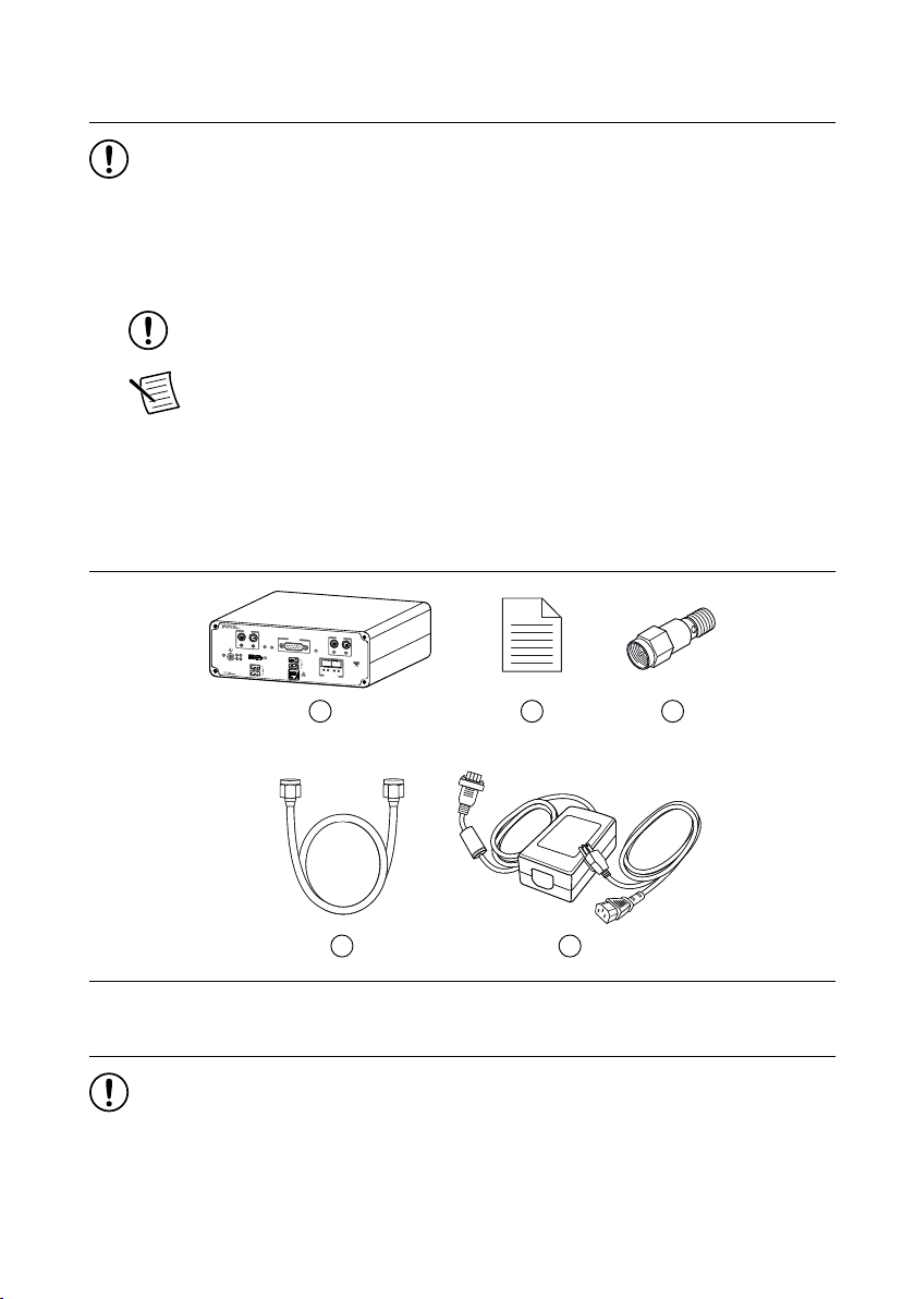
Verifying the Kit Contents
Figure 1. Kit Contents
1. USRP-2974
2. Getting Started Guide (This Document)
3. 30 dB SMA Attenuator
Notice If you directly connect or cable a signal generator to your device, or if you
connect multiple devices together, you must connect a 30 dB attenuator to the RF
input (RX1 or RX2) of each receiving USRP-2974.
2 | ni.com | USRP-2974 Getting Started Guide
4. SMA (m)-to-SMA (m) Cable
5. Power Supply
Page 3
Optional Items
• Additional SMA (m)-to-SMA (m) cables to use the REF IN and PPS IN signals
• 1 G or 10 G Ethernet cable
• CDA-2990 Clock Distribution Device for synchronizing multiple devices
• GPS antenna
• 10 G Ethernet card for desktop
Tip NI recommends using the Ettus 10 Gigabit Ethernet Card for Desktop,
available at www.ettus.com.
Installing the Software
You must be an Administrator to install NI software on your computer.
Ensure that you have installed the latest version of NI Package Manager. To access the
download page for NI Package Manager, go to ni.com/info and enter Info Code
NIPMDownload.
1. Install LabVIEW Communications System Design Suite.
2. Install the latest NI-USRP instrument driver using NI Package Manager.
3. Follow the instructions in the installation prompts.
Note Windows users may see access and security messages during
installation. Accept the prompts to complete the installation.
Connecting to a Computer
For most applications, the USRP-2974 must be connected either to a desktop computer or a
laptop computer.
Install any software you plan to use on the desktop computer or laptop computer before you
connect the hardware.
1. (Optional) Connect any additional attachments required for your project to the front panel
or back panel terminals of the USRP-2974.
2. Connect the USRP-2974 to an Ethernet port on the local subnet or directly to the
computer using an Ethernet cable.
Connection Action
1G ETH Connect the RJ45 connector of the USRP-2974 front panel to the Ethernet
port of the computer.
USRP-2974 Getting Started Guide | © National Instruments | 3
Page 4
Connection Action
10G ETH Connect the SFP+ Port 0 connector of the USRP-2974 front panel to the
Ethernet port of the computer.
Note The USRP-2974 automatically attempts to connect to the network using
dynamic host configuration protocol (DHCP). If DHCP is not available, the
USRP-2974 connects to the network with a link-local IP address with the form
169.254.x.x.
Tip Use an Ethernet router to connect multiple USRP-2974 devices to the
computer.
Related Information
How Do I Change My IP Address Using My Computer? on page 9
Powering on the Device
1. Connect the power supply to the USRP-2974.
2. Plug the power supply into a wall outlet. Press the power button.
3. Power on the computer or laptop.
Programming the Device
You can use the NI-USRP instrument driver to create communications applications for the
USRP-2974.
The USRP-2974 contains a controller that runs NI Linux Real-Time. It also contains a
LabVIEW FPGA target, which supports the creation of custom FPGAs and configuration of
the device using Instrument Design Libraries (IDLs).
NI-USRP Instrument Driver
The NI-USRP instrument driver features a set of functions and properties that exercise the
capabilities of the USRP-2974, including configuration, control, and other device-specific
functions.
Refer to the NI-USRP Manual for information about using the instrument driver in your
applications.
4 | ni.com | USRP-2974 Getting Started Guide
Page 5

Software Options
You must use the USRP RIO IDL when programming the USRP-2974.
Note The NI-USRP API is not supported when programming the USRP-2974.
• Description:
– Allows you to interface with the FPGA of your USRP-2974 for advanced
programming and digital signal processing (DSP).
– Uses the USRP RIO Sample Projects, which allow you to take common
measurements with your device. USRP RIO Sample Projects are included in the
installation.
• Use Case: Use with LabVIEW Communications System Design Suite to customize the
behavior of the device FPGA to create application-specific instrument designs.
• Location:
– (LabVIEW Communications System Design Suite 2.1 to Current) On the Diagram
tab, select Hardware Interfaces»Wireless Design and Test»USRP RIO from the
palette.
– (LabVIEW Communications System Design Suite 2.0) On the Diagram tab, select
Hardware Interfaces»USRP RIO from the palette.
NI-USRP Sample Project
NI-USRP includes a sample project that serves as a starting point to build a USRP RIO
streaming application.
• LabVIEW NXG 2.1 to Current or LabVIEW Communications System Design Suite 2.1
to Current: From the Projects tab, select USRP RIO and choose the applicable sample
project for your device and setup.
• LabVIEW Communications System Design Suite 2.0: From the Projects tab, choose the
applicable sample project for your device and setup.
Using Your Device with Software
You can view and manage your device using SystemLink or LabVIEW Communications
System Design Suite.
Note SystemLink is not supported when using LabVIEW Communications System
Design Suite 2.0.
Related Information
Refer to the SystemLink Manual to learn more about using your device with SystemLink.
Refer to the LabVIEW Communications System Design Suite Manual for information on using
a real-time target, such as connecting to a real-time controller, testing a VI, and deploying and
running an application.
USRP-2974 Getting Started Guide | © National Instruments | 5
Page 6
Adding Hardware to LabVIEW Communications System Design Suite
You must add your USRP-2974 to LabVIEW Communications System Design Suite before
you can use it to run code.
Related Information
Why Can't I Detect My Device in LabVIEW Communications System Design Suite? on page
9
What is the IP Address of My Device? on page 9
Adding Hardware to LabVIEW Communications System Design Suite 2.1 to Current
1. Open LabVIEW Communications System Design Suite and select the Hardware button
to open SystemDesigner.
2. Right-click anywhere in SystemDesigner and select Add hardware. Alternatively, select
the + button.
3. In the Discovered hardware tab, select the USRP-2974 you want to register. Click Add.
Note If your device is not listed in the Discovered hardware tab, open the
Add hardware by address tab and type the IP address or hostname of your
device in the IP address/hostname field. Click Connect.
Note By default, the user name is root, and the password is blank.
4. Click Close.
Adding Hardware to LabVIEW Communications System Design Suite 2.0
1. Open LabVIEW Communications System Design Suite and select the Hardware tab.
2. Select Network Systems to display USRP-2974 devices that you can reserve to use in
projects on the computer.
The device and the computer must be connected to the same local network.
3. In the Unregistered Systems category, select the icon of the USRP-2974 you want to
register.
4. Click Register.
Note If your USRP-2974 does not appear in the Unregistered Systems
category, type the IP address or hostname in the Register by IP or Hostname
field.
5. Add or verify the Hostname or IP Address, User name, and Password.
Note By default, the user name is root, and the password is blank.
6. Click Register.
6 | ni.com | USRP-2974 Getting Started Guide
Page 7

Adding Hardware to SystemLink
Connect your SystemLink Server to a target with LabVIEW Communications Real-Time
Image installed to manage your device.
Note SystemLink Client is automatically installed with the LabVIEW
Communications Real-Time Image.
1. Launch and log in to NI SystemLink Web Application.
2. Click Systems Manager »Discovered Systems . Since SystemLink Client is already
installed on the target, your server automatically detects it.
3. Select the target and click Add Selected to register it as a managed system.
Related Information
For SystemLink Server setup instructions, refer to the SystemLink Manual.
Adding Your Device to a Project
Register your device with SystemLink or LabVIEW Communications System Design Suite
before adding it to a project.
1. In LabVIEW Communications System Design Suite, create a new project or open an
existing sample project.
2. In the SystemDesigner palette, navigate to the location appropriate for your version of
LabVIEW Communications System Design Suite.
Version Step
2.0 Software Defined Radio»USRP RIO»NI USRP-2974
2.1 to Current PC»Devices»Software Defined Radio»USRP RIO»NI USRP-2974
3. Select the NI USRP-2974 target and place it on the diagram.
4. In the Configuration pane, take the action appropriate for your version of LabVIEW
Communications System Design Suite.
Version Step
2.0 Select NI USRP-2974 from the Mapped To dropdown menu.
2.1 to Current Click Hostname to choose a controller that has already been registered
or to change the hostname of your controller.
Note If there is an external USRP RIO device connected to the PCIe x4 port
of the USRP-2974 back panel, you must repeat steps 2 through 4 to map to the
corresponding USRP RIO device in the Configuration pane.
USRP-2974 Getting Started Guide | © National Instruments | 7
Page 8

Verifying the Device Connection
Run Tx and Rx Streaming (Host).gvi to confirm that the device transmits and
receives signals and is connected correctly to the host computer.
1. In LabVIEW Communications System Design Suite, navigate to Projects.
2. Select USRP-2974 Single-Device Streaming. Click Create.
3. Add the USRP-2974 device to the project as described in Adding Your Device to a
Project.
4. Run Tx and Rx Streaming (Host).gvi.
If the device is transmitting and receiving signals, the front panel graphs display
waveform data.
5. Click STOP to conclude the test.
Troubleshooting
If an issue persists after you complete a troubleshooting procedure, contact NI technical
support or visit ni.com/support.
Device Troubleshooting
Should I Update Device Firmware and FPGA Images?
Your device ships with firmware and FPGA images compatible with the NI-USRP driver
software. You may need to update the device for compatibility with the latest version of the
software.
Why Doesn't the Device Power On?
Verify that the power supply is functional by substituting a different adapter.
Network Troubleshooting
Why Doesn't the Device Respond to a Ping (ICMP Echo Request)?
The device should reply to an internet control message protocol (ICMP) echo request.
To ping the device, open a Windows command prompt and enter ping <IP address>,
where <IP address> is the IP address for your USRP device. If you do not receive a
response, verify that the host network interface card is set to a static IP address corresponding
to the same subnet as the IP address of the corresponding device. Also verify that the device IP
address is set properly.
8 | ni.com | USRP-2974 Getting Started Guide
Page 9

Why Can't I Detect My Device in LabVIEW Communications System Design Suite?
Complete one or more of the following options to detect your device in LabVIEW
Communications System Design Suite:
• Ensure that the device is powered on and has a valid IP address.
• Refer to the NI-USRP Readme to verify that your version of the NI-USRP instrument
driver supports the USRP-2974.
• Visit ni.com/info and enter the Info Code bxpsse to access the Provisioning a Real-Time
Controller or USRP Stand-Alone Device for LabVIEW Communications tutorial.
What is the IP Address of My Device?
The device acquires an IP address when connected to the network for the first time. You can
discover this IP address by using Linux commands while connected to the device.
1. Connect the USRP-2974 to a monitor, keyboard, and mouse.
2. Enter your login credentials.
3. Use the Linux command ifconfig to view the IP address for the following Ethernet
ports:
Table 1. Ethernet Port Addressing
Ethernet Port
Addressing
eth0 1G ETH RJ45
eth1 Internal 10G ETH
Port Description
eth2 External SFP+ 1G/10G ETH 0
Note The external SFP+ 1G/10G ETH 1 port does
not have access to the system on module (SoM).
Tip You can limit the results by adding the Ethernet port after the Linux
command ifconfig. For example, the Linux command ifconfig eth0
provides the IP address for the 1G ETH RJ45 port.
How Do I Change My IP Address Using My Computer?
1. Open or create a project including the USRP-2974 as described in Adding Your Device to
a Project.
Note If the device cannot be connected in SystemDesigner due to an incorrect
or unknown IP address, set up a temporary IP address for the device as
described in How Do I Change My IP Address without Using My Computer?.
2. Select Network Adapters on the target in SystemDesigner.
3. Select Configure Network Settings on the Configuration pane.
4. Select the network adapter that you want to change the settings for using the addresses
defined in the following table.
USRP-2974 Getting Started Guide | © National Instruments | 9
Page 10

Table 2. Ethernet Port Addressing
Ethernet Port
Addressing
eth0 1G ETH RJ45
eth1 Internal 10G ETH
eth2 External SFP+ 1G/10G ETH 0
Note The external SFP+ 1G/10G ETH 1 port does
Port Description
not have access to the system on module (SoM).
5. Set the mode.
6. Set the address if the mode is static.
7. Click Apply.
How Do I Change My IP Address without Using My Computer?
1. Connect the USRP-2974 to a monitor, keyboard, and mouse.
2. Enter your login credentials.
3. Use the Linux command ifconfig <Port> <IP Address>, where <Port> is one
of the following Ethernet ports, and <IP Address> is the new IP address.
Table 3. Ethernet Port Addressing
Ethernet Port
Addressing
eth0 1G ETH RJ45
Port Description
eth1 Internal 10G ETH
eth2 External SFP+ 1G/10G ETH 0
Note The external SFP+ 1G/10G ETH 1 port does
not have access to the system on module (SoM).
For example, if you would like to change the IP address of the 1G ETH RJ45 port, use the
Linux command ifconfig eth0 <IP Address>.
Notice This change is lost once the device is turned off. Once the device is
accessible from your computer, change the IP address using your computer as
described in How Do I Change My IP Address Using My Computer? to ensure the IP
address is set indefinitely.
Why Does the Device Not Connect to the Host Interface?
Ensure the connection between the host network interface card and the device cable
connection is valid and both the device and computer are powered on.
10 | ni.com | USRP-2974 Getting Started Guide
Page 11

A lit green LED in the upper left corner of the gigabit Ethernet connection port on the device
TX1 RX1 RX2
RF 0
TX1 RX1 RX2
RF 1
TX OUTPUT MAX +20 dBm, RX INPUT MAX -15 dBm, ALL RF PORTS 50 Ω
AUX I/O
3.3 VDC MAX
GPSPPSREF
PWR
USER 1
USER 2
STATUS
RESET
1 0
1G/10G ETH
SFP+ Ports
10/100/
1000
ACT/
LINK
ACT/
LINK
ACT/
LINK
10GbE10GbE
NI USRP-2974
10 MHz – 6 GHz, GPS-Disciplined Clock (160 MHz BW)
front panel indicates a gigabit Ethernet connection.
Front Panel, Back Panel, and Connectors
Direct Connections to the USRP-2974
The USRP-2974 is an RF instrument that is sensitive to ESD and transients. Ensure you take
the following precautions when making direct connections to the USRP-2974 to avoid
damaging the device.
Notice Apply external signals only while the USRP-2974 is powered on. Applying
external signals while the device is powered off may cause damage.
• Ensure you are properly grounded when manipulating cables or antennas connected to the
USRP-2974 TX 1 RX 1 or RX 2 connector.
• If you are using nonisolated devices, such as a nonisolated RF antenna, ensure the devices
are maintained in a static-free environment.
• If you are using an active device, such as a preamplifier or switch routed to the
USRP-2974 TX 1 RX 1 or RX 2 connector, ensure that the device cannot generate signal
transients greater than the RF and DC specifications of the USRP-2974 TX 1 RX 1 or
RX 2 connector.
USRP-2974 Front Panel, Back Panel, and LEDs
Front Panel
USRP-2974 Getting Started Guide | © National Instruments | 11
Page 12

Table 4. Connector Descriptions
Connector Use
RF 0 TX1 RX1 Input and output terminal for the RF signal. TX1 RX1 is an SMA (f)
connector with an impedance of 50 Ω and is a single-ended input or output
channel.
RX2 Input terminal for the RF signal. RX2 is an SMA (f) connector with an
impedance of 50 Ω and is a single-ended input channel.
AUX I/O General-purpose I/O (GPIO) port. AUX I/O is controlled by the FPGA.
RF 1 TX1 RX1 Input and output terminal for the RF signal. TX1 RX1 is an SMA (f)
connector with an impedance of 50 Ω and is a single-ended input or output
channel.
RX2 Input terminal for the RF signal. RX2 is an SMA (f) connector with an
impedance of 50 Ω and is a single-ended input channel.
DP DisplayPort connector to connect one monitor for your controller.
USB2.0 USB ports that support common USB peripheral devices such as flash
drives, hard drives, keyboards, and mice.
USB3.0 USB ports that support common USB peripheral devices such as flash
drives, hard drives, keyboards, and mice.
1G ETH RJ45 port used for 1G ETH connectivity to other ethernet devices.
μUSB USB port used for UART connectivity to the controller.
1G/10G ETH 0 SFP+ port used for 10G ETH connectivity to other ethernet devices.
Connects to the embedded Linux computer for communication with
LabVIEW RT.
1G/10G ETH 1 SFP+ port used for 1G/10G ETH connectivity to other ethernet devices.
Connects to the FPGA. Not currently supported in LabVIEW
Communications System Design Suite.
12 | ni.com | USRP-2974 Getting Started Guide
Page 13

Table 5. LEDs
LED Description Color State Indication
REF Indicates the status of
the reference signal.
PPS Indicates the pulse
per second (PPS).
GPS Indicates whether the
GPSDO is locked.
OFF — There is no reference
signal, or the device is
not locked to the
reference signal.
Green Blinking The device is not
locked to the reference
signal.
Solid The device is locked
to the reference signal.
OFF — There is no PPS
timing reference
signal, or the device is
not locked to the
reference signal.
Green Blinking The device is locked
to the PPS timing
reference signal.
OFF — There is no GPSDO or
the GPSDO is not
locked.
Green Solid The GPSDO is
locked.
USRP-2974 Getting Started Guide | © National Instruments | 13
Page 14

Table 5. LEDs (Continued)
LED Description Color State Indication
STATUS Indicates the status of
the device.
PWR Indicates the power
status of the device.
10/100/1000 Indicates the speed of
the Gigabit Ethernet
link.
OFF — The device initialized
successfully and is
ready for use.
Red Blinking Hardware error. An
internal power supply
has failed. Check
front-panel I/O
connections for shorts.
Remove any shorts
and cycle power to the
USRP-2974. Contact
NI if the problem
persists.
OFF — The device is powered
off.
Green Solid The device is powered
on.
OFF — No link, or 10 Mbps
link.
Green Solid 100 Mbps link.
Amber Solid 1,000 Mbps link.
ACT/LINK Indicates the Gigabit
Ethernet link activity
or status.
14 | ni.com | USRP-2974 Getting Started Guide
OFF — No link has been
established.
Green Solid A link has been
negotiated.
Blinking Activity on the link.
Page 15

Table 5. LEDs (Continued)
PPS
TRIG
OUT
3.3 V
PPS
TRIG
IN
5 V MAX
GPS
ANT
-15 dBm
MAX
5 V
SYSTEM POWER IN
13
–
16V
150W MAX
Vin Vin GND GND
PCIe x4
REF
OUT
3.3 V
REF
IN
+15 dBm
MAX
LED Description Color State Indication
1G/10G ETH 0 ACT/
LINK
Indicates the status of
the SFP+ port.
10GbE Indicates the status of
the 10G ETH link.
1G/10G ETH 1 10GbE Indicates the status of
the 10G ETH link.
Back Panel
OFF — The link is down.
Green Solid The link is up.
Blinking The link is active
(transmitting and
receiving).
OFF — The 10G ETH link is
down.
Green Solid The 10G ETH link is
up.
OFF — The 10G ETH link is
down.
Green Solid The 10G ETH link is
up.
USRP-2974 Getting Started Guide | © National Instruments | 15
Page 16

Table 6. Connector Descriptions
Connector Use
REF OUT Output terminal for an external reference signal for the LO on the
device. REF OUT is an SMA (f) connector with an impedance of
50 Ω, and it is a single-ended reference output. The output signal at
this connector is 10 MHz at 3.3 V.
REF IN Input terminal for an external reference signal for the LO on the
device. REF IN is an SMA (f) connector with an impedance of 50 Ω,
and it is a single-ended reference input. REF IN accepts a 10 MHz
signal with a minimum input power of 0 dBm (0.632 V pk-pk) and a
maximum input power of 15 dBm (3.56 V pk-pk) for a square wave
or sine wave.
PPS TRIG OUT Output terminal for the PPS timing reference. PPS TRIG OUT is an
SMA (f) connector with an impedance of 50 Ω and is a single-ended
input. The output signal is 0 V to 3.3 V TTL. You can also use this
port as a triggered output (TRIG OUT) that you program with the
PPS Trig Out I/O signal.
PPS TRIG IN Input terminal for PPS timing reference. PPS TRIG IN is an SMA (f)
connector with an impedance of 50 Ω and is a single-ended input
channel. PPS TRIG IN accepts 0 V to 3.3 V TTL and 0 V to 5 V
TTL signals. You can also use this port as a triggered input
(TRIG IN) that you control using NI-USRP software.
GPS ANT Input terminal for the GPS antenna signal. GPS ANT is an SMA (f)
connector with a maximum input power of -15 dBm and an output of
5 V DC to power an active antenna.
Notice Do not terminate the GPS ANT port if you do
not use it.
PCIe x4 Port for a PCI Express Generation 2, x4 bus connection through an
MXI Express four-lane cable. Can be used to connect an external
USRP device or external chassis.
SYSTEM POWER IN Input that accepts a 15 V ± 5%, 10 A external DC power connector.
16 | ni.com | USRP-2974 Getting Started Guide
Page 17

Where to Go Next
EXPLORE LEARN CREATE
DISCOVER
the application development
environment (ADE)
for your application.
about hardware features
or review device
specifications.
custom applications with
an application programming
interface (API).
more about your products through ni.com.
LabVIEW Communications
System Design Suite
Manual
USRP Software Defined
Radio Stand-Alone Device
Manual
USRP-2974 Specifications
NI-USRP Sample
Projects*
NI-USRP Manual
RF Solutions
ni.com/rf
Services
ni.com/services
Updates
ni.com/updates
NI-USRP Instrument Driver
AUX I/O
3.3 VDC MAX
RF 0
RF 1
Designed by Ettus ResearchDesigned by Ettus Research
*This item is also installed with the driver software.
Refer to the following figure for information about other product tasks and associated
resources for those tasks.
Worldwide Support and Services
The NI website is your complete resource for technical support. At ni.com/support, you have
access to everything from troubleshooting and application development self-help resources to
email and phone assistance from NI Application Engineers.
Visit ni.com/services for information about the services NI offers.
Visit ni.com/register to register your NI product. Product registration facilitates technical
support and ensures that you receive important information updates from NI.
NI corporate headquarters is located at 11500 North Mopac Expressway, Austin, Texas,
78759-3504. NI also has offices located around the world. For support in the United States,
create your service request at ni.com/support or dial 1 866 ASK MYNI (275 6964). For
support outside the United States, visit the Worldwide Offices section of ni.com/niglobal to
access the branch office websites, which provide up-to-date contact information.
USRP-2974 Getting Started Guide | © National Instruments | 17
Page 18

Information is subject to change without notice. Refer to the NI Trademarks and Logo Guidelines at ni.com/trademarks for
information on NI trademarks. Other product and company names mentioned herein are trademarks or trade names of their
respective companies. For patents covering NI products/technology, refer to the appropriate location: Help»Patents in your
software, the patents.txt file on your media, or the National Instruments Patent Notice at ni.com/patents. You can find
information about end-user license agreements (EULAs) and third-party legal notices in the readme file for your NI product. Refer
to the Export Compliance Information at ni.com/legal/export-compliance for the NI global trade compliance policy and how
to obtain relevant HTS codes, ECCNs, and other import/export data. NI MAKES NO EXPRESS OR IMPLIED WARRANTIES AS
TO THE ACCURACY OF THE INFORMATION CONTAINED HEREIN AND SHALL NOT BE LIABLE FOR ANY ERRORS. U.S.
Government Customers: The data contained in this manual was developed at private expense and is subject to the applicable
limited rights and restricted data rights as set forth in FAR 52.227-14, DFAR 252.227-7014, and DFAR 252.227-7015.
© 2018—2019 National Instruments. All rights reserved.
377416C-01 May 16, 2019
 Loading...