

Page 1
USER GUIDE AND SPECIFICATIONS
USB-9201/9221
8-Channel, 12-Bit Analog Input Devices
This user guide describes how to use the National Instruments
USB-9201/9221 devices and lists the specifications.
Introduction
This user guide describes how to use the National Instruments
USB-9201/9221. In this document, the USB-9201/9221 with screw
terminal and USB-9201/9221 with DSUB are referred to inclusively as the
USB-9201/9221. For information about installing, configuring, and
programming your system, refer to your system documentation.
The USB-9210/9221 data acquisition device provides a USB interface for
eight channels of 12-bit analog inputs with integrated signal conditioning.
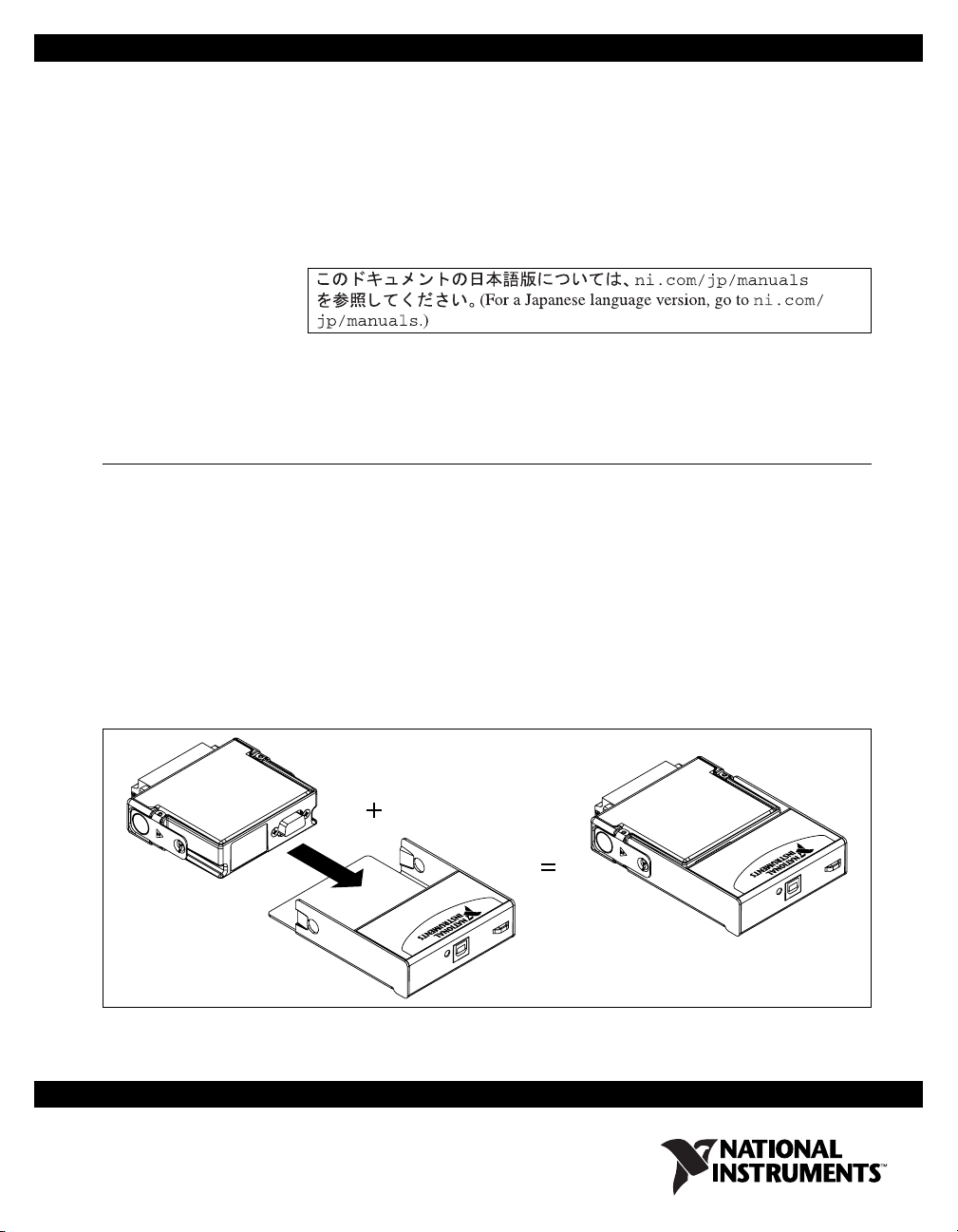
The USB-9201/9211 consists of two components: an NI 9201/9221
module and a USB-9162 carrier, as shown in Figure 1.
NI 9201/9221
USB-9162
Hi-SPeed USB Carrier
NI USB-9162
Figure 1. USB-9201/9221 Components
Hi-Speed USB Carrier
NI USB-9162
USB-9201/9221
Page 2
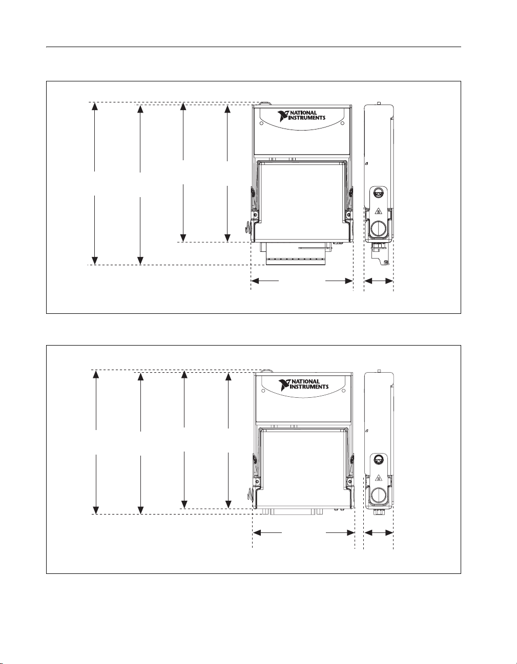
Dimensions
Figures 2 and 3 show the USB-9201/9221 device dimensions.
Hi-Speed USB Carrier
NI USB-9162
140.23 mm
(5.521 in.)
125.76 mm
(4.951 in.)
137.82 mm
(5.426 in.)
123.38 mm
(4.857 in.)
120.68 mm
(4.751 in.)
120.68 mm
(4.751 in.)
118.26 mm
(4.656 in.)
88.12 mm
(3.469 in.)
25.34 mm
(0.998 in.)
Figure 2. USB-9201/9221 Devices in Inches (Millimeters)
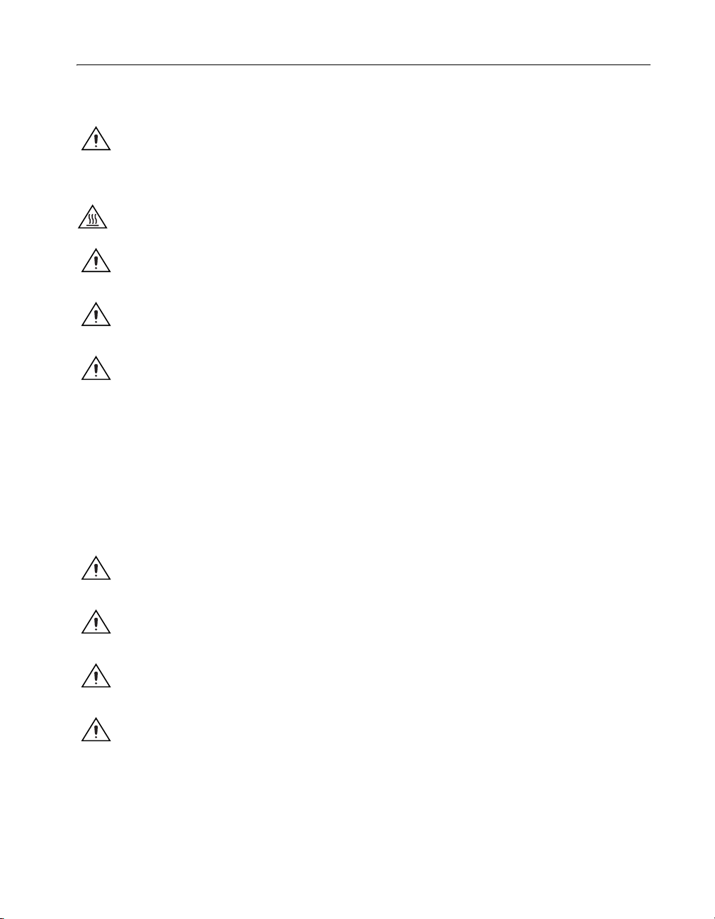
Hi-Speed USB Carrier
NI USB-9162
118.26 mm
(4.656 in.)
88.12 mm
(3.469 in.)
25.34 mm
(0.998 in.)
Figure 3. USB-9201/9221 (DSUB) Devices in Inches (Millimeters)
USB-9201/9221 User Guide and Specifications 2 ni.com
Page 3
Safety Guidelines
Operate the USB-9201/9221 only as described in these operating
instructions.
Caution Although the NI 9201/9221 might have more stringent certification standards
than the USB-9201/9221, when used with the USB-9162 carrier, the combined system
might be limited. Refer to the Specifications section for more information.
Hot Surface This icon denotes that the component may be hot. Touching this component
may result in bodily injury.
Caution Do not disconnect I/O-side wires or connectors unless power has been switched
off or the area is known to be nonhazardous.
Caution Do not remove modules unless power has been switched off and the area is known
to be nonhazardous.
Caution The USB-9201/9221 is not certified for use in hazardous locations.
Safety Guidelines for Hazardous Voltages
You can connect hazardous voltages to the USB-9201/9221 with the screw
terminal only. Do not connect hazardous voltages to the USB-9201/9221
with DSUB.
If hazardous voltages are connected to the module, take the following
precautions. A hazardous voltage is a voltage >42.4 V
or 60 VDC to earth
pk
ground.
Caution Ensure that hazardous voltage wiring is performed only by qualified personnel
adhering to local electrical standards.
Caution Do not mix hazardous voltage circuits and human-accessible circuits on the same
module.
Caution Make sure that devices and circuits connected to the module are properly
insulated from human contact
Caution When module terminals are live with hazardous voltages, make sure that the
terminals are not accessible by using the high voltage screw terminal backshell. Refer to
the Assembling the High Voltage Screw Terminal Backshell section for more information.
© National Instruments Corporation 3 USB-9201/9221 User Guide and Specifications
Page 4

Software
Software support for the USB-9201/9221 is provided by NI-DAQmx.
The NI-DAQmx CD contains example programs that you can use to get
started programming with the USB-9201/9221. Refer to the NI-DAQmx for
USB Devices Getting Started Guide that shipped with your device, and is
also accessible from Start»All Programs»National Instruments»
NI-DAQ, for more information.
Installing the USB-9201/9221
Installing the Software
Before installing the device, you must install the software you plan to use
with the device. Refer to the Software section of this guide and the
NI-DAQmx for USB Devices Getting Started Guide that shipped with your
device, and is also accessible from Start»All Programs»National
Instruments»NI-DAQ, for more information.
Installing the NI 9201/9221 in the USB-9162 Carrier
The NI 9201/9221 module and the USB-9162 carrier are packaged
separately. Refer to Figure 2, while completing the following assembly
steps:
1. Make sure that no signals are connected to the NI 9201/9221 module
and that the USB cable is not connected to the device.
2. Remove the protective cover from the 15-pin DSUB connector.
3. Align the I/O module with the carrier, as shown in Figure 4.
USB-9201/9221 User Guide and Specifications 4 ni.com
Page 5
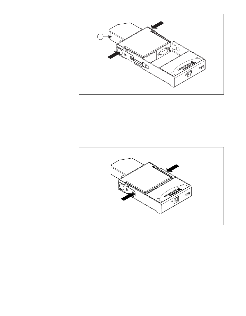
1
1 High Voltage Screw Terminal Backshell
Figure 4. Module Installation
4. Squeeze the latches and insert the NI 9201/9221 module into the
USB-9162 carrier.
5. Press firmly on the connector side of the NI 9201/9221 module until
the latches lock the module into place, as shown in Figure 5.
Figure 5. Locking Module into Place
6. Connect the USB cable to the assembled USB-9201/9221.
© National Instruments Corporation 5 USB-9201/9221 User Guide and Specifications
Page 6

Mounting the USB-9201/9221 to a Panel
Threaded inserts are located in the USB-9201/9221 for mounting it to a
panel. Refer to Figure 6 for dimensions.
85.7 mm
(3.37 in.)
72.2 mm
(2.84 in.)
Figure 6. Module Dimensions
Threaded Insert
M3 x 0.5
8.5 mm (0.34 in.) Max Depth
76.1 mm
(3.00 in.)
Connecting the USB-9201/9221 to a Computer
Plug one end of the USB cable into the USB-9201/9221 and the other end
into an available USB port on the computer. Refer to the NI-DAQmx for
USB Devices Getting Started Guide that shipped with your device, and is
also accessible from Start»All Programs»National Instruments»
NI-DAQ, for more information.
LED Indicator
The LED indicator indicates device status.
Table 1. LED State/Device Status
LED State Device Status
Not lit Device not connected or in suspend.
On, not blinking Device connected, but no module installed.
Single-blink Operating normally.
USB-9201/9221 User Guide and Specifications 6 ni.com
Page 7

Table 1. LED State/Device Status (Continued)
LED State Device Status
Double-blink Connected to USB full speed port. Device
Quadruple-blink Device error. Refer to ni.com/support.
Wiring the USB-9201/9221
The USB-9201/9221 provides connections for eight analog input channels.
The USB-9201/9221 with screw terminal has a 10-terminal, detachable
high voltage screw-terminal backshell. The USB-9201/9221 with DSUB
has a 25-pin DSUB connector.
Each channel has a terminal or pin, AI, to which you can connect a voltage
signal. The USB-9201/9221 also has a common terminal or pin, COM, that
is internally connected to the isolated ground reference of the module.
Refer to Table 2 for the terminal assignments of the USB-9201/9221 with
screw terminal. Refer to Figure 7 for the pin assignments of the
USB-9201/9221 with DSUB.
Caution The high voltage screw terminal backshell must be installed when using
hazardous voltages (>42.4 V
, 60 VDC).
pk
performance might be affected. Refer to the
Specifications section for more information.
© National Instruments Corporation 7 USB-9201/9221 User Guide and Specifications
Page 8

Table 2. Terminal Assignments
Module Terminal Signal
0 AI 0
1 AI 1
2 AI 2
0
1
2
3
4
5
6
7
8
9
3 AI 3
4 AI 4
5 AI 5
6 AI 6
7 AI 7
8 No connection
9 Common (COM)
AI0
NC
AI1
AI2
NC
AI3
AI4
NC
AI5
AI6
NC
AI7
1
14
2
15
3
16
4
17
5
18
6
19
7
20
8
21
9
22
10
23
11
24
12
25
13
COM
NC
COM
COM
NC
COM
COM
NC
COM
COM
NC
COM
COM
Figure 7. Pin Assignments
USB-9201/9221 User Guide and Specifications 8 ni.com
Page 9

Assembling the High Voltage Screw Terminal Backshell
The high voltage screw terminal backshell must be installed when using
hazardous voltages (>42.4 V
completing the following steps:
1. Connect the leads to the screw terminal and secure with the strain
relief.
2. Finish by snapping the backshell around the connector.
, 60 VDC). Refer to Figure 8 while
pk
1
1 Strain Relief
Figure 8. High Voltage Screw Terminal Backshell
Connecting Single-Ended Voltage Signals to the USB-9201/9221
You can connect single-ended voltage signals to the USB-9201/9221.
Connect the positive lead of the voltage signal to AI. Connect the ground
signal to COM.
AI
Voltage
Source
Figure 9. Connecting a Single-Ended Voltage Signal to the USB-9201/9221
© National Instruments Corporation 9 USB-9201/9221 User Guide and Specifications
+
–
COM
USB-9201/9221
Page 10

Refer to your software documentation, accessible from Start»
All Programs»National Instruments»NI-DAQ, for information about
different methods of reading USB-9201/9221 data.
USB-9201/9221 Circuitry
The USB-9201/9221 channels are isolated, and the device protects each
channel from overvoltages. The input signals are scanned, buffered,
conditioned, and then sampled by a single 12-bit ADC. For more
information about overvoltage protection, refer to the Specifications
section.
AI 0
AI 7
Overvoltage
Protection
Mux
Isolated
ADC
Specifications
The following specifications are typical for the range 0 to 60 °C
unless otherwise noted. All voltages are relative to COM unless otherwise
noted.
Input Characteristics
Number of channels................................8
ADC resolution.......................................12 bits
Type of ADC ..........................................Successive approximation
COM
Buffer
USB-9201/9221
Figure 10. Input Circuitry for One Channel
register (SAR)
USB-9201/9221 User Guide and Specifications 10 ni.com
Page 11

Sample rate (aggregate)
1
USB-9201
Single channel.......................... 800 kS/s max
Scanning .................................. 500 kS/s
USB-9221 ....................................... 800 kS/s max
Operating voltage ranges
2
USB-9201 ....................................... ± 10 V (not software selectable)
USB-9221 ....................................... ± 60 V (not software selectable)
Maximum voltage, (AI or COM to earth ground, verified by a dielectric
withstand test)
Screw terminal ................................ 250 V
rms
DSUB.............................................. ±60 VDC
Isolation voltage (AI or COM to earth ground, verified by a dielectric
withstand test)
Screw terminal ................................ 2,300 V
DSUB.............................................. 1,000 V
rms
rms
Overvoltage protection
(AI to COM)........................................... ±100 V
Accuracy
3
Error
Percent of
Reading
Percent of
Range*
USB-9201
Calibrated typ (25 °C, ±5°C) ±0.04% ± 0.07%
Calibrated max (0 to 60 °C) ± 0.25% ± 0.25%
Uncalibrated typ (25 °C, ±5°C) ±0.26% ± 0.46%
Uncalibrated max (0 to 60 °C) ±0.67% ± 1.25%
USB-9221
Calibrated typ (25 °C, ±5°C) ±0.04% ± 0.07%
Calibrated max (0 to 60 °C) ± 0.25% ±0.25%
1
Full performance requires the use of a USB 2.0 high-speed host controller and USB 2.0 hubs.
2
Refer to the Safety section for details about safe operating voltages.
3
Excludes noise.
© National Instruments Corporation 11 USB-9201/9221 User Guide and Specifications
Page 12

Percent of
Error
Uncalibrated typ (25 °C, ±5°C) ±0.26% ± 0.43%
Uncalibrated max (0 to 60 °C) ±0.67% ± 1.06%
* Range equals 10.53 V for the USB-9201, 62.50 V for the USB-9221.
Stability
Offset drift
USB-9201.................................±100 μV/°C
USB-9221.................................±580 μV/°C
Gain drift .........................................±34 ppm/°C
Input bandwidth (–3 dB)
USB-9201........................................690 kHz min
USB-9221........................................950 kHz min
Input impedance
Resistance ........................................1 MΩ
Capacitance......................................5 pF
Input noise (code-centered)
RMS.................................................0.7 LSB
Peak-to-peak....................................5 LSB
Reading
rms
Percent of
Range*
No missing codes....................................12 bits
DNL ........................................................–0.9 to 1.5 LSB
INL..........................................................±1.5 LSB
Crosstalk .................................................–75 dB, 10 kHz
Settling time (to 1 LSB)
USB-9201........................................2 μs
USB-9221........................................1.25 μs
Power Requirements
Power consumption from USB...............500 mA, max
Suspend mode..................................2.5 mA, max
Bus Interface
USB specification ...................................USB 2.0 high speed
USB-9201/9221 User Guide and Specifications 12 ni.com
Page 13

Physical Characteristics
If you need to clean the module, wipe it with a dry towel.
Dimensions
With combicon................................ 14.0 cm × 8.8 cm × 2.5 cm
........................................................ (5.52 in. × 3.47 in. × 1.00 in.)
25-pin DSUB .................................. 12.6 cm × 8.8 cm × 2.5 cm
........................................................ (4.95 in. × 3.47 in. × 1.00 in.)
Screw-terminal wiring............................ 12 to 24 AWG copper conductor
Torque for screw terminals .................... 0.5 – 0.6 N · m (4.4 – 5.3 lb · in.)
Weight
USB-9201/9221 with combicon ..... Approx. 250 g (8.8 oz)
USB-9201/9221 with DSUB .......... Approx. 245 g (8.6 oz)
Safety
Maximum Voltage
Connect only voltages that are within these limits.
wire with 10 mm (0.39 in.) of
insulation stripped from the end
AI to COM ............................................. ±60 VDC
Isolation Voltages for USB-9201/9221 with Screw Termi nals
Channel-to-channel isolation ................. None
Channel-to-earth ground isolation
Continuous ...................................... 250 V
Category II
Withstand ........................................ 2,300 V
dielectric withstand test
Measurement Category II is for measurements performed on circuits
directly connected to the electrical distribution system. This category refers
to local-level electrical distribution, such as that provided by a standard
wall outlet (for example, 115 V for U.S. or 230 V for Europe). Do not use
this module with Measurement Category III or IV voltages.
© National Instruments Corporation 13 USB-9201/9221 User Guide and Specifications
, Measurement
rms
, verified by a
rms
Page 14

Isolation Voltages for USB-9201/9221 with DSUB
Channel-to-channel.................................None
Channel-to-earth ground
Continuous.......................................60 VDC, Measurement
Category I
Withstand.........................................1,000 V
dielectric withstand test
Measurement Category I is for measurements performed on circuits not
directly connected to the electrical distribution system referred to as
MAINS voltage. MAINS is a hazardous live electrical supply system that
powers equipment. This category is for measurements of voltages from
specially protected secondary circuits. Such voltage measurements include
signal levels, special equipment, limited-energy parts of equipment,
circuits powered by regulated low-voltage sources, and electronics. Do not
use this module with Measurement Category II, III, or IV voltages.
, verified by a
rms
Safety Standards
The USB-9201/9221 is designed to meet the requirements of the following
standards of safety for electrical equipment for measurement, control, and
laboratory use:
• EN 61010-1, IEC 61010-1
• UL 61010-1
• CAN/CSA-C22.2 No. 61010-1
Note For UL and other safety certifications, refer to the product label, or visit
ni.com/certification, search by model number or product line, and click the
appropriate link in the Certification column.
Hazardous Locations
The USB-9201/9221 is not certified for use in hazardous locations.
Environmental
The USB-9201/9221 is intended for indoor use only.
Operating temperature
(IEC 60068-2-1, IEC 60068-2-2) ...........0 to 60 °C
Storage temperature
(IEC 60068-2-1, IEC 60068-2-2) ...........– 40 to 85 °C
USB-9201/9221 User Guide and Specifications 14 ni.com
Page 15

Operating humidity
(IEC 60068-2-56)................................... 10 to 90% RH, noncondensing
Storage humidity
(IEC 60068-2-56)................................... 5 to 95% RH, noncondensing
Maximum altitude .................................. 2,000 m
Pollution Degree (IEC 60664) ............... 2
Electromagnetic Compatibility
Emissions ............................................... EN 55011 Class A at 10 m
Immunity................................................ Industrial levels per
EMC/EMI............................................... CE, C-Tick, and FCC Part 15
Note For EMC compliance, operate this device with shielded cabling.
CE Compliance
This product meets the essential requirements of applicable European
Directives, as amended for CE marking, as follows:
FCC Part 15A above 1 GHz
EN 61326-1:1997 + A2:2001,
Table A.1
(Class A) Compliant
Low-Voltage Directive (safety) ............. 73/23/EEC
Electromagnetic Compatibility
Directive (EMC) .................................... 89/336/EEC
Note Refer to the Declaration of Conformity (DoC) for this product for any additional
regulatory compliance information. To obtain the DoC for this product, visit
certification
in the Certification column.
, search by model number or product line, and click the appropriate link
ni.com/
Calibration
You can obtain the calibration certificate for the USB-9201/9221 at
ni.com/calibration.
Calibration interval ................................ 1 year
© National Instruments Corporation 15 USB-9201/9221 User Guide and Specifications
Page 16

Where to Go for Support
The National Instruments Web site is your complete resource for technical
support. At
troubleshooting and application development self-help resources to email
and phone assistance from NI Application Engineers.
National Instruments corporate headquarters is located at
11500 North Mopac Expressway, Austin, Texas, 78759-3504.
National Instruments also has offices located around the world to help
address your support needs. For telephone support in the United States,
create your service request at
instructions or dial 512 795 8248. For telephone support outside the United
States, contact your local branch office:
Australia 1800 300 800, Austria 43 0 662 45 79 90 0,
Belgium32027570020, Brazil551132623599,
Canada 800 433 3488, China 86 21 6555 7838,
Czech Republic 420 224 235 774, Denmark 45 45 76 26 00,
Finland3850972572511, France330148142424,
Germany 49 0 89 741 31 30, India 91 80 41190000,
Israel 972 0 3 6393737, Italy 39 02 413091, Japan 81 3 5472 2970,
Korea820234513400, Lebanon96101332828,
Malaysia 1800 887710, Mexico 01 800 010 0793,
Netherlands 31 0 348 433 466, New Zealand 0800 553 322,
Norway 47 0 66 90 76 60, Poland 48 22 3390150,
Portugal 351 210 311 210, Russia 7 495 783 68 51,
Singapore 1800 226 5886, Slovenia 386 3 425 42 00,
South Africa 27 0 11 805 8197, Spain 34 91 640 0085,
Sweden460858789500, Switzerland41562005151,
Taiwan 886 02 2377 2222, Thailand 662 278 6777,
United Kingdom 44 0 1635 523545
ni.com/support you have access to everything from
ni.com/support and follow the calling
National Instruments, NI, ni.com, and LabVIEW are trademarks of National Instruments Corporation.
Refer to the Terms of Use section on ni.com/legal for more information about National
Instruments trademarks. Other product and company names mentioned herein are trademarks or trad e
names of their respective companies. For patents covering National Instruments products, refer to the
appropriate location: Help»Patents in your software, the patents.txt file on your CD, or
ni.com/patents.
© 2005–2006 National Instruments Corporation. All rights reserved.
371567C-01 Nov06
 Loading...