

Page 1
USER GUIDE
NI USB-622x/625x/628x OEM
M Series USB-6221/6225/6229/6251/6255/6259/6281/6289 OEM Devices
This document provides dimensions, pinouts, and information
about the connectors, switch, LEDs, and chassis ground of the National
Instruments USB-6221 OEM, USB-6225 OEM, USB-6229 OEM,
USB-6251 OEM, USB-6255 OEM, USB-6259 OEM, USB-6281 OEM,
and USB-6289 OEM devices. It also explains how to modify the USB
device name in Microsoft Windows.
Caution There are no product safety, electromagnetic compatibility (EMC), or
CE marking compliance claims made for the USB-622x/625x/628x OEM devices.
Conformity to any and all compliance requirements rests with the end product supplier.
Caution (USB-628x Devices) Exercise caution when placing USB-628x OEM devices inside
an enclosure. Auxiliary cooling may be necessary to keep the device under the maximum
ambient temperature rating of 45 °C, as specified in the NI 628x Specifications.
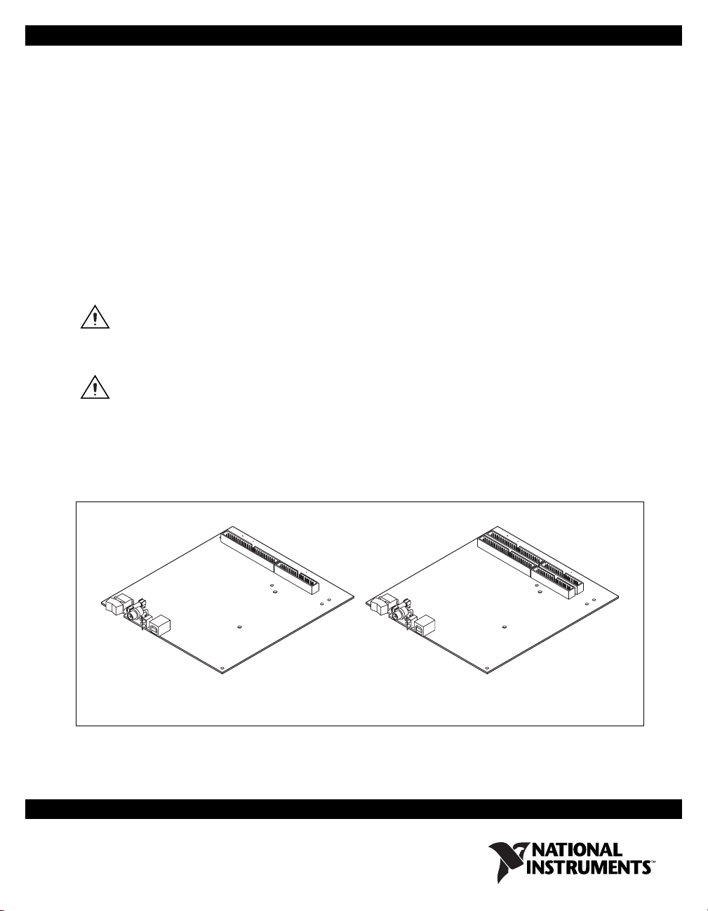
Figure 1 shows the USB-6221/6251/6281 OEM and
USB-6225/6229/6255/6259/6289 OEM devices.
USB-6221/6251/6281 USB-6225/6229/6255/6259/6289
Figure 1. USB-622x/625x/628x OEM Devices
Page 2

Dimensions
Refer to the NI 622x Specifications document for USB-6221/6225/6229
specifications, the NI 625x Specifications document for
USB-6251/6255/6259 specifications, and the NI 628x Specifications
document for USB-6281/6289 specifications. Refer to the M Series User
Manual for more information about USB-622x/625x/628x devices.
You can find all documentation at
Figure 2 shows the dimensions of the USB-6221/6251/6281 OEM device.
ni.com/manuals.
NI USB-622x/625x/628x OEM User Guide 2 ni.com
Page 3

6.950 (176.53)
4x 6.718 (170.63)
6.270 (159.26)
6.140 (155.96)
5.930 (150.62)
0.396 (10.06)
0.304 (7.72)
0.256 (6.50)
0.116 (2.95)
0.000 (0.00)
0.000 (0.00)
0.200 (5.08)
0.918 (23.32)
0.390 (9.91)
3.180 (80.77)
3.730 (94.74)
3.220 (81.79)
3.198 (81.22)
3.734 (94.84)
5.210 (132.33)
6.400 (162.56)
6.013 (152.74)
5.900 (149.86)
4X Ø 0.110 (2.79)
7X Ø 0.125 (3.18)
6.140 (155.96)
5.290 (134.37)
0.304 (7.72)
0.200 (5.08)
0.436 (11.07)
0.392 (9.96)
0.362 (9.19)
0.162 (4.11)
0.062 (1.57)
0.000 (0.00)
0.200 (5.08)
0.393 (9.98)
1.057 (26.85)
0.000 (0.00)
2.072 (52.63)
1.750 (44.45)
2.300 (58.42)
3.296 (83.72)
2.606 (66.19)
3.080 (78.23)
2X Ø 0.140 Cutout
in Panel for LEDs
Ø 0.330 Cutout in Panel
for Power Connector
6.200 (157.48)
0.609 (15.47)
0.515 (13.08)
0.442 (11.23)
6.400 (162.56)
Figure 2. USB-6221/6251/6281 OEM Dimensions in Inches (Millimeters)
© National Instruments Corporation 3 NI USB-622x/625x/628x OEM User Guide
Page 4

Figure 3 shows the dimensions of the USB-6225/6229/6255/6259/6289
OEM device.
6.950 (176.53)
4x 6.718 (170.63)
6.270 (159.26)
6.140 (155.96)
5.930 (150.62)
5.839 (148.31)
5.499 (139.67)
0.396 (10.06)
0.304 (7.72)
0.256 (6.50)
0.116 (2.95)
0.000 (0.00)
0.000 (0.00)
0.200 (5.08)
0.918 (23.32)
0.390 (9.91)
0.200 (5.08)
3.180 (80.77)
3.198 (81.22)
2.072 (52.63)
3.296 (83.72)
3.734 (94.84)
3.730 (94.74)
3.220 (81.79)
6.400 (162.56)
6.013 (152.74)
5.900 (149.86)
5.210 (132.33)
6.200 (157.48)
4X Ø 0.110 (2.79)
7X Ø 0.125 (3.18)
6.140 (155.96)
5.290 (134.37)
0.304 (7.72)
0.200 (5.08)
0.436 (11.07)
0.392 (9.96)
0.362 (9.19)
0.162 (4.11)
0.062 (1.57)
0.000 (0.00)
0.393 (9.98)
1.057 (26.85)
0.000 (0.00)
1.750 (44.45)
2.300 (58.42)
2.606 (66.19)
3.080 (78.23)
2X Ø 0.140 Cutout
in Panel for LEDs
Ø 0.330 Cutout in Panel
for Power Connector
0.609 (15.47)
0.515 (13.08)
0.442 (11.23)
6.400 (162.56)
Figure 3. USB-6225/6229/6255/6259/6289 OEM Dimensions in Inches (Millimeters)
NI USB-622x/625x/628x OEM User Guide 4 ni.com
Page 5

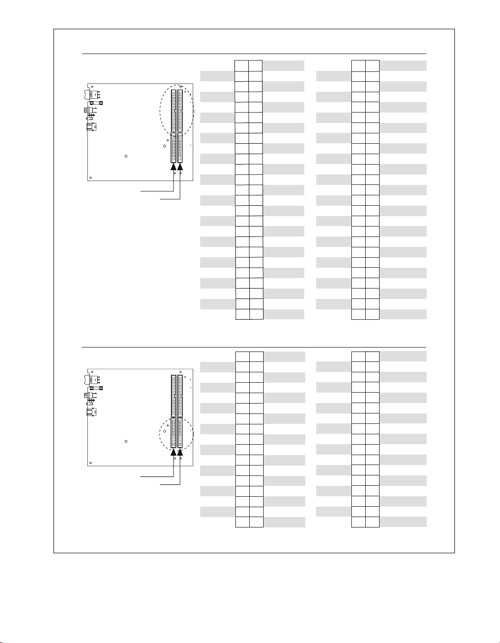
I/O Connector Pinouts
Figures 4 through 9 show the connector pinouts for the USB-6221 OEM,
USB-6225 OEM, USB-6229 OEM, USB-6251 OEM, USB-6255 OEM,
USB-6259 OEM, USB-6281 OEM, and USB-6289 OEM devices.
Refer to the M Series User Manual at
information about USB-622x/625x/628x signals and how to connect them.
ni.com/manuals for more
© National Instruments Corporation 5 NI USB-622x/625x/628x OEM User Guide
Page 6

Bank 0
50-Pin Digital Connector
Bank 0
+5 V
D GND
D GND
D GND
D GND
D GND
D GND
D GND
D GND
D GND
D GND
D GND
D GND
D GND
D GND
D GND
D GND
D GND
D GND
D GND
D GND
D GND
D GND
D GND
D GND
49
50
47
48
45
46
43
44
41
42
39
40
37
38
35
36
33
34
31
32
29
30
27
28
25
26
23
24
21
22
19
20
17
18
15
16
13
14
11
12
10
8
6
4
2
Bank 0
+5 V
PFI 15
PFI 14
PFI 13
PFI 12
PFI 11
PFI 10
PFI 9
PFI 8
PFI 7
PFI 6
PFI 5
PFI 4
PFI 3
PFI 2
PFI 1
PFI 0
P0.7
P0.6
P0.5
9
P0.4
7
P0.3
5
P0.2
3
P0.1
1
P0.0
34-Pin Analog Connector
Bank 0
AI GND
AI 7
AI 14
AI GND
AI 5
AI 12
AI GND
AI 3
AI 10
AI GND
AI 1
AI 8
AI GND
AI GND
AI GND
AO 1
AO 0
34
33
AI 15
32
31
AI GND
30
29
AI 6
28
27
AI 13
26
25
AI GND
24
22
20
18
16
14
12
10
AI 4
23
21
AI 11
19
AI GND
17
AI 2
AI 9
15
AI GND
13
11
AI 0
9
AI SENSE
8
7
NC
6
AO GND
5
4
3
AO GND
2
1
AO GND
NC = No Connect
Figure 4. USB-6221 OEM Connector Pinout
NI USB-622x/625x/628x OEM User Guide 6 ni.com
Page 7
50-Pin Analog/Digital
Connectors
Bank 1
Bank 0
+5 V
D GND
D GND
D GND
D GND
D GND
D GND
D GND
D GND
D GND
D GND
D GND
D GND
D GND
D GND
D GND
D GND
D GND
D GND
D GND
D GND
D GND
D GND
D GND
D GND
Bank 1
49
50
47
48
45
46
43
44
41
42
39
40
37
38
35
36
33
34
31
32
29
30
27
28
25
26
23
24
21
22
19
20
17
18
15
16
13
14
11
12
10
8
5
6
3
4
1
2
Bank 0
+5 V
PFI 15
PFI 14
PFI 13
PFI 12
PFI 11
PFI 10
PFI 9
PFI 8
PFI 7
PFI 6
PFI 5
PFI 4
PFI 3
PFI 2
PFI 1
PFI 0
P0.7
P0.6
P0.5
9
P0.4
7
P0.3
P0.2
P0.1
P0.0
AI 71
AI 78
AI GND
AI 77
AI 68
AI 67
AI 74
AI GND
AI 73
AI 64
AI 55
AI 62
AI GND
AI 61
AI 52
AI 51
AI 58
AI GND
AI 57
AI 48
AI 39
AI 46
AI GND
AI 45
AI 44
50
48
46
44
42
40
38
36
34
32
30
28
26
24
22
20
18
16
14
12
10
AI 79
49
AI 70
47
AI 69
45
AI 76
43
AI GND
41
AI 75
39
AI 66
37
AI 65
35
AI 72
33
AI GND
31
AI 63
29
AI 54
27
AI 53
25
AI 60
23
AI GND
21
AI 59
19
AI 50
17
AI 49
15
AI 56
13
AI GND
11
AI 47
9
AI 38
8
7
AI 37
6
5
AI GND
4
3
AI 36
2
1
Bank 0
34
33
32
31
30
29
28
27
26
25
24
23
22
21
20
19
18
17
16
15
14
13
12
11
10
8
6
4
2
9
7
5
3
1
AI 35
AI 34
AI 41
AI GND
AI 40
AI 23
AI 22
AI 29
AI GND
AI 20
AI 27
AI GND
AI 18
AI 25
AI GND
AI 16
AI SENSE 2
34-Pin Analog Connectors
Bank 1
Bank 0
AI GND
AI 7
AI 14
AI GND
AI 5
AI 12
AI GND
AI 3
AI 10
AI GND
AI 1
AI 8
AI GND
AI GND
AI GND
AO 1
AO 0
Bank 1
34
33
32
31
30
29
28
27
26
25
24
23
22
21
20
19
18
17
16
15
14
13
12
11
10
8
6
4
2
9
7
5
3
1
AI 15
AI GND
AI 6
AI 13
AI GND
AI 4
AI 11
AI GND
AI 2
AI 9
AI GND
AI 0
AI SENSE
NC
AO GND
AO GND
AO GND
AI 43
AI GND
AI 42
AI 33
AI 32
AI 31
AI GND
AI 30
AI 21
AI 28
AI GND
AI 19
AI 26
AI GND
AI 17
AI 24
AI GND
NC = No Connect
Figure 5. USB-6225 OEM Connector Pinout
© National Instruments Corporation 7 NI USB-622x/625x/628x OEM User Guide
Page 8

Bank 1
Bank 0
50-Pin Digital Connectors
Bank 1
Bank 0
+5 V
D GND
D GND
D GND
D GND
D GND
D GND
D GND
D GND
D GND
D GND
D GND
D GND
D GND
D GND
D GND
D GND
D GND
D GND
D GND
D GND
D GND
D GND
D GND
D GND
50
49
48
47
46
45
44
43
42
41
40
39
38
37
36
35
34
33
32
31
30
29
28
27
26
25
24
23
22
21
20
19
18
17
16
15
14
13
12
11
10
8
6
4
2
Bank 1
49
+5 V
P0.31
P0.30
P0.29
P0.28
P0.27
P0.26
P0.25
P0.24
P0.23
P0.22
P0.21
P0.20
P0.19
P0.18
P0.17
P0.16
P0.15
P0.14
P0.13
P0.12
9
P0.11
7
P0.10
5
P0.9
3
P0.8
1
+5 V
D GND
D GND
D GND
D GND
D GND
D GND
D GND
D GND
D GND
D GND
D GND
D GND
D GND
D GND
D GND
D GND
D GND
D GND
D GND
D GND
D GND
D GND
D GND
D GND
50
48
46
44
42
40
38
36
34
32
30
28
26
24
22
20
18
16
14
12
10
+5 V
47
PFI 15
45
PFI 14
43
PFI 13
41
PFI 12
39
PFI 11
37
PFI 10
35
PFI 9
33
PFI 8
31
PFI 7
29
PFI 6
27
PFI 5
25
PFI 4
23
PFI 3
21
PFI 2
19
PFI 1
17
PFI 0
15
P0.7
13
P0.6
11
P0.5
9
P0.4
7
P0.3
8
5
P0.2
6
3
P0.1
4
1
P0.0
2
Bank 0
34-Pin Analog Connectors
Bank 1
Bank 0
AI GND
AI 23
AI 30
AI GND
AI 21
AI 28
AI GND
AI 19
AI 26
AI GND
AI 17
AI 24
AI GND
AI GND
AI GND
AO 3
AO 2
34
33
AI 31
32
31
AI GND
30
29
AI 22
27
8
6
4
2
25
23
21
19
17
15
13
11
9
7
5
3
1
AI 29
AI GND
AI 20
AI 27
AI GND
AI 18
AI 25
AI GND
AI 16
AI SENSE 2
NC
AO GND
AO GND
AO GND
28
26
24
22
20
18
16
14
12
10
AI GND
AI 7
AI 14
AI GND
AI 5
AI 12
AI GND
AI 3
AI 10
AI GND
AI 1
AI 8
AI GND
AI GND
AI GND
AO 1
AO 0
34
32
30
28
26
24
22
20
18
16
14
12
10
AI 15
33
AI GND
31
AI 6
29
AI 13
27
AI GND
25
AI 4
23
AI 11
21
AI GND
19
AI 2
17
AI 9
15
AI GND
13
AI 0
11
AI SENSE
9
8
NC
7
6
AO GND
5
4
AO GND
3
2
AO GND
1
NC = No Connect NC = No Connect
Figure 6. USB-6229 OEM Connector Pinout
NI USB-622x/625x/628x OEM User Guide 8 ni.com
Page 9

Bank 0
50-Pin Digital Connector
Bank 0
+5 V
D GND
D GND
D GND
D GND
D GND
D GND
D GND
D GND
D GND
D GND
D GND
D GND
D GND
D GND
D GND
D GND
D GND
D GND
D GND
D GND
D GND
D GND
D GND
D GND
49
50
47
48
45
46
43
44
41
42
39
40
37
38
35
36
33
34
31
32
29
30
27
28
25
26
23
24
21
22
19
20
17
18
15
16
13
14
11
12
10
8
6
4
2
Bank 0
+5 V
PFI 15
PFI 14
PFI 13
PFI 12
PFI 11
PFI 10
PFI 9
PFI 8
PFI 7
PFI 6
PFI 5
PFI 4
PFI 3
PFI 2
PFI 1
PFI 0
P0.7
P0.6
P0.5
9
P0.4
7
P0.3
5
P0.2
3
P0.1
1
P0.0
34-Pin Analog Connector
Bank 0
AI GND
AI 7
AI 14
AI GND
AI 5
AI 12
AI GND
AI 3
AI 10
AI GND
AI 1
AI 8
AI GND
AI GND
AI GND
AO 1
AO 0
34
33
AI 15
32
31
AI GND
30
29
AI 6
28
27
AI 13
26
25
AI GND
24
22
20
18
16
14
12
10
AI 4
23
21
AI 11
19
AI GND
17
AI 2
AI 9
15
AI GND
13
11
AI 0
9
AI SENSE
8
7
APFI 0
6
AO GND
5
4
3
AO GND
2
1
AO GND
Figure 7. USB-6251/6281 OEM Connector Pinout
© National Instruments Corporation 9 NI USB-622x/625x/628x OEM User Guide
Page 10

50-Pin Analog/Digital
Connectors
Bank 1
Bank 0
+5 V
D GND
D GND
D GND
D GND
D GND
D GND
D GND
D GND
D GND
D GND
D GND
D GND
D GND
D GND
D GND
D GND
D GND
D GND
D GND
D GND
D GND
D GND
D GND
D GND
Bank 1
49
50
47
48
45
46
43
44
41
42
39
40
37
38
35
36
33
34
31
32
29
30
27
28
25
26
23
24
21
22
19
20
17
18
15
16
13
14
11
12
9
10
7
8
5
6
3
4
1
2
+5 V
PFI 15
PFI 14
PFI 13
PFI 12
PFI 11
PFI 10
PFI 9
PFI 8
PFI 7
PFI 6
PFI 5
PFI 4
PFI 3
PFI 2
PFI 1
PFI 0
P0.7
P0.6
P0.5
P0.4
P0.3
P0.2
P0.1
P0.0
AI 71
AI 78
AI GND
AI 77
AI 68
AI 67
AI 74
AI GND
AI 73
AI 64
AI 55
AI 62
AI GND
AI 61
AI 52
AI 51
AI 58
AI GND
AI 57
AI 48
AI 39
AI 46
AI GND
AI 45
AI 44
Bank 0
50
49
48
47
46
45
44
43
42
41
40
39
38
37
36
35
34
33
32
31
30
29
28
27
26
25
24
23
22
21
20
19
18
17
16
15
14
13
12
11
10
8
6
4
2
9
7
5
3
1
AI 79
AI 70
AI 69
AI 76
AI GND
AI 75
AI 66
AI 65
AI 72
AI GND
AI 63
AI 54
AI 53
AI 60
AI GND
AI 59
AI 50
AI 49
AI 56
AI GND
AI 47
AI 38
AI 37
AI GND
AI 36
Bank 0
34
33
32
31
30
29
28
27
26
25
24
23
22
21
20
19
18
17
16
15
14
13
12
11
10
8
6
4
2
AI 35
AI 34
AI 41
AI GND
AI 40
AI 23
AI 22
AI 29
AI GND
AI 20
AI 27
AI GND
9
AI 18
AI 25
7
AI GND
5
3
AI 16
AI SENSE 2
1
34-Pin Analog Connectors
Bank 1
Bank 0
AI GND
AI 7
AI 14
AI GND
AI 5
AI 12
AI GND
AI 3
AI 10
AI GND
AI 1
AI 8
AI GND
AI GND
AI GND
AO 1
AO 0
Bank 1
34
33
32
31
30
29
28
27
26
25
24
23
22
21
20
19
18
17
16
15
14
13
12
11
10
9
8
7
6
5
4
3
2
1
AI 15
AI GND
AI 6
AI 13
AI GND
AI 4
AI 11
AI GND
AI 2
AI 9
AI GND
AI 0
AI SENSE
APFI 0
AO GND
AO GND
AO GND
AI 43
AI GND
AI 42
AI 33
AI 32
AI 31
AI GND
AI 30
AI 21
AI 28
AI GND
AI 19
AI 26
AI GND
AI 17
AI 24
AI GND
Figure 8. USB-6255 OEM Connector Pinout
NI USB-622x/625x/628x OEM User Guide 10 ni.com
Page 11

50-Pin Digital Connectors
Bank 1
Bank 0
+5 V
D GND
D GND
D GND
D GND
D GND
D GND
D GND
D GND
D GND
D GND
D GND
D GND
D GND
D GND
D GND
D GND
D GND
D GND
D GND
D GND
D GND
D GND
D GND
D GND
Bank 1
50
49
48
47
46
45
44
43
42
41
40
39
38
37
36
35
34
33
32
31
30
29
28
27
26
25
24
23
22
21
20
19
18
17
16
15
14
13
12
11
10
9
8
7
6
5
4
3
2
1
+5 V
P0.31
P0.30
P0.29
P0.28
P0.27
P0.26
P0.25
P0.24
P0.23
P0.22
P0.21
P0.20
P0.19
P0.18
P0.17
P0.16
P0.15
P0.14
P0.13
P0.12
P0.11
P0.10
P0.9
P0.8
+5 V
D GND
D GND
D GND
D GND
D GND
D GND
D GND
D GND
D GND
D GND
D GND
D GND
D GND
D GND
D GND
D GND
D GND
D GND
D GND
D GND
D GND
D GND
D GND
D GND
Bank 0
49
50
47
48
45
46
43
44
41
42
39
40
37
38
35
36
33
34
31
32
29
30
27
28
25
26
23
24
21
22
19
20
17
18
15
16
13
14
11
12
9
10
7
8
5
6
3
4
1
2
+5 V
PFI 15
PFI 14
PFI 13
PFI 12
PFI 11
PFI 10
PFI 9
PFI 8
PFI 7
PFI 6
PFI 5
PFI 4
PFI 3
PFI 2
PFI 1
PFI 0
P0.7
P0.6
P0.5
P0.4
P0.3
P0.2
P0.1
P0.0
Bank 0
34
33
32
31
30
29
28
27
26
25
24
23
22
21
20
19
18
17
16
15
14
13
12
11
10
9
8
7
6
5
4
3
2
1
AI 15
AI GND
AI 6
AI 13
AI GND
AI 4
AI 11
AI GND
AI 2
AI 9
AI GND
AI 0
AI SENSE
APFI 0
AO GND
AO GND
AO GND
34-Pin Analog Connectors
Bank 1
Bank 0
AI GND
AI 23
AI 30
AI GND
AI 21
AI 28
AI GND
AI 19
AI 26
AI GND
AI 17
AI 24
AI GND
AI GND
AI GND
AO 3
AO 2
Bank 1
34
33
32
31
30
29
28
27
26
25
24
23
22
21
20
19
18
17
16
15
14
13
12
11
10
9
8
7
6
5
4
3
2
1
AI 31
AI GND
AI 22
AI 29
AI GND
AI 20
AI 27
AI GND
AI 18
AI 25
AI GND
AI 16
AI SENSE 2
APFI 1
AO GND
AO GND
AO GND
AI GND
AI 7
AI 14
AI GND
AI 5
AI 12
AI GND
AI 3
AI 10
AI GND
AI 1
AI 8
AI GND
AI GND
AI GND
AO 1
AO 0
Figure 9. USB-6259/6289 OEM Connector Pinout
© National Instruments Corporation 11 NI USB-622x/625x/628x OEM User Guide
Page 12
Default Counter/Timer Pinouts
By default, NI-DAQmx routes the counter/timer inputs and outputs to the
PFI pins, shown in Table 1.
Counter/Timer Signal Default Terminal Name
CTR 0 SRC PFI 8
CTR 0 GATE PFI 9
CTR 0 AUX PFI 10
CTR 0 OUT PFI 12
CTR 0 A PFI 8
CTR 1 SRC PFI 3
CTR 1 GATE PFI 4
CTR 1 AUX PFI 11
CTR 1 OUT PFI 13
Table 1. NI-DAQmx Default Counter/Timer Pins
CTR 0 Z PFI 9
CTR 0 B PFI 10
CTR 1 A PFI 3
CTR 1 Z PFI 4
CTR 1 B PFI 11
FREQ OUT PFI 14
NI USB-622x/625x/628x OEM User Guide 12 ni.com
Page 13

Attaching External LEDs
USB-622x/625x/628x OEM devices have two LEDs that reflect the device
state. The green READY LED indicates when the device is powered on and
configured as a USB device. The yellow ACTIVE LED indicates USB bus
activity.
Three connectors on the device allow you to connect an external LED
circuit to the device, as shown in Figure 10. To connect an external READY
LED, use E1 as the positive connection (+3.3 V) and E2 as the negative
connection. To connect an external ACTIVE LED, use E1 as the positive
connection and E3 as the negative connection. E1 is current limited with
a 100 Ω resistor to the 3.3 V internal supply. This configuration limits
the current to approximately 16 mA into a single external LED or
approximately 8 mA each when both LEDs are lit. You also can limit this
current further by using external resistors, also shown in Figure 10.
OEM (On-Board)
3.3 V
E3
E2
100 Ω
E1E2E3
E1
External
READY
LED
Figure 10. Schematic for External LED Circuits
© National Instruments Corporation 13 NI USB-622x/625x/628x OEM User Guide
External
ACTIVE
LED
Page 14

Power Switch
The power switch on the USB-622x/625x/628x OEM device powers the
device on and off. Figure 11 shows the pins on the power switch and
circuitry.
100 kΩ
to Ground
100 kΩ
VDC Out
NC NC
Power to
Device
SW1
Switch
123
SW1
2
VDC In
XF1
Outer
Shell
1
3
100 kΩ
J4/J6/J8
XF1
FUSE
J4/J6/J8
Powe r
Connector
Figure 11. Schematic for the Power Switch
Pin 1, VDC In, is connected to VDC through the fuse (reference designator
XF1). The VDC is the voltage provided by the power supply through the
power connector (reference designator J4/J6/J8
1
) and must be 11–30 VDC,
20 W.
Pin 2, VDC Out, provides power to the circuitry on the device. When the
switch is in the On position, the VDC power supply from pin 1 is routed to
pin 2.
Pin 3, 100 kΩ to Ground, connects pin 2 to ground through a 100 kΩ
resistor when the switch is in the Off position.
1
The power connector is designated as J4 on USB-6225/6255 OEM devices, J6 on USB-6221/6229 OEM devices, and J8 on
USB-6251/6259/6281/6289 OEM devices.
NI USB-622x/625x/628x OEM User Guide 14 ni.com
Page 15

Connecting the USB-622x/625x/628x OEM Device to Your Chassis
The USB-622x/625x/628x OEM device includes several plated mounting
holes that are designed for customer grounded connections, as shown in
Figure 12.
Caution Do not use the holes labeled A in Figure 12 as mounting holes.
A
A
A
Do Not Use These
A
as Mounting Holes
Caution (USB-628x Devices)
Mounting Hole Connected
to Chassis Ground
Figure 12. Customer Mounting Holes
(USB-6225/6229/6255/6259/6289 OEM Shown)
Exercise caution when placing USB-628x OEM devices inside
an enclosure. Auxiliary cooling may be necessary to keep the device under the maximum
ambient temperature rating of 45 °C, as specified in the NI 628x Specifications.
© National Instruments Corporation 15 NI USB-622x/625x/628x OEM User Guide
Page 16

Replacing Fuses
USB-622x/625x/628x OEM devices have a replaceable T 2A 250V
(5 × 20 mm) fuse that protects the device from overcurrent through the
power connector.
(USB-628x Devices Only) USB-628x OEM devices also have a replaceable
F 2A 125V fuse that protects the device from overcurrent through the +5 V
terminal(s).
Replacement fuse information can be found in Table 2. To replace a broken
fuse in USB-622x/625x/628x OEM devices, complete the following steps.
1. Power down and unplug the device.
2. Replace the broken fuse while referring to Figure 13 for the fuse
locations.
2
1
1 T 2A 250V (5 x 20 mm) Fuse
2F 2A 125V Fuse on USB-628x OEM Devices
Figure 13. USB-622x/625x/628x OEM Fuse Locations
NI USB-622x/625x/628x OEM User Guide 16 ni.com
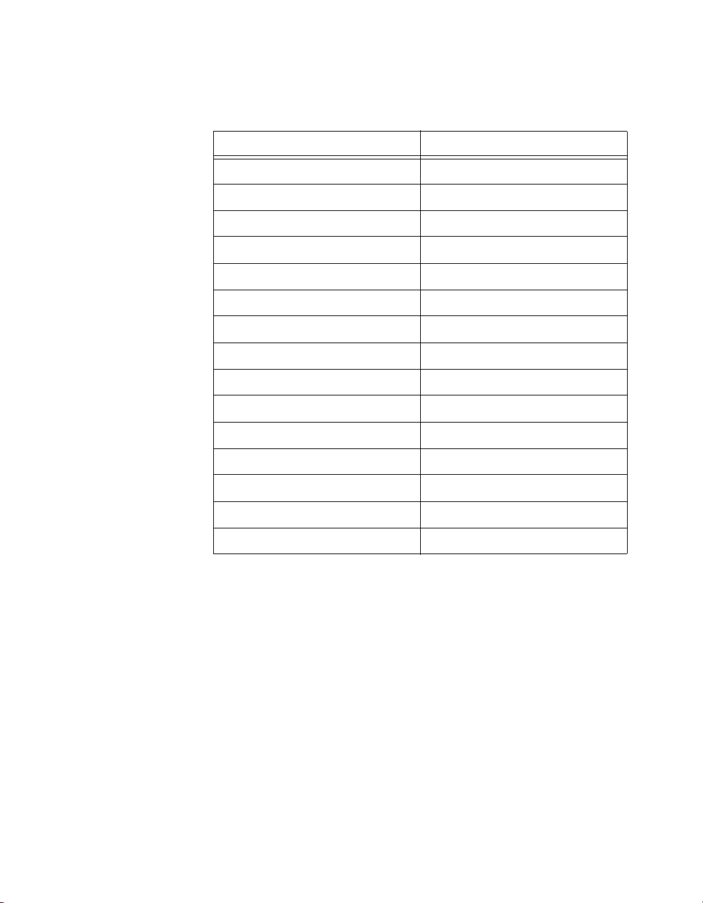
Page 17

Device Components
Table 2 contains information about the components used for interfacing
and interacting with the USB-622x/625x/628x OEM device.
Table 2. USB-622x/625x/628x OEM Components
Manufacturer
Component Reference Designator(s) on PCB Manufacturer
LEDs DS1 Dialight 553-0332
34-pin connectors (USB-6221/6251/6281 OEM) J1 3M N2534-6002RB
(USB-6225/6229/6255/6259/6289
OEM)
J1, J2
50-pin connectors (USB-6221/6251/6281 OEM) P1 3M N2550-6002UB
(USB-6225/6229/6255/6259/6289
OEM)
P1, P2
USB connector J3 AMP 787780-1
Power connector (USB-6221/6229 OEM) J6 Switchcraft 722RA
(USB-6225/6255 OEM) J4
(USB-6251/6259/6281/6289 OEM) J8
Part Number
Power switch SW1 ITT Industries,
E101J1A3QE2
Cannon
T 2A 250V fuse XF1 Littelfuse 218.002XP
F 2A 125V fuse (USB-6281/6289 OEM) F1 Littelfuse 0453002
68-pin
connectors
*
Optional mass termination connectors. These are not populated by default.
© National Instruments Corporation 17 NI USB-622x/625x/628x OEM User Guide
*
(USB-6221 OEM) J8 Honda PCS-E68RLMD1+
(USB-6225/6229/6255 OEM) J7, J8
(USB-6251/6281 OEM) J7
(USB-6259/6289 OEM) J6, J7
Page 18

Modifying the USB Device Name in Microsoft Windows
You can change how the USB-622x/625x/628x OEM device name appears
when users install the device in both the Found New Hardware Wizard that
appears when the device is initially installed and in the Windows Device
Manager.
Windows Vista/XP Users
Figure 14 depicts how a USB-6251 OEM device name appears in the
Found New Hardware Wizard and Windows Device Manager.
Figure 14. USB-6251 OEM Device in the Found New Hardware Wizard and
Device Manager (Windows Vista/XP)
To modify the device name in the Found New Hardware Wizard and
Windows Device Manager in Microsoft Windows Vista/XP, complete the
following steps.
Note You must have NI-DAQmx 8.7 or later installed on your PC.
1. Locate the
where
and
NI USB-622x/625x/628x OEM User Guide 18 ni.com
OEMx.inf file in the y:\WINDOWS\inf\ directory,
x
is the random number assigned to the INF file by Windows,
y
:\ is the root directory where Windows is installed.
Page 19

Note New security updates to Microsoft Vista and NI-DAQ 8.6 or later create random INF
files for NI hardware. Windows assigns random file numbers to all INF files, which causes
the user to search through several INF files until the correct file is located.
If you want to revert back, save a copy of this file as
OEMx_original.inf in a different location.
2. Edit the device INF file by opening
OEMx.inf with a text editor.
At the bottom of this file are the descriptors where Windows looks to
identify the device. Locate the two lines of text that contain in quotes
the descriptors for the device name you are modifying. Change the
descriptor on both lines to the new device name, as shown in Figure 15.
Original File
Modified File
Figure 15. INF File Descriptors Changed to “My Device” (Windows Vista/XP)
3. Save and close the INF file.
4. Go to the Windows Device Manager.
(Windows Vista) In the Device Manager, notice that the OEM device
now appears as
(Windows XP) In the Device Manager, right-click the OEM device under
My Device, as shown in Figure 16.
Data Acquisition Devices, and select Uninstall. Power down the OEM
device and disconnect the USB cable from your PC.
© National Instruments Corporation 19 NI USB-622x/625x/628x OEM User Guide
Page 20

When you reconnect and power on the device, it appears as My Device in
the Found New Hardware Wizard and Windows Device Manager, as shown
in Figure 16.
Note When the device is initially installed, the Windows alert message may display the
following:
Found New Hardware: M Series USB 62xx (OEM). This message appears
for a few seconds until the custom name appears and the Found New Hardware Wizard is
launched. This alert message device name cannot be changed.
Figure 16. “My Device” in the Found New Hardware Wizard and
Device Manager (Windows Vista/XP)
Note Modifying the INF file will not change the USB-622x/625x/628x OEM device name
in Measurement & Automation Explorer (MAX).
NI USB-622x/625x/628x OEM User Guide 20 ni.com
Page 21

Windows 2000 Users
Figure 17 depicts how a USB-6251 OEM device name appears in the
Found New Hardware Wizard and Windows Device Manager.
Figure 17. USB-6251 OEM Device in the Found New Hardware Wizard and
Device Manager (Windows 2000)
To modify the device name in the Found New Hardware Wizard and
Windows Device Manager in Windows 2000, complete the following steps.
Note You must have NI-DAQmx 8.7 or later installed on your PC.
1. Locate the
where
nimioxsu.inf file in the x:\WINNT\inf\ directory,
x
:\ is the root directory where Windows is installed.
If you want to revert back, save a copy of this file as
nimioxsu_original.inf in a different location.
© National Instruments Corporation 21 NI USB-622x/625x/628x OEM User Guide
Page 22

2. Edit the device INF file by opening nimioxsu.inf with a text editor.
At the bottom of this file are the descriptors where Windows looks to
identify the device. Locate the two lines of text that contain in quotes
the descriptors for the device name you are modifying. Change the
descriptor on both lines to the new device name, as shown in Figure 18.
Original File
Modified File
Figure 18. INF File Descriptors Changed to “My Device” (Windows 2000)
3. Save and close the INF file.
4. Go to the Windows Device Manager, right-click the OEM device under
Data Acquisition Devices, and select Uninstall.
5. Power down the OEM device and disconnect the USB cable from
your PC.
NI USB-622x/625x/628x OEM User Guide 22 ni.com
Page 23

When you reconnect and power on the device, it appears as My Device in
the Found New Hardware Wizard and Windows Device Manager, as shown
in Figure 19.
Note When the device is initially installed, the Windows alert message may display the
following:
Found New Hardware: M Series USB 62xx (OEM). This message appears
for a few seconds until the custom name appears and the Found New Hardware Wizard is
launched. This alert message device name cannot be changed.
Figure 19. “My Device” in the Found New Hardware Wizard and
Device Manager (Windows 2000)
Note Modifying the INF file will not change the USB-622x/625x/628x OEM device name
in Measurement & Automation Explorer (MAX).
National Instruments, NI, ni.com, and LabVIEW are trademarks of National Instruments Corporation.
Refer to the Terms of Use section on ni.com/legal for more information about National
Instruments trademarks. Other product and company names mentioned herein are trademarks or trad e
names of their respective companies. For patents covering National Instruments products, refer to the
appropriate location: Help»Patents in your software, the patents.txt file on your media, or
ni.com/patents.
© 2006–2008 National Instruments Corporation. All rights reserved.
371910E-01 Jun08
 Loading...