

Page 1

National Instruments TBX-1303 Manual
Get Pricing & Availability at
ApexWaves.com
Call Today: 1-800-915-6216
Email: sales@apexwaves.com
https://www.apexwaves.com/test-measurement-misc/national-instruments/terminal-blocks/TBX-1303
Page 2

TBX-1303 32-C
HANNELISOTHERMAL
T
ERMINAL
B
LOCKINSTALLATION
This guide describes how to install the National Instruments TBX-1303
32-channel isothermal terminal block and how to use it with SCXI-1100
and SCXI-1102/B/C modules.
The TBX-1303 is a DIN rail-mountable terminal block that connects
through a cable to the SCXI-1100 or SCXI-1102/B/C module input
connector. The TBX-1303 has a high-accuracy thermistor, cold-junction
temperature sensor, and an isothermal copper plane to minimize the
temperature gradients across the screw terminals when you take
measurements with thermocouples. The TBX-1303 mounts on most
European standard DIN EN mounting rails.
The TBX-1303 has 108 screw terminals. Thirty-two sets of three screw
terminals connect to the 32 differential inputs of the SCXI module and
shield each input. One pair of terminals labeled GND connects to the
chassis ground pins of the SCXI module. All the other terminals—AIREF,
AOREF, GUARD, OUT0+, OUT0–, OUT1+, OUT1–, OUTPUT,and
their shields—are reserved for future use.
G
UIDE
National Instruments™, NI™, ni.com™, and SCXI™ are trademarks of National Instruments Corporation. Product and
company names mentioned herein are trademarks or trade names of their respective companies. For patents covering
National Instruments products, refer to the appropriate location: Help»Patents in your software, the patents.txt file
on your CD, or ni.com/patents.
ni.com
© 1996–2002 National Instruments Corp. All rights reserved.
June 2002
371205A-01
Page 3

Conventions
The following conventions are used in this guide:
<> Angle brackets that contain numbers separated by an ellipsis represent
a range of values associated with a bit or signal name—for example,
DBIO<3..0>. Angle brackets can also denote a variable in a channel
name—for example, ACH<i>.
» The » symbol leads you through nested menu items and dialog box options
to a final action. The sequence File»Page Setup»Options directs you to
pull down the File menu, select the Page Setup item, and select Options
from the last dialog box.
This icon denotes a note, which alerts you to important information.
This icon denotes a caution, which advises you of precautions to take to
avoid injury, data loss, or a system crash. When this symbol is marked on
the product, refer to the Read Me First: Safety and Radio-Frequency
Interference document, shipped with the product, for precautions to take.
bold Bold text denotes items that you must select or click in the software, such
as menu items and dialog box options. Bold text also denotes parameter
names and hardware labels.
italic Italic text denotes variables, emphasis, a cross reference, or an introduction
to a key concept. This font also denotes text that is a placeholder for a word
or value that you must supply.
monospace
Text in this font denotes text or characters that you should enter from the
keyboard, sections of code, programming examples, and syntax examples.
This font is also used for the proper names of disk drives, paths, directories,
programs, subprograms, subroutines, device names, functions, operations,
variables, filenames and extensions, and code excerpts.
What You Need to Get Started
To install and use the TBX-1303, you need the following items:
❑
TBX-1303 32-channel isothermal terminal block kit
– TBX-1303 32-channel isothermal terminal block
– TBX-1303 32-Channel Isothermal Terminal Block Installation
Guide
– Four 10 MΩ resistor networks
TBX-1303 32-Channel Isothermal Terminal Block 2 ni.com
– 1/8 in. flathead screwdriver
Page 4

Read Me First: Safety and Radio-Frequency Interference
❑
❑
SCXI chassis and documentation
❑
One of the following modules:
– SCXI-1100 module and documentation
– SCXI-1102/B/C module and documentation
❑
One of the following cable assemblies:
– SH96-96
– R9696
– SBS-96F shielded backshell
❑
Long-nose pliers
❑
3/16 in. wrench
❑
Number 1 Phillips screwdriver
❑
TBX rack-mount kit (optional)
– TBX rack-mount assembly
– TBX Rack-Mount Kit Installation Guide
– Four 10-32 screws
© National Instruments Corporation 3 TBX-1303 32-Channel Isothermal Terminal Block
Page 5
Installing the TBX-1303
Perform the following steps to mount the SH96-96 cable assembly and
connect the TBX-1303 to the SCXI module. Refer to Figures 1 and 2
as needed.
Caution
Refer to the Connecting Signals section before connecting the signals. If signal
wires are connected to the terminal block, dangerous voltages can exist even when the
equipment is powered off.
1. Power off the SCXI chassis.
2. Power off the computer that contains the E Series data acquisition
(DAQ) device, or disconnect the device from the SCXI chassis.
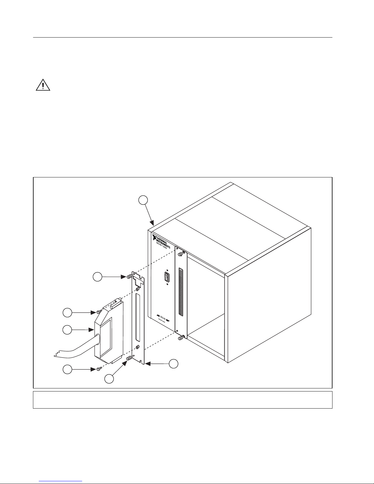
3. Connect the TBX cable adapter to the SCXI module, and secure
the adapter by tightening both thumbscrews.
4
3
1
2
1
3
1 Backshell Mounting Screws
2 SH96-96 Cable
5
3 Thumbscrews
4 SCXI Chassis
Figure 1. Connecting the SH96-96 Cable to the SCXI Module
5 TBX Cable Adapter
TBX-1303 32-Channel Isothermal Terminal Block 4 ni.com
Page 6
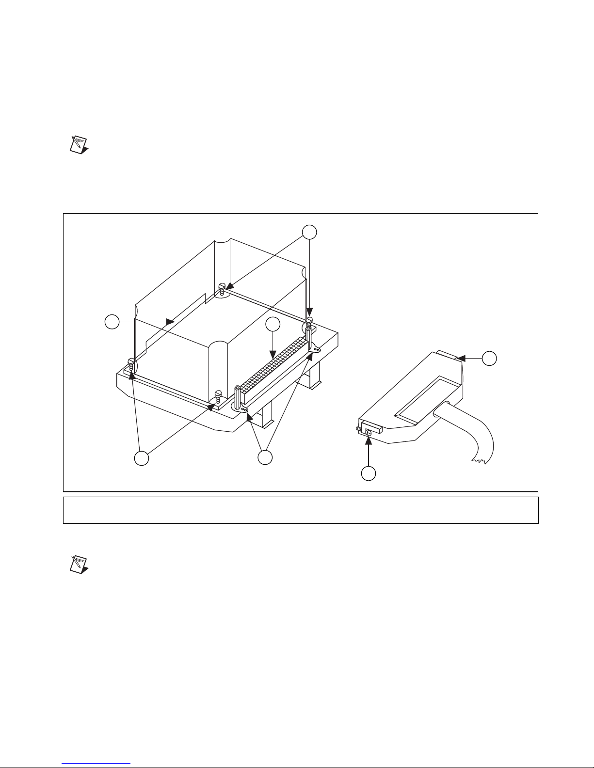
4. Connect either end of the SH96-96 cable to the TBX cable adapter
and SCXI module, and secure the cable by tightening both backshell
mounting screws.
5. Connect the other end of the cable to the TBX-1303 terminal block
connector, and secure the cable by tightening both backshell mounting
screws.
Note
To minimize the temperature gradient inside the terminal block and to maintain its
isothermal properties for accurate cold-junction compensation (CJC), keep the TBX-1303
terminal block away from extreme temperature differentials.
3
5
4
1
3
1 Backshell Mounting Screws
2 Shield Grounding Lugs
Note
The SH96-96 cable is not shown in the exact position for proper connection to the
Figure 2.
2
1
3 Captive Cover Screws
4 Terminal Block Connector
5 Signal Wire Entry
Connecting the SH96-96 Cable to the TBX-1303 Terminal Block
terminal block connector. Refer to Figure 3 for the completed installation.
© National Instruments Corporation 5 TBX-1303 32-Channel Isothermal Terminal Block
Page 7

Rack Mounting
Figure 3. Completed Installation
When you complete the installation, you can mount the TBX assembly on
the rack. If you are using the NI TBX rack-mount assembly, refer to the
TBX Rack-Mount Installation Guide, which you can download from
ni.com/manuals
, for instructions. If you are not using this rack-mount
assembly, complete the following steps to mount the TBX assembly
directly onto the DIN rail.
1. Snap the TBX terminal block onto the DIN rail with a firm push.
2. Install the SCXI chassis using the appropriate chassis rack-mount kit.
Note
To remove the TBX terminal block from the DIN rail, place a flathead screwdriver
into the slot above the terminal block base, and pry it from the rail.
TBX-1303 32-Channel Isothermal Terminal Block 6 ni.com
Page 8

Connecting Signals
Caution
Do not connect hazardous voltage levels (≥42 V) to this product.
To connect field signals to the TBX-1303 for use with the SCXI-1100
or SCXI-1102/B/C module, refer to Figures 2 and 4 as you complete the
following steps.
1. Unscrew the four captive cover screws in the corners of the TBX-1303
terminal block and remove the cover.
2. Connect the signal wires to the screw terminals. Refer to the SCXI
module user manual for examples of how to connect to field signals
and loads. Route the signal wires through the signal wire entry, shown
in Figure 2.
Note
The GND terminals are connected to the SCXI module chassis ground through the
cable, not the shield. In addition, each channel has its own shield terminal (labeled S on the
board) for connecting signal shields. The TBX-1303 has corresponding rows labeled A, B,
and C, as shown in Figure 4, to help you make the correct connections.
3. Verify that you have the resistor networks appropriate to the SCXI
module, signal type, and application. Refer to Table 4 for information
about selecting the appropriate resistor networks.
4. Replace the TBX-1303 terminal block cover and tighten the captive
cover screws.
Note
This terminal block does not provide strain relief for field signal wires. If necessary,
add strain relief, insulation, and padding for the field signal wires.
The installation and signal connection are now complete.
© National Instruments Corporation 7 TBX-1303 32-Channel Isothermal Terminal Block
Page 9

4
5
4
6
3
1
A
B
2
C
1
1 Cover Mounting Nuts
2 Corresponding Rows
3 Product Name
4 Backshell Mounting Nut
5S1Switch
6 Serial Number
Figure 4. TBX-1303 Parts Locator Diagram
7
1
8
9
A
2
1
7 Assembly Number
8 Pull-up Resistors, Pin 1
9 Bias Resistors, Pin 1
Configuring the Temperature Sensor
To enable you to use thermocouples with SCXI modules, the TBX-1303
has a thermistor temperature sensor for CJC.
You can connect the temperature sensor to an SCXI module in one of
two ways:
• Multiplexed temperature sensor (MTEMP) mode—set the TBX-1303
terminal block switch S1 to the MTEMP position. This setting is the
factory default. Refer to Figure 4 for the location of switch S1.
• Direct temperature sensor (DTEMP) mode—set the TBX-1303
terminal block switch S1 to the DTEMP position. This mode connects
the temperature sensor to a separate DAQ channel through the SCXI
module. Refer to the SCXI module user manual to configure the SCXI
module for DTEMP mode.
TBX-1303 32-Channel Isothermal Terminal Block 8 ni.com
Page 10

Table 1 shows the terminal block switch settings.
Table 1. Switch S1 Settings
Switch S1 Position Description
MTEMP mode selected; factory
MTEMP
setting; preferred mode and
parking position
DTEMP
MTEMP
DTEMP
Note
On the SCXI-1102/B/C module, MTEMP mode is the only supported mode.
Temperature Sensor Output and Accuracy
The TBX-1303 temperature sensor voltage output varies from
1.91 to 0.58 V over the 0 to 55 °C temperature range. The temperature
sensor output accuracy is shown in Table 2.
Table 2. Temperature Sensor Voltage Output Accuracy
Temperature Range Voltage Output Accuracy
0to15°C ±1.0 °C
DTEMP mode selected; connects
to a separate DAQ channel
1
1
difference between the temperature sensor and any screw terminal. The temperature sensor
accuracy includes tolerances in all component values, and the effects caused by
temperature, loading, and self-heating.
To select and read the temperature sensor, refer to the driver software
documentation for programming information.
© National Instruments Corporation 9 TBX-1303 32-Channel Isothermal Terminal Block
15 to 35 °C ±0.65 °C
35 to 55 °C ±1.0 °C
Includes the combined effects of the temperature sensor accuracy and the temperature
Page 11

Alternatively, you can follow these steps to convert the cold-junction sensor
voltage to the cold-junction temperature.
1. Calculate the resistance of the thermistor in Ω.
V
TEMPOUT
R
5,000
=
T
--------------------------------------
2.5 V
–
TEMPOUT
Note
V
TEMPOUT
V
TEMPOUT
varies from 1.91 V (at 0 °C) to 0.58 V (at 55 °C). For the best resolution,
= output voltage of the temperature sensor
use the maximum gain for this signal range on the analog input channel of the DAQ device.
The SCXI-1100 does not have a filter on the V
TEMPOUT
signal. Therefore, use an average of
a large number of samples to obtain an accurate measurement. For example, sample for one
second and average. Noisy environments require more samples for greater accuracy.
The SCXI-1102/B/C has a 2 Hz filter on the V
TEMPOUT
signal input channel (MTEMP).
2. Calculate the cold-junction temperature in Kelvin.
T
--------------------------------------------------------------=
K
ab Rln
a = 1.295361 × 10
b = 2.343159 × 10
c = 1.018703 × 10
R
= resistance of the thermistor
T
–3
–4
–7
()cRlnT()
++
1
3
T
3. Convert the temperature to Celsius and Fahrenheit.
T
= temperature in Kelvin
K
T °C() T
T °F()
----------------------- 3 2+=
273.15–=
K
T °C()[]9
5
where T(°F) and T(°C) are the temperature readings in degrees
Fahrenheit and Celsius, respectively.
TBX-1303 32-Channel Isothermal Terminal Block 10 ni.com
Page 12

Temperature Sensor Circuit Diagram
Use the circuit diagram in Figure 5 for optional information and more
details about the TBX-1303 temperature sensor.
+5 V
4.7 k
1%
2.5 V
LM 4040
2.5 V
0.1%
0.1 µF
–t°
2
5k
0.1%
5k
at 25 °C
+
1
10 µF
16 V
2
1
0.1 µF
2
W1
MTEMP
DTEMP
Figure 5.
Temperature Sensor Circuit Diagram
Configuring the Resistor Networks
The TBX-1303 has a pull-up resistor connected between CH+ and +5 V
and has a bias resistor connected between CH– and chassis ground. These
resistors help detect open thermocouples by detecting module amplifier
output saturation. The TBX-1303 ships with 10 Ω and10MΩ resistor
networks. Depending on the SCXI module you use with the TBX-1303,
you might need to change from the default 10 Ω configuration to the 10 MΩ
configuration. Figure 6 shows how the pull-up and bias resistors connect to
the CH± inputs.
© National Instruments Corporation 11 TBX-1303 32-Channel Isothermal Terminal Block
Page 13

+5 V
R
pullup
(RP1, RP2, RP3, RP4)
(in sockets)
CH+
Screw Terminals
CH–
CH+
SCXI Module
CH–
R
bias
(RP5, RP6, RP7, RP8)
(in sockets)
Figure 6. Resistor Connections
A package of four 10 MΩ resistor networks is included in the TBX-1303
kit. You can install these resistor networks as RP5, RP6, RP7, and RP8.
Refer to Figure 4 for placement. With this configuration, thermocouples are
either ground-referenced or floating.
Table 3 shows the relationship between the channel input signals and the
resistor networks.
Table 3. Channel Input Signals and Resistor Networks
Channel
Pull-up Resistor
Network
Bias Resistor
Network
<0..7> RP1 RP5
<8..15> RP2 RP6
<16..23> RP3 RP7
<24..31> RP4 RP8
TBX-1303 32-Channel Isothermal Terminal Block 12 ni.com
Page 14

Table 4 shows which resistor networks to use for the SCXI module, signal
type, and application.
Table 4. Selecting the Appropriate Resistor Networks
Signal
(Floating or
Bias
Module
SCXI-1102/B/C 10 MΩ 10 MΩ Low Both Ye s Recommended
SCXI-1100 10 MΩ 10 MΩ — — — Not
Resistor
10 Ω 10 MΩ Low Floating Ye s Factory-default
10 Ω None High or low Floating No —
None None High or low Ground-referenced No —
10 Ω 10 MΩ Low Floating Ye s Factory-default
Pull-up
Resistor
Source
Impedance
Ground-
Referenced)
Open
Thermocouple
Detection
Comments
configuration
for the
SCXI-1102/B/C
configuration
recommended
configuration
10 Ω None High or low Floating No —
None None High or low Ground-referenced No —
Low source impedance: ≤50
High source impedance: >50
Caution
Ω
Ω
Connecting an external ground-referenced signal with the 10 Ω resistor network
in place can cause permanent damage to the resistor network and the traces on the
TBX-1303 printed circuit board. NI is not liable for any damage or injuries resulting from
improper signal connections.
Detecting Open Thermocouples
To detect an open thermocouple, check whether the corresponding SCXI
module channel is saturated. The pull-up and bias resistors on the
TBX-1303 saturate the channel by applying +5 V at the input of an open
channel, and the positive rail saturates.
SCXI-1102/B/C Module
You can replace the 10 Ω bias resistor networks (factory-default
configuration) in the TBX-1303 with the 10 MΩ resistor networks
supplied in the kit. Using the 10 MΩ resistor networks, you can have
ground-referenced or floating signals. The channels with open
thermocouples saturate at all sample rates of the module.
© National Instruments Corporation 13 TBX-1303 32-Channel Isothermal Terminal Block
Page 15

Use long-nose pliers to remove or replace the resistor networks in the
sockets; be careful not to damage the network package. Make sure pin 1 of
each network is in the correct socket. Refer to Figures 4 and 7 for correct
network placement.
Each network is labeled with descriptive numbers on the left front side,
and pin 1 is located directly beneath the black dot within these numbers.
The 10 Ω resistor network is labeled 10x-1-100 (10 × 10
6
resistor network is labeled 10x-1-106 (10 × 10
Ω). Figure 7 shows
0
Ω); the 10 MΩ
examples of these resistor networks.
Pin 1
10x-1-100
Mfr. code
Pin 1
a. 10 Ω Resistor Network b. 10 MΩ Resistor Network
Figure 7. Resistor Networks
10x-1-106
Mfr. code
SCXI-1100 Module
For the open thermocouple channel to saturate without disturbing the
measurements on any other channel, use an interchannel delay of 200 µs
at a gain of 100 or higher, which corresponds to a sample rate of 5 kHz.
After installing the 10 Ω bias resistors, you can accurately measure at the
maximum sampling rate of the module. The open thermocouple channel
may not saturate if the interchannel delay is less than 200 µs or if the sample
rate is more than 5 kHz at a gain of 100 or higher.
If you want fast open thermocouple detection and you have short
thermocouple leads, or if high accuracy is not important, you can replace
the pull-up resistors with a lower value resistor network. For example,
you can replace the pull-up resistor with a 1 MΩ, 10-pin bused
configuration resistor network (not included) and have a sample rate of
20 kHz (interchannel delay of 50 µs typical). With a 10 Ω bias resistor
network, the current leakage would be 5 µA (5 V ÷ 1MΩ), which can
result in a larger offset error because of thermocouple lead resistance.
Use long-nose pliers to remove or replace the resistor networks in the
sockets; be careful not to damage the network package. Make sure that
pin 1 of each network is in the correct socket. Refer to Figures 4 and 7
for correct network placement.
TBX-1303 32-Channel Isothermal Terminal Block 14 ni.com
Page 16

Errors Due to Open-Thermocouple Detection Circuitry
Open-thermocouple detection circuitry can cause two types of
measurement errors. These errors are the results of common-mode voltage
at the input of the SCXI module and current leakage into the signal leads.
Common-Mode Voltage at the Input of the
SCXI Module
With 10 MΩ pull-up and bias resistors, a common-mode voltage of
2.5 VDC develops if the thermocouple is floating. At a gain of 100, the
common-mode rejection of the SCXI-1102/B/C module is sufficiently high
so that the resulting offset voltage is negligible.
If the application demands extremely high accuracy, you can eliminate this
offset error by calibrating the system. Refer to the module documentation
for more information on calibration. You can also remove the pull-up
resistor, which eliminates the open-thermocouple detection feature, or use
the 10 Ω bias resistor networks, which bring the common-mode voltage
down to nearly 0 VDC.
Current Leakage
The open-thermocouple detection circuitry results in a small current
leakage into the thermocouple. With the 10 MΩ bias and pull-up resistor
networks, the current leakage results in a negligible error. With the
10 Ω bias resistor, the 10 MΩ pull-up resistor connected to 5 VDC causes
a current leakage of approximately 0.5 µA (5 V÷10 MΩ) to flow into the
unbroken thermocouple.
If the thermocouple is lengthy, a voltage drop develops in the thermocouple
because of lead resistance. For example, if you have a 24 AWG J-type
thermocouple that is 20 feet long, a voltage drop of approximately 8 µV can
develop in the thermocouple, which corresponds to an error of 0.18 °C.
The following equation shows how to arrive at the voltage drop value:
(0.145 Ω/ft + 0.658 Ω/ft) × 20 ft × 0.5 µA
If the application demands high accuracy, you can eliminate this error by
removing the appropriate pull-up resistor network or by calibrating the
system offset.
© National Instruments Corporation 15 TBX-1303 32-Channel Isothermal Terminal Block
Page 17

Specifications
Electrical
Physical
All specifications are typical at 25 °C unless otherwise specified.
Cold-junction sensor
Accuracy
Repeatability....................................0.35° from 15 to 35 °C
Output..............................................1.91 (at 0 °C) to 0.58 V (at 55 °C)
Open thermocouple detection
Pull-up resistor.................................10 MΩ
Bias resistor .....................................10 Ω or 10 MΩ
Field wire gauge ..............................26 to 14 AWG
1
........................................0.65° from 15 to 35 °C
1.0° from0to15°Cand
35 to 55 °C
Compatible DIN rails..............................DIN EN 50 022
Terminal block dimensions ....................19.81 by 7.62 by 11.18 cm
Maximum Working Voltage
Maximum working voltage
(signal + common mode) ........................Each input should remain within
DINEN50035
(7.8 by 3 by 4.4 in.)
±10 V of chassis ground
1
Includes the combined effects of the temperature sensor accuracy and the temperature difference between the temperature
sensor and any screw terminal. The temperature sensor accuracy includes tolerances in all component values, the effects
caused by temperature and loading, and self-heating.
TBX-1303 32-Channel Isothermal Terminal Block 16 ni.com
Page 18

Safety
The TBX-1303 was evaluated using the criteria of EN 61010-1 A-2:1995
and meets the requirements of the following standards for safety and
electrical equipment for measurement, control, and laboratory use:
• EN 61010-1:1993/A2:1995, IEC 61010-1:1990/A2:1995
• UL 3101-1:1993, UL 3111-1:1994, UL 3121:1998
• CAN/CSA c22.2 no. 1010.1:1992/A2:1997
Electromagnetic Compatibility
EMC/EMI............................................... CE, C-Tick, and
Electrical emissions................................ EN 55011 Class A at 10 meters
Electrical immunity................................ Evaluated to EN 61236:1998,
FCC Part 15 (Class A) Compliant
FCC Part 15A above 1 GHz
Table 1
Note
In addition, all covers and filler panels must be installed. Refer to the DoC for this product
for any additional regulatory compliance information. To obtain the DoC for this product,
click Declaration of Conformity Information at
site lists the DoCs by product family. Select the appropriate product family, followed by
the product, and a link to the DoC appears in Adobe Acrobat format. Click the Acrobat icon
to download or read the DoC.
For full EMC compliance, you must operate this device with shielded cabling.
ni.com/hardref.nsf/
.ThisWeb
© National Instruments Corporation 17 TBX-1303 32-Channel Isothermal Terminal Block
Page 19

Technical Support Resources
NI Web Support
NI Web support is your first stop for help in solving installation,
configuration, and application problems and questions. Online
problem-solving and diagnostic resources include frequently asked
questions, knowledge bases, product-specific troubleshooting wizards,
manuals, drivers, software updates, and more. Web support is available
through the Technical Support section of
Worldwide Support
NI has offices located around the world to help address your support needs.
You can access our branch office Web sites from the Worldwide Offices
section of
information, support phone numbers, email addresses, and current events.
If you have searched the technical support resources on our Web site
and still cannot find the answers you need, contact your local office or NI
corporate. For telephone support in the United States, dial 512 795 8248.
For telephone support outside the United States, contact your local branch
office:
ni.com
. Branch office Web sites provide up-to-date contact
ni.com
.
Australia 03 9879 5166, Austria 0662 45 79 90 0, Belgium 02 757 00 20,
Brazil 011 3262 3599, Canada (Calgary) 403 274 9391,
Canada (Montreal) 514 288 5722, Canada (Ottawa) 613 233 5949,
Canada (Québec) 514 694 8521, Canada (Toronto) 905 785 0085,
China 86 21 6555 7838, Czech Republic 02 2423 5774,
Denmark 45 76 26 00, Finland 09 725 725 11, France 01 48 14 24 24,
Germany 089 741 31 30, Greece 01 42 96 427, Hong Kong 2645 3186,
India 91 80 4190000, Israel 03 6393737, Italy 02 413091,
Japan 03 5472 2970, Korea 02 3451 3400, Malaysia 603 9596711,
Mexico 001 800 010 0793, Netherlands 0348 433466,
New Zealand 09 914 0488, Norway 32 27 73 00, Poland 22 3390 150,
Portugal 210 311 210, Russia 095 238 7139, Singapore 65 6 226 5886,
Slovenia 3 425 4200, South Africa 11 805 8197, Spain 91 640 0085,
Sweden 08 587 895 00, Switzerland 056 200 51 51,
Taiwan 02 2528 7227, United Kingdom 01635 523545
TBX-1303 32-Channel Isothermal Terminal Block 18 ni.com
 Loading...