

Page 1
INSTALLATION INSTRUCTIONS
NI TB-2641
8 × 64 1-Wire Matrix Terminal Block for the NI PXI-2532
Ρ΅νιϋΠȂུࢊβȜΐ܄ȃ
Introduction
The NI TB-2641 terminal block configures the NI PXI-2532 as an 8 × 64
1-wire matrix. The NI TB-2641 has ribbon cable headers to connect signals
to the switch, and it provides optional isolation resistors to protect the reed
relay from capacitive loads.
Refer to the NI Switches Getting Started Guide to determine when to install
the terminal block.
Make sure you have the following:
• NI TB-2641 terminal block
• 1/8 in. flathead and #1 Phillips screwdrivers
• Eight 2 mm jumpers
• Two 34 conductor, 28 AWG, .050 in. pitch ribbon cable assemblies
(not included)
• One 16 conductor, 28 AWG, .050 in. pitch ribbon cable assembly
(not included)
Note Refer to the Accessories section for information about ordering the appropriate cable
assemblies.
Connecting Ribbon Cables
To connect ribbon cables to the terminal block, refer to Figures 1 and 2
while completing the following steps:
1. Remove the top cover screw.
2. Gently remove the top cover from the terminal block.
Page 2
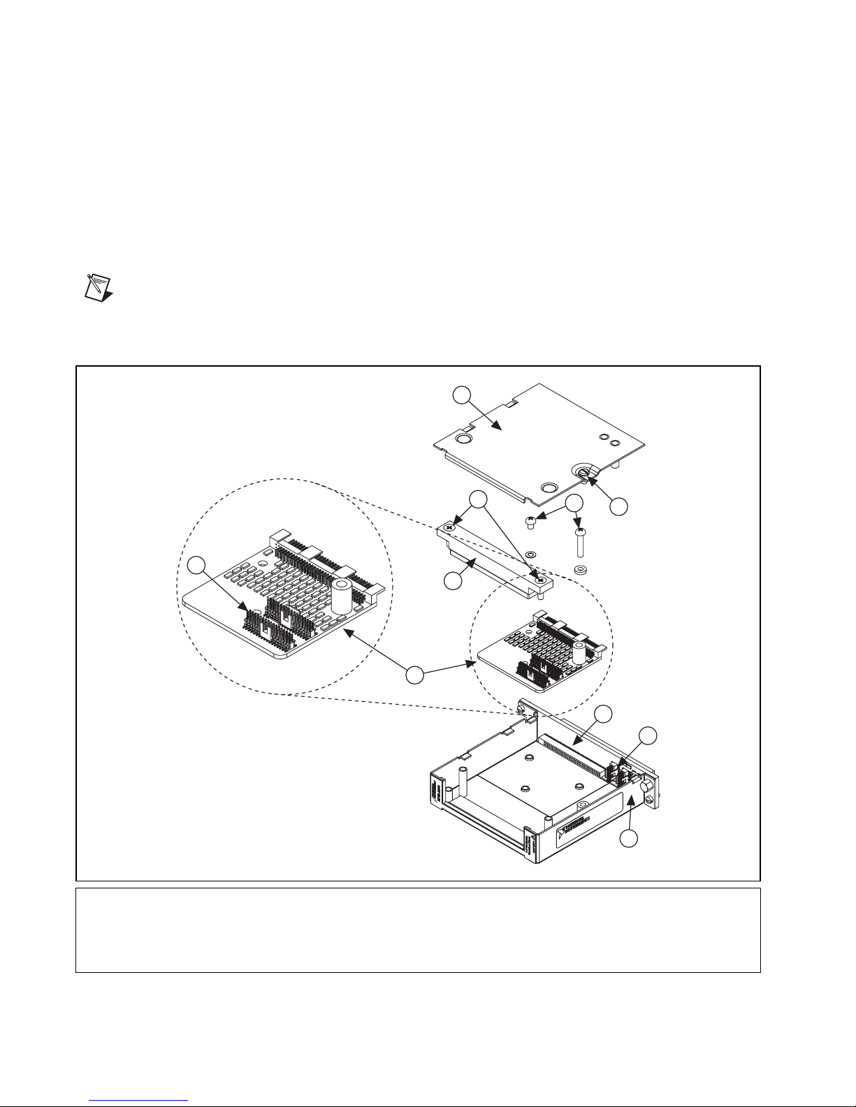
3. Loosen the two screws on the strain-relief assembly and remove the
strain-relief bar.
4. Remove the two screws from the column connection board and retain
the plastic spacer.
5. Disconnect the column connection board from the module interface
board by sliding it toward the front of the terminal block housing.
6. Connect each ribbon cable to the appropriate headers on the column
connection board and the module interface board.
7. Reassemble the terminal block.
Note For information about protection resistance and matrix expansion, refer to the
NI Switches Help.
2
8
1 Top Cover Screw
2 Top Cover
3 Strain-relief Screws
4 Strain-relief Bar
5 Column Connection Board Screws
3
4
6
6 Column Connection Board
7 Module Interface Board
8 Column Headers
9 Row Headers
10 Housing
5
1
7
9
10
NI TB-2641 Installation Instructions 2 ni.com
Figure 1. NI TB-2641 Terminal Block
Page 3

ROW
HEADERS
J2 J3
7
6
5
4
3
2
1
0 (Pin 1)
CONNECTION BOARD
7
5
3
1
ROW
PROTECTION BYPASS
6
4
2
0 (Pin 1)
COLUMN
7
6
5
4
3
2
1
0 (Pin 1)
33
COLUMNS
32
1
0
J2
J3
63
62
31
30
Figure 2. NI TB-2641 Terminal Block Signal Connections
Accessories
Table 1. Accessories for the NI TB-2641
Accessory Manufacturer Part Number
NI SCB-264X screw terminal block National Instruments 779341-01
Row and column cable kit for the
NI SCB-264X terminal blocks
National Instruments 779346-01
Row connection cable for column expansion National Instruments 779325-01
16 Conductor, .05 in. pitch ribbon cable
assemblies
34 Conductor, .05 in. pitch ribbon cable
assemblies
Note For information about using shielded cabling, refer to the NI PXI-2532 Declaration
of Conformity (DoC). To obtain the DoC, visit
model number or product line, and click the appropriate link in the Certification column.
© National Instruments Corporation 3 NI TB-2641 Installation Instructions
Samtec FFSD-08-01-N
Samtec FFSD-17-01-N
ni.com/certification, search by
Page 4

Specifications
This section lists additional specifications for the NI TB-2641 when used
with the NI PXI-2532. All specifications are subject to change without
notice. Visit
Input Characteristics
All input characteristics are DC, ACpk, or a combination unless otherwise
specified.
Maximum switching voltage
Caution This module is rated for Measurement Category I and intended to carry
signal voltages no greater than 100 V. This module can withstand up to 500 V impulse
voltage. Do not use this module for connections to signals or for measurements within
Categories II, III, or IV. Do not connect to MAINs supply circuits (for example, wall
outlets) of 115 or 230 VAC. Refer to the Read Me First: Safety and Electromagnetic
Compatibility document for more information on measurement categories.
ni.com/manuals for the most current specifications.
Channel-to-channel..........................100 V
Channel-to-ground...........................100 V, CAT I
When hazardous voltages (>42.4 V
low-voltage (<42.4 V
/60 VDC) cannot be connected to any other relay terminal.
pk
Maximum current (per channel) .............0.5 A
DC path resistance ..................................<1.5 Ω
Row and column protection
resistors (when used) .............................100 Ω
Bandwidth (–3 dB, 50 Ω termination)
Typical.............................................≥9 MHz
Crosstalk (50 Ω termination)
Channel-to-channel
10 kHz ......................................<–75 dB
100 kHz ....................................<–60 dB
1 MHz.......................................<–40 dB
/60 VDC) are present on any relay terminal, safety
pk
National Instruments, NI, ni.com, and LabVIEW are trademarks of National Instruments Corporation. Refer to the Terms of Use section on
ni.com/legal for more information about National Instruments trademarks. Other product and company names mentioned herein are
trademarks or trade names of their respective companies. For patents covering National Instruments products/technology, refer to the appropriate
location: Help»Patents in your software, the patents.txt file on your media, or the National Instruments Patent Notice at ni.com/patents.
© 2004–2008 National Instruments Corporation. All rights reserved.
373959D Sep08
 Loading...