

Page 1

Artisan Technology Group is your source for quality
new and certied-used/pre-owned equipment
• FAST SHIPPING AND
DELIVERY
• TENS OF THOUSANDS OF
IN-STOCK ITEMS
• EQUIPMENT DEMOS
• HUNDREDS OF
MANUFACTURERS
SUPPORTED
• LEASING/MONTHLY
RENTALS
• ITAR CERTIFIED
SECURE ASSET SOLUTIONS
SERVICE CENTER REPAIRS
Experienced engineers and technicians on staff
at our full-service, in-house repair center
Instra
Remotely inspect equipment before purchasing with
our interactive website at www.instraview.com
Contact us: (888) 88-SOURCE | sales@artisantg.com | www.artisantg.com
SM
REMOTE INSPECTION
View
WE BUY USED EQUIPMENT
Sell your excess, underutilized, and idle used equipment
We also offer credit for buy-backs and trade-ins
www.artisantg.com/WeBuyEquipment
LOOKING FOR MORE INFORMATION?
Visit us on the web at www.artisantg.com for more
information on price quotations, drivers, technical
specications, manuals, and documentation
Page 2

INSTALLATION INSTRUCTIONS
NI TB-2630
Terminal Block for the NI PXI-2530
Ρ΅νιϋΠȂུࢊβȜΐ܄ȃ
This guide describes how to install and connect signals to the
National Instruments TB-2630 terminal block to configure your
NI PXI-2530 switch module as one of the following:
• 128 × 1 1-wire multiplexer
• 64 × 1 2-wire multiplexer
• 32 × 1 4-wire multiplexer
• Eight 16 × 1 1-wire multiplexers
Refer to the NI Switches Getting Started Guide to determine when to install
the terminal block.
Introduction
The TB-2630 terminal block installs in front of the PXI-2530 switch
module. The TB-2630 has ribbon cable headers to connect signals to the
switch. Screw terminals for the trigger input and trigger output signals also
are available.
Conventions
The following conventions are used in this guide:
» The » symbol leads you through nested menu items and dialog box options
to a final action. The sequence File»Page Setup»Options directs you to
pull down the File menu, select the Page Setup item, and select Options
from the last dialog box.
This icon denotes a note, which alerts you to important information.
Artisan Technology Group - Quality Instrumentation ... Guaranteed | (888) 88-SOURCE | www.artisantg.com
Page 3

This icon denotes a caution, which advises you of precautions to take to
avoid injury, data loss, or a system crash.
bold Bold text denotes items that you must select or click in the software, such
as menu items and dialog box options. Bold text also denotes parameter
names.
italic Italic text denotes variables, emphasis, a cross reference, or an introduction
to a key concept. This font also denotes text that is a placeholder for a word
or value that you must supply.
monospace Text in this font denotes text or characters that you should enter from the
keyboard, sections of code, programming examples, and syntax examples.
This font is also used for the proper names of disk drives, paths, directories,
programs, subprograms, subroutines, device names, functions, operations,
variables, filenames, and extensions.
1. Unpack the Terminal Block
To avoid damage when you handle the terminal block, take the following
precautions:
Caution Never touch the exposed pins of connectors.
• Ground yourself using a grounding strap or by touching a grounded
object.
• Touch the antistatic package to a metal part of the chassis before you
remove the terminal block from the package.
Remove the terminal block from the package and inspect the terminal block
for loose components or any sign of damage. Notify NI if the terminal
block appears damaged in any way. Do not install a damaged terminal
block on a switch terminal block.
Store the terminal block in the antistatic package when not in use.
NI TB-2630 Installation Instructions 2 ni.com
Artisan Technology Group - Quality Instrumentation ... Guaranteed | (888) 88-SOURCE | www.artisantg.com
Page 4

2. Verify the Components
Make sure you have the following:
❑ NI TB-2630 terminal block
❑ PXI chassis
❑ NI PXI-2530 switch module
❑ 1/8 in. flathead screwdriver
❑ Eight 2 × 9, 0.100 in. pitch ribbon cable connectors (included)
❑ 18-conductor, 28 AWG, 0.050 in. pitch ribbon cable (not included)
3. Connect Signals
To connect signals to the terminal block, complete the following steps:
1. Remove the terminal block top cover screws with the flathead
screwdriver.
2. Gently lift the terminal block top cover off the terminal block.
3. Loosen the two screws on the strain-relief assembly and remove
the top strain-relief bar.
4. Prepare your ribbon cable by installing the 2 × 9 ribbon cable
connectors onto separate 18-conductor ribbon cables.
5. Connect each ribbon cable to a header.
6. Replace the strain-relief bar and tighten the two screws on the
strain-relief assembly to secure the cables.
7. Replace the terminal block top cover.
8. Secure the terminal block top cover with the top cover screws.
© National Instruments Corporation 3 NI TB-2630 Installation Instructions
Artisan Technology Group - Quality Instrumentation ... Guaranteed | (888) 88-SOURCE | www.artisantg.com
Page 5
8
7
8
9
10
1
2
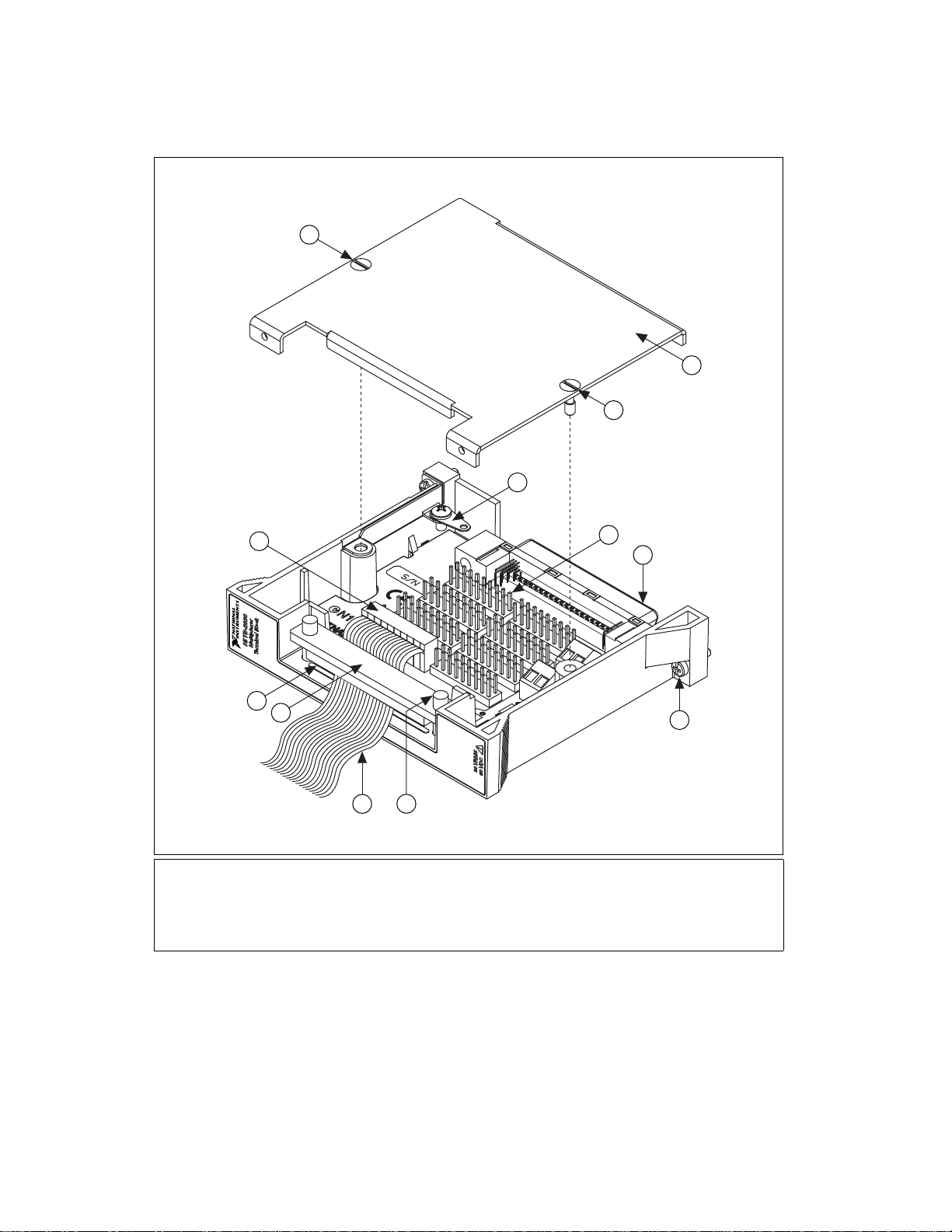
1 Strain-Relief Opening
2 Strain-Relief Bar
3 Ribbon Cable
4 Strain-Relief Screw
5 Chassis Screws
6 Rear Connector
11
6
5
4
3
7 Terminal Block Top Cover
8 Top Cover Screws
9 Safety Ground Lug
10 Ribbon Cable Connector
11 Ribbon Cable Header
Figure 1. TB-2630 Terminal Block
NI TB-2630 Installation Instructions 4 ni.com
Artisan Technology Group - Quality Instrumentation ... Guaranteed | (888) 88-SOURCE | www.artisantg.com
Page 6

BANK 0
1
BANK 1
1
2
BANK 2
1
2
2
BANK 3
1
2
17 18
COM 0 COM 1 COM 2 COM 3
1WREF0 1WREF1
BANK 4
1
17 18
USE SHIELDED
CABLE ON TRIGGERS
2
COM 4 COM 5 COM 6 COM 7
1WREF2 1WREF3
TRIGOUT
17 18
BANK 5
1
17 18
GND
17 18
2
17 18
BANK 6
1
2
17 18
BANK 7
1
2
17 18
TRIGIN
GND
Figure 2. TB-2630 Terminal Block Signal Connections
176 POSITION CONNECTOR
© National Instruments Corporation 5 NI TB-2630 Installation Instructions
Artisan Technology Group - Quality Instrumentation ... Guaranteed | (888) 88-SOURCE | www.artisantg.com
Page 7

Table 1. 128 x 1, 1-Wire Topology Terminal Mapping
Software
Name
com0 BANK 0, PIN 18 ch42 BANK 2, PIN 11 ch85 BANK 5, PIN 6
ch0 BANK 0, PI N 1 ch43 BANK 2, PIN 12 ch86 BANK 5, PIN 7
ch1 BANK 0, PI N 2 ch44 BANK 2, PIN 13 ch87 BANK 5, PIN 8
ch2 BANK 0, PI N 3 ch45 BANK 2, PIN 14 ch88 BANK 5, PIN 9
ch3 BANK 0, PI N 4 ch46 BANK 2, PIN 15 ch89 BANK 5, PIN 10
ch4 BANK 0, PI N 5 ch47 BANK 2, PIN 16 ch90 BANK 5, PIN 11
ch5 BANK 0, PI N 6 ch48 BANK 3, PI N 1 ch91 BANK 5, PIN 12
ch6 BANK 0, PI N 7 ch49 BANK 3, PI N 2 ch92 BANK 5, PIN 13
ch7 BANK 0, PI N 8 ch50 BANK 3, PI N 3 ch93 BANK 5, PIN 14
ch8 BANK 0, PI N 9 ch51 BANK 3, PI N 4 ch94 BANK 5, PIN 15
ch9 BANK 0, PIN 10 ch52 BANK 3, PI N 5 ch95 BANK 5, PIN 16
ch10 BANK 0, PIN 11 ch53 BANK 3, PIN 6 ch96 BANK 6, PIN 1
ch11 BANK 0, PIN 12 ch54 BANK 3, PIN 7 ch97 BANK 6, PIN 2
ch12 BANK 0, PIN 13 ch55 BANK 3, PIN 8 ch98 BANK 6, PIN 3
ch13 BANK 0, PIN 14 ch56 BANK 3, PIN 9 ch99 BANK 6, PIN 4
ch14 BANK 0, PIN 15 ch57 BANK 3, PIN 10 ch100 BANK 6, PIN 5
ch15 BANK 0, PIN 16 ch58 BANK 3, PIN 11 ch101 BANK 6, PIN 6
ch16 BANK 1, PIN 1 ch59 BANK 3, PIN 12 ch102 BANK 6, PIN 7
Hardware Name
Software
Name
Hardware Name
Software
Name
Hardware Name
ch17 BANK 1, PIN 2 ch60 BANK 3, PIN 13 ch103 BANK 6, PIN 8
ch18 BANK 1, PIN 3 ch61 BANK 3, PIN 14 ch104 BANK 6, PIN 9
ch19 BANK 1, PIN 4 ch62 BANK 3, PIN 15 ch105 BANK 6, PIN 10
ch20 BANK 1, PIN 5 ch63 BANK 3, PIN 16 ch106 BANK 6, PIN 11
ch21 BANK 1, PIN 6 ch64 BANK 4, PIN 1 ch107 BANK 6, PIN 12
ch22 BANK 1, PIN 7 ch65 BANK 4, PIN 2 ch108 BANK 6, PIN 13
ch23 BANK 1, PIN 8 ch66 BANK 4, PIN 3 ch109 BANK 6, PIN 14
ch24 BANK 1, PIN 9 ch67 BANK 4, PIN 4 ch110 BANK 6, PIN 15
ch25 BANK 1, PIN 10 ch68 BANK 4, PIN 5 ch111 BANK 6, PIN 16
ch26 BANK 1, PIN 11 ch69 BANK 4, PIN 6 ch112 BANK 7, PIN 1
ch27 BANK 1, PIN 12 ch70 BANK 4, PIN 7 ch113 BANK 7, PIN 2
ch28 BANK 1, PIN 13 ch71 BANK 4, PIN 8 ch114 BANK 7, PIN 3
NI TB-2630 Installation Instructions 6 ni.com
Artisan Technology Group - Quality Instrumentation ... Guaranteed | (888) 88-SOURCE | www.artisantg.com
Page 8

Table 1. 128 x 1, 1-Wire Topology Terminal Mapping (Continued)
Software
Name
ch29 BANK 1, PIN 14 ch72 BANK 4, PIN 9 ch115 BANK 7, PIN 4
ch30 BANK 1, PIN 15 ch73 BANK 4, PIN 10 ch116 BANK 7, PIN 5
ch31 BANK 1, PIN 16 ch74 BANK 4, PIN 11 ch117 BANK 7, PIN 6
ch32 BANK 2, PIN 1 ch75 BANK 4, PIN 12 ch118 BANK 7, PIN 7
ch33 BANK 2, PIN 2 ch76 BANK 4, PIN 13 ch119 BANK 7, PIN 8
ch34 BANK 2, PIN 3 ch77 BANK 4, PIN 14 ch120 BANK 7, PIN 9
ch35 BANK 2, PIN 4 ch78 BANK 4, PIN 15 ch121 BANK 7, PIN 10
ch36 BANK 2, PIN 5 ch79 BANK 4, PIN 16 ch122 BANK 7, PIN 11
ch37 BANK 2, PIN 6 ch80 BANK 5, PIN 1 ch123 BANK 7, PIN 12
ch38 BANK 2, PIN 7 ch81 BANK 5, PIN 2 ch124 BANK 7, PIN 13
ch39 BANK 2, PIN 8 ch82 BANK 5, PIN 3 ch125 BANK 7, PIN 14
ch40 BANK 2, PIN 9 ch83 BANK 5, PIN 4 ch126 BANK 7, PIN 15
ch41 BANK 2, PIN 10 ch84 BANK 5, PIN 5 ch127 BANK 7, PIN 16
Hardware Name
Software
Name
Hardware Name
Software
Name
Hardware Name
Note In the 128 × 1, 1-wire topology, 1WREF0 (BANK 0–1, PIN 17) is connected to
COM1 (BANK 1, PIN 18).
© National Instruments Corporation 7 NI TB-2630 Installation Instructions
Artisan Technology Group - Quality Instrumentation ... Guaranteed | (888) 88-SOURCE | www.artisantg.com
Page 9

Table 2. 64 x 1, 2-Wire Topology Terminal Mapping
Software
Name
com0 BANK 0, PIN 18 BANK 1, PIN 18 ch32 BANK 4, PIN 1 BANK 5, PI N 1
ch0 BANK 0, PI N 1 BANK 1, PIN 1 ch33 BANK 4, PIN 2 BANK 5, PIN 2
ch1 BANK 0, PI N 2 BANK 1, PIN 2 ch34 BANK 4, PIN 3 BANK 5, PIN 3
ch2 BANK 0, PI N 3 BANK 1, PIN 3 ch35 BANK 4, PIN 4 BANK 5, PIN 4
ch3 BANK 0, PI N 4 BANK 1, PIN 4 ch36 BANK 4, PIN 5 BANK 5, PIN 5
ch4 BANK 0, PI N 5 BANK 1, PIN 5 ch37 BANK 4, PIN 6 BANK 5, PIN 6
ch5 BANK 0, PI N 6 BANK 1, PIN 6 ch38 BANK 4, PIN 7 BANK 5, PIN 7
ch6 BANK 0, PI N 7 BANK 1, PIN 7 ch39 BANK 4, PIN 8 BANK 5, PIN 8
ch7 BANK 0, PI N 8 BANK 1, PIN 8 ch40 BANK 4, PIN 9 BANK 5, PIN 9
ch8 BANK 0, PI N 9 BANK 1, PIN 9 ch41 BANK 4, PIN 10 BANK 5, PIN 10
ch9 BANK 0, PIN 10 BANK 1, PIN 10 ch42 BANK 4, PIN 11 BANK 5, PIN 11
ch10 BANK 0, PIN 11 BANK 1, PIN 11 ch43 BANK 4, PIN 12 BANK 5, PIN 12
ch11 BANK 0, PIN 12 BANK 1, PIN 12 ch44 BANK 4, PIN 13 BANK 5, PIN 13
ch12 BANK 0, PIN 13 BANK 1, PIN 13 ch45 BANK 4, PIN 14 BANK 5, PIN 14
ch13 BANK 0, PIN 14 BANK 1, PIN 14 ch46 BANK 4, PIN 15 BANK 5, PIN 15
ch14 BANK 0, PIN 15 BANK 1, PIN 15 ch47 BANK 4, PIN 16 BANK 5, PIN 16
Hardware Name
+ – + –
Software
Name
Hardware Name
ch15 BANK 0, PIN 16 BANK 1, PIN 16 ch48 BANK 6, PIN 1 BANK 7, PIN 1
ch16 BANK 2, PIN 1 BANK 3, PIN 1 ch49 BANK 6, PIN 2 BANK 7, PIN 2
ch17 BANK 2, PIN 2 BANK 3, PIN 2 ch50 BANK 6, PIN 3 BANK 7, PIN 3
ch18 BANK 2, PIN 3 BANK 3, PIN 3 ch51 BANK 6, PIN 4 BANK 7, PIN 4
ch19 BANK 2, PIN 4 BANK 3, PIN 4 ch52 BANK 6, PIN 5 BANK 7, PIN 5
ch20 BANK 2, PIN 5 BANK 3, PIN 5 ch53 BANK 6, PIN 6 BANK 7, PIN 6
ch21 BANK 2, PIN 6 BANK 3, PIN 6 ch54 BANK 6, PIN 7 BANK 7, PIN 7
ch22 BANK 2, PIN 7 BANK 3, PIN 7 ch55 BANK 6, PIN 8 BANK 7, PIN 8
ch23 BANK 2, PIN 8 BANK 3, PIN 8 ch56 BANK 6, PIN 9 BANK 7, PIN 9
ch24 BANK 2, PIN 9 BANK 3, PIN 9 ch57 BANK 6, PIN 10 BANK 7, PIN 10
ch25 BANK 2, PIN 10 BANK 3, PIN 10 ch58 BANK 6, PIN 11 BANK 7, PIN 11
ch26 BANK 2, PIN 11 BANK 3, PIN 11 ch59 BANK 6, PIN 12 BANK 7, PIN 12
ch27 BANK 2, PIN 12 BANK 3, PIN 12 ch60 BANK 6, PIN 13 BANK 7, PIN 13
ch28 BANK 2, PIN 13 BANK 3, PIN 13 ch61 BANK 6, PIN 14 BANK 7, PIN 14
NI TB-2630 Installation Instructions 8 ni.com
Artisan Technology Group - Quality Instrumentation ... Guaranteed | (888) 88-SOURCE | www.artisantg.com
Page 10

Table 2. 64 x 1, 2-Wire Topology Terminal Mapping (Continued)
Software
Name
ch29 BANK 2, PIN 14 BANK 3, PIN 14 ch62 BANK 6, PIN 15 BANK 7, PIN 15
ch30 BANK 2, PIN 15 BANK 3, PIN 15 ch63 BANK 6, PIN 16 BANK 7, PIN 16
ch31 BANK 2, PIN 16 BANK 3, PIN 16
Hardware Name
+ – + –
Software
Name
Hardware Name
Table 3. 32 x 1, 4-Wire Topology Terminal Mapping
Hardware Name
Software Name
com0 BANK 0, PIN 18 BANK 1, PIN 18 BANK 4, PIN 18 BANK 5, PIN 18
ch0 BANK 0, PIN 1 BANK 1, PIN 1 BANK 4, PIN 1 BANK 5, PIN 1
ch1 BANK 0, PIN 2 BANK 1, PIN 2 BANK 4, PIN 2 BANK 5, PIN 2
ch2 BANK 0, PIN 3 BANK 1, PIN 3 BANK 4, PIN 3 BANK 5, PIN 3
ch3 BANK 0, PIN 4 BANK 1, PIN 4 BANK 4, PIN 4 BANK 5, PIN 4
ch4 BANK 0, PIN 5 BANK 1, PIN 5 BANK 4, PIN 5 BANK 5, PIN 5
ch5 BANK 0, PIN 6 BANK 1, PIN 6 BANK 4, PIN 6 BANK 5, PIN 6
ch6 BANK 0, PIN 7 BANK 1, PIN 7 BANK 4, PIN 7 BANK 5, PIN 7
ch7 BANK 0, PIN 8 BANK 1, PIN 8 BANK 4, PIN 8 BANK 5, PIN 8
ch8 BANK 0, PIN 9 BANK 1, PIN 9 BANK 4, PIN 9 BANK 5, PIN 9
A+ A– B+ B–
ch9 BANK 0, PIN 10 BANK 1, PIN 10 BANK 4, PIN 10 BANK 5, PIN 10
ch10 BANK 0, PIN 11 BANK 1, PIN 11 BANK 4, PIN 11 BANK 5, PIN 11
ch11 BANK 0, PIN 12 BANK 1, PIN 12 BANK 4, PIN 12 BANK 5, PIN 12
ch12 BANK 0, PIN 13 BANK 1, PIN 13 BANK 4, PIN 13 BANK 5, PIN 13
ch13 BANK 0, PIN 14 BANK 1, PIN 14 BANK 4, PIN 14 BANK 5, PIN 14
ch14 BANK 0, PIN 15 BANK 1, PIN 15 BANK 4, PIN 15 BANK 5, PIN 15
ch15 BANK 0, PIN 16 BANK 1, PIN 16 BANK 4, PIN 16 BANK 5, PIN 16
ch16 BANK 2, PIN 1 BANK 3, PIN 1 BANK 6, PIN 1 BANK 7, PIN 1
ch17 BANK 2, PIN 2 BANK 3, PIN 2 BANK 6, PIN 2 BANK 7, PIN 2
ch18 BANK 2, PIN 3 BANK 3, PIN 3 BANK 6, PIN 3 BANK 7, PIN 3
ch19 BANK 2, PIN 4 BANK 3, PIN 4 BANK 6, PIN 4 BANK 7, PIN 4
ch20 BANK 2, PIN 5 BANK 3, PIN 5 BANK 6, PIN 5 BANK 7, PIN 5
ch21 BANK 2, PIN 6 BANK 3, PIN 6 BANK 6, PIN 6 BANK 7, PIN 6
© National Instruments Corporation 9 NI TB-2630 Installation Instructions
Artisan Technology Group - Quality Instrumentation ... Guaranteed | (888) 88-SOURCE | www.artisantg.com
Page 11

Table 3. 32 x 1, 4-Wire Topology Terminal Mapping (Continued)
Hardware Name
Software Name
ch22 BANK 2, PIN 7 BANK 3, PIN 7 BANK 6, PIN 7 BANK 7, PIN 7
ch23 BANK 2, PIN 8 BANK 3, PIN 8 BANK 6, PIN 8 BANK 7, PIN 8
ch24 BANK 2, PIN 9 BANK 3, PIN 9 BANK 6, PIN 9 BANK 7, PIN 9
ch25 BANK 2, PIN 10 BANK 3, PIN 10 BANK 6, PIN 10 BANK 7, PIN 10
ch26 BANK 2, PIN 11 BANK 3, PIN 11 BANK 6, PIN 11 BANK 7, PIN 11
ch27 BANK 2, PIN 12 BANK 3, PIN 12 BANK 6, PIN 12 BANK 7, PIN 12
ch28 BANK 2, PIN 13 BANK 3, PIN 13 BANK 6, PIN 13 BANK 7, PIN 13
ch29 BANK 2, PIN 14 BANK 3, PIN 14 BANK 6, PIN 14 BANK 7, PIN 14
ch30 BANK 2, PIN 15 BANK 3, PIN 15 BANK 6, PIN 15 BANK 7, PIN 15
ch31 BANK 2, PIN 16 BANK 3, PIN 16 BANK 6, PIN 16 BANK 7, PIN 16
A+ A– B+ B–
4. Install the Terminal Block
To connect the TB-2630 terminal block to the PXI-2530 front panel,
complete the following steps.
Note The NI PXI-2530 should already be installed in a PXI chassis.
1. Plug the TB-2630 into the front connector of the PXI-2530.
2. Tighten the top and bottom chassis screws on the back of the terminal
block rear panel to hold it securely in place.
NI TB-2630 Installation Instructions 10 ni.com
Artisan Technology Group - Quality Instrumentation ... Guaranteed | (888) 88-SOURCE | www.artisantg.com
Page 12

3
2
1
4
1 Chassis Screw 2 Front Connector 3 PXI-2530 4 TB-2630
Figure 3. Installing the TB-2630 Terminal Block
Accessories
When a double row ribbon cable connector is used, the pitch of the ribbon
cable is half the pitch of the connector. For example, a 0.050 in. pitch
ribbon cable uses a 0.100 in. pitch connector. Ribbon cable connector
assemblies are typically defined by the pitch of the connector. Refer to
Figure 4 for a diagram of a 0.100 in. pitch cable assembly with a 0.100 in.
pitch connector and a 0.050 in. pitch ribbon cable.
© National Instruments Corporation 11 NI TB-2630 Installation Instructions
Artisan Technology Group - Quality Instrumentation ... Guaranteed | (888) 88-SOURCE | www.artisantg.com
Page 13

0.100 in. 0.050 in.
Figure 4. 0.100 in. Pitch Cable Assembly
The TB-2630 includes eight 2 × 9 0.100 in. pitch ribbon cable connectors.
Refer to Table 4 for additional connectors that you can use with the
TB-2630.
You can use any 0.050 in. pitch ribbon cable with the TB-2630. To use
a ribbon cable with more than 18 conductors, remove the unwanted
conductors before using. Refer to Table 4 for more information about
the cable connector assembly.
Table 4. Third-Party Accessories for the TB-2630
Accessory Manufacturer Part Number
2 × 9 0.100 in. Pitch Ribbon Cable Connector Samtec IDD-09-HG
0.100 in. Pitch Cable Connector Assembly (0.100 in.
Pitch Connector and 0.050 in. Pitch Ribbon Cable)
Samtec IDSD-09 Series
Compliance and Certifications
Safety
This product is designed to meet the requirements of the following
standards of safety for electrical equipment for measurement, control,
and laboratory use:
• IEC 61010-1, EN 61010-1
• UL 3111-1, UL 61010B-1
• CAN/CSA C22.2 No. 1010.1
NI TB-2630 Installation Instructions 12 ni.com
Artisan Technology Group - Quality Instrumentation ... Guaranteed | (888) 88-SOURCE | www.artisantg.com
Page 14

Note For UL and other safety certifications, refer to the product label or visit
ni.com/certification, search by model number or product line, and click the
appropriate link in the Certification column.
Electromagnetic Compatibility
Emissions ............................................... EN 55011 Class A at 10 m
Immunity................................................ EN 61326:1997 + A2:2001,
EMC/EMI............................................... CE, C-Tick, and FCC Part 15
Note For EMC compliance, operate this device with shielded cabling.
CE Compliance
This product meets the essential requirements of applicable European
Directives, as amended for CE marking, as follows:
Low-Voltage Directive (safety) ............. 73/23/EEC
Electromagnetic Compatibility
Directive (EMC) .................................... 89/336/EEC
FCC Part 15A above 1 GHz
Table 1
(Class A) Compliant
Note Refer to the Declaration of Conformity (DoC) for this product for any additional
regulatory compliance information. To obtain the DoC for this product, visit
ni.com/certification, search by model number or product line, and click the
appropriate link in the Certification column.
© National Instruments Corporation 13 NI TB-2630 Installation Instructions
Artisan Technology Group - Quality Instrumentation ... Guaranteed | (888) 88-SOURCE | www.artisantg.com
Page 15

National Instruments, NI, ni.com, and LabVIEW are trademarks of National Instruments Corporation. Refer to the Terms of Use section on
ni.com/legal for more information about National Instruments trademarks. Other product and company names mentioned herein are
trademarks or trade names of their respective companies. For patents covering National Instruments products, refer to the appropriate location:
Help»Patents in your software, the patents.txt file on your CD, or ni.com/patents.
© 2003–2007 National Instruments Corporation. All rights reserved.
373684C Nov07
Artisan Technology Group - Quality Instrumentation ... Guaranteed | (888) 88-SOURCE | www.artisantg.com
Page 16

Artisan Technology Group is your source for quality
new and certied-used/pre-owned equipment
• FAST SHIPPING AND
DELIVERY
• TENS OF THOUSANDS OF
IN-STOCK ITEMS
• EQUIPMENT DEMOS
• HUNDREDS OF
MANUFACTURERS
SUPPORTED
• LEASING/MONTHLY
RENTALS
• ITAR CERTIFIED
SECURE ASSET SOLUTIONS
SERVICE CENTER REPAIRS
Experienced engineers and technicians on staff
at our full-service, in-house repair center
Instra
Remotely inspect equipment before purchasing with
our interactive website at www.instraview.com
Contact us: (888) 88-SOURCE | sales@artisantg.com | www.artisantg.com
SM
REMOTE INSPECTION
View
WE BUY USED EQUIPMENT
Sell your excess, underutilized, and idle used equipment
We also offer credit for buy-backs and trade-ins
www.artisantg.com/WeBuyEquipment
LOOKING FOR MORE INFORMATION?
Visit us on the web at www.artisantg.com for more
information on price quotations, drivers, technical
specications, manuals, and documentation
 Loading...