

Page 1

GETTING STARTED GUIDE AND SPECIFICATIONS
SLSC-12001 Chassis
12 Slot Switch Load Signal Conditioning Chassis for 4U SLSC Modules
This document describes how to get started with the National Instruments SLSC-12001 chassis.
The document contains chassis specifications, information about installing and mounting
hardware, and powering and connecting the chassis.
Contents
Electromagnetic Compatibility Guidelines .............................................................................. 2
Unpacking the Chassis.............................................................................................................. 3
What You Need to Get Started ................................................................................................. 3
Chassis Overview ..................................................................................................................... 4
SLSC-12001 Chassis Blo
SLSC-12001 Chassis
Installing the Chassis ................................................................................................................ 8
Installing Rear Transition Interfaces ........................................................................................ 9
Installing SLSC Modules.......................................................................................................... 9
Removing SLSC Modules ........................................................................................................ 10
Connecting the Chassis............................................................................................................. 11
Saf
ety Guidelines.............................................................................................................. 11
Grounding the Chassis.................
Wiring Power to the Chassis .
wering on the Chassis................................................................................................... 12
Po
C
onnecting the Chassis to a Host ..................................................................................... 13
Connecting to a Measurement
Maintenance.............................................................................................................................. 13
Cleanin
Cleaning and Replacing the Chassis Intake Filter ..
Fan
B
Troubleshooting........................................................................................................................ 21
Un
Network Communication Troubleshootin
Resetting the Chassis and Modules .................................................................................. 22
Fan Faults ......................................................................................................................... 22
Module Short
g the Chassis......................................................................................................... 13
Clean
ing the Filter .................................................................................................... 14
Removing the
Inser
ting the Filter .................................................................................................... 14
Maintenance............................................................................................................... 15
Fan Replacemen
attery Replacement......................................................................................................... 19
derstanding LED Indicators......................................................................................... 21
Circuit Behavior ........................................................................................ 22
ck Diagram............................................................................... 6
Rear Transition Interface............................................................... 7
..................................................................................... 11
........................................................................................... 11
System ............................................................................. 13
.......................................................... 14
Filter.................................................................................................. 14
t ...................................................................................................... 16
g...................................................................... 21
Page 2
Specifications............................................................................................................................ 23
C
hassis Power ...................................................................................................................23
Battery........................................................................
Network .
Physical
Chassis C
Environmental.
Shock and Vib
Safety .
Safety Standards .
...........................................................................................................................24
Characteristics ....................................................................................................25
ooling ................................................................................................................26
..................................................................................................................26
ration .........................................................................................................27
...............................................................................................................................27
..............................................................................................................27
Electromagnetic Compatibility ...........................
C
E Compliance .................................................................................................................28
Online Product Certification..........
Environmen
tal Management.............................................................................................28
...................................................................................28
.......................................................24
..............................................................27
Worldwide Support and Services ............................................................................................. 29
Electromagnetic Compatibility Guidelines
This product was tested and complies with the regulatory requirements and limits for
electromagnetic compatibility (EMC) stated in the product specifications. These requirements
and limits provide reasonable protection against harmful interference when the product is
operated in the intended operational electromagnetic environment.
This product is intended for use in industrial locations. However, harmful interference may
occur in some installations, when the product is connected to a peripheral device or test object,
or if the product is used in residential or commercial areas. To minimize interference with radio
and television reception and prevent unacceptable performance degradation, install and use this
product in strict accordance with the instructions in the product documentation.
Furthermore, any modifications to the product not expressly approved by National Instruments
could void your authority to operate it under your local regulatory rules.
Caution To ensure the specified EMC performance, operate this product only with
shielded cables and accessories.
Caution To ensure the specified EMC performance, the length of any cable
connected to a trigger port must be no longer than 3 m (10 ft).
Caution To ensure the specified EMC performance, all front and rear slots must be
covered. Front filler panels must be used in all slots not containing modules. Rear
filler panels must be used in all slots not using Rear Transition Interface (RTI)
adapters. These filler panels are available at
ni.com.
2 | ni.com | SLSC-12001 Chassis Getting Started Guide and Specifications
Page 3

Unpacking the Chassis
Carefully inspect the shipping container and the chassis for damage. Check for visible damage
to the exterior and interior of the chassis. If damage appears to have been caused during
shipment, file a claim with the carrier. Retain the packing material for possible inspection
and/or reshipment. If the chassis is damaged, do not install it and contact NI.
What You Need to Get Started
To set up and use the SLSC-12001 chassis you need the following items:
• Hardware
– SLSC-12001 chassis
– SLSC module(s)
– Front filler panels if not using modules in all slots
– Rear filler panels if not using RTIs in all slots
– Power supply, refer to the Chassis Power section
– Power cable
– Power input connector
– Ethernet cable
– Data Acquisition system (optional)
– Host System (may be Data Acquisition system)
– Grounding wire
– Grounding lug
• Software
– NI-SLSC driver, downloadable from
– Software as needed for your application
• Tools
– Screwdriver as needed for your application
– Wire stripper
• Documentation
– SLSC-12001 Chassis Getting Started Guide and Specifications
– Documents as required for your application
You can download needed documents from
ni.com
ni.com/manuals.
SLSC-12001 Chassis Getting Started Guide and Specifications | © National Instruments | 3
Page 4
Chassis Overview
4
NATIONAL
INSTRUMENTS
POWER
ACTIVITY
STATUS
SLSC-12001
SWITCH/LOAD/SIGNAL COND.
DO NOT INSERT OR REMOVE
MODULES WHILE POWERED
123456789
10 11 12
5
1
3
2
6
The SLSC-12001 chassis is designed for use with any SLSC module designed in accordance
with the SLSC Module Design Specification 1.0. The SLSC-12001 chassis must be powered
by an external power supply as described in the Chassis Power section of this document.
The chassis allows communication between a host system and the SLSC modules in order
to configure them. Additionally a Data Acquisition (DAQ) System, such as PXIe or cRIO,
can be connected to SLSC modules through an RTI.
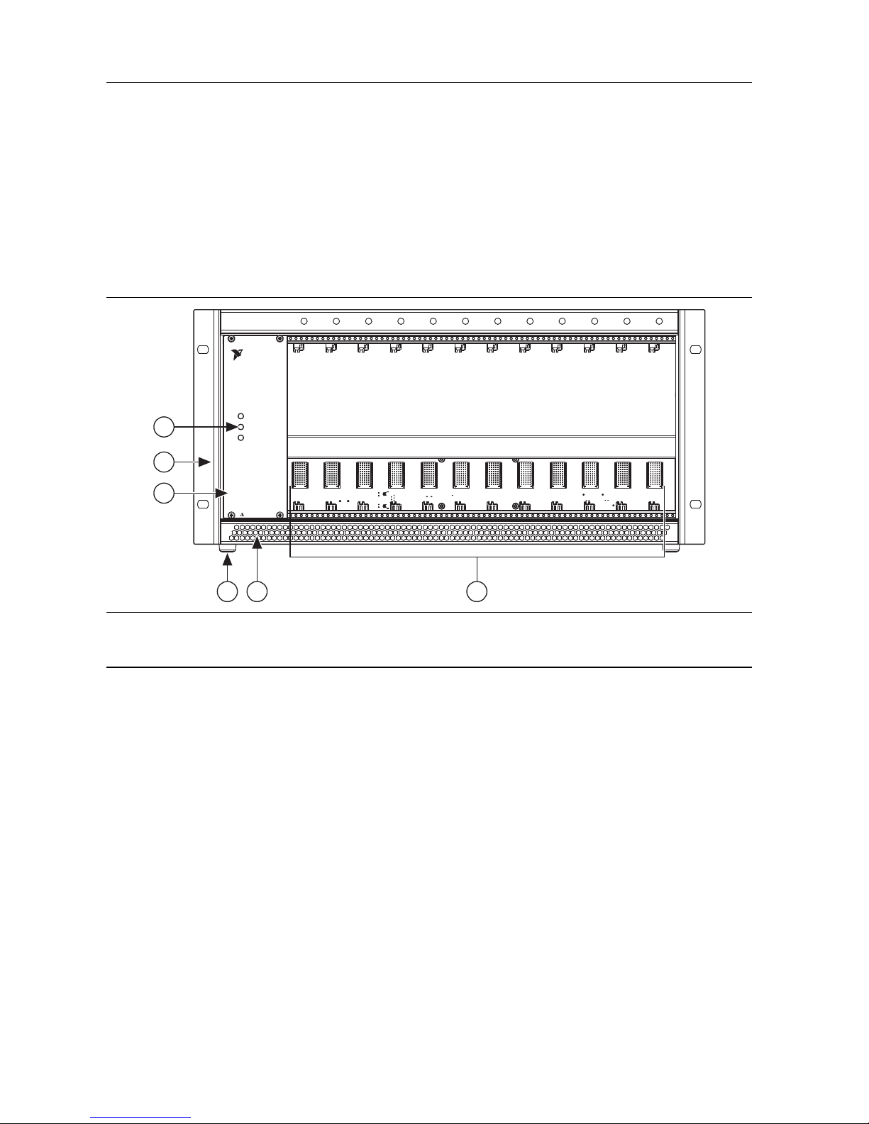
Figure 1 shows the front features of the SLSC-12001 chassis.
Figure 1. SLSC-12001 Chassis Front View
1 POWER, STATUS, and ACTIVITY LEDs
2 Mounting Bracket (2)
3 Chassis Model Name
4 Chassis Feet (4)
5 Front Air Intake
6 SLSC Peripheral Slots (12)
4 | ni.com | SLSC-12001 Chassis Getting Started Guide and Specifications
Page 5
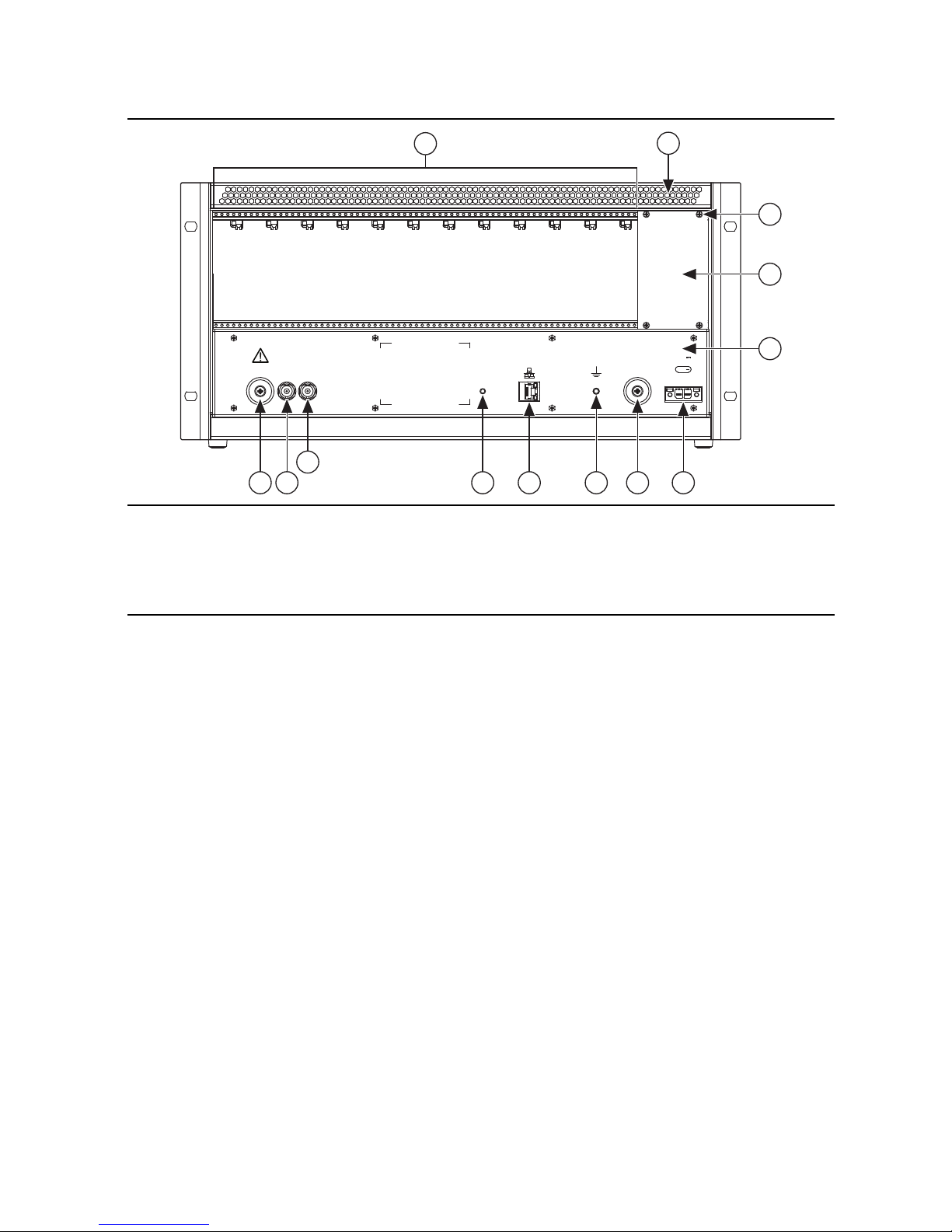
Figure 2 shows the rear features of the SLSC-12001 chassis.
DO NOT TOUCH CONTACTS OR
REMOVE I/O BOARDS OR CABLES
WHILE SYSTEM IS ENERGIZED.
TRIG 0 TRIG 1
RESET
ACT
SPD
720W MAX
+24V
+
4
1
2
5 56
7
8 109 11
12
3
Figure 2. SLSC-12001 Chassis Rear View
1 SLSC Peripheral Rear I/O Area
2 Rear Air Exhaust
3 Upper Rear Panel Screws (4)
4 Upper Rear Panel
5 Bumpers (2)
6 Trigger 0
7 Trigger 1
8Button
9 Ethernet Port
10 Chassis Ground Screw
11 DC Voltage Input
12 Backplane Panel
SLSC-12001 Chassis Getting Started Guide and Specifications | © National Instruments | 5
Page 6
SLSC-12001 Chassis Block Diagram
Battery
Host
System
Host DAQ
or other
trigger
source
+24 V
Supply
+24 V
Power
Input
Triggers
GigE
24 V
0-5 V
Ethernet
Power
Distribution
and
Protection
SLSC
Chassis
Manager
Real
Time
Clock
SLSC Module
SLSC Module
SLSC Module
Fans
I/O
I/O
I/O
SLSC-12001 Chassis
SLSC Interface
+24 V and +3.3 V
Digital Signals
Powe r
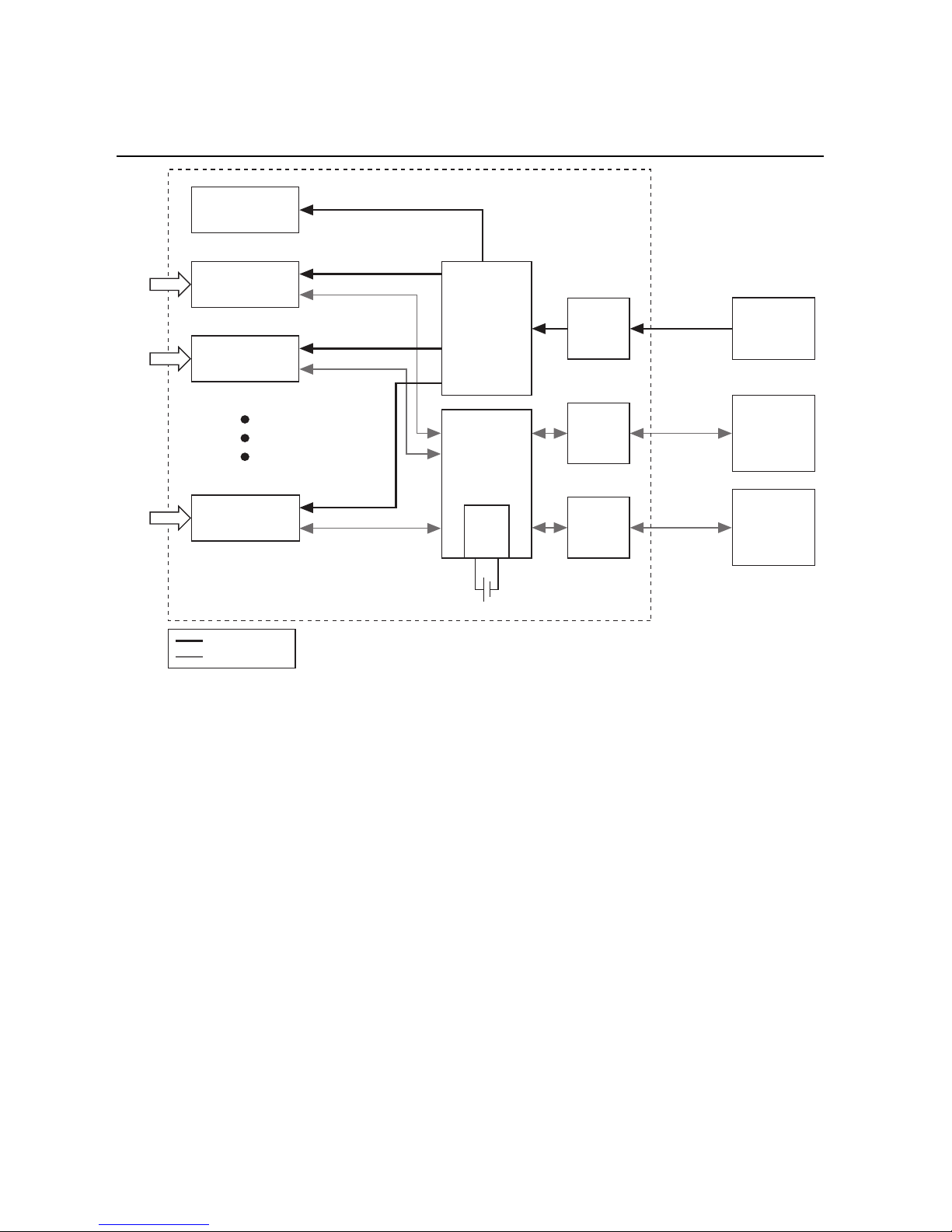
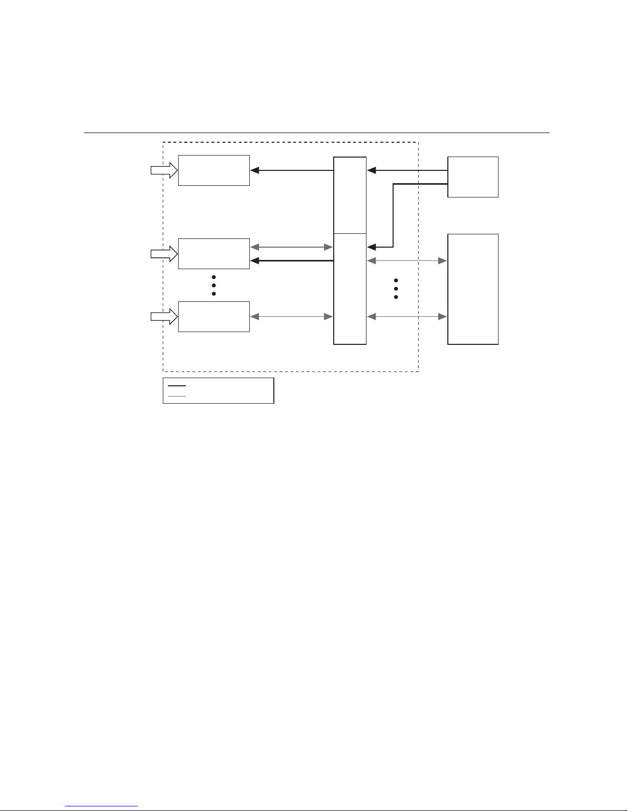
Figure 3 shows the SLSC-12001 chassis block diagram.
Figure 3. SLSC-12001 Chassis Block Diagram
The chassis power comes from an external +24 V supply and is distributed to each SLSC module
through an internal power bus. The +24 V bus has input overvoltage, reverse voltage, and short
circuit protection at each SLSC module output. The chassis does not have a power switch,
therefore power is energized as soon as the external power supply is connected to the chassis
and powered.
The SLSC-12001 chassis communicates with each module through the SLSC interface and
manages the Ethernet connectivity with a host computer.
The SLSC-12001 chassis also has built-in diagnosis functions, such as battery and fan
monitoring, that is accessible through the NI-SLSC driver. The chassis will shut down the
24 V rail supplied to the module unless all 5 fans are powered.
6 | ni.com | SLSC-12001 Chassis Getting Started Guide and Specifications
Page 7
SLSC-12001 Chassis Rear Transition Interface
DAQ
System
Power
Rear Transition
Interface
Rear Transition
Interface
SLSC Module
SLSC Module
SLSC Module
I/O
I/O
I/O
SLSC-12001 Chassis
Conditioned
Signals
Digital/Analog Signals
Powe r
An optional secondary backplane, RTI, may be used with the SLSC-12001 chassis to route
conditioned I/O signals directly to the DAQ system. The RTI can be used to distribute additional
power to one or more modules as shown in Figure 4.
Figure 4. Rear Transition Interface
RTIs must be implemented as follows:
1. All slots must have the SLSC Peripheral Rear I/O Area covered by either an RTI or rear
2. RTI implementation is flexible and can be used as follows:
filler panel to meet EMC and airflow requirements.
• An RTI can be a single slot width therefore resulting in 12 RTIs.
• An RTI can be a single PCB 12 slots wide taking into account all slots.
• An RTI can cover any number of slots from 1 to 12.
SLSC-12001 Chassis Getting Started Guide and Specifications | © National Instruments | 7
Page 8
Installing the Chassis
2
1
101.60 mm
(4.00 in.)
101.60 mm
(4.00 in.)
The SLSC-12001 chassis is designed to operate in an instrument rack with cooling clearances
to allow for proper airflow circulation.
Caution The SLSC-12001 chassis must be installed in a rack or similar enclosure
that ensures the rear of the chassis is not accessible (per IEC 61010-1) during normal
use. Access to the RTIs must require a tool. The front of the chassis may remain
accessible. Additionally, the rack or enclosure must meet the enclosure requirements
of IEC 61010-1 for containing the potential spread of fire from the RTIs.
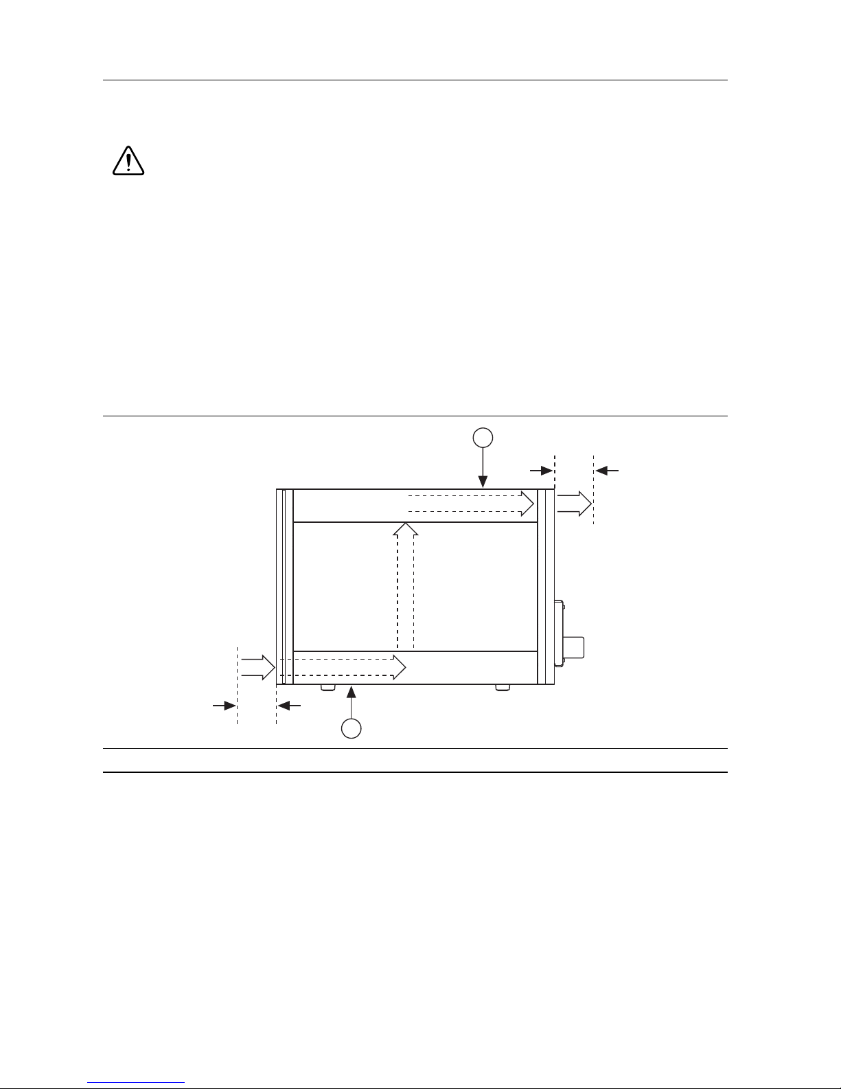
The SLSC-12001 chassis cooling inlet air vents are located on the front lower side of the chassis
and the outlet air vents are on the back upper side of the chassis. Position the air inlet to pull
air from outside the instrument rack. For best performance the air vents must allow easy air
circulation without wiring or panels blocking the vents. Refer to Figure 5 for airflow and
clearance information.
Figure 5. SLSC-12001 Chassis Airflow
1 Airflow Out 2 Airflow In
In order to operate the chassis at the maximum allowable ambient temperature and maximum
power as specified in the Environmental section, you must mount the chassis horizontally in the
rack and allow for airflow at the intake and exhaust as shown in Figure 5. Filler panels, which
are available at
ni.com, must be inserted in any empty front module slots and in any empty rear
RTI slots.
8 | ni.com | SLSC-12001 Chassis Getting Started Guide and Specifications
Page 9

Installing Rear Transition Interfaces
Caution Do not touch or remove the I/O boards or cables while the system is
energized. I/O boards may have exposed hazardous live voltages. Access must be
prevented in normal operation
Note Refer to RTI manufacturer documentation for product-specific installation
instructions.
NI recommends installing all RTIs prior to the initial module installation. Complete the
following steps to install RTIs:
1. Power off the main DC power source or disconnect it from the chassis before installing
any RTI.
2. Ensure that the chassis is powered off. The POWER LED should be off. If it is not off,
do not proceed until the POWER LED is off.
3. Loosen the screws of the upper rear panel. Refer to Figure 2 for the upper rear panel screws
locations.
4. Position the RTI at the desired slot and insert the securing screws, but do not fully tighten
them.
5. Insert a corresponding module in the same slot providing additional resistance at the rear
of the RTI for the module to fully mate to the RTI.
6. Repeat steps 4 and 5 for all required RTIs.
7. Tighten the screws for all RTIs and the upper rear panel. This ensures proper alignment for
future connections between modules and these RTIs.
Installing SLSC Modules
Caution The SLSC-12001 chassis and the SLSC modules do not support hot
plug-in. The entire chassis must be powered down when a module is installed.
Complete the following steps to install an SLSC module in the chassis while referring to
Figure 6:
Caution Power off the main DC power source or disconnect it from the chassis
before installing the module. To completely remove power, you must disconnect
all power cables.
Note Refer to module and RTI documentation to ensure electrical compatibility for
rear I/O connections.
1. Ensure that the chassis is powered off. The POWER LED should be off. If it is not off,
do not proceed until the POWER LED is off.
SLSC-12001 Chassis Getting Started Guide and Specifications | © National Instruments | 9
Page 10

2. Ensure that any alternate power source(s) connected the RTI(s) or modules are powered off.
S
LS
C-120
0
1
S
W
I
T
C
H
/
L
O
AD
/
S
I
G
NA
L
C
ON
D.
D
O
N
O
T
I
N
S
E
R
T
O
R
R
E
MOV
E
MO
D
U
L
E
S
WH
I
L
E
P
O
WE
R
E
D
P
OW
E
R
ACT
I
V
I
T
Y
S
T
A
T
US
S
LS
C-120
0
1
S
W
I
T
C
H
/
L
O
AD
/
S
I
G
NA
L
C
ON
D.
D
O
N
O
T
I
N
S
E
R
T
O
R
R
E
MOV
E
MO
D
U
L
E
S
WH
I
L
E
P
O
WE
R
E
D
P
OW
E
R
ACT
I
V
I
T
Y
S
T
A
T
US
2
1
3. Inspect the slot pins on the chassis backplane for any bending or damage prior to installing
a module.
4. Install a module into a chassis slot by first placing the module PCB into the front of the PCB
guides at the top and bottom.
5. Slide the module into the chassis until you begin to feel resistance then push up the
injector/ejector handle to fully seat the module into the chassis frame.
6. Secure the module front panel to the chassis using the module front-panel mounting screws.
Figure 6. SLSC-12001 Module Installation
1 Module 2 Injector/Ejector Handle
Removing SLSC Modules
Caution The SLSC-12001 chassis and the SLSC modules do not support hot
plug-in. The entire chassis must be powered down when a module is removed.
Complete the following steps to remove an SLSC module from the chassis:
1. Power off the main DC power source or disconnect it from the chassis before removing the
module.
2. Ensure that the chassis is powered off. The POWER LED should be off. If it is not off,
do not proceed until the POWER LED is off.
3. Ensure that any alternate power source(s) connected the RTI(s) are powered off.
10 | ni.com | SLSC-12001 Chassis Getting Started Guide and Specifications
Page 11

4. Unsecure the module front panel from the chassis by loosening the module front-panel
mounting screws.
5. Push down on the injector/ejector handle to pull the module away from the backplane
connector(s).
6. Slide the module to the front of the chassis, making sure the module remains in the guide
rails as you slide it out of the chassis.
Connecting the Chassis
Safety Guidelines
Caution Before undertaking any troubleshooting, maintenance, or exploratory
procedure; carefully read the following cautionary notices.
• Chassis Grounding—The SLSC chassis grounding screw may be connected to facility
ground. Refer to the Grounding the Chassis section for instructions on connecting a
grounding conductor.
– Live Circuits—Operating personnel and service personnel must not remove
protective covers when operating or servicing the chassis. Adjustments and service
to internal components must be undertaken by qualified service technicians. During
service of this product, disconnect the external power supply from the SLSC chassis.
– Explosive Atmosphere—Do not operate the chassis in conditions where flammable
gases are present. Under such conditions, this equipment is unsafe and may ignite the
gases or gas fumes.
– Part Replacement—Only service this equipment with parts that are exact
replacements, both electrically and mechanically. Contact NI for replacement part
information. Installation of parts with those that are not direct replacements can cause
harm to personnel operating the chassis. Furthermore, damage or fire may occur if
replacement parts are unsuitable.
– Modification—Do not modify any part of the chassis from its original condition.
Unsuitable modifications can result in safety hazards.
Grounding the Chassis
Connect the grounding electrode system of the facility to the chassis using the chassis grounding
screw located on the back of the SLSC-12001 chassis. Refer to Figure 2 for the location of the
chassis ground screw. Use an AWG 8 wire with a lug as appropriate for your application.
Wiring Power to the Chassis
The SLSC-12001 chassis requires a +24 V, DC supply as power for the chassis and installed
modules. Refer to the Chassis Power section for the minimum specifications of the external
power supply. For best results ensure that the external power supply is mounted as required
by the manufacturer and has enough air circulation for proper cooling.
SLSC-12001 Chassis Getting Started Guide and Specifications | © National Instruments | 11
Page 12

The SLSC-12001 chassis can draw a significant current from the +24 V power input to support
module requirements. Refer to the Physical Characteristics section for wire gauge sizes
permitted by the SLSC-12001 chassis connector when wiring the power. Minimize the cable
length between the power supply and SLSC-12001 chassis. Avoid unnecessary intermediate
connections on the power lines. If possible, direct wiring between the power supply and chassis
is preferred.
Complete the following steps to connect the external power supply:
1. Ensure the +24 V external power supply is powered off.
2. Wire the power supply to the SLSC-12001 chassis power input connector, which is shipped
with the SLSC-12001 chassis. Refer to the Physical Characteristics section for wire gauge
information. Refer to Table 1 for signal connection information.
Table 1. Power Input Cable Connector
Connector Pin Description
- Negative power input
–
+
+ Positive power input
3. Install the power connector on the rear of the SLSC-12001 chassis and secure it with the
locking tabs.
Note If a source with remote sensing is used, connect the sensing wires as close
as possible to the chassis power input connector.
Powering on the Chassis
The SLSC-12001 chassis does not have an on/off switch since an external power supply
provides power to the SLSC-12001 chassis. Connecting an already powered on 24 V supply
to the SLSC-12001 is allowed, but higher transient currents may be involved.
When you apply power to the SLSC-12001, the chassis fans start and the POWER LED should
turn green immediately. When the POWER LED and the STATUS LED are both green, the
chassis is ready for host communication. Refer to the Understanding LED Indicators section
to identify other LED indications.
Note Ensure that SLSC modules are installed in the chassis prior to power-up.
12 | ni.com | SLSC-12001 Chassis Getting Started Guide and Specifications
Page 13

Note If an SLSC module requires auxiliary power supplies, refer to the module
datasheet to determine the power-up sequence.
Tip After the SLSC-12001 is powered on, check the voltage at the chassis power
connector to ensure that the power line does not drop below the minimum operational
voltage range specified in the Chassis Power section.
Connecting the Chassis to a Host
Use a shielded Category 5 Ethernet cable to connect the SLSC-12001 using one of the following
methods:
Note By default, the SLSC-12001 uses DHCP to acquire an IP address. If the
network to which it is connected does not have a DHCP server, the SLSC-12001
assigns itself a link-local IP address. To use a static IP address, you must use DHCP
or link-local to access the web-based configuration interface of the SLSC-12001 and
then reconfigure it to use a static IP address.
• Connect the SLSC-12001 to the network, typically through a router or switch shared with
the host using a standard Ethernet cable.
• Connect the SLSC-12001 to the Ethernet port on the host system using an Ethernet
crossover cable.
Connecting to a Measurement System
The SLSC-12001 direct signal connection to a measurement system is optimized to be
completed through RTI(s) as required by individual SLSC modules. Use signal cables as
required by individual SLSC modules and measurements system to route the signals.
Maintenance
Power off the chassis and any alternate power supplies connected to the modules or RTIs when
performing maintenance on the chassis. After maintenance is complete, ensure that the chassis
is completely dry and free from contaminants before returning it to service.
Caution Many components within the chassis are susceptible to static discharge
damage. Service the chassis only in a static-free environment. Observe standard
handling precautions for static-sensitive devices while servicing the chassis. Always
wear a grounded wrist strap or equivalent while servicing the chassis.
Cleaning the Chassis
Clean dust from the chassis exterior and interior as needed, based on the operating environment.
Periodic cleaning increases reliability.
Use a dry, low-velocity stream of air to clean the interior of the chassis. Use a soft-bristle brush
for cleaning around components.
SLSC-12001 Chassis Getting Started Guide and Specifications | © National Instruments | 13
Page 14

Clean the exterior surfaces of the chassis with a dry lint-free cloth or a soft-bristle brush. If any
dirt remains, wipe with a cloth moistened in a mild soap solution. Remove any soap residue by
wiping with a cloth moistened with clear water. Do not use abrasive compounds on any part of
the chassis.
Cleaning and Replacing the Chassis Intake Filter
Caution Operating the SLSC-12001 without the chassis intake filter installed
degrades the cooling performance of the chassis.
Cleaning the Filter
A dirty intake filter dramatically affects the cooling performance of an SLSC-12001 chassis.
Clean the intake filter whenever it becomes visibly dirty.
1. For minor dust buildup, you can vacuum the intake filter without removing it from the
chassis.
2. For significant dust buildup, NI recommends removing and cleaning the intake filter,
or replacing the intake filter.
• Clean the intake filter by:
1. Washing it in a mild soap solution.
2. Rinsing it with water.
3. Vacuuming or blowing air through it.
4. Allowing it to dry before reinstalling it in the chassis.
• You can replace the intake filter with a new one, which is available from
ni.com.
Removing the Filter
1. Remove the four screws from the front panel that contains the chassis LEDs and set them
aside.
2. Remove the front panel that contains the chassis LEDs and set it aside.
3. Reach into the bottom front of the chassis and pull out the intake filter.
Inserting the Filter
1. Remove modules as needed to place the intake filter in its original location flush against the
chassis intake across the entire front length of the chassis.
2. Ensure that the intake filter is oriented as shown in Figure 7.
3. Reinsert the front panel that contains the LEDs.
4. Install the four front panel screws.
14 | ni.com | SLSC-12001 Chassis Getting Started Guide and Specifications
Page 15

Figure 7. Intake Filter Orientation
S
LS
C-120
0
1
S
W
I
T
CH/
L
O
AD/
SI
G
N
A
L
CO
N
D
.
P
OW
E
R
ACT
I
V
I
T
Y
S
T
A
T
US
S
LS
C-120
0
1
S
W
I
T
CH/
L
O
AD/
SI
G
N
A
L
CO
N
D
.
D
O
N
O
T
I
N
S
E
RT
O
R
R
E
MOV
E
MO
D
U
L
E
S
WH
I
L
E
P
O
W
E
R
E
D
P
OW
E
R
ACT
I
V
I
T
Y
S
T
A
T
US
1
2 3
4035302520
60,000
20,000
10,000
0
Chassis Intake Temperature (°C)
Operating Duration (Hours)
30,000
40,000
50,000
70,000
80,000
50 W per Module Average
40 W per Module Average
30 W per Module Average
1Filter
3 Chassis Side Sectioned View
2 Filter Inserted in Correct Orientation
Fan Maintenance
Figure 8 shows estimated fan life based on empirical and manufacturer reliability information.
Actual fan operating life may vary based on individual module airflow and heat dissipation
characteristics. The information provided in Figure 8 allows you to maximize the performance
and operation of the SLSC-12001 chassis by allowing you to manage maintenance schedules.
Figure 8. Projected Fan Lifetime
SLSC-12001 Chassis Getting Started Guide and Specifications | © National Instruments | 15
Page 16

Fan Replacement
National Instruments provides a replacement kit containing five fans and two plastic cable ties.
The replacement kit is available at ni.com.
Fan Removal
1. Insert a small flathead screwdriver into the small notches shown in Figure 9 to remove the
side panels.
Figure 9. Removing Chassis Panels
2
3
1 1
N
A
T
IN
ION
S
T
AL
R
UM
EN
T
S
4
S
L
S
S
W
C-12001
I
T
C
H
/
L
O
A
D
/
S
I
G
N
A
L
C
O
N
D
.
N
ATIO
IN
ST
N
AL
R
UM
E
N
T
S
S
L
S
S
W
C-12001
I
T
C
H
/
L
O
A
D
/
S
I
G
N
A
L
C
O
N
D
.
4
3
1 Top Panel
2 Top Panel Retention Screw (2)
3 Side Panel (2)
4 Notches for Screwdriver Insertion
2. Remove the two top panel retention screws using a Phillips screwdriver.
Note Use care when reinstalling the top panel retention screws. These are
thread-forming screws and may cause cross-threading damage if inserted incorrectly.
3. Remove the top panel by holding its side edges and lifting it off the chassis.
4. Locate the fan terminal block, by referring to Figure 10.
5. Disconnect the wires associated with the fan(s) that you want to replace. Figure 12
illustrates the fan wire locations.
2
3
a. Insert a small flathead screwdriver into a spring clamp activation slot to open the
corresponding connector terminal as shown in Figure 11.
b. Pull the wire out of the connector terminal and remove the screwdriver.
c. Repeat step a and b for each fan you replace.
6. Cut the plastic cable ties shown in Figure 10.
7. Lift the fan(s) vertically from the standoffs.
16 | ni.com | SLSC-12001 Chassis Getting Started Guide and Specifications
Page 17

Figure 10. Chassis Fan Components
2
1
3
4
9
1Fan 1
2Fan 2
3 Standoff (15)
4Fan 3
5Fan 5
NATIONAL
8
INSTRUMENTS
S
LSC
SW
IT
C
H
/
LO
-1
A
2
D
/SIG
0
N
0
A
L
1
C
O
N
D
.
7
6 Fan Terminal Block
7 Plastic Cable Ties and Cable Tie Anchors
8 Fan 4
9 Fan Power Cable
Figure 11. Fan Terminal Block Wire Removal and Insertion
5
6
3+
F4+
F
F2+
F1+
F4–
F3–
F2–
F1–
1 2 3 4
1 Step 1 Insert the Screwdriver
2 Step 2 Remove the Fan Terminal Block Wire
SLSC-12001 Chassis Getting Started Guide and Specifications | © National Instruments | 17
4+
F
F3+
F2+
F1+
F4–
F3–
F2–
F1–
F4+
3+
2+
F
F
F1+
F4–
F3–
F2–
F1–
4+
F
F3+
F2+
F1+
F4–
F3–
F2–
F1–
3 Step 3 Replace the Fan Terminal Block Wire
4 Step 4 Remove the Screwdriver
Page 18

Figure 12. Fan Terminal Block Wiring
Fan 4 Red (+)
Fan 3 Red (+)
Fan 2 Red (+)
Fan 1 Red (+)
Fan 4 Black (–)
Fan 3 Black (–)
Fan 2 Black (–)
Fan 1 Black (–)
F4+
F3+
F2+
F1+
F4–
F3–
F2–
F1–
F5+
Fan 5 Red (+)
J+
J+
V+
Fan Pwr (+)
Fan 5 Black (–)
F5–
J–
J–
V–
Fan Pwr (–)
Fan Installation
1. Slide the fan(s) down onto the standoffs.
2. Connect the fan wires to the terminal block as shown in Figure 12 using the process shown
in Figure 11.
a. Insert the screwdriver into the spring clamp activation slot to open the corresponding
connector terminal.
b. Press the new fan wire into the open connector terminal.
c. Remove the screwdriver from the activation slot to clamp the wire into place.
d. Repeat step a through c for each fan you install.
3. Route the wires between the fans, not over them. For fan 3 in Figure 10, route the wire
beneath the fan tray and back through the two small grommets shown in Figure 13. Pull
the wire taut to prevent it from dangling loosely beneath the tray.
4. Coil up the wires and cable as needed to prevent the wires from being pinched when the
panel is reattached. Use the chassis sheet metal cable tie anchors shown in Figure 10, and
the plastic cable ties from the fan kit to hold the wires and cable tightly in place. Figure 14
illustrates the anchor and cable tie detail.
5. Replace the top panel with the vent holes toward the back.
6. Reinsert the two top panel retention screws using a Phillips screwdriver and tighten the
screws to a torque of 1.92 N · m (17 lb · in.).
7. Replace the side panels.
18 | ni.com | SLSC-12001 Chassis Getting Started Guide and Specifications
Page 19

1 Small Grommets
Figure 13. Fan 3 Wiring Detail
1
Figure 14. Tie Anchor Detail
2
1
3
1Wires
2 Plastic Cable Tie
3 Cable Tie Anchor
Battery Replacement
The SLSC-12001 contains a lithium cell battery that is required for storing the Real Time Clock
information when the chassis is powered off. There is only a slight drain on the battery when
power is applied to the SLSC-12001 power connector. The rate at which the battery drains when
power is disconnected depends on the ambient storage temperature. The battery is located on the
backplane. To replace the battery, complete the following steps while referring to Figure 15:
1. Power off the chassis and any power source(s) connected to module(s) and RTI(s).
2. Remove the chassis power, trigger, and Ethernet cables from the chassis.
3. Remove the washer and nut from around each BNC connector.
4. Remove the eight backplane panel fixing screws.
SLSC-12001 Chassis Getting Started Guide and Specifications | © National Instruments | 19
Page 20

5. Remove the backplane panel.
D
O
N
O
T
T
O
U
C
H
C
O
N
T
A
C
TS O
R
R
EMO
VE I/O
B
OA
R
D
S
O
R
C
A
B
LES
W
H
IL
E SYSTEM
IS EN
ER
G
IZED.
T
R
IG
0
TR
IG
1
5
6
4
3
2
1
6. Remove the battery.
Note Refer to the Battery Replacement and Disposal section for information about
proper disposal of the old battery.
7. Replace the battery with a new Tadiran TL-2450 or an equivalent battery.
8. Replace the backplane panel.
9. Secure the back panel with the eight fixing screws tightened to a torque of 0.56 N · m
(5 lb · in.).
10. Secure each BNC connector with a washer and nut.
11. Replace the chassis power connector.
Once the battery is replaced, the Real Time Clock will reset. Refer to NI-SLSC Help for
information about setting the clock.
Figure 15. SLSC-12001 Chassis Battery Replacement
1 Backplane Panel
2 Backplane Panel Affixing Screws (8)
3 BNC Connector Washer (2)
20 | ni.com | SLSC-12001 Chassis Getting Started Guide and Specifications
4 BNC Connector Nut (2)
5Battery
6 Chassis Power Connector
Page 21

Troubleshooting
Understanding LED Indicators
The SLSC-12001 has three LEDs on the front panel. The significance of the LEDs is described
in Table 2.
Table 2. Troubleshooting Using LED Indicators
LED Type LED Indicator Status
POWER Off No power or short circuit on +3.3 V rail causing failure to
power on.
Green Power is on.
ACTIVITY Blinking green Ethernet communication in progress.
Off No Ethernet communication.
STATUS Red Less than 3 seconds: chassis is starting to boot.
Reset button is pressed.
More than 3 seconds after boot start: chassis failed to
boot. This could be due to corrupt firmware, incorrect
power input, fan failure, or other hardware issues.
Amber Chassis is booting.
Green Normal operation.
Network Communication Troubleshooting
Multiple problems may result in network communication issues during setup.
Things to try:
• Ensure the chassis is connected to a working 24 VDC power source.
• If the STATUS LED is off, there may be a short circuit. Refer to the Module Short Circuit
Behavior section for more information.
• If the STATUS LED is green, but the ACTIVITY LED is off, try the following:
– Verify the Ethernet cable is connected properly.
– If communication is routed through a switch, verify that the switch is powered on and
functioning.
– Verify that your network has a DHCP server or that the chassis is connected to the host
system using a crossover cable.
– Verify that the host computer firewall is disabled.
– Verify that the host computer is not configured to use a proxy server.
SLSC-12001 Chassis Getting Started Guide and Specifications | © National Instruments | 21
Page 22

Resetting the Chassis and Modules
The SLSC-12001 chassis has a button, located on the rear of the chassis.
Pressing the reset button results in the following chassis responses:
• Reset—When pressed for less than five seconds, the chassis reboots with the current
configuration.
• Factory Reset—When pressed for five seconds or longer, then released, the chassis reboots
into factory default mode, which returns the chassis user configuration to the factory-set
defaults listed in Table 3. If the chassis was set to a static IP address, it takes two factory
resets to revert to DHCP or Link Local IP address.
Table 3. SLSC-12001 Factory Default Mode Settings
Attribute Value
Host Name/Chassis Name SLSC-12001-<8-digit serial number>
Module Name SLSC-12001-<8-digit serial number>-Mod<slot number>
IP DHCP or Link Local
Comment Empty
NI Auth User name = admin Password = no password required
User name = anonymous Password = no password required
Note: If the serial number is less than 8-digits, zeros will be added to the front of the serial number to
make it 8 digits long.
Fan Faults
The NI-SLSC software driver provides the ability to monitor the SLSC-12001 Fan Voltage
Sensor to determine whether a fan fault is detected. This feature allows you to determine when
a fan should be replaced. If fan faults are not resolved immediately, system performance is
impacted. Refer to the NI-SLSC Driver Help for more details on monitoring the fans. If the
SLSC-12001 detects that all fans have failed, the modules are sent a reset command and the
+24 V rail to each slot is turned off to prevent system damage.
Module Short Circuit Behavior
Each SLSC module is powered from the SLSC-12001 through +3.3 V and +24 V rails. If a
defective module is present, the SLSC-12001 may fail to start. If one SLSC module has a short
circuit condition on the +3.3 V rail, the SLSC-12001 chassis will not start, there will be no
Ethernet communication with the chassis, and all front panel LEDs will be off.
If one SLSC module has a short circuit condition on the +24 V rail, the +24 V rail is turned off
for all modules once the chassis starts and the POWER LED will be amber. In both cases, power
off the chassis and remove the defective module before attempting a restart.
22 | ni.com | SLSC-12001 Chassis Getting Started Guide and Specifications
Page 23

Specifications
The following specifications apply to an SLSC-12001 mounted in a rack with recommended
cooling clearances found in the Installing the Chassis section and using a power supply that
meets the specifications provided in this Specifications section. The specifications are valid
for the entire temperature range of the chassis unless otherwise specified.
Chassis Power
Nominal input voltage ...................................... 24 V
Maximum input voltage.................................... 27.6 V
Minimum input voltage .................................... 21 V
Maximum input voltage ripple
20 Hz to 20 MHz .............................................. 200 mV
Chassis power consumption (no modules) ....... 45 W
Maximum input current .................................... 35 A
Maximum power consumption with
modules............................................................. 720 W
Maximum power cable length .......................... 3 m
Note The external power supply must meet the DC input specifications at the
chassis input with a minimum power output of 720 W and must provide suitable
overvoltage and overcurrent protection as well as a suitable easily reached disconnect
switch or circuit breaker.
Note Depending on populated modules, the startup current could be significantly
higher than the steady DC current. The external power supply should sustain the
initial startup current without entering the overcurrent protection.
SLSC-12001 Chassis Getting Started Guide and Specifications | © National Instruments | 23
Page 24

Table 4. DC Output per Slot
Rail Minimum Volts Maximum Volts Maximum Current Comments
24 V 20.4 26.4 2 A Across two pins
3.3 V 3.135 3.465 400 mA —
Note Each slot has short circuit protection.
SLSC-12001 power dissipation
Maximum chassis power dissipation ........650 W
Maximum continuous
power dissipation per slot .........................50 W
Battery
Battery type....................................................... Tadiran TL-2450
Typical battery life with power applied
to power connector............................................ 8 years
Network
Network interface .............................................10BASE-T, 100BASE-T, 1000BASE-T
Ethernet compatibility....................................... IEEE 802.3
Communication rates ........................................10 Mbps, 100 Mbps, 1,000 Mbps
auto-negotiated
Maximum cabling distance...............................100 m/segment
24 | ni.com | SLSC-12001 Chassis Getting Started Guide and Specifications
Page 25

Physical Characteristics
Figure 16. SLSC-12001 Dimensions
36.5 mm
(1.44 in.)
315.56 mm
(12.42 in.)
325.26 mm
(12.81 in.)
23.83 mm
(0.95 in.)
448.9 mm
(17.67 in.)
482.6 mm
(19.00 in.)
POWER
228.65 mm
(9.00 in.)
POWER
ACTIVITY
ACTIVITY
STATUS
STATUS
SLSC-12001
SWITCH/LOAD/SIGNAL COND.
DO NOT INSERT OR REMOVE
DO NOT INSERT OR REMOVE
MODULES WHILE POWERED
MODULES WHILE POWERED
7.2 mm
(0.28 in.)
Power connector screw-terminal
wire gauge......................................................... 8.36 mm2 (8 AWG)
Power connector screw-terminal
wire type ........................................................... Copper conductor wire
SLSC-12001 Chassis Getting Started Guide and Specifications | © National Instruments | 25
Page 26

Power connector screw-terminal
wire strip length ................................................10 mm (0.394 in.) of insulation stripped
from the end
Power connector screw-terminal
screw torque ...................................................... 0.5 N · m (4.4 lb · in.)
Weight (chassis only)........................................6.2 kg (13.6 lb)
Chassis Cooling
Module cooling system
Slot airflow direction ................................ Bottom of module to top of module
Module cooling intake .............................. Bottom front of chassis
Module cooling exhaust............................Top rear of chassis
Environmental
Operating temperature at chassis air intake ......0 °C to 40 °C
1
(Tested in accordance with IEC 60068-2-1 and
IEC 60068-2-2.)
Storage temperature range ................................ -40 °C to 85 °C
(Tested in accordance with IEC 60068-2-1 and
IEC 60068-2-2.)
Relative humidity range, operating...................10% to 90%, noncondensing
(Tested in accordance with IEC 60068-2-56.)
Relative humidity range, storage ......................5% to 95%, noncondensing
(Tested in accordance with IEC 60068-2-56.)
Maximum altitude.............................................2,000 m (800 mbar) (at 25 °C ambient)
Pollution Degree ...............................................2
Indoor use only.
1
The chassis internal ambient temperature may reach 85 °C with all slots at the maximum allowed power
dissipation.
26 | ni.com | SLSC-12001 Chassis Getting Started Guide and Specifications
Page 27

Shock and Vibration
Operational shock ............................................. 30 g peak, half-sine, 11 ms pulse
(Tested in accordance with IEC 60068-2-27.
Meets MIL-PRF-28800F Class 2 limits.)
Operating vibration, random............................. 5 Hz to 500 Hz, 0.3 g
(Tested in accordance with IEC 60068-2-64.)
Non-operating vibration, random ..................... 5 Hz to 500 Hz, 2.4 g
(Tested in accordance with IEC 60068-2-64.
Non-operating test profile exceeds the
requirements of MIL-PRF-28800F, Class 3.)
rms
rms
Safety
Measurement Category1................................... I
Caution Do not connect the SLSC-12001 to signals or use for measurements
within Measurement Categories II, III or IV.
Caution The protection provided by the SLSC-12001 can be impaired if it is used
in a manner not described in this document.
Safety Standards
This product meets the requirements of the following standards of safety for electrical equipment
for measurement, control, and laboratory use:
• IEC 61010-1, EN 61010-1
• UL 61010-1, CSA C22.2 No. 61010-1
Note For UL and other safety certifications, refer to the product label or the Online
Product Certification section.
Electromagnetic Compatibility
This product meets the requirements of the following EMC standards for electrical equipment
for measurement, control, and laboratory use:
• EN 61326-1 (IEC 61326-1): Class A emissions; Basic immunity
• EN 55011 (CISPR 11): Group 1, Class A emissions
• EN 55022 (CISPR 22): Class A emissions
• EN 55024 (CISPR 24): Immunity
• AS/NZS CISPR 11: Group 1, Class A emissions
1
Measurement Categories CAT I and CAT O are equivalent. These test and measurement circuits are not
intended for direct connection to the MAINS building installations of Measurement Categories CAT II,
CAT III, or CAT IV.
SLSC-12001 Chassis Getting Started Guide and Specifications | © National Instruments | 27
Page 28

• AS/NZS CISPR 22: Class A emissions
• FCC 47 CFR Part 15B: Class A emissions
• ICES-001: Class A emissions
Note In the United States (per FCC 47 CFR), Class A equipment is intended for use
in commercial, light-industrial, and heavy-industrial locations. In Europe, Canada,
Australia and New Zealand (per CISPR 11) Class A equipment is intended for use
only in heavy-industrial locations.
Note Group 1 equipment (per CISPR 11) is any industrial, scientific, or medical
equipment that does not intentionally generate radio frequency energy for the
treatment of material or inspection/analysis purposes.
Note For the standards applied to assess the EMC of this product, refer to the
Online Product Certification section.
CE Compliance
This product meets the essential requirements of applicable European Directives as follows:
• 2014/35/EU; Low-Voltage Directive (safety)
• 2014/30/EU; Electromagnetic Compatibility Directive (EMC)
• 2011/65/EU; RoHS Directive
Online Product Certification
Refer to the product Declaration of Conformity (DoC) for additional regulatory compliance
information. To obtain product certifications and the DoC for this product, visit
certification
in the Certification column.
, search by model number or product line, and click the appropriate link
ni.com/
Environmental Management
NI is committed to designing and manufacturing products in an environmentally responsible
manner. NI recognizes that eliminating certain hazardous substances from our products is
beneficial to the environment and to NI customers.
For additional environmental information, refer to the Minimize our Environmental Impact
web page at
directives with which NI complies, as well as other environmental information not included in
this document.
ni.com/environment. This page contains the environmental regulations and
28 | ni.com | SLSC-12001 Chassis Getting Started Guide and Specifications
Page 29

Waste Electrical and Electronic Equipment (WEEE)
⬉ᄤֵᙃѻક∵ᶧࠊㅵ⧚ࡲ⊩ ˄Ё
RoHS
˅
Ёᅶ᠋
National Instruments
ヺড়Ё⬉ᄤֵᙃѻકЁ䰤ࠊՓ⫼ᶤѯ᳝ᆇ⠽䋼ᣛҸ
(RoHS)
DŽ݇Ѣ
National Instruments
Ё
RoHS
ড়㾘ᗻֵᙃˈ䇋ⱏᔩ
ni.com/
environment/rohs_china
DŽ
(For information about China RoHS compliance,
go to
ni.com/environment/rohs_china
.)
EU Customers At the end of the product life cycle, all products must be sent to
a WEEE recycling center. For more information about WEEE recycling centers,
National Instruments WEEE initiatives, and compliance with WEEE Directive
2002/96/EC on Waste and Electronic Equipment, visit
.
weee
ni.com/environment/
Battery Replacement and Disposal
Battery Directive This device contains a long-life coin cell battery. If you need
Cd/Hg/Pb
to replace it, use the Return Material Authorization (RMA) process or contact an
authorized National Instruments service representative. For more information
about compliance with the EU Battery Directive 2006/66/EC about Batteries
and Accumulators and Waste Batteries and Accumulators, visit
environment/batterydirective
.
ni.com/
Worldwide Support and Services
The NI website is your complete resource for technical support. At ni.com/support you have
access to everything from troubleshooting and application development self-help resources to
email and phone assistance from NI Application Engineers.
ni.com/services for NI Factory Installation Services, repairs, extended warranty, and
Visit
other services.
Visit ni.com/register to register your NI product. Product registration facilitates technical
support and ensures that you receive important information updates from NI.
NI corporate headquarters is located at 11500 North Mopac Expressway, Austin, Texas,
78759-3504. NI also has offices located around the world. For telephone support in the United
States, create your service request at
For telephone support outside the United States, visit the Worldwide Offices section of
ni.com/niglobal to access the branch office websites, which provide up-to-date contact
information, support phone numbers, email addresses, and current events.
ni.com/support or dial 1 866 ASK MYNI (275 6964).
SLSC-12001 Chassis Getting Started Guide and Specifications | © National Instruments | 29
Page 30

Refer to the NI Trademarks and Logo Guidelines at ni.com/trademarks for more information on National Instruments trademarks. Other
product and company names mentioned herein are trademarks or trade names of their respective companies. For patents covering National
Instruments products/technology, refer to the appropriate location: Help»Patents in your software, the patents.txt file on your media, or the
National Instruments Patents Notice at ni.com/patents. You can find information about end-user license agreements (EULAs) and third-party
legal notices in the readme file for your NI product. Refer to the Export Compliance Information at ni.com/legal/export-compliance
for the National Instruments global trade compliance policy and how to obtain relevant HTS codes, ECCNs, and other import/export data. NI MAKES
NO EXPRESS OR IMPLIED WARRANTIES AS TO THE ACCURACY OF THE INFORMATION CONTAINED HEREIN AND SHALL NOT BE LIABLE FOR
ANY ERRORS. U.S. Government Customers: The data contained in this manual was developed at private expense and is subject to the applicable
limited rights and restricted data rights as set forth in FAR 52.227-14, DFAR 252.227-7014, and DFAR 252.227-7015.
© 2016–2017 National Instruments. All rights reserved.
377023D-01 Oct17
 Loading...