

Page 1
USER GUIDE
Digital Flying Lead Cable
Accessory for Single-Ended NI Digital Waveform Generator/Analyzers
The NI SHC68-H1X38 cable is a single-ended cable that breaks out each
NI digital waveform generator/analyzer signal into two 0.1 inch header
receptacles, one receptacle each for the signal and ground. The
NI SHC68-H1X38 cable provides an easy way to connect NI single-ended
high-speed digital waveform generator/analyzer devices to various types of
devices and circuits for interfacing, testing, or analysis.
This cable offers connectivity similar to that found on a typical logic
analyzer, so you can use it in logic analyzer-type applications. Unlike a
typical logic analyzer, however, this cable also allows for simultaneous
pattern generation and acquisition so that it can be used in
stimulus/response applications as well.
This guide explains how to set up and use the NI SHC68-H1X38 cable with
single-ended NI digital waveform generator/analyzer modules.
Contents
What You Need to Get Started ............................................................... 2
Related Documentation........................................................................... 2
Parts Locator ........................................................................................... 3
Connecting Signals ................................................................................. 4
Using Your Accessory ............................................................................ 6
Specifications .......................................................................................... 7
Page 2

What You Need to Get Started
To set up and use the NI SHC68-H1X38 cable, you need the following
items:
❑ Compatible NI digital waveform generator/analyzer, installed in a PXI
chassis, compactPCI chassis, or PCI slot
❑ The documentation included with the digital waveform
generator/analyzer and driver software
Related Documentation
The NI digital waveform generator/analyzer ships with several documents
designed to familiarize you with different aspects of the module. The
documentation set includes the following pieces:
• NI Digital Waveform Generator/Analyzer Getting Started
Guide—Read this printed document to set up the digital waveform
generator/analyzer and configure it to complete your first acquisition
or generation.
• NI Digital Waveform Generator/Analyzer Help—This online
document provides more in-depth information about the hardware
capabilities of the module, theory of operation, programming flow, and
software reference.
• NI digital waveform generator/analyzer specifications—These printed
documents provide specifications for your device.
Digital Flying Lead Cable User Guide 2 ni.com
Page 3
Parts Locator
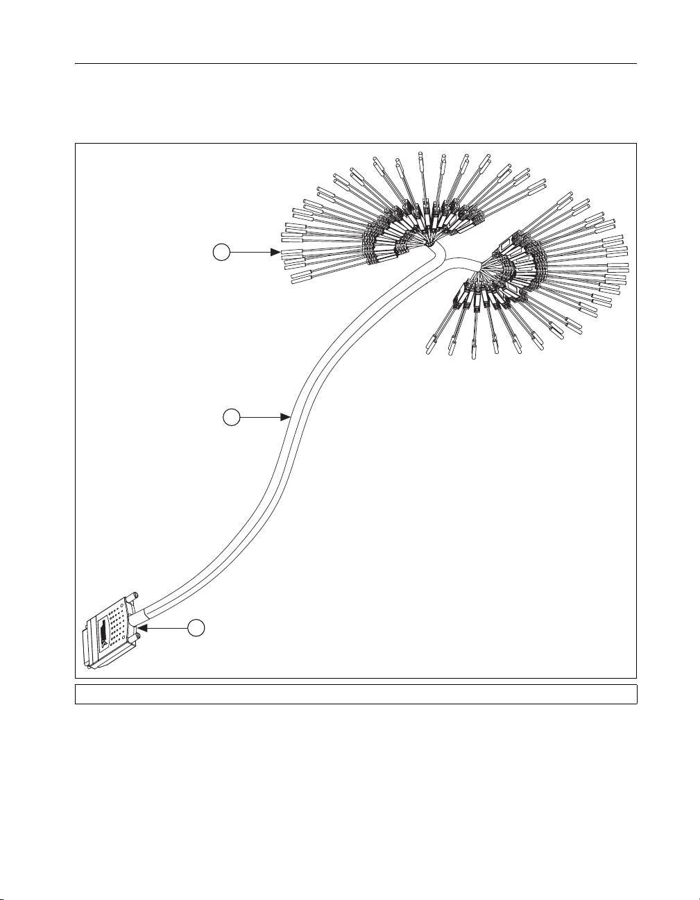
Refer to Figure 1 to locate connectors and components on the
NI SHC68-H1X38 cable. The lead pairs are shown in more detail in
Figure 2.
1
2
3
1 Lead Pairs 2 Removable Sleeving 3 68-Pin VHDCI Connector
Figure 1. NI SHC68-H1X38 Cable Parts Locator Diagram
© National Instruments Corporation 3 Digital Flying Lead Cable User Guide
Page 4

4
1
1 0.25 in. diameter 0.1 in. pitch
compatible receptacles
2 Strain-relief and label
Figure 2. Detailed Parts Locator Diagram for the Lead Pairs
Connecting Signals
Each DIO, PFI, and clock channel of the NI digital waveform
generator/analyzer connects to a corresponding pair of leads on the
NI SHC68-H1X38 cable.
The NI SHC68-H1X38 cable is separated into two bundles of 19 channels,
and each channel is split into a pair of leads for connecting the signal and
its associated ground. Table 1 describes the channels and shows how they
are grouped by bundle.
Table 1. NI Digital Waveform Generator/Analyzer Signal Descriptions
Channel Signal Description Bundle
DIO <0..31> Bidirectional digital data channels 0
through 31. Refer to the documentation
for your NI digital waveform
generator/analyzer for information about
the number of available DIO channels on
your device. DIO <20..31> may not
apply to your device.
2
3 Microcoaxial wire
4 Ground
DIO<0..15>: Bundle A
DIO<16..31>: Bundle B
3
STROBE / PFI 5 For devices that have a STROBE
Bundle A
channel, this signal is the external
Sample clock source for dynamic
acquisition. Otherwise, this is
programmable functional interface
(PFI) 5.
Digital Flying Lead Cable User Guide 4 ni.com
Page 5

Table 1. NI Digital Waveform Generator/Analyzer Signal Descriptions (Continued)
Channel Signal Description Bundle
CLKOUT / PFI 4 For devices that have a DDC CLK OUT
channel, this signal is the exported
sample clock signal. Otherwise, this is
PFI 4.
PFI <1..3> Programmable functional interface PFI
<1..3>.
Reserved / PFI 0 For devices that have PFI 0 on a
front-panel SMB connector, this channel
is reserved and should not be used.
Otherwise, this channel serves as PFI 0
GND Each channel is split into a pair of leads.
The lead attached with the black wire is
the GND signal, which serves as the
ground reference for that particular
channel.
Bundle A
PFI 1: Bundle A
PFI <2..3>: Bundle B
Bundle B
N/A
© National Instruments Corporation 5 Digital Flying Lead Cable User Guide
Page 6

Using Your Accessory
The NI SCH68-H1X38 cable breaks out every signal through a 50 Ω
characteristic impedance microcoaxial cable, which is then split into the
two leads with receptacles. This cable was designed for both acquisition
and generation operations with your single-ended NI digital waveform
generator/analyzer. Refer to the Termination sections in the NI Digital
Waveform Generator/Analyzer Help to learn how to correctly terminate
your signals to achieve optimal signal quality.
For optimal signal quality, connect both the signal and ground receptacles
and twist the pair of leads together as shown in the following figure.
Figure 3. Using the NI SCH68-H1X38 Cable for Interface
The receptacles on the SHC68-H1X38 easily attach to standard 0.1 inch
pitch, 0.025 inch diameter header pins. The shipping kit for this cable also
contains ten 4 × 2 header-to-receptacle strips for one-time arrangement of
the flying leads. These strips are useful when you must disconnect and
reconnect the cable to rows of 0.1 inch test pins on a circuit board, for
example. You can easily find other adapters that provide male header pins
on one side and an array of connectors on the other side.
Digital Flying Lead Cable User Guide 6 ni.com
Page 7

Specifications
Digital I/O
Physical
DIO Channels......................................... 32, single-ended
Control I/O Channels ............................. 6, single-ended
Typical Propagation delay .....................13.5 ns
Typical channel-to-channel skew........... ±250 ps
Typical characteristic impedance........... 50 Ω
Typical Input capacitance ...................... 150 pF
Length .................................................... 1.5 m
I/O Connectors ....................................... One 68-pin DDC Connector
38 header-receptacle pairs
(signal and ground)
© National Instruments Corporation 7 Digital Flying Lead Cable User Guide
Page 8

National Instruments, NI, ni.com, and LabVIEW are trademarks of National Instruments Corporation.
Refer to the Terms of Use section on ni.com/legal for more information about National
Instruments trademarks. Other product and company names mentioned herein are trademarks or trad e
names of their respective companies. For patents covering National Instruments products, refer to the
appropriate location: Help»Patents in your software, the patents.txt file on your CD, or
ni.com/patents.
© 2005 National Instruments Corporation. All rights reserved.
374270A-01 Nov05
 Loading...