

National Instruments SH160DIN-4XDB50F-2A, SH160DIN, SH160DIN-BARE WIRE-2A Installation Instructions Manual
Page 1

INSTALLATION INSTRUCTIONS
160-Pin DIN Cable
for the NI PXI-2520, NI PXI-2521, NI PXI-2522, NI PXI-2523, and
NI PXI-2510
This guide describes how to connect and use the National Instruments 160-Pin DIN shielded
cable, which has a maximum voltage rating of 150 V, CAT I. Use this cable to connect the
NI PXI-2520/2521/2522/2523 (NI 252x) or NI PXI-2510 (NI 2510) switch modules to your
application.
Caution The protection provided by the 160-Pin DIN cable can be impaired if it is
used in a manner not described in this document.
The 160-Pin DIN cable for NI 252x and NI 2510 is available in three configurations:
• SH160DIN-4XDB50F-2A
• SH160DIN-160DIN-2A
• SH160DIN-BARE WIRE-2A
Contents
What You Need to Get Started ................................................................................................. 2
Getting Started with the 160-Pin DIN Cable............................................................................ 2
Connectors ........................................................................................................................ 5
Cable Configurations ................................................................................................................ 5
SH160DIN-4XDB50F-2A Cable ..................................................................................... 6
SH160DIN-160DIN-2A Cable ......................................................................................... 14
SH160DIN-BARE WIRE-2A Cable ................................................................................ 21
Specifications............................................................................................................................ 30
Environment .....................................................................................................................30
Accessories ............................................................................................................................... 30
Compliance and Certifications ................................................................................................. 31
Safety ................................................................................................................................ 31
CE Compliance................................................................................................................. 31
Online Product Certification............................................................................................. 31
Environmental Management............................................................................................. 32
Where to Go for Support .................................................................................................. 32
Page 2
What You Need to Get Started
150V
3
2
1
To use the cable, you need the following items:
160-Pin DIN cable
NI PXI-252x or NI PXI-2510 switch module and documentation
Getting Started with the 160-Pin DIN Cable
Complete the following steps to connect the cable to the NI 252x or NI 2510 and your
application. Refer to Figures 2 through 4 for illustrations of the cable, and refer to Figures 5
and 6 for illustrations of the connectors.
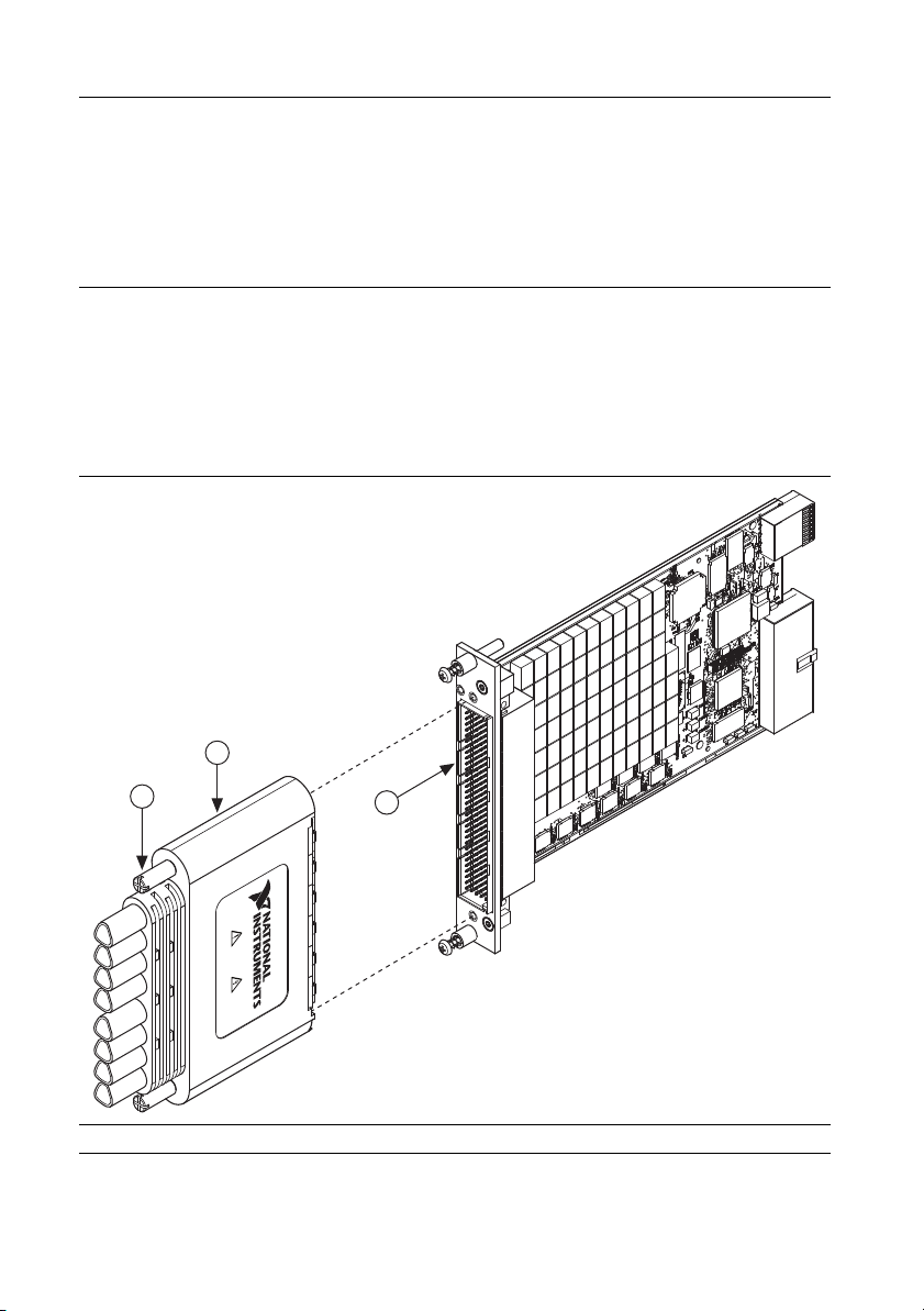
1. Connect the 160-Pin DIN connector to the NI 252x connector or NI 2510 connector on the
switch module as shown in Figure 1.
Figure 1. Connecting the 160-Pin DIN Connector to the NI 2520
1 Thumbscrews 2 160-Pin DIN Connector 3 NI PXI 2520 Connector
2 | ni.com | 160-Pin Cable Installation Instructions
Page 3

2. Tighten the thumbscrews on the cable.
3. Complete one of the following steps and refer to Tables 4 through 9 in the Cable
Configurations section to determine how to connect signals to your application.
• Connect the D-SUB connectors on the cable to your application. For screw terminal
access, you can connect directly to NI TBX-50 terminal blocks.
• Connect the second 160-Pin DIN connector on the cable to your application.
• Connect the unterminated wires to your application.
Figure 2. SH160DIN-4XDB50F-2A Cable
3
P1
1
2
NATIONAL INSTRUMENTS
150V
2
P2
P3
P4
4
1 160-Pin DIN Connector
2 Thumbscrews
3 Cable Leg Labels
4 50-Pin Female D-SUB Connectors
160-Pin Cable Installation Instructions | © National Instruments | 3
Page 4

Figure 3. SH160DIN-160DIN-2A Cable
NATIONAL INSTRUMENTS
150V
150V
2 2
1 1
P1
NATIONAL INSTRUMENTS
150V
P3
P4
P5
P6
P7
P8
P2
21
3 4
1 160-Pin DIN Connectors 2Thumbscrews
Figure 4. SH160DIN-BARE WIRE-2A Cable
1 160-Pin DIN Connector
2 Thumbscrews
3 Cable Leg Labels
4 20 Unterminated, Tinned, and Stripped Wires
4 | ni.com | 160-Pin Cable Installation Instructions
Page 5
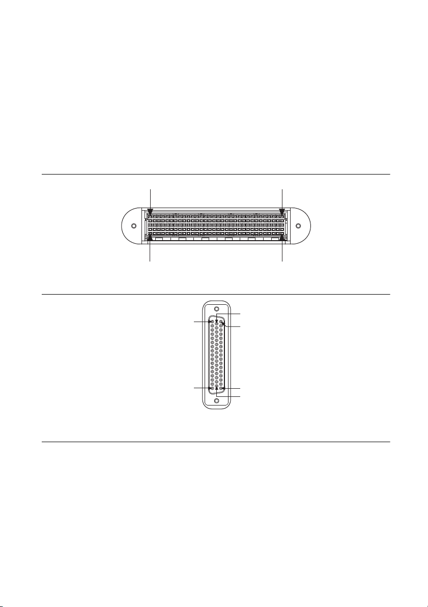
Connectors
PIN A32PIN A1
PIN E1 PIN E32
The cable connects a 160-Pin female DIN connector (DIN 160 connector) to the following:
• Four 50-pin female D-SUB connectors
• A second 160-Pin DIN connector
• Eight bundles, legs P1-P8, of unterminated, tinned, and stripped wires
The 160-Pin DIN connector provides connection to the NI 252x and NI 2510. The 50-pin female
D-SUB connectors, second 160-Pin DIN connector, and unterminated cables provide connection
to your application. Figures 5 and 6 show the pinouts for the 160-Pin DIN connectors and the
50-pin female D-SUB connectors.
Figure 5. 160-Pin DIN Mating Connector
Figure 6. 50-Pin Female D-SUB Connector
Pin 1
Pin 17
Cable Configurations
The 160-Pin DIN cable is available in three configurations:
• SH160DIN-4XDB50F-2A
• SH160DIN-160DIN-2A
• SH160DIN-BARE WIRE-2A
The following sections describe each of the configurations.
160-Pin Cable Installation Instructions | © National Instruments | 5
Pin 18
Pin 34
Pin 50
Pin 33
Page 6
SH160DIN-4XDB50F-2A Cable
The SH160DIN-4XDB50F-2A cable is recommended for connecting the NI 252x or NI 2510 to
your system. One end of the cable terminates with a 160-Pin DIN connector. The other end of
the cable terminates with four 50-pin female D-SUB connectors.
Use the pinouts and the pin assignments listed in Tables 1 through 4 to determine how to connect
signals to your application using the SH160DIN-4XDB50F-2A cable.
Refer to the NI Switches Help for a complete listing of channel names and pinouts.
Table 1. Pin Assignment for SH160DIN-4XDB50F-2A Connector P1
50-Pin D-SUB Connector P1
D-SUB
Pin
1 COM 17 CH 7+ NO 11 COM 6+ CH 15 A25
2 CH 17 CH 7- COM 11 COM 6- CH 14 B25
3 COM 18 CH 8+ NC 11 COM 7+ CH 13 C25
4 CH 18 CH 8- COM 13 COM 7- CH 12 D25
5 CH 19 CH 9- COM 14 NO 5- B2 E25
6 COM 15 COM 7+ NO 10 NO 6+ DUT 15 A26
7 CH 15 COM 7- COM 10 NO 6- DUT 14 B26
8 COM 16 COM 8+ NC 10 NO 7+ DUT 13 C26
9 CH 16 COM 8- NC 13 NO 7- DUT 12 D26
NI PXI-
2520
NI PXI-
2521
NI PXI-
2522
NI PXI-
2523
NI PXI-
2510
Interface
Connector
Pin
10 COM 19 CH 9+ NC 14 NO 5+ B1 E26
11 COM 12 CH 5+ NO 7 NC 3+ CH 11 A27
12 CH 12 CH 5- COM 7 NC 3- CH 10 B27
13 COM 13 CH 6+ NC 7 NC 4+ CH 9 C27
14 CH 13 CH 6- NC 8 NC 4- CH 8 D27
15 CH 14 COM 9- NC 9 NC 0- B0 E27
16 COM 10 COM 5+ NO 6 COM 3+ DUT 11 A28
17 CH 10 COM 5- COM 6 COM 3- DUT 10 B28
18 COM 11 COM 6+ NC 6 COM 4+ DUT 9 C28
19 CH 11 COM 6- COM 8 COM 4- DUT 8 D28
20 COM 14 COM 9+ COM 9 NC 0+ No Connect E28
6 | ni.com | 160-Pin Cable Installation Instructions
Page 7
Table 1. Pin Assignment for SH160DIN-4XDB50F-2A Connector P1 (Continued)
50-Pin D-SUB Connector P1
D-SUB
Pin
NI PXI-
2520
NI PXI-
2521
NI PXI-
2522
NI PXI-
2523
NI PXI-
2510
21 COM 7 CH 2+ NO 5 NO 3+ CH 7 A29
22 CH 7 CH 2- COM 5 NO 3- CH 6 B29
23 COM 8 CH 3+ NC 5 NO 4+ CH 5 C29
24 CH 8 CH 3- NO 8 NO 4- CH 4 D29
25 CH 9 CH 4- NO 9 COM 0- A3 E29
26 COM 5 COM 2+ NO 2 NC 1+ DUT 7 A30
27 CH 5 COM 2- COM 2 NC 1- DUT 6 B30
28 COM 6 COM 3+ NC 2 NC 2+ DUT 5 C30
29 CH 6 COM 3- NC 3 NC 2- DUT 4 D30
30 COM 9 CH 4+ NC 4 COM 0+ A2 E30
31 COM 2 CH 0+ NO 1 COM 1+ CH 3 A31
32 CH 2 CH 0- COM 1 COM 1- CH 2 B31
33 COM 3 CH 1+ NC 1 COM 2+ CH 1 C31
34 CH 3 CH 1- COM 3 COM 2- CH 0 D31
35 CH 4 COM 4- COM 4 NO 0- A1 E31
Interface
Connector
Pin
36 COM 0 COM 0+ NO 0 NO 1+ DUT 3 A32
37 CH 0 COM 0- COM 0 NO 1- DUT 2 B32
38 COM 1 COM 1+ NC 0 NO 2+ DUT 1 C32
39 CH 1 COM 1- NO 3 NO 2- DUT 0 D32
40 COM 4 COM 4+ NO 4 NO 0+ A0 E32
41 No Connect No Connect No Connect No Connect No Connect No Connect
42 No Connect No Connect No Connect No Connect No Connect No Connect
43 No Connect No Connect No Connect No Connect No Connect No Connect
44 No Connect No Connect No Connect No Connect No Connect No Connect
45 No Connect No Connect No Connect No Connect No Connect No Connect
46 No Connect No Connect No Connect No Connect No Connect No Connect
160-Pin Cable Installation Instructions | © National Instruments | 7
Page 8

Table 1. Pin Assignment for SH160DIN-4XDB50F-2A Connector P1 (Continued)
50-Pin D-SUB Connector P1
D-SUB
Pin
NI PXI-
2520
NI PXI-
2521
NI PXI-
2522
NI PXI-
2523
NI PXI-
2510
47 No Connect No Connect No Connect No Connect No Connect No Connect
48 No Connect No Connect No Connect No Connect No Connect No Connect
49 No Connect No Connect No Connect No Connect No Connect No Connect
50 No Connect No Connect No Connect No Connect No Connect No Connect
Interface
Connector
Pin
Table 2. Pin Assignment for SH160DIN-4XDB50F-2A Connector P2
50-Pin D-SUB Connector P2
D-SUB
Pin
NI PXI-
2520
NI PXI-
2521
NI PXI-
2522
NI PXI-
2523
NI PXI-
2510
1 COM 37 CH 17+ NO 25 NO 13+ CH 31 A17
2 CH 37 CH 17- COM 25 NO 13- CH 30 B17
3 COM 38 CH 18+ NC 25 NO 14+ CH 29 C17
4 CH 38 CH 18- NO 28 NO 14- CH 28 D17
Interface
Connector
Pin
5 CH 39 CH 19- NO 29 COM 10- No Connect E17
6 COM 35 COM 17+ NO 22 NC 11+ DUT 31 A18
7 CH 35 COM 17- COM 22 NC 11- DUT 30 B18
8 COM 36 COM 18+ NC 22 NC 12+ DUT 29 C18
9 CH 36 COM 18- NC 23 NC 12- DUT 28 D18
10 COM 39 CH 19+ NC 24 COM 10+ No Connect E18
11 COM 32 CH 15+ NO 21 COM 11+ CH 27 A19
12 CH 32 CH 15- COM 21 COM 11- CH 26 B19
13 COM 33 CH 16+ NC 21 COM 12+ CH 25 C19
14 CH 33 CH 16- COM 23 COM 12- CH 24 D19
15 CH 34 COM 19- COM 24 NO 10- No Connect E19
16 COM 30 COM 15+ NO 20 NO 11+ DUT 27 A20
17 CH 30 COM 15- COM 20 NO 11- DUT 26 B20
8 | ni.com | 160-Pin Cable Installation Instructions
Page 9
Table 2. Pin Assignment for SH160DIN-4XDB50F-2A Connector P2 (Continued)
50-Pin D-SUB Connector P2
D-SUB
Pin
NI PXI-
2520
NI PXI-
2521
NI PXI-
2522
NI PXI-
2523
NI PXI-
2510
18 COM 31 COM 16+ NC 20 NO 12+ DUT 25 C20
19 CH 31 COM 16- NO 23 NO 12- DUT 24 D20
20 COM 34 COM 19+ NO 24 NO 10+ No Connect E20
21 COM 27 CH 12+ NO 17 NC 8+ CH 23 A21
22 CH 27 CH 12- COM 17 NC 8- CH 22 B21
23 COM 28 CH 13+ NC 17 NC 9+ CH 21 C21
24 CH 28 CH 13- NO 18 NC 9- CH 20 D21
25 CH 29 CH 14- NO 19 NC 5- No Connect E21
26 COM 25 COM 12+ NO 16 COM 8+ DUT 23 A22
27 CH 25 COM 12- COM 16 COM 8- DUT 22 B22
28 COM 26 COM 13+ NC 16 COM 9+ DUT 21 C22
29 CH 26 COM 13- COM 18 COM 9- DUT 20 D22
30 COM 29 CH 14+ COM 19 NC 5+ No Connect E22
31 COM 22 CH 10+ NO 15 NO 8+ CH 19 A23
32 CH 22 CH 10- COM 15 NO 8- CH 18 B23
Interface
Connector
Pin
33 COM 23 CH 11+ NC 15 NO 9+ CH 17 C23
34 CH 23 CH 11- NC 18 NO 9- CH 16 D23
35 CH 24 COM 14- NC 19 COM 5- No Connect E23
36 COM 20 COM 10+ NO 12 NC 6+ DUT 19 A24
37 CH 20 COM 10- COM 12 NC 6- DUT 18 B24
38 COM 21 COM 11+ NC 12 NC 7+ DUT 17 C24
39 CH 21 COM 11- NO 13 NC 7- DUT 16 D24
40 COM 24 COM 14+ NO 14 COM 5+ B3 E24
41 No Connect No Connect No Connect No Connect No Connect No Connect
42 No Connect No Connect No Connect No Connect No Connect No Connect
43 No Connect No Connect No Connect No Connect No Connect No Connect
160-Pin Cable Installation Instructions | © National Instruments | 9
Page 10
Table 2. Pin Assignment for SH160DIN-4XDB50F-2A Connector P2 (Continued)
50-Pin D-SUB Connector P2
D-SUB
Pin
NI PXI-
2520
NI PXI-
2521
NI PXI-
2522
NI PXI-
2523
NI PXI-
2510
44 No Connect No Connect No Connect No Connect No Connect No Connect
45 No Connect No Connect No Connect No Connect No Connect No Connect
46 No Connect No Connect No Connect No Connect No Connect No Connect
47 No Connect No Connect No Connect No Connect No Connect No Connect
48 No Connect No Connect No Connect No Connect No Connect No Connect
49 No Connect No Connect No Connect No Connect No Connect No Connect
50 No Connect No Connect No Connect No Connect No Connect No Connect
Interface
Connector
Pin
Table 3. Pin Assignment for SH160DIN-4XDB50F-2A Connector P3
50-Pin D-SUB Connector P3
D-SUB
Pin
NI PXI-
2520
NI PXI-
2521
NI PXI-
2522
NI PXI-
2523
NI PXI-
2510
Connector
1 COM 57 CH 27+ NO 37 NC 18+ CH 47 A9
2 CH 57 CH 27- COM 37 NC 18- CH 46 B9
3 COM 58 CH 28+ NC 37 NC 19+ CH 45 C9
4 CH 58 CH 28- NO 38 NC 19- CH 44 D9
5 CH 59 CH 29- NO 39 NC 15- DUT 64 E9
6 COM 55 COM 27+ NO 36 COM 18+ DUT 47 A10
7 CH 55 COM 27- COM 36 COM 18- DUT 46 B10
8 COM 56 COM 28+ NC 36 COM 19+ DUT 45 C10
9 CH 56 COM 28- COM 38 COM 19- DUT 44 D10
10 COM 59 CH 29+ COM 39 NC 15+ No Connect E10
11 COM 52 CH 25+ NO 35 NO 18+ CH 43 A11
12 CH 52 CH 25- COM 35 NO 18- CH 42 B11
13 COM 53 CH 26+ NC 35 NO 19+ CH 41 C11
14 CH 53 CH 26- NC 38 NO 19- CH 40 D11
15 CH 54 COM 29- NC 39 COM 15- No Connect E11
Interface
Pin
10 | ni.com | 160-Pin Cable Installation Instructions
Page 11

Table 3. Pin Assignment for SH160DIN-4XDB50F-2A Connector P3 (Continued)
50-Pin D-SUB Connector P3
D-SUB
Pin
NI PXI-
2520
NI PXI-
2521
NI PXI-
2522
NI PXI-
2523
NI PXI-
2510
Connector
16 COM 50 COM 25+ NO 32 NC 16+ DUT 43 A12
17 CH 50 COM 25- COM 32 NC 16- DUT 42 B12
18 COM 51 COM 26+ NC 32 NC 17+ DUT 41 C12
19 CH 51 COM 26- NO 33 NC 17- DUT 40 D12
20 COM 54 COM 29+ NO 34 COM 15+ BUS B E12
21 COM 47 CH 22+ NO 31 COM 16+ CH 39 A13
22 CH 47 CH 22- COM 31 COM 16- CH 38 B13
23 COM 48 CH 23+ NC 31 COM 17+ CH 37 C13
24 CH 48 CH 23- COM 33 COM 17- CH 36 D13
25 CH 49 CH 24- COM 34 NO 15- No Connect E13
26 COM 45 COM 22+ NO 30 NO 16+ DUT 39 A14
27 CH 45 COM 22- COM 30 NO 16- DUT 38 B14
28 COM 46 COM 23+ NC 30 NO 17+ DUT 37 C14
29 CH 46 COM 23- NC 33 NO 17- DUT 36 D14
30 COM 49 CH 24+ NC 34 NO 15+ BUS A E14
31 COM 42 CH 20+ NO 27 NC 13+ CH 35 A15
Interface
Pin
32 CH 42 CH 20- COM 27 NC 13- CH 34 B15
33 COM 43 CH 21+ NC 27 NC 14+ CH 33 C15
34 CH 43 CH 21- NC 28 NC 14- CH 32 D15
35 CH 44 COM 24- NC 29 NC 10- No Connect E15
36 COM 40 COM 20+ NO 26 COM 13+ DUT 35 A16
37 CH 40 COM 20- COM 26 COM 13- DUT 34 B16
38 COM 41 COM 21+ NC 26 COM 14+ DUT 33 C16
39 CH 41 COM 21- COM 28 COM 14- DUT 32 D16
40 COM 44 COM 24+ COM 29 NC 10+ No Connect E16
41 No Connect No Connect No Connect No Connect No Connect No Connect
160-Pin Cable Installation Instructions | © National Instruments | 11
Page 12

Table 3. Pin Assignment for SH160DIN-4XDB50F-2A Connector P3 (Continued)
50-Pin D-SUB Connector P3
D-SUB
Pin
NI PXI-
2520
NI PXI-
2521
NI PXI-
2522
NI PXI-
2523
NI PXI-
2510
Interface
Connector
Pin
42 No Connect No Connect No Connect No Connect No Connect No Connect
43 No Connect No Connect No Connect No Connect No Connect No Connect
44 No Connect No Connect No Connect No Connect No Connect No Connect
45 No Connect No Connect No Connect No Connect No Connect No Connect
46 No Connect No Connect No Connect No Connect No Connect No Connect
47 No Connect No Connect No Connect No Connect No Connect No Connect
48 No Connect No Connect No Connect No Connect No Connect No Connect
49 No Connect No Connect No Connect No Connect No Connect No Connect
50 No Connect No Connect No Connect No Connect No Connect No Connect
Table 4. Pin Assignment for SH160DIN-4XDB50F-2A Connector P4
50-Pin D-SUB Connector P4
D-SUB
Pin
NI PXI-
2520
NI PXI-
2521
NI PXI-
2522
NI PXI-
2523
NI PXI-
2510
1 COM 77 CH 37+ NO 51 NO 25- CH 63 A1
Interface
Connector
Pin
2 CH 77 CH 37- COM 51 COM 25- CH 62 B1
3 COM 78 CH 38+ NC 51 NC 25- CH 61 C1
4 CH 78 CH 38- NC 52 No Connect CH 60 D1
5 CH 79 CH 39- No Connect No Connect Reserved E1
6 COM 75 COM 37+ NO 50 NO 25+ DUT 63 A2
7 CH 75 COM 37- COM 50 COM 25+ DUT 62 B2
8 COM 76 COM 38+ NC 50 NC 25+ DUT 61 C2
9 CH 76 COM 38- NO 52 No Connect DUT 60 D2
10 COM 79 CH 39+ COM 52 No Connect CH 67 E2
11 COM 72 CH 35+ NO 47 NC 23+ CH 59 A3
12 CH 72 CH 35- COM 47 NC 23- CH 58 B3
12 | ni.com | 160-Pin Cable Installation Instructions
Page 13

Table 4. Pin Assignment for SH160DIN-4XDB50F-2A Connector P4 (Continued)
50-Pin D-SUB Connector P4
D-SUB
Pin
NI PXI-
2520
NI PXI-
2521
NI PXI-
2522
NI PXI-
2523
NI PXI-
2510
Connector
13 COM 73 CH 36+ NC 47 NC 24+ CH 57 C3
14 CH 73 CH 36- NO 48 NC 24- CH 56 D3
15 CH 74 COM 39- NO 49 NC 20- DUT 67 E3
16 COM 70 COM 35+ NO 46 COM 23+ DUT 59 A4
17 CH 70 COM 35- COM 46 COM 23- DUT 58 B4
18 COM 71 COM 36+ NC 46 COM 24+ DUT 57 C4
19 CH 71 COM 36- COM 48 COM 24- DUT 56 D4
20 COM 74 COM 39+ COM 49 NC 20+ CH 66 E4
21 COM 67 CH 32+ NO 45 NO 23+ CH 55 A5
22 CH 67 CH 32- COM 45 NO 23- CH 54 B5
23 COM 68 CH 33+ NC 45 NO 24+ CH 53 C5
24 CH 68 CH 33- NC 48 NO 24- CH 52 D5
25 CH 69 CH 34- NC 49 COM 20- DUT 66 E5
26 COM 65 COM 32+ NO 42 NC 21+ DUT 55 A6
27 CH 65 COM 32- COM 42 NC 21- DUT 54 B6
28 COM 66 COM 33+ NC 42 NC 22+ DUT 53 C6
Interface
Pin
29 CH 66 COM 33- NC 43 NC 22- DUT 52 D6
30 COM 69 CH 34+ NC 44 COM 20+ CH 65 E6
31 COM 62 CH 30+ NO 41 COM 21+ CH 51 A7
32 CH 62 CH 30- COM 41 COM 21- CH 50 B7
33 COM 63 CH 31+ NC 41 COM 22+ CH 49 C7
34 CH 63 CH 31- COM 43 COM 22- CH 48 D7
35 CH 64 COM 34- COM 44 NO 20- DUT 65 E7
36 COM 60 COM 30+ NO 40 NO 21+ DUT 51 A8
37 CH 60 COM 30- COM 40 NO 21- DUT 50 B8
38 COM 61 COM 31+ NC 40 NO 22+ DUT 49 C8
160-Pin Cable Installation Instructions | © National Instruments | 13
Page 14

Table 4. Pin Assignment for SH160DIN-4XDB50F-2A Connector P4 (Continued)
50-Pin D-SUB Connector P4
D-SUB
Pin
39 CH 61 COM 31- NO 43 NO 22- DUT 48 D8
40 COM 64 COM 34+ NO 44 NO 20+ CH 64 E8
41 No Connect No Connect No Connect No Connect No Connect No Connect
42 No Connect No Connect No Connect No Connect No Connect No Connect
43 No Connect No Connect No Connect No Connect No Connect No Connect
44 No Connect No Connect No Connect No Connect No Connect No Connect
45 No Connect No Connect No Connect No Connect No Connect No Connect
46 No Connect No Connect No Connect No Connect No Connect No Connect
47 No Connect No Connect No Connect No Connect No Connect No Connect
48 No Connect No Connect No Connect No Connect No Connect No Connect
49 No Connect No Connect No Connect No Connect No Connect No Connect
50 No Connect No Connect No Connect No Connect No Connect No Connect
NI PXI-
2520
NI PXI-
2521
NI PXI-
2522
NI PXI-
2523
NI PXI-
2510
Interface
Connector
Pin
SH160DIN-160DIN-2A Cable
The SH160DIN-160DIN-2A cable is recommended for connecting the NI 252x or NI 2510 to a
system that terminates with a male 160-Pin DIN connector.
Use the pinouts and the pin assignments listed in Table 5 to determine how to connect signals to
your application using the SH160DIN-160DIN-2A cable.
Refer to the NI Switches Help for a complete listing of channel names and pinouts.
Table 5. Pin Assignment for the SH160DIN-160DIN-2A Cable
160DIN Mating Connector
NI PXI-2520 NI PXI-2521 NI PXI-2522 NI PXI-2523 NI PXI-2510
COM 77 CH 37+ NO 51 NO 25- CH 63 A1
CH 77 CH 37- COM 51 COM 25- CH 62 B1
COM 78 CH 38+ NC 51 NC 25- CH 61 C1
CH 78 CH 38- NC 52 No Connect CH 60 D1
14 | ni.com | 160-Pin Cable Installation Instructions
160 DIN
P1/P2 Pin
Page 15

Table 5. Pin Assignment for the SH160DIN-160DIN-2A Cable (Continued)
160DIN Mating Connector
NI PXI-2520 NI PXI-2521 NI PXI-2522 NI PXI-2523 NI PXI-2510
P1/P2 Pin
CH 79 CH 39- No Connect No Connect Reserved E1
COM 75 COM 37+ NO 50 NO 25+ DUT 63 A2
CH 75 COM 37- COM 50 COM 25+ DUT 62 B2
COM 76 COM 38+ NC 50 NC 25+ DUT 61 C2
CH 76 COM 38- NO 52 No Connect DUT 60 D2
COM 79 CH 39+ COM 52 No Connect CH 67 E2
COM 72 CH 35+ NO 47 NC 23+ CH 59 A3
CH 72 CH 35- COM 47 NC 23- CH 58 B3
COM 73 CH 36+ NC 47 NC 24+ CH 57 C3
CH 73 CH 36- NO 48 NC 24- CH 56 D3
CH 74 COM 39- NO 49 NC 20- DUT 67 E3
COM 70 COM 35+ NO 46 COM 23+ DUT 59 A4
CH 70 COM 35- COM 46 COM 23- DUT 58 B4
COM 71 COM 36+ NC 46 COM 24+ DUT 57 C4
CH 71 COM 36- COM 48 COM 24- DUT 56 D4
COM 74 COM 39+ COM 49 NC 20+ CH 66 E4
160 DIN
COM 67 CH 32+ NO 45 NO 23+ CH 55 A5
CH 67 CH 32- COM 45 NO 23- CH 54 B5
COM 68 CH 33+ NC 45 NO 24+ CH 53 C5
CH 68 CH 33- NC 48 NO 24- CH 52 D5
CH 69 CH 34- NC 49 COM 20- DUT 66 E5
COM 65 COM 32+ NO 42 NC 21+ DUT 55 A6
CH 65 COM 32- COM 42 NC 21- DUT 54 B6
COM 66 COM 33+ NC 42 NC 22+ DUT 53 C6
CH 66 COM 33- NC 43 NC 22- DUT 52 D6
COM 69 CH 34+ NC 44 COM 20+ CH 65 E6
COM 62 CH 30+ NO 41 COM 21+ CH 51 A7
160-Pin Cable Installation Instructions | © National Instruments | 15
Page 16

Table 5. Pin Assignment for the SH160DIN-160DIN-2A Cable (Continued)
160DIN Mating Connector
NI PXI-2520 NI PXI-2521 NI PXI-2522 NI PXI-2523 NI PXI-2510
P1/P2 Pin
CH 62 CH 30- COM 41 COM 21- CH 50 B7
COM 63 CH 31+ NC 41 COM 22+ CH 49 C7
CH 63 CH 31- COM 43 COM 22- CH 48 D7
CH 64 COM 34- COM 44 NO 20- DUT 65 E7
COM 60 COM 30+ NO 40 NO 21+ DUT 51 A8
CH 60 COM 30- COM 40 NO 21- DUT 50 B8
COM 61 COM 31+ NC 40 NO 22+ DUT 49 C8
CH 61 COM 31- NO 43 NO 22- DUT 48 D8
COM 64 COM 34+ NO 44 NO 20+ CH 64 E8
COM 57 CH 27+ NO 37 NC 18+ CH 47 A9
CH 57 CH 27- COM 37 NC 18- CH 46 B9
COM 58 CH 28+ NC 37 NC 19+ CH 45 C9
CH 58 CH 28- NO 38 NC 19- CH 44 D9
CH 59 CH 29- NO 39 NC 15- DUT 64 E9
COM 55 COM 27+ NO 36 COM 18+ DUT 47 A10
CH 55 COM 27- COM 36 COM 18- DUT 46 B10
160 DIN
COM 56 COM 28+ NC 36 COM 19+ DUT 45 C10
CH 56 COM 28- COM 38 COM 19- DUT 44 D10
COM 59 CH 29+ COM 39 NC 15+ No Connect E10
COM 52 CH 25+ NO 35 NO 18+ CH 43 A11
CH 52 CH 25- COM 35 NO 18- CH 42 B11
COM 53 CH 26+ NC 35 NO 19+ CH 41 C11
CH 53 CH 26- NC 38 NO 19- CH 40 D11
CH 54 COM 29- NC 39 COM 15- No Connect E11
COM 50 COM 25+ NO 32 NC 16+ DUT 43 A12
CH 50 COM 25- COM 32 NC 16- DUT 42 B12
COM 51 COM 26+ NC 32 NC 17+ DUT 41 C12
16 | ni.com | 160-Pin Cable Installation Instructions
Page 17

Table 5. Pin Assignment for the SH160DIN-160DIN-2A Cable (Continued)
160DIN Mating Connector
NI PXI-2520 NI PXI-2521 NI PXI-2522 NI PXI-2523 NI PXI-2510
P1/P2 Pin
CH 51 COM 26- NO 33 NC 17- DUT 40 D12
COM 54 COM 29+ NO 34 COM 15+ BUS B E12
COM 47 CH 22+ NO 31 COM 16+ CH 39 A13
CH 47 CH 22- COM 31 COM 16- CH 38 B13
COM 48 CH 23+ NC 31 COM 17+ CH 37 C13
CH 48 CH 23- COM 33 COM 17- CH 36 D13
CH 49 CH 24- COM 34 NO 15- No Connect E13
COM 45 COM 22+ NO 30 NO 16+ DUT 39 A14
CH 45 COM 22- COM 30 NO 16- DUT 38 B14
COM 46 COM 23+ NC 30 NO 17+ DUT 37 C14
CH 46 COM 23- NC 33 NO 17- DUT 36 D14
COM 49 CH 24+ NC 34 NO 15+ BUS A E14
COM 42 CH 20+ NO 27 NC 13+ CH 35 A15
CH 42 CH 20- COM 27 NC 13- CH 34 B15
COM 43 CH 21+ NC 27 NC 14+ CH 33 C15
CH 43 CH 21- NC 28 NC 14- CH 32 D15
160 DIN
CH 44 COM 24- NC 29 NC 10- No Connect E15
COM 40 COM 20+ NO 26 COM 13+ DUT 35 A16
CH 40 COM 20- COM 26 COM 13- DUT 34 B16
COM 41 COM 21+ NC 26 COM 14+ DUT 33 C16
CH 41 COM 21- COM 28 COM 14- DUT 32 D16
COM 44 COM 24+ COM 29 NC 10+ No Connect E16
COM 37 CH 17+ NO 25 NO 13+ CH 31 A17
CH 37 CH 17- COM 25 NO 13- CH 30 B17
COM 38 CH 18+ NC 25 NO 14+ CH 29 C17
CH 38 CH 18- NO 28 NO 14- CH 28 D17
CH 39 CH 19- NO 29 COM 10- No Connect E17
160-Pin Cable Installation Instructions | © National Instruments | 17
Page 18

Table 5. Pin Assignment for the SH160DIN-160DIN-2A Cable (Continued)
160DIN Mating Connector
NI PXI-2520 NI PXI-2521 NI PXI-2522 NI PXI-2523 NI PXI-2510
P1/P2 Pin
COM 35 COM 17+ NO 22 NC 11+ DUT 31 A18
CH 35 COM 17- COM 22 NC 11- DUT 30 B18
COM 36 COM 18+ NC 22 NC 12+ DUT 29 C18
CH 36 COM 18- NC 23 NC 12- DUT 28 D18
COM 39 CH 19+ NC 24 COM 10+ No Connect E18
COM 32 CH 15+ NO 21 COM 11+ CH 27 A19
CH 32 CH 15- COM 21 COM 11- CH 26 B19
COM 33 CH 16+ NC 21 COM 12+ CH 25 C19
CH 33 CH 16- COM 23 COM 12- CH 24 D19
CH 34 COM 19- COM 24 NO 10- No Connect E19
COM 30 COM 15+ NO 20 NO 11+ DUT 27 A20
CH 30 COM 15- COM 20 NO 11- DUT 26 B20
COM 31 COM 16+ NC 20 NO 12+ DUT 25 C20
CH 31 COM 16- NO 23 NO 12- DUT 24 D20
COM 34 COM 19+ NO 24 NO 10+ No Connect E20
COM 27 CH 12+ NO 17 NC 8+ CH 23 A21
160 DIN
CH 27 CH 12- COM 17 NC 8- CH 22 B21
COM 28 CH 13+ NC 17 NC 9+ CH 21 C21
CH 28 CH 13- NO 18 NC 9- CH 20 D21
CH 29 CH 14- NO 19 NC 5- No Connect E21
COM 25 COM 12+ NO 16 COM 8+ DUT 23 A22
CH 25 COM 12- COM 16 COM 8- DUT 22 B22
COM 26 COM 13+ NC 16 COM 9+ DUT 21 C22
CH 26 COM 13- COM 18 COM 9- DUT 20 D22
COM 29 CH 14+ COM 19 NC 5+ No Connect E22
COM 22 CH 10+ NO 15 NO 8+ CH 19 A23
CH 22 CH 10- COM 15 NO 8- CH 18 B23
18 | ni.com | 160-Pin Cable Installation Instructions
Page 19

Table 5. Pin Assignment for the SH160DIN-160DIN-2A Cable (Continued)
160DIN Mating Connector
NI PXI-2520 NI PXI-2521 NI PXI-2522 NI PXI-2523 NI PXI-2510
P1/P2 Pin
COM 23 CH 11+ NC 15 NO 9+ CH 17 C23
CH 23 CH 11- NC 18 NO 9- CH 16 D23
CH 24 COM 14- NC 19 COM 5- No Connect E23
COM 20 COM 10+ NO 12 NC 6+ DUT 19 A24
CH 20 COM 10- COM 12 NC 6- DUT 18 B24
COM 21 COM 11+ NC 12 NC 7+ DUT 17 C24
CH 21 COM 11- NO 13 NC 7- DUT 16 D24
COM 24 COM 14+ NO 14 COM 5+ B3 E24
COM 17 CH 7+ NO 11 COM 6+ CH 15 A25
CH 17 CH 7- COM 11 COM 6- CH 14 B25
COM 18 CH 8+ NC 11 COM 7+ CH 13 C25
CH 18 CH 8- COM 13 COM 7- CH 12 D25
CH 19 CH 9- COM 14 NO 5- B2 E25
COM 15 COM 7+ NO 10 NO 6+ DUT 15 A26
CH 15 COM 7- COM 10 NO 6- DUT 14 B26
COM 16 COM 8+ NC 10 NO 7+ DUT 13 C26
160 DIN
CH 16 COM 8- NC 13 NO 7- DUT 12 D26
COM 19 CH 9+ NC 14 NO 5+ B1 E26
COM 12 CH 5+ NO 7 NC 3+ CH 11 A27
CH 12 CH 5- COM 7 NC 3- CH 10 B27
COM 13 CH 6+ NC 7 NC 4+ CH 9 C27
CH 13 CH 6- NC 8 NC 4- CH 8 D27
CH 14 COM 9- NC 9 NC 0- B0 E27
COM 10 COM 5+ NO 6 COM 3+ DUT 11 A28
CH 10 COM 5- COM 6 COM 3- DUT 10 B28
COM 11 COM 6+ NC 6 COM 4+ DUT 9 C28
CH 11 COM 6- COM 8 COM 4- DUT 8 D28
160-Pin Cable Installation Instructions | © National Instruments | 19
Page 20

Table 5. Pin Assignment for the SH160DIN-160DIN-2A Cable (Continued)
160DIN Mating Connector
NI PXI-2520 NI PXI-2521 NI PXI-2522 NI PXI-2523 NI PXI-2510
P1/P2 Pin
COM 14 COM 9+ COM 9 NC 0+ No Connect E28
COM 7 CH 2+ NO 5 NO 3+ CH 7 A29
CH 7 CH 2- COM 5 NO 3- CH 6 B29
COM 8 CH 3+ NC 5 NO 4+ CH 5 C29
CH 8 CH 3- NO 8 NO 4- CH 4 D29
CH 9 CH 4- NO 9 COM 0- A3 E29
COM 5 COM 2+ NO 2 NC 1+ DUT 7 A30
CH 5 COM 2- COM 2 NC 1- DUT 6 B30
COM 6 COM 3+ NC 2 NC 2+ DUT 5 C30
CH 6 COM 3- NC 3 NC 2- DUT 4 D30
COM 9 CH 4+ NC 4 COM 0+ A2 E30
COM 2 CH 0+ NO 1 COM 1+ CH 3 A31
CH 2 CH 0- COM 1 COM 1- CH 2 B31
COM 3 CH 1+ NC 1 COM 2+ CH 1 C31
CH 3 CH 1- COM 3 COM 2- CH 0 D31
CH 4 COM 4- COM 4 NO 0- A1 E31
160 DIN
COM 0 COM 0+ NO 0 NO 1+ DUT 3 A32
CH 0 COM 0- COM 0 NO 1- DUT 2 B32
COM 1 COM 1+ NC 0 NO 2+ DUT 1 C32
CH 1 COM 1- NO 3 NO 2- DUT 0 D32
COM 4 COM 4+ NO 4 NO 0+ A0 E32
20 | ni.com | 160-Pin Cable Installation Instructions
Page 21

SH160DIN-BARE WIRE-2A Cable
The SH160DIN-BARE WIRE-2A cable is recommended for connecting the NI 252x or the
NI 2510 to your system if termination with a connector other than a 50-pin female D-SUB or
160-Pin DIN connector is required. One end of the cable terminates with a 160-Pin DIN
connector. The other end of the cable has eight bundles of unterminated, tinned, and stripped
wires.
Use the pinouts and the pin assignments listed in Tables 6 through 13 to determine how to
connect signals to your application.
Note The first color listed in the Bare Wire Color column of Tables 6 through 13 is
the primary color of the wire. The second color listed is the stripe color.
Table 6. Pin Assignment for SH160DIN-BARE WIRE-2A Cable Leg P1
Cable Leg P1
Bare Wire
Color
BLACK COM 7 CH 2+ NO 5 NO 3+ CH 7 A29
BROWN CH 7 CH 2- COM 5 NO 3- CH 6 B29
RED COM 8 CH 3+ NC 5 NO 4+ CH 5 C29
ORANGE CH 8 CH 3- NO 8 NO 4- CH 4 D29
YELLOW CH 9 CH 4- NO 9 COM 0- A3 E29
GREEN COM 5 COM 2+ NO 2 NC 1+ DUT 7 A30
BLUE CH 5 COM 2- COM 2 NC 1- DUT 6 B30
PURPLE COM 6 COM 3+ NC 2 NC 2+ DUT 5 C30
GRAY CH 6 COM 3- NC 3 NC 2- DUT 4 D30
WHITE COM 9 CH 4+ NC 4 COM 0+ A2 E30
PINK COM 2 CH 0+ NO 1 COM 1+ CH 3 A31
LIGHT
GREEN
BLACK/
WHITE
BROWN/
WHITE
RED/
WHITE
NI PXI-
2520
CH 2 CH 0- COM 1 COM 1- CH 2 B31
COM 3 CH 1+ NC 1 COM 2+ CH 1 C31
CH 3 CH 1- COM 3 COM 2- CH 0 D31
CH 4 COM 4- COM 4 NO 0- A1 E31
NI PXI-
2521
NI PXI-
2522
NI PXI-
2523
NI PXI-
2510
Interface
Connector
Pin
160-Pin Cable Installation Instructions | © National Instruments | 21
Page 22

Table 6. Pin Assignment for SH160DIN-BARE WIRE-2A Cable Leg P1 (Continued)
Cable Leg P1
Bare Wire
Color
ORANGE/
NI PXI-
2520
NI PXI-
2521
NI PXI-
2522
NI PXI-
2523
NI PXI-
2510
COM 0 COM 0+ NO 0 NO 1+ DUT 3 A32
Interface
Connector
Pin
WHITE
GREEN/
CH 0 COM 0- COM 0 NO 1- DUT 2 B32
WHITE
BLUE/
COM 1 COM 1+ NC 0 NO 2+ DUT 1 C32
WHITE
PURPLE/
CH 1 COM 1- NO 3 NO 2- DUT 0 D32
WHITE
RED/
COM 4 COM 4+ NO 4 NO 0+ A0 E32
BLACK
Table 7. Pin Assignment for SH160DIN-BARE WIRE-2A Cable Leg P2
Cable Leg P2
Bare Wire
Color
NI PXI-
2520
NI PXI-
2521
NI PXI-
2522
NI PXI-
2523
NI PXI-
2510
Interface
Connector
Pin
BLACK COM 17 CH 7+ NO 11 COM 6+ CH 15 A25
BROWN CH 17 CH 7- COM 11 COM 6- CH 14 B25
RED COM 18 CH 8+ NC 11 COM 7+ CH 13 C25
ORANGE CH 18 CH 8- COM 13 COM 7- CH 12 D25
YELLOW CH 19 CH 9- COM 14 NO 5- B2 E25
GREEN COM 15 COM 7+ NO 10 NO 6+ DUT 15 A26
BLUE CH 15 COM 7- COM 10 NO 6- DUT 14 B26
PURPLE COM 16 COM 8+ NC 10 NO 7+ DUT 13 C26
GRAY CH 16 COM 8- NC 13 NO 7- DUT 12 D26
WHITE COM 19 CH 9+ NC 14 NO 5+ B1 E26
PINK COM 12 CH 5+ NO 7 NC 3+ CH 11 A27
LIGHT
CH 12 CH 5- COM 7 NC 3- CH 10 B27
GREEN
BLACK/
COM 13 CH 6+ NC 7 NC 4+ CH 9 C27
WHITE
22 | ni.com | 160-Pin Cable Installation Instructions
Page 23

Table 7. Pin Assignment for SH160DIN-BARE WIRE-2A Cable Leg P2 (Continued)
Cable Leg P2
Bare Wire
Color
BROWN/
NI PXI-
2520
NI PXI-
2521
NI PXI-
2522
NI PXI-
2523
NI PXI-
2510
CH 13 CH 6- NC 8 NC 4- CH 8 D27
Interface
Connector
Pin
WHITE
RED/
CH 14 COM 9- NC 9 NC 0- B0 E27
WHITE
ORANGE/
COM 10 COM 5+ NO 6 COM 3+ DUT 11 A28
WHITE
GREEN/
CH 10 COM 5- COM 6 COM 3- DUT 10 B28
WHITE
BLUE/
COM 11 COM 6+ NC 6 COM 4+ DUT 9 C28
WHITE
PURPLE/
CH 11 COM 6- COM 8 COM 4- DUT 8 D28
WHITE
RED/
BLACK
COM 14 COM 9+ COM 9 NC 0+ No
Connect
E28
Table 8. Pin Assignment for SH160DIN-BARE WIRE-2A Cable Leg P3
Cable Leg P3
Bare Wire
Color
NI PXI-
2520
NI PXI-
2521
NI PXI-
2522
NI PXI-
2523
NI PXI-
2510
Interface
Connector
Pin
BLACK COM 27 CH 12+ NO 17 NC 8+ CH 23 A21
BROWN CH 27 CH 12- COM 17 NC 8- CH 22 B21
RED COM 28 CH 13+ NC 17 NC 9+ CH 21 C21
ORANGE CH 28 CH 13- NO 18 NC 9- CH 20 D21
YELLOW CH 29 CH 14- NO 19 NC 5- No Connect E21
GREEN COM 25 COM 12+ NO 16 COM 8+ DUT 23 A22
BLUE CH 25 COM 12- COM 16 COM 8- DUT 22 B22
PURPLE COM 26 COM 13+ NC 16 COM 9+ DUT 21 C22
GRAY CH 26 COM 13- COM 18 COM 9- DUT 20 D22
WHITE COM 29 CH 14+ COM 19 NC 5+ No Connect E22
160-Pin Cable Installation Instructions | © National Instruments | 23
Page 24

Table 8. Pin Assignment for SH160DIN-BARE WIRE-2A Cable Leg P3 (Continued)
Cable Leg P3
Bare Wire
Color
NI PXI-
2520
NI PXI-
2521
NI PXI-
2522
NI PXI-
2523
NI PXI-
2510
Interface
Connector
Pin
PINK COM 22 CH 10+ NO 15 NO 8+ CH 19 A23
LIGHT
CH 22 CH 10- COM 15 NO 8- CH 18 B23
GREEN
BLACK/
COM 23 CH 11+ NC 15 NO 9+ CH 17 C23
WHITE
BROWN/
CH 23 CH 11- NC 18 NO 9- CH 16 D23
WHITE
RED/
CH 24 COM 14- NC 19 COM 5- No Connect E23
WHITE
ORANGE/
COM 20 COM 10+ NO 12 NC 6+ DUT 19 A24
WHITE
GREEN/
CH 20 COM 10- COM 12 NC 6- DUT 18 B24
WHITE
BLUE/
COM 21 COM 11+ NC 12 NC 7+ DUT 17 C24
WHITE
PURPLE/
CH 21 COM 11- NO 13 NC 7- DUT 16 D24
WHITE
RED/
COM 24 COM 14+ NO 14 COM 5+ B3 E24
BLACK
Table 9. Pin Assignment for SH160DIN-BARE WIRE-2A Cable Leg P4
Cable Leg P4
Bare Wire
Color
NI PXI-
2520
NI PXI-
2521
NI PXI-
2522
NI PXI-
2523
NI PXI-
2510
Interface
Connector
BLACK COM 37 CH 17+ NO 25 NO 13+ CH 31 A17
BROWN CH 37 CH 17- COM 25 NO 13- CH 30 B17
RED COM 38 CH 18+ NC 25 NO 14+ CH 29 C17
ORANGE CH 38 CH 18- NO 28 NO 14- CH 28 D17
YELLOW CH 39 CH 19- NO 29 COM 10- No Connect E17
GREEN COM 35 COM 17+ NO 22 NC 11+ DUT 31 A18
24 | ni.com | 160-Pin Cable Installation Instructions
Pin
Page 25

Table 9. Pin Assignment for SH160DIN-BARE WIRE-2A Cable Leg P4 (Continued)
Cable Leg P4
Bare Wire
Color
NI PXI-
2520
NI PXI-
2521
NI PXI-
2522
NI PXI-
2523
NI PXI-
2510
Interface
Connector
Pin
BLUE CH 35 COM 17- COM 22 NC 11- DUT 30 B18
PURPLE COM 36 COM 18+ NC 22 NC 12+ DUT 29 C18
GRAY CH 36 COM 18- NC 23 NC 12- DUT 28 D18
WHITE COM 39 CH 19+ NC 24 COM 10+ No Connect E18
PINK COM 32 CH 15+ NO 21 COM 11+ CH 27 A19
LIGHT
CH 32 CH 15- COM 21 COM 11- CH 26 B19
GREEN
BLACK/
COM 33 CH 16+ NC 21 COM 12+ CH 25 C19
WHITE
BROWN/
CH 33 CH 16- COM 23 COM 12- CH 24 D19
WHITE
RED/
CH 34 COM 19- COM 24 NO 10- No Connect E19
WHITE
ORANGE/
COM 30 COM 15+ NO 20 NO 11+ DUT 27 A20
WHITE
GREEN/
CH 30 COM 15- COM 20 NO 11- DUT 26 B20
WHITE
BLUE/
COM 31 COM 16+ NC 20 NO 12+ DUT 25 C20
WHITE
PURPLE/
CH 31 COM 16- NO 23 NO 12- DUT 24 D20
WHITE
RED/
COM 34 COM 19+ NO 24 NO 10+ No Connect E20
BLACK
Table 10. Pin Assignment for SH160DIN-BARE WIRE-2A Cable Leg P5
Cable Leg P5
Bare Wire
Color
NI PXI-
2520
NI PXI-
2521
NI PXI-
2522
NI PXI-
2523
NI PXI-
2510
Interface
Connector
Pin
BLACK COM 47 CH 22+ NO 31 COM 16+ CH 39 A13
BROWN CH 47 CH 22- COM 31 COM 16- CH 38 B13
160-Pin Cable Installation Instructions | © National Instruments | 25
Page 26

Table 10. Pin Assignment for SH160DIN-BARE WIRE-2A Cable Leg P5 (Continued)
Cable Leg P5
Bare Wire
Color
NI PXI-
2520
NI PXI-
2521
NI PXI-
2522
NI PXI-
2523
NI PXI-
2510
Interface
Connector
Pin
RED COM 48 CH 23+ NC 31 COM 17+ CH 37 C13
ORANGE CH 48 CH 23- COM 33 COM 17- CH 36 D13
YELLOW CH 49 CH 24- COM 34 NO 15- No Connect E13
GREEN COM 45 COM 22+ NO 30 NO 16+ DUT 39 A14
BLUE CH 45 COM 22- COM 30 NO 16- DUT 38 B14
PURPLE COM 46 COM 23+ NC 30 NO 17+ DUT 37 C14
GRAY CH 46 COM 23- NC 33 NO 17- DUT 36 D14
WHITE COM 49 CH 24+ NC 34 NO 15+ BUS_A E14
PINK COM 42 CH 20+ NO 27 NC 13+ CH 35 A15
LIGHT
GREEN
BLACK/
WHITE
BROWN/
WHITE
RED/
WHITE
ORANGE/
WHITE
GREEN/
WHITE
BLUE/
WHITE
PURPLE/
WHITE
RED/
BLACK
CH 42 CH 20- COM 27 NC 13- CH 34 B15
COM 43 CH 21+ NC 27 NC 14+ CH 33 C15
CH 43 CH 21- NC 28 NC 14- CH 32 D15
CH 44 COM 24- NC 29 NC 10- No Connect E15
COM 40 COM 20+ NO 26 COM 13+ DUT 35 A16
CH 40 COM 20- COM 26 COM 13- DUT 34 B16
COM 41 COM 21+ NC 26 COM 14+ DUT 33 C16
CH 41 COM 21- COM 28 COM 14- DUT 32 D16
COM 44 COM 24+ COM 29 NC 10+ No Connect E16
26 | ni.com | 160-Pin Cable Installation Instructions
Page 27

Table 11. Pin Assignment for SH160DIN-BARE WIRE-2A Cable Leg P6
Cable Leg P6
Bare Wire
Color
NI PXI-
2520
NI PXI-
2521
NI PXI-
2522
NI PXI-
2523
NI PXI-
2510
Interface
Connector
Pin
BLACK COM 57 CH 27+ NO 37 NC 18+ CH 47 A9
BROWN CH 57 CH 27- COM 37 NC 18- CH 46 B9
RED COM 58 CH 28+ NC 37 NC 19+ CH 45 C9
ORANGE CH 58 CH 28- NO 38 NC 19- CH 44 D9
YELLOW CH 59 CH 29- NO 39 NC 15- DUT 64 E9
GREEN COM 55 COM 27+ NO 36 COM 18+ DUT 47 A10
BLUE CH 55 COM 27- COM 36 COM 18- DUT 46 B10
PURPLE COM 56 COM 28+ NC 36 COM 19+ DUT 45 C10
GRAY CH 56 COM 28- COM 38 COM 19- DUT 44 D10
WHITE COM 59 CH 29+ COM 39 NC 15+ No Connect E10
PINK COM 52 CH 25+ NO 35 NO 18+ CH 43 A11
LIGHT
CH 52 CH 25- COM 35 NO 18- CH 42 B11
GREEN
BLACK/
COM 53 CH 26+ NC 35 NO 19+ CH 41 C11
WHITE
BROWN/
CH 53 CH 26- NC 38 NO 19- CH 40 D11
WHITE
RED/
CH 54 COM 29- NC 39 COM 15- No Connect E11
WHITE
ORANGE/
COM 50 COM 25+ NO 32 NC 16+ DUT 43 A12
WHITE
GREEN/
WHITE
BLUE/
WHITE
PURPLE/
WHITE
RED/
BLACK
CH 50 COM 25- COM 32 NC 16- DUT 42 B12
COM 51 COM 26+ NC 32 NC 17+ DUT 41 C12
CH 51 COM 26- NO 33 NC 17- DUT 40 D12
COM 54 COM 29+ NO 34 COM 15+ BUS_B E12
160-Pin Cable Installation Instructions | © National Instruments | 27
Page 28

Table 12. Pin Assignment for SH160DIN-BARE WIRE-2A Cable Leg P7
Cable Leg P7
Bare Wire
Color
NI PXI-
2520
NI PXI-
2521
NI PXI-
2522
NI PXI-
2523
NI PXI-
2510
Interface
Connector
Pin
BLACK COM 67 CH 32+ NO 45 NO 23+ CH 55 A5
BROWN CH 67 CH 32- COM 45 NO 23- CH 54 B5
RED COM 68 CH 33+ NC 45 NO 24+ CH 53 C5
ORANGE CH 68 CH 33- NC 48 NO 24- CH 52 D5
YELLOW CH 69 CH 34- NC 49 COM 20- DUT 66 E5
GREEN COM 65 COM 32+ NO 42 NC 21+ DUT 55 A6
BLUE CH 65 COM 32- COM 42 NC 21- DUT 54 B6
PURPLE COM 66 COM 33+ NC 42 NC 22+ DUT 53 C6
GRAY CH 66 COM 33- NC 43 NC 22- DUT 52 D6
WHITE COM 69 CH 34+ NC 44 COM 20+ CH 65 E6
PINK COM 62 CH 30+ NO 41 COM 21+ CH 51 A7
LIGHT
CH 62 CH 30- COM 41 COM 21- CH 50 B7
GREEN
BLACK/
COM 63 CH 31+ NC 41 COM 22+ CH 49 C7
WHITE
BROWN/
CH 63 CH 31- COM 43 COM 22- CH 48 D7
WHITE
RED/
CH 64 COM 34- COM 44 NO 20- DUT 65 E7
WHITE
ORANGE/
COM 60 COM 30+ NO 40 NO 21+ DUT 51 A8
WHITE
GREEN/
CH 60 COM 30- COM 40 NO 21- DUT 50 B8
WHITE
BLUE/
COM 61 COM 31+ NC 40 NO 22+ DUT 49 C8
WHITE
PURPLE/
CH 61 COM 31- NO 43 NO 22- DUT 48 D8
WHITE
RED/
COM 64 COM 34+ NO 44 NO 20+ CH 64 E8
BLACK
28 | ni.com | 160-Pin Cable Installation Instructions
Page 29

Table 13. Pin Assignment for SH160DIN-BARE WIRE-2A Cable Leg P8
Cable Leg P8
Bare Wire
Color
NI PXI-
2520
NI PXI-
2521
NI PXI-
2522
NI PXI-
2523
NI PXI-
2510
Interface
Connector
Pin
BLACK COM 77 CH 37+ NO 51 NO 25- CH 63 A1
BROWN CH 77 CH 37- COM 51 COM 25- CH 62 B1
RED COM 78 CH 38+ NC 51 NC 25- CH 61 C1
ORANGE CH 78 CH 38- NC 52 No Connect CH 60 D1
YELLOW CH 79 CH 39- No Connect No Connect Reserved E1
GREEN COM 75 COM 37+ NO 50 NO 25+ DUT 63 A2
BLUE CH 75 COM 37- COM 50 COM 25+ DUT 62 B2
PURPLE COM 76 COM 38+ NC 50 NC 25+ DUT 61 C2
GRAY CH 76 COM 38- NO 52 No Connect DUT 60 D2
WHITE COM 79 CH 39+ COM 52 No Connect CH 67 E2
PINK COM 72 CH 35+ NO 47 NC 23+ CH 59 A3
LIGHT
CH 72 CH 35- COM 47 NC 23- CH 58 B3
GREEN
BLACK/
COM 73 CH 36+ NC 47 NC 24+ CH 57 C3
WHITE
BROWN/
CH 73 CH 36- NO 48 NC 24- CH 56 D3
WHITE
RED/
CH 74 COM 39- NO 49 NC 20- DUT 67 E3
WHITE
ORANGE/
COM 70 COM 35+ NO 46 COM 23+ DUT 59 A4
WHITE
GREEN/
WHITE
BLUE/
WHITE
PURPLE/
WHITE
RED/
BLACK
CH 70 COM 35- COM 46 COM 23- DUT 58 B4
COM 71 COM 36+ NC 46 COM 24+ DUT 57 C4
CH 71 COM 36- COM 48 COM 24- DUT 56 D4
COM 74 COM 39+ COM 49 NC 20+ CH 66 E4
160-Pin Cable Installation Instructions | © National Instruments | 29
Page 30

Specifications
Maximum voltage ............................................. 150 V, CAT I
Maximum current per pin ................................. 2 A
Caution Do not connect to mains supply circuits (e.g., wall outlets) of 115 or
230 VAC. Refer to the Read Me First: Safety and Electromagnetic Compatibility
document for more information about Measurement Categories.
Weight
SH160DIN-4XDB50F-2A........................1837.1 g (64.8 oz)
SH160DIN-160DIN-2A............................1564.9 g (55. 1 oz)
SH160DIN-BARE WIRE-2A...................1451.5 g (51.2 oz)
Environment
Operating temperature ......................................0 °C to 55 °C
Storage temperature .......................................... -20 °C to 70 °C
Relative humidity.............................................. 5% to 85%, noncondensing
Pollution Degree ............................................... 2
Maximum altitude............................................. 2,000 m
Indoor use only.
Accessories
Visit ni.com for information about the following accessory.
Caution This product must be operated with shielded accessories to ensure
compliance with Electromagnetic Compatibility (EMC) requirements. Do not
use unshielded terminal blocks (such as the NI TBX-50B) or other unshielded
accessories unless they are installed in a shielded enclosure with properly designed
and shielded input/output ports and connected to the NI product(s) using a shielded
cable. If unshielded cables or accessories are not properly installed and shielded, the
EMC specifications for the product are no longer guaranteed.
Table 14. NI Accessory for the 160-Pin DIN Cable
Accessory Part Number
NI TBX-50B terminal block, with screw connection and
50 position D-Subminiature pin strip
30 | ni.com | 160-Pin Cable Installation Instructions
782866-01
Page 31

Caution You must install mating connectors according to local safety codes
and standards and according to the specifications provided by the connector
manufacturer. You are responsible for verifying safety compliance of third-party
connectors and their usage according to the relevant standard(s), including UL and
CSA in North America and IEC and VDE in Europe.
Refer to Table 15 for information about third-party accessories.
Table 15. Third-Party Accessories for the 160-Pin DIN Cable
Accessory Manufacturer Part Number
VARIOFACE module, with screw connection and
50 position D-Subminiature male connector
Right-angle 50 position male D-SUB connector
*
Small quantity orders are available from Digi-Key Corporation (part number A23398-ND).
*
Phoenix
Contact
Amp 747497-4
FLK-D50 SUB/S
Compliance and Certifications
Safety
This product is designed to meet the requirements of the following electrical equipment safety
standards for measurement, control, and laboratory use:
• IEC 61010-1, EN 61010-1
• UL 61010-1, CSA 61010-1
Note For EMC declarations and certifications, and additional information, refer to
the Online Product Certification section.
CE Compliance
This product meets the essential requirements of applicable European Directives as follows:
• 2006/95/EC; Low-Voltage Directive (safety)
Online Product Certification
To obtain product certifications and the Declaration of Conformity (DoC) for this product, visit
ni.com/certification, search by model number or product line, and click the appropriate
link in the Certification column.
160-Pin Cable Installation Instructions | © National Instruments | 31
Page 32

Environmental Management
⬉ᄤֵᙃѻક∵ᶧࠊㅵ⧚ࡲ⊩ ˄Ё
RoHS
˅
Ёᅶ᠋
National Instruments
ヺড়Ё⬉ᄤֵᙃѻકЁ䰤ࠊՓ⫼ᶤѯ᳝ᆇ⠽䋼ᣛҸ
(RoHS)
DŽ݇Ѣ
National InstrumentsЁRoHS
ড়㾘ᗻֵᙃˈ䇋ⱏᔩ
ni.com/
environment/rohs_china
DŽ
(For information about China RoHS compliance,
go to
ni.com/environment/rohs_china
.)
NI is committed to designing and manufacturing products in an environmentally responsible
manner. NI recognizes that eliminating certain hazardous substances from our products is
beneficial to the environment and to NI customers.
For additional environmental information, refer to the Minimize Our Environmental Impact web
ni.com/environment. This page contains the environmental regulations and
page at
directives with which NI complies, as well as other environmental information not included in
this document.
Waste Electrical and Electronic Equipment (WEEE)
EU Customers At the end of the product life cycle, all products must be sent to
a WEEE recycling center. For more information about WEEE recycling centers,
National Instruments WEEE initiatives, and compliance with WEEE Directive
2002/96/EC on Waste and Electronic Equipment, visit
.
weee
ni.com/environment/
Where to Go for Support
The National Instruments website is your complete resource for technical support. At ni.com/
support
self-help resources to email and phone assistance from NI Application Engineers.
you have access to everything from troubleshooting and application development
National Instruments corporate headquarters is located at 11500 North Mopac Expressway,
Austin, Texas, 78759-3504. National Instruments also has offices located around the world. For
telephone support in the United States, create your service request at
512 795 8248. For telephone support outside the United States, visit the Worldwide Offices
section of
ni.com/niglobal to access the branch office websites, which provide up-to-date
contact information, support phone numbers, email addresses, and current events.
Refer to the NI Trademarks and Logo Guidelines at ni.com/trademarks for more information on National Instruments trademarks. Other
product and company names mentioned herein are trademarks or trade names of their respective companies. For patents covering National
Instruments products/technology, refer to the appropriate location: Help»Patents in your software, the patents.txt file on your media, or the
National Instruments Patents Notice at ni.com/patents. You can find information about end-user license agreements (EULAs) and third-party
legal notices in the readme file for your NI product. Refer to the Export Compliance Information at ni.com/legal/export-compliance
for the National Instruments global trade compliance policy and how to obtain relevant HTS codes, ECCNs, and other import/export data.
© 2013 National Instruments. All rights reserved.
375965B-01 Dec13
ni.com/support or dial
 Loading...