

Page 1

TM
SCXI
SCXI-1520 User Manual
SCXI-1520 User Manual
May 2009
372583E-01
Page 2

Support
Worldwide Technical Support and Product Information
ni.com
National Instruments Corporate Headquarters
11500 North Mopac Expressway Austin, Texas 78759-3504 USA Tel: 512 683 0100
Worldwide Offices
Australia 1800 300 800, Austria 43 662 457990-0, Belgium 32 (0) 2 757 0020, Brazil 55 11 3262 3599,
Canada 800 433 3488, China 86 21 5050 9800, Czech Republic 420 224 235 774, Denmark 45 45 76 26 00,
Finland 358 (0) 9 725 72511, France 01 57 66 24 24, Germany 49 89 7413130, India 91 80 41190000,
Israel 972 3 6393737, Italy 39 02 41309277, Japan 0120-527196, Korea 82 02 3451 3400,
Lebanon 961 (0) 1 33 28 28, Malaysia 1800 887710, Mexico 01 800 010 0793, Netherlands 31 (0) 348 433 466,
New Zealand 0800 553 322, Norway 47 (0) 66 90 76 60, Poland 48 22 328 90 10, Portugal 351 210 311 210,
Russia 7 495 783 6851, Singapore 1800 226 5886, Slovenia 386 3 425 42 00, South Africa 27 0 11 805 8197,
Spain 34 91 640 0085, Sweden 46 (0) 8 587 895 00, Switzerland 41 56 2005151, Taiwan 886 02 2377 2222,
Thailand 662 278 6777, Turkey 90 212 279 3031, United Kingdom 44 (0) 1635 523545
For further support information, refer to the Technical Support Information Document. To comment on National
Instruments documentation, refer to the National Instruments Web site at
feedback.
ni.com/info and enter the info code
© 2001–2009 National Instruments Corporation. All rights reserved.
Page 3

Important Information
Warranty
The SCXI-1520 is warranted against defects in materials and workmanship for a period of one year from the date of shipment, as evidenced
by receipts or other documentation. National Instruments will, at its option, repair or replace equipment that proves to be defective during the
warranty period. This warranty includes parts and labor.
The media on which you receive National Instruments software are warranted not to fail to execute programming instructions, due to defects in
materials and workmanship, for a period of 90 days from date of shipment, as evidenced by receipts or other documentation. National Instruments
will, at its option, repair or replace software media that do not execute programming instruc tions if National Instruments receives notice of such defects
during the warranty period. National Instruments does not warrant that the operation of the software shall be uninterrupted or error free.
A Return Material Authorization (RMA) number must be obtained from the factory and clearly marked on the outside of the package before any
equipment will be accepted for warranty work. National Instruments will pay the shipping costs of returning to the owner parts which are covered by
warranty.
National Instruments believes that the information in this document is accurate. The document has been carefully reviewed for technical accuracy. In
the event that technical or typographical errors exist, National Instruments reserves the right to make changes to subsequent editions of this document
without prior notice to holders of this edition. The reader should consult National Instruments if errors are suspected. In no event shall National
Instruments be liable for any damages arising out of or related to this document or the information contained in it.
XCEPT AS SPECIFIED HEREIN, NATIONAL INSTRUMENTS MAKES NO WARRANTIES, EXPRESS OR IMPLIED, AND SPECIFICALLY DISCLAIMS ANY WARRANTY OF
E
MERCHANTABILITY OR FITNESS FOR A PARTICULAR PURPOSE. CUSTOMER’S RIGHT TO RECOVER DAMAGES CAUSED BY FAULT OR NEGLIGENCE ON THE PART OF NATIONAL
NSTRUMENTS SHALL BE LIMITED TO THE AMOUNT THERETOFORE PAID BY THE CUSTOMER. NATIONAL INSTRUMENTS WILL NOT BE LIABLE FOR DAMAGES RESULTING FROM
I
LOSS OF DATA, PROFITS, USE OF PRODUCTS, OR INCIDENTAL OR CONSEQUENTIAL DAMAGES, EVEN IF ADVISED OF THE POSSIBILITY THEREOF. This limitation of the
liability of National Instruments will apply regardless of the form of action, whether in contract or tort, including negligence. Any action against
National Instruments must be brought within one year after the cause of action accrues. National Instruments shall not be liable for any delay in
performance due to causes beyond its reasonable control. The warranty provided herein does not cover damages, defects, malfunctions, or service
failures caused by owner’s failure to follow the National Instruments installation, operation, or maintenance instructions; owner’s modification of the
product; owner’s abuse, misuse, or negligent acts; and power failure or surges, fire, flood, accident, actions of third parties, or other events outside
reasonable control.
Copyright
Under the copyright laws, this publication may not be reproduced or transmitted in any form, electronic or mechanical, including photocopying,
recording, storing in an information retrieval system, or translating, in whole or in part, without the prior written consent of National
Instruments Corporation.
National Instruments respects the intellectual property of others, and we ask our users to do the same. NI software is protected by copyright and other
intellectual property laws. Where NI software may be used to reproduce software or other materials belonging to others, you may use NI software only
to reproduce materials that you may reproduce in accordance with the terms of any applicable license or other legal restriction.
Trademarks
National Instruments, NI, ni.com, and LabVIEW are trademarks of National Instruments Corporation. Refer to the Terms of Use section
ni.com/legal for more information about National Instruments trademarks.
on
Other product and company names mentioned herein are trademarks or trade names of their respective companies.
Members of the National Instruments Alliance Partner Program are business entities independent from National Instruments and have no agency,
partnership, or joint-venture relationship with National Instruments.
Patents
For patents covering National Instruments products/technology, refer to the appropriate location: Help»Patents in your software,
the patents.txt file on your media, or the National Instruments Patent Notice at ni.com/patents.
WARNING REGARDING USE OF NATIONAL INSTRUMENTS PRODUCTS
(1) NATIONAL INSTRUMENTS PRODUCTS ARE NOT DESIGNED WITH COMPONENTS AND TESTING FOR A LEVEL OF
RELIABILITY SUITABLE FOR USE IN OR IN CONNECTION WITH SURGICAL IMPLANTS OR AS CRITICAL COMPONENTS IN
ANY LIFE SUPPORT SYSTEMS WHOSE FAILURE TO PERFORM CAN REASONABLY BE EXPECTED TO CAUSE SIGNIFICANT
INJURY TO A HUMAN.
(2) IN ANY APPLICATION, INCLUDING THE ABOVE, RELIABILITY OF OPERATION OF THE SOFTWARE PRODUCTS CAN BE
IMPAIRED BY ADVERSE FACTORS, INCLUDING BUT NOT LIMITED TO FLUCTUATIONS IN ELECTRICAL POWER SUPPLY,
COMPUTER HARDWARE MALFUNCTIONS, COMPUTER OPERATING SYSTEM SOFTWARE FITNESS, FITNESS OF COMPILERS
AND DEVELOPMENT SOFTWARE USED TO DEVELOP AN APPLICATION, INSTALLATION ERRORS, SOFTWARE AND HARDWARE
COMPATIBILITY PROBLEMS, MALFUNCTIONS OR FAILURES OF ELECTRONIC MONITORING OR CONTROL DEVICES,
TRANSIENT FAILURES OF ELECTRONIC SYSTEMS (HARDWARE AND/OR SOFTWARE), UNANTICIPATED USES OR MISUSES, OR
ERRORS ON THE PART OF THE USER OR APPLICATIONS DESIGNER (ADVERSE FACTORS SUCH AS THESE ARE HEREAFTER
COLLECTIVELY TERMED “SYSTEM FAILURES”). ANY APPLICATION WHERE A SYSTEM FAILURE WOULD CREATE A RISK OF
HARM TO PROPERTY OR PERSONS (INCLUDING THE RISK OF BODILY INJURY AND DEATH) SHOULD NOT BE RELIANT SOLELY
UPON ONE FORM OF ELECTRONIC SYSTEM DUE TO THE RISK OF SYSTEM FAILURE. TO AVOID DAMAGE, INJURY, OR DEATH,
THE USER OR APPLICATION DESIGNER MUST TAKE REASONABLY PRUDENT STEPS TO PROTECT AGAINST SYSTEM FAILURES,
INCLUDING BUT NOT LIMITED TO BACK-UP OR SHUT DOWN MECHANISMS. BECAUSE EACH END-USER SYSTEM IS
CUSTOMIZED AND DIFFERS FROM NATIONAL INSTRUMENTS' TESTING PLATFORMS AND BECAUSE A USER OR APPLICATION
DESIGNER MAY USE NATIONAL INSTRUMENTS PRODUCTS IN COMBINATION WITH OTHER PRODUCTS IN A MANNER NOT
EVALUATED OR CONTEMPLATED BY NATIONAL INSTRUMENTS, THE USER OR APPLICATION DESIGNER IS ULTIMATELY
RESPONSIBLE FOR VERIFYING AND VALIDATING THE SUITABILITY OF NATIONAL INSTRUMENTS PRODUCTS WHENEVER
NATIONAL INSTRUMENTS PRODUCTS ARE INCORPORATED IN A SYSTEM OR APPLICATION, INCLUDING, WITHOUT
LIMITATION, THE APPROPRIATE DESIGN, PROCESS AND SAFETY LEVEL OF SUCH SYSTEM OR APPLICATION.
Page 4

Conventions
The following conventions are used in this manual:
<> Angle brackets that contain numbers separated by an ellipsis represent a
range of values associated with a bit or signal name—for example,
AO <3. .0>.
» The » symbol leads you through nested menu items and dialog box options
to a final action. The sequence File»Page Setup»Options directs you to
pull down the File menu, select the Page Setup item, and select Options
from the last dialog box.
This icon denotes a note, which alerts you to important information.
This icon denotes a caution, which advises you of precautions to take to
avoid injury, data loss, or a system crash. When this symbol is marked on a
product, refer to the Read Me First: Safety and Radio-Frequency
Interference for information about precautions to take.
bold Bold text denotes items that you must select or click in the software, such
as menu items and dialog box options. Bold text also denotes parameter
names.
italic Italic text denotes variables, emphasis, a cross-reference, or an introduction
to a key concept. Italic text also denotes text that is a placeholder for a word
or value that you must supply.
monospace Text in this font denotes text or characters that you should enter from the
keyboard, sections of code, programming examples, and syntax examples.
This font is also used for the proper names of disk drives, paths, directories,
programs, subprograms, subroutines, device names, functions, operations,
variables, filenames, and extensions.
monospace bold Bold text in this font denotes the messages and responses that the computer
automatically prints to the screen. This font also emphasizes lines of code
that are different from the other examples.
monospace italic
Italic text in this font denotes text that is a placeholder for a word or value
that you must supply.
Page 5

Contents
Chapter 1
About the SCXI-1520
What You Need to Get Started ......................................................................................1-1
National Instruments Documentation ............................................................................1-3
Installing Application Software, NI-DAQ, and the E/M Series DAQ Device .............. 1-5
Installing the SCXI-1520 Module into the SCXI Chassis...............................1-5
Connecting the SCXI-1520 in an SCXI Chassis to an E/M Series
DAQ Device for Multiplexed Scanning .......................................................1-5
Connecting the SCXI-1520 in a PXI/SCXI Combination Chassis to an
E/M Series DAQ Device for Multiplexed Scanning ....................................1-5
Verifying the SCXI-1520 Installation in Software ........................................................1-6
Installing SCXI Using NI-DAQmx in Software .............................................1-6
Manually Adding Modules in NI-DAQmx .....................................................1-6
Installing SCXI Using Traditional NI-DAQ (Legacy) in Software ................ 1-6
Manually Adding Modules in Traditional NI-DAQ (Legacy) ........................1-6
Verifying and Self-Testing the Installation .....................................................1-6
Troubleshooting the Self-Test Verification ...................................................................1-7
Troubleshooting in NI-DAQmx ......................................................................1-7
Troubleshooting in Traditional NI-DAQ (Legacy) ......................................... 1-8
Chapter 2
Connecting Signals
Connecting Bridge Sensor Signals ................................................................................ 2-1
Quarter-Bridge Type I .....................................................................................2-1
Quarter-Bridge Type II....................................................................................2-2
Half-Bridge Type I ..........................................................................................2-4
Half-Bridge Type II.........................................................................................2-5
Full-Bridge Type I...........................................................................................2-6
Full-Bridge Type II.......................................................................................... 2-7
Full-Bridge Type III ........................................................................................2-8
Remote Sense ..................................................................................................2-9
Pin Assignments ............................................................................................................2-10
© National Instruments Corporation v SCXI-1520 User Manual
Page 6

Contents
Chapter 3
Configuring and Testing
SCXI-1520 Software-Configurable Settings .................................................................3-1
Common Software-Configurable Settings ...................................................... 3-1
Bridge Configuration........................................................................ 3-1
Excitation Level................................................................................ 3-2
Filter Bandwidth ............................................................................... 3-2
Gain/Input Range.............................................................................. 3-3
Null Potentiometers .......................................................................... 3-4
Shunt Calibration Switches .............................................................. 3-4
Modes of Operation .......................................................................... 3-5
Simultaneous Sample and Hold........................................................ 3-5
Configurable Settings in MAX...................................................................................... 3-5
NI-DAQmx ..................................................................................................... 3-6
Creating a Strain Global Channel or Task........................................ 3-7
Creating a Custom Voltage with Excitation Global Channel
or Task ........................................................................................... 3-8
Traditional NI-DAQ (Legacy) ........................................................................ 3-9
Configuring Module Property Pages in Traditional NI-DAQ
(Legacy)......................................................................................... 3-10
Creating a Strain Virtual Channel .................................................... 3-11
Calibrating a Strain Virtual Channel ................................................ 3-11
Verifying the Signal ...................................................................................................... 3-12
Verifying the Signal in NI-DAQmx Using a Task or Global Channel........... 3-12
Verifying the Signal in Traditional NI-DAQ (Legacy) .................................. 3-13
Verifying the Signal Using Channel Strings .................................... 3-13
Verifying the Signal Using Strain Virtual Channel .......................... 3-14
Using the Strain Calibration Wizard in NI-DAQmx..................................................... 3-14
Chapter 4
Theory of Operation
Strain-Gauge Theory ..................................................................................................... 4-1
Wheatstone Bridges ........................................................................................ 4-1
Strain Gauges .................................................................................................. 4-2
Acronyms, Formulas, and Variable Definitions ............................................. 4-3
Software Scaling and Equations ..................................................................... 4-4
Quarter-Bridge Type I..................................................................................... 4-4
Quarter-Bridge Type II ................................................................................... 4-6
Half-Bridge Type I.......................................................................................... 4-9
Half-Bridge Type II ........................................................................................ 4-11
Full-Bridge Type I .......................................................................................... 4-13
SCXI-1520 User Manual vi ni.com
Page 7

Full-Bridge Type II.......................................................................................... 4-14
Full-Bridge Type III ........................................................................................4-16
SCXI-1520 Theory of Operation ...................................................................................4-18
Bridge Configuration and Completion ............................................................4-21
Excitation.........................................................................................................4-22
Remote Sense....................................................................................4-23
Gain ................................................................................................................. 4-24
Filter Bandwidth and Cutoff Frequency..........................................................4-25
Offset Null Compensation...............................................................................4-25
Shunt Calibration.............................................................................................4-27
Simultaneous Sample and Hold.......................................................................4-28
Maximum Simultaneous Sample and Hold Sample Rate Using
Maximum Simultaneous Sample and Hold Using Traditional
Modes of Operation......................................................................................... 4-34
Theory of Multiplexed Mode Operation ...........................................4-34
Theory of Parallel Mode Operation ..................................................4-35
Chapter 5
Using the SCXI-1520
Developing Your Application in NI-DAQmx ...............................................................5-1
Typical Program Flowchart.............................................................................5-2
General Discussion of Typical Flowchart .......................................................5-4
Creating a Task Using DAQ Assistant or Programmatically ...........5-4
Adjusting Timing and Triggering ..................................................... 5-4
Configuring Channel Properties........................................................5-5
Performing Offset Null Compensation .............................................5-7
Performing Shunt Calibration ...........................................................5-8
Acquiring, Analyzing, and Presenting ..............................................5-8
Completing the Application .............................................................. 5-9
Developing an Application Using LabVIEW..................................................5-9
Using a DAQmx Channel Property Node in LabVIEW ...................5-11
Specifying Channel Strings in NI-DAQmx.....................................................5-12
Text Based ADEs..............................................................................5-14
Measurement Studio (Visual Basic, .NET, and C#)........................................5-14
Programmable NI-DAQmx Properties..............................................5-16
Developing Your Application in Traditional NI-DAQ (Legacy) ..................................5-18
Traditional NI-DAQ (Legacy) in LabVIEW................................................... 5-19
Typical Program Flow ......................................................................5-20
Configuring the SCXI-1520 Settings Using Traditional NI-DAQ
(Legacy) in LabVIEW ..................................................................................5-22
Contents
NI-DAQmx ....................................................................................4-30
NI-DAQ (Legacy) ..........................................................................4-32
© National Instruments Corporation vii SCXI-1520 User Manual
Page 8

Contents
Performing Offset Null Compensation Using Traditional NI-DAQ
(Legacy) in LabVIEW.................................................................................. 5-24
Performing Shunt Calibration Using Traditional NI-DAQ (Legacy)
in LabVIEW ................................................................................................. 5-26
Configure, Start Acquisition, and Take Readings Using Traditional
NI-DAQ (Legacy) in LabVIEW .................................................................. 5-27
Converting Scaling Using Traditional NI-DAQ (Legacy) in LabVIEW ........ 5-27
Analyze and Display Using Traditional NI-DAQ (Legacy) in LabVIEW ..... 5-28
Traditional NI-DAQ (Legacy) in Text-Based ADEs ...................................... 5-28
Low-Level DAQ Functions ............................................................................ 5-29
Configuring System Settings Using Traditional NI-DAQ (Legacy) C API ... 5-31
Configuring Module Settings Using Traditional NI-DAQ (Legacy) C API... 5-32
Performing Offset Null Compensation Using Traditional NI-DAQ
(Legacy) C API ............................................................................................ 5-34
Performing Shunt Calibration Using Traditional NI-DAQ
(Legacy) C API ............................................................................................ 5-34
Performing Acquisition Using Traditional NI-DAQ (Legacy) C API............ 5-35
Performing Scaling, Analysis, and Display .................................................... 5-35
Other Application Documentation and Material ........................................................... 5-36
Traditional NI-DAQ (Legacy) CVI Examples................................................ 5-36
Traditional NI-DAQ (Legacy) Measurement Studio Examples ..................... 5-36
Calibrating the Strain System........................................................................................ 5-37
Calibrating the SCXI-1520 ............................................................................. 5-37
Internal Calibration Procedure.......................................................... 5-37
Internal Calibration Using LabVIEW............................................... 5-37
Internal Calibration Using a C-Based ADE ..................................... 5-38
External Calibration.......................................................................... 5-38
Calibrating the System .................................................................................... 5-39
Offset Null Compensation ................................................................ 5-39
Shunt Calibration.............................................................................. 5-39
Appendix A
Specifications
Appendix B
Using SCXI Channel Strings with Traditional NI-DAQ (Legacy) 7.0
or Later
Appendix C
Removing the SCXI-1520
SCXI-1520 User Manual viii ni.com
Page 9

Appendix D
Common Questions
Glossary
Index
Figures
Figure 2-1. Quarter-Bridge I Circuit Diagram .........................................................2-2
Figure 2-2. Quarter-Bridge II Circuit Diagram........................................................2-3
Figure 2-3. Half-Bridge Type I Circuit Diagram .....................................................2-4
Figure 2-4. Half-Bridge Type II Circuit Diagram....................................................2-5
Figure 2-5. Full-Bridge Type I Circuit Diagram......................................................2-6
Figure 2-6. Full-Bridge Type II Circuit Diagram ....................................................2-7
Figure 2-7. Full-Bridge Type III Circuit Diagram ...................................................2-8
Figure 2-8. Remote-Sense Circuit Diagram.............................................................2-9
Figure 4-1. Basic Wheatstone Bridge Circuit Diagram ...........................................4-1
Figure 4-2. Quarter-Bridge Type I Measuring Axial and Bending Strain ...............4-4
Figure 4-3. Quarter-Bridge I Circuit Diagram .........................................................4-5
Figure 4-4. Quarter-Bridge Type II Measuring Axial and Bending Strain..............4-7
Figure 4-5. Quarter-Bridge II Circuit Diagram........................................................4-7
Figure 4-6. Half-Bridge Type I Measuring Axial and Bending Strain ....................4-9
Figure 4-7. Half-Bridge Type I Circuit Diagram .....................................................4-9
Figure 4-8. Half-Bridge Type II Rejecting Axial and
Measuring Bending Strain.....................................................................4-11
Figure 4-9. Half-Bridge Type II Circuit Diagram....................................................4-11
Figure 4-10. Full-Bridge Type I Rejecting Axial and Measuring Bending Strain..... 4-13
Figure 4-11. Full-Bridge Type I Circuit Diagram......................................................4-13
Figure 4-12. Full-Bridge Type II Rejecting Axial and Measuring Bending Strain ...4-15
Figure 4-13. Full-Bridge Type II Circuit Diagram ....................................................4-15
Figure 4-14. Full-Bridge Type III Measuring Axial and
Rejecting Bending Strain.......................................................................4-17
Figure 4-15. Full-Bridge Type III Circuit Diagram ...................................................4-17
Figure 4-16. Block Diagram of SCXI-1314/SCXI-1520 Combination .....................4-19
Figure 4-17. Signal During Simultaneous Sample-and-Hold Sampling ....................4-29
Contents
Figure 5-1. Typical Program Flowchart...................................................................5-3
Figure 5-2. LabVIEW Channel Property Node with Filtering Enabled
at 10 kHz and SS/H Disabled................................................................5-12
Figure 5-3. Typical SCXI-1520 Program Flow with
Traditional NI-DAQ (Legacy)...............................................................5-21
© National Instruments Corporation ix SCXI-1520 User Manual
Page 10

Contents
Tables
Figure 5-4. Using the AI Parameter VI to Set Up the SCXI-1520 .......................... 5-24
Figure 5-5. Offset Null and Shunt Calibration Flowchart ....................................... 5-30
Figure C-1. Removing the SCXI-1520..................................................................... C-2
Table 1-1. Accessories Available for the SCXI-1520............................................ 1-2
Table 2-1. Front Signal Pin Assignments ..............................................................2-11
Table 2-2. Rear Signal Pin Assignments................................................................ 2-13
Table 2-3. SCXI-1520 Communication Signals..................................................... 2-14
Table 3-1. Excitation Voltage for Configuration and Gauge Resistances ............. 3-2
Table 4-1. Strain-Gauge Configurations ................................................................4-2
Table 4-2. Control Codes for Coarse and Fine Offset Null Potentiometers........... 4-26
Table 4-3. NI-DAQmx Values Used to Determine Maximum Sample Rate
in Multiplexed Mode............................................................................. 4-31
Table 4-4. NI-DAQmx Values Used to Determine Maximum Sample Rate
in Parallel Mode.................................................................................... 4-32
Table 4-5. Traditional NI-DAQ (Legacy) Values Used to Determine
Maximum Sample Rate in Multiplexed Mode...................................... 4-33
Table 5-1. NI-DAQmx Properties .......................................................................... 5-5
Table 5-2. Programming a Task in LabVIEW ....................................................... 5-9
Table 5-3. NI-DAQmx Properties .......................................................................... 5-16
Table 5-4. Settings for Configuring the SCXI-1520 Through the AI Parameter ...5-22
Table 5-5. Configuration Functions ....................................................................... 5-31
Table 5-6. NI-DAQ Functions Used to Configure SCXI-1520.............................. 5-33
Table D-1. Digital Signals on the SCXI-1520 ....................................................... D-2
SCXI-1520 User Manual x ni.com
Page 11

About the SCXI-1520
The SCXI-1520 module is an eight-channel module for interfacing to
strain-gauge bridges and other Wheatstone-bridge based sensors.
Note Descriptions in this chapter explicitly refer to the first channel (channel 0); however,
the same descriptions are applicable to channels <1..7>.
You can configure all settings on a per channel basis in software.
The SCXI-1520 is configured using Measurement & Automation Explorer
(MAX) or through NI-DAQmx property nodes.
With the SCXI-1520 and the accessory SCXI-1314 terminal block, you can
do the following:
• Connect sensors of all bridge configurations, including quarter-, half-,
and full-bridge
• Set the DC voltage excitation between 0 and 10 V (increments
dependent upon the driver software)
• Programmatically offset null bridge circuits connected to the
SCXI-1520
• Set the analog input lowpass filter cut-off frequency to 10 Hz, 100 Hz,
1 kHz, 10 kHz, or bypass
• Set the analog input gain between 1 and 1000 at any one of 49 settings
• Implement shunt calibration using two independent circuits
• Connect the bridge for remote-sense voltage excitation
1
What You Need to Get Started
To set up and use the SCXI-1520, you need the following:
❑ Hardware
– SCXI-1520 module
– One of the following terminal blocks:
• SCXI-1314 terminal block
• SCXI-1314T terminal block
© National Instruments Corporation 1-1 SCXI-1520 User Manual
Page 12

Chapter 1 About the SCXI-1520
– SCXI or PXI/SCXI combo chassis
– E/M Series DAQ device
– Computer, if using an SCXI chassis
– Cabling, cable adapter, and sensors as required for your
application
❑ Software
– NI-DAQ 7.0 or later
– Application software, such as LabVIEW, LabWindows
Measurement Studio, or other programming environments
❑ Documentation
– Read Me First: Safety and Radio-Frequency Interference
– DAQ Getting Started Guide
– SCXI Quick Start Guide
– SCXI-1520 User Manual
– Documentation for your hardware
– Documentation for your software
™
/CVI™,
The optional accessories listed in Table 1-1 are available for the
SCXI-1520.
Table 1-1. Accessories Available for the SCXI-1520
Accessory Description
SCXI-1314
†
Screw terminal block—Mounts on the front of the SCXI-1520 module.
It includes connections and sockets for two shunt calibration resistors and
a quarter-bridge completion resistor per channel.
SCXI-1314T
††
RJ-50 terminal block—Mounts on the front of the SCXI-1520 module.
It features eight RJ-50 10-position/10-conductor (10p10c) modular plugs
for connection to hardware TEDS smart sensors.
SCXI-1520 User Manual 1-2 ni.com
Page 13

Chapter 1 About the SCXI-1520
Table 1-1. Accessories Available for the SCXI-1520 (Continued)
Accessory Description
SCXI-1310
‡
Connector and shell assembly—The SCXI-1310 provides 96 eyelet-type
terminals for easy hook-and-solder signal connection and custom
mass termination connectivity.
TBX-96
‡
DIN-rail mounted terminal block with 96 generic screw terminals.
One of the following cables is required to connect the TBX-96 to an
SCXI module:
• SH96-96 shielded cable, 1 m
• R96-96 unshielded ribbon cable, 1 m
†
You must wire a shunt resistor between the pins that correspond to the SCA on the SCXI-1314 and the appropriate legs of
the bridge sensor. Refer to Chapter 4, Theory of Operation, for more information.
††
The SCXI-1314T only supports SCA. It does not support SCB. There are no quarter-bridge completion resistors in the
SCXI-1314T. If you are connecting a quarter-bridge sensor to an SCXI-1520 using an SCXI-1314T, you must place an
external resistor between the pins that correspond to PX– and SX+ on the terminals. Refer to Chapter 2, Connecting Signals,
for more information.
‡
There are no quarter-bridge completion resistors in the SCXI-1310 or TBX-96. If you are connecting a quarter-bridge
sensor to an SCXI-1520 using an SCXI-1310 or TBX-96, you must place an external resistor between the pins that
correspond to PX– and SX+ on the terminals. Refer to Chapter 2, Connecting Signals, for more information.
National Instruments Documentation
The SCXI-1520 User Manual is one piece of the documentation set for data
acquisition (DAQ) systems. You could have any of several types of
manuals depending on the hardware and software in the system. Use the
manuals you have as follows:
• Getting Started with SCXI—This is the first manual you should read.
It gives an overview of the SCXI system and contains the most
commonly needed information for the modules, chassis, and software.
• SCXI or PXI/SCXI chassis manual—Read this manual for
maintenance information on the chassis and for installation
instructions.
• The DAQ Getting Started Guide—This document has information on
installing NI-DAQ and the E/M Series DAQ device. Install these
before you install the SCXI module.
• The SCXI Quick Start Guide—This document contains a quick
overview for setting up an SCXI chassis, installing SCXI modules and
terminal blocks, and attaching sensors. It also describes setting up the
SCXI system in MAX.
© National Instruments Corporation 1-3 SCXI-1520 User Manual
Page 14

Chapter 1 About the SCXI-1520
• The SCXI hardware user manuals—Read these manuals for detailed
information about signal connections and module configuration. They
also explain, in greater detail, how the module works and contain
application hints.
• Accessory installation guides or manuals—Read the terminal block
and cable assembly installation guides. They explain how to physically
connect the relevant pieces of the system. Consult these guides when
you are making the connections.
• The E/M Series DAQ device documentation—This documentation has
detailed information about the DAQ device that plugs into or is
connected to the computer. Use this documentation for hardware
installation and configuration instructions, specification information
about the DAQ device, and application hints.
• Software documentation—You may have both application software
and NI-DAQ software documentation. National Instruments (NI)
application software includes LabVIEW, LabWindows/CVI, and
Measurement Studio. After you set up the hardware system, use either
your application software documentation or the NI-DAQ
documentation to help you write your application. If you have a large,
complex system, it is worthwhile to look through the software
documentation before you configure the hardware.
• One or more of the following help files for software information:
– Start»Programs»National Instruments»NI-DAQ»
NI-DAQmx Help
– Start»Programs»National Instruments»NI-DAQ»
Traditional NI-DAQ User Manual
– Start»Programs»National Instruments»NI-DAQ»
Traditional NI-DAQ Function Reference Help
• NI strain-gauge application notes or tutorials—NI has additional
material about strain gauges and strain measurements available at
ni.com/support.
You can download NI documents from
the latest version of NI-DAQ, click Download Software at
SCXI-1520 User Manual 1-4 ni.com
ni.com/manuals. To download
ni.com.
Page 15

Chapter 1 About the SCXI-1520
Installing Application Software, NI-DAQ, and the E/M Series DAQ Device
Refer to the DAQ Getting Started Guide packaged with the NI-DAQ
software to install your application software, NI-DAQ driver software, and
the DAQ device to which you will connect the SCXI-1520. NI-DAQ 7.0 or
later is required to configure and program the SCXI-1520 module. If you
do not have NI-DAQ 7.0 or later, you can either contact a NI sales
representative to request it on a CD or download the latest NI-DAQ version
ni.com.
from
Note Refer to the Read Me First: Radio-Frequency Interference document before
removing equipment covers or connecting or disconnecting any signal wires.
Installing the SCXI-1520 Module into the SCXI Chassis
Refer to the SCXI Quick Start Guide to install your SCXI-1520 module.
Connecting the SCXI-1520 in an SCXI Chassis to an E/M Series DAQ Device for Multiplexed Scanning
Refer to the SCXI Quick Start Guide to install the cable adapter and connect
the SCXI modules to the DAQ device.
If you have already installed the appropriate software, refer to Chapter 3,
Configuring and Testing, to configure the SCXI-1520 module(s).
Connecting the SCXI-1520 in a PXI/SCXI Combination Chassis to an E/M Series DAQ Device for Multiplexed Scanning
Refer to the SCXI Quick Start Guide to connect the SCXI modules to the
DAQ device.
If you have already installed the appropriate software, refer to Chapter 3,
Configuring and Testing, to configure the SCXI-1520 module(s).
© National Instruments Corporation 1-5 SCXI-1520 User Manual
Page 16

Chapter 1 About the SCXI-1520
Verifying the SCXI-1520 Installation in Software
Refer to the SCXI Quick Start Guide for information on verifying the SCXI
installation.
Installing SCXI Using NI-DAQmx in Software
Refer to the SCXI Quick Start Guide for information on installing modules
using NI-DAQmx in software.
Manually Adding Modules in NI-DAQmx
If you did not auto-detect the SCXI modules, you must manually add each
of the modules. Refer to the SCXI Quick Start Guide to manually add
modules.
Note NI recommends auto-detecting modules for the first time configuration of the
chassis.
Installing SCXI Using Traditional NI-DAQ (Legacy) in Software
Refer to the SCXI Quick Start Guide for information on installing modules
using Traditional NI-DAQ (Legacy) in software.
Manually Adding Modules in Traditional NI-DAQ (Legacy)
If you did not auto-detect the SCXI modules, you must manually add each
of the modules. Refer to the SCXI Quick Start Guide to manually add
modules.
Note NI recommends auto-detecting modules for the first time configuration of the
chassis.
Verifying and Self-Testing the Installation
The verification procedure for the SCXI chassis is the same for both
NI-DAQmx and Traditional NI-DAQ (Legacy). To test the successful
installation for the SCXI chassis, refer to the SCXI Quick Start Guide.
Verify that the chassis is powered on and correctly connected to an
E/M Series DAQ device.
SCXI-1520 User Manual 1-6 ni.com
Page 17

Chapter 1 About the SCXI-1520
After verifying and self-testing the installation, the SCXI system should
operate properly with your ADE software. If the test did not complete
successfully, refer to Chapter 3, Configuring and Testing, for
troubleshooting steps.
Troubleshooting the Self-Test Verification
If the Self-Test Verification did not verify the chassis configuration,
complete the steps in this section to troubleshoot the SCXI configuration.
Troubleshooting in NI-DAQmx
• If you get a Verify SCXI Chassis message box showing the SCXI
chassis model number, Chassis ID: x, and one or more messages
stating Slot Number: x Configuration has module: SCXI-XXXX
or 1520, hardware in chassis is: Empty, take the following
troubleshooting actions:
– Make sure the SCXI chassis is powered on.
– Make sure all SCXI modules are properly installed in the chassis.
Refer to the SCXI Quick Start Guide for proper installation
instructions.
– Make sure the cable between the SCXI chassis and E/M Series
DAQ device is properly connected.
– Inspect the cable connectors for bent pins.
– Make sure you are using the correct NI cable assembly.
– Test the DAQ device to verify it is working properly. Refer to the
DAQ device help file for more information.
• If you get a Verify SCXI Chassis message box showing the SCXI
chassis model number,
Number:
hardware in chassis is: SCXI-
complete the following troubleshooting steps to correct the error.
1. Expand the list of NI-DAQmx devices by clicking the + next to
2. Right-click the SCXI chassis and click Properties to load the
3. Under the Modules tab, ensure that the cabled module is listed in
x
Configuration has module: SCXI-
NI-DAQmx Devices.
chassis configurator.
the correct slot.
Chassis ID:
x
, and the message Slot
YYYY
XXXX
or 1520,
, 1520, or Empty,
© National Instruments Corporation 1-7 SCXI-1520 User Manual
Page 18

Chapter 1 About the SCXI-1520
4. If the cabled module is not listed in the correct slot, complete the
following troubleshooting steps:
a. If the cabled module is not listed in the correct slot and the
slot is empty, click the drop-down listbox next to the correct
slot and select the cabled module. Configure the cabled
module following the steps listed in the SCXI Quick Start
Guide. Click OK.
b. If another module appears where the cabled module should
be, click the drop-down listbox next to the correct slot and
select the cabled module. A message box appears asking you
to confirm the module replacement. Click OK. Configure the
cabled module following the steps listed in the SCXI Quick
Start Guide. Click OK.
• Ensure that you have the highest priority SCXI module cabled to the
E/M Series DAQ device. Refer to the SCXI Quick Start Guide to find
out which SCXI module in the chassis should be cabled to the DAQ
device.
• After checking the preceding items, return to the Troubleshooting the
Self-Test Verification section and retest the SCXI chassis.
If these measures do not successfully configure the SCXI system, contact
NI. Refer to the Technical Support Information document for contact
information.
Troubleshooting in Traditional NI-DAQ (Legacy)
• If you get the message Unable to test chassis at this time,
you have not designated at least one module as connected to a E Series
DAQ device. Refer to the Traditional NI-DAQ (Legacy) section of
Chapter 3, Configuring and Testing,
the cabled module in the system from Connected to: None to
Connected to: Device x.
• If you get the message
codes and the message
Failed to find followed by the module
Unable to communicate with chassis,
take the following troubleshooting actions:
– Make sure the SCXI chassis is powered on.
– Make sure the cable between the SCXI chassis and E Series DAQ
device is properly connected.
– Inspect the cable connectors for bent pins.
– Make sure you are using the correct NI cable assembly.
– Test the DAQ device to verify it is working properly. Refer to the
DAQ device help file for more information.
SCXI-1520 User Manual 1-8 ni.com
and change the configuration of
Page 19

Chapter 1 About the SCXI-1520
• If you get the message Failed to find, followed by module codes
and the message
Instead found: module with ID 0Xxx, refer
to the Traditional NI-DAQ (Legacy) section of Chapter 3, Configuring
and Testing, and make sure the correct module is in the specified slot.
Delete the incorrect module as described in Appendix C, Removing the
SCXI-1520, and add the correct module as described in the Traditional
NI-DAQ (Legacy) section of Chapter 3, Configuring and Testing.
• If you get the message
and the message
Failed to find, followed by a module code
Slot x is empty, make sure the configured module
is installed in the specified slot. If not, install the module by following
the instructions in the Installing the SCXI-1520 Module into the SCXI
Chassis section. If the module is installed in the correct slot, power off
the chassis, remove the module as specified in Appendix C, Removing
the SCXI-1520, and verify that no connector pins are bent on the rear
signal connector. Reinstall the module as described in the Installing the
SCXI-1520 Module into the SCXI Chassis section, ensuring
the module is fully inserted and properly aligned in the slot.
• After checking the preceding items, return to the Troubleshooting the
Self-Test Verification section and retest the SCXI chassis.
If these measures do not successfully configure the SCXI system, contact
NI. Refer to the Technical Support Information document for contact
information.
© National Instruments Corporation 1-9 SCXI-1520 User Manual
Page 20

Connecting Signals
This chapter describes how to connect Wheatstone bridge sensors to the
SCXI-1520 in quarter-, half-, and full-bridge configurations and for remote
sensing. It also provides the front and rear signal pin assignments of the
module.
Connecting Bridge Sensor Signals
This section discusses how to connect the signals of supported strain-gauge
configuration types as well as full-bridge sensors such as load, force,
torque, and pressure sensors. It also discusses connecting leads for remote
sensing and shunt calibration. Refer to Chapter 4, Theory of Operation, for
a discussion of strain-gauge concepts. Refer to the SCXI-1314 Installation
Guide for more signal connection information.
Notes The circuits in this section illustrate circuits using the SCXI-1314 terminal block.
If you are using the SCXI-1314T terminal block, refer to the SCXI-1314T TEDS Bridge
Sensor Terminal Block Installation Guide for the permitted circuit configuration diagrams.
2
Refer to Figure 2-5 and use its wiring diagram for full-bridge sensors such as load, force,
torque, and pressure sensors.
Quarter-Bridge Type I
This section provides information for connecting the quarter-bridge
strain-gauge configuration type I. Figure 2-1 shows the quarter-bridge
type I circuit wiring diagram.
Note S– is left unwired.
© National Instruments Corporation 2-1 SCXI-1520 User Manual
Page 21
Chapter 2 Connecting Signals
SCXI-1520 Set Bridge
Configuration to
Quarter Bridge
+
–
+
–
V
CH
S+
P+
R
L
R
L
R
L
QTR
SCA
SCA
Shunt
Cal A
P
SCXI-1314
R
1
R
2
R
S
R
3
R
4
(gauge)
V
EX
+
You must connect
the shunt calibration
wires externally using
the terminal block
screw connections.
Transducer
Figure 2-1. Quarter-Bridge I Circuit Diagram
Quarter-Bridge Type II
SCXI-1520 User Manual 2-2 ni.com
The following symbols apply to the circuit diagram and equations:
•R
and R2 are half-bridge completion resistors.
1
•R
is the quarter-bridge completion resistor.
3
•R
is the active element measuring tensile strain (+ε).
4
• V
• R
• V
Note The value of the quarter-bridge completion resistor, R
resistance of the strain gauge. NI recommends using a 0.1% precision resistor.
This section provides information for connecting the quarter-bridge
strain-gauge configuration type II. Figure 2-2 shows the quarter-bridge
type II circuit wiring diagram.
is the excitation voltage.
EX
is the lead resistance.
L
is the measured voltage.
CH
, must equal the nominal
3
Page 22
Chapter 2 Connecting Signals
+
–
+
–
S+
P+
P
R
L
R
L
R
L
SCA
SCA
Shunt
Cal A
SCXI-1314Transducer
V
CH
R
1
R
2
R
S
R
4
(gauge)
V
EX
R
3
(dummy)
R
L
R
L
SCXI-1520 Set Bridge
Configuration to Quarter Bridge
Note The quarter-bridge type II configuration is often confused with the more commonly
used half-bridge type I configuration. In the half-bridge type I configuration, the R
3
element is active and bonded to the strain specimen to measure Poisson's ratio, while in the
quarter-bridge type II configuration, the R
element does not actively measure strain, but
3
is in close thermal contact with the strain specimen. In quarter-bridge type II configuration,
element is not bonded to the specimen. Typically it is either physically close to the
the R
3
specimen or mounted on the same type material at the same temperature, but is not under
strain.
Figure 2-2. Quarter-Bridge II Circuit Diagram
The following symbols apply to the circuit diagram and equations:
© National Instruments Corporation 2-3 SCXI-1520 User Manual
Note S– and QTR are left unwired.
•R
and R2 are half-bridge completion resistors.
1
•R
is the quarter-bridge temperature-sensing element (dummy gauge).
3
•R
is the active element measuring tensile strain (+ε).
4
• V
• R
• V
is the excitation voltage.
EX
is the lead resistance.
L
is the measured voltage.
CH
Page 23
Chapter 2 Connecting Signals
+
–
+
–
S+
P+
P
R
L
R
L
R
L
SCA
SCA
Shunt
Cal A
+
v
SCXI-1520 Set Bridge
Configuration to Half Bridge
SCXI-1314
Transducer
V
CH
R
1
R
2
R
S
R
4
(gauge)
V
EX
R
3
(gauge)
R
L
R
L
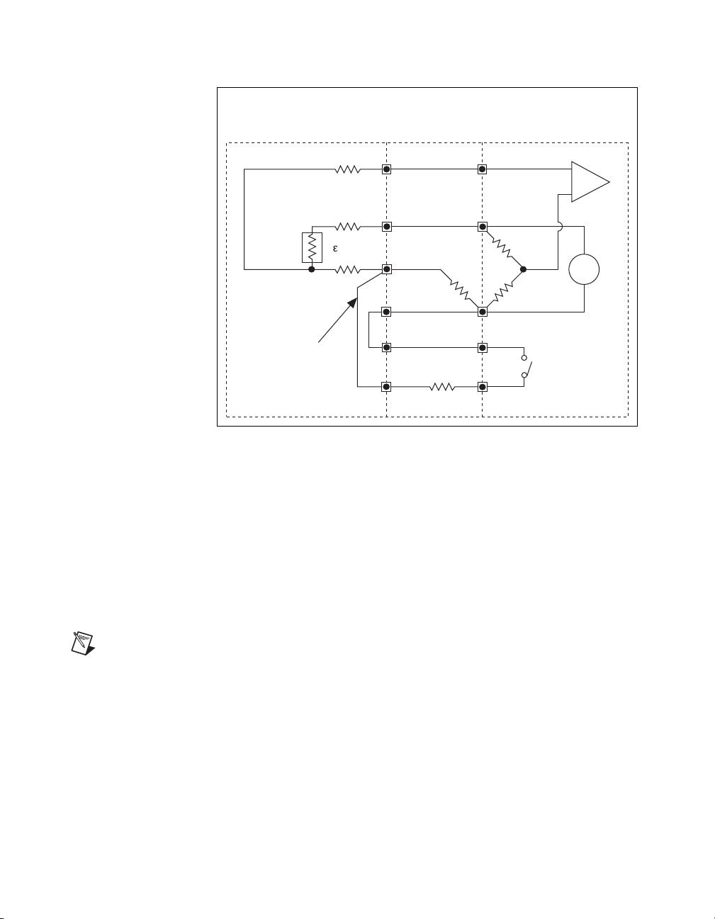
Half-Bridge Type I
Note S– is left unwired.
This section provides information for connecting the half-bridge
strain-gauge configuration type I. Figure 2-3 shows the half-bridge type I
circuit wiring diagram.
Figure 2-3. Half-Bridge Type I Circuit Diagram
The following symbols apply to the circuit diagram and equations:
•R
and R2 are half-bridge completion resistors.
1
•R
is the active element measuring compression from Poisson
3
effect (–νε).
Note As shown in Figure 2-4, for greatest calibration accuracy, use separate wires
•R
• V
• R
• V
between the bridge and the SCA terminals. Do not directly connect S+ or P– to the
SCXI-1520 User Manual 2-4 ni.com
SCA terminals inside the SCXI-1314 terminal block unless the strain-gauge cable
length is very short.
is the active element measuring tensile strain (+ε).
4
is the excitation voltage.
EX
is the lead resistance.
L
is the measured voltage.
CH
Page 24
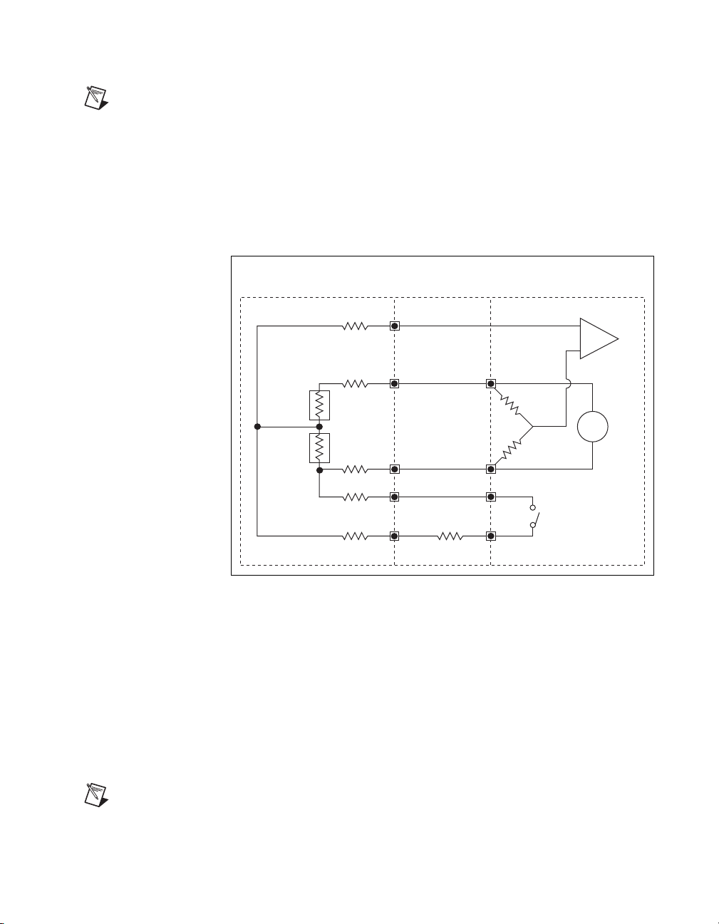
Half-Bridge Type II
+
–
+
–
S+
P+
P
R
L
R
L
R
L
SCA
SCA
Shunt
Cal A
+
–
SCXI-1314Transducer
V
CH
R
1
R
2
R
S
R
4
(gauge)
V
EX
R
3
(gauge)
R
L
R
L
V
out
+
V
out
SCXI-1520 Set Bridge
Configuration to Half Bridge
Note S– is left unwired.
Chapter 2 Connecting Signals
This section provides information for connecting the half-bridge
strain-gauge configuration type II. Figure 2-4 shows the half-bridge type II
circuit wiring diagram.
Figure 2-4. Half-Bridge Type II Circuit Diagram
The following symbols apply to the circuit diagram and equations:
•R
and R2 are half-bridge completion resistors.
1
•R
is the active element measuring compressive strain (–ε).
3
•R
© National Instruments Corporation 2-5 SCXI-1520 User Manual
Note As shown in Figure 2-3, for greatest calibration accuracy, use separate wires
between the bridge and the SCA terminals. Do not directly connect S+ or P– to the
SCA terminals inside the SCXI-1314 terminal block unless the strain-gauge cable
length is very short.
is the active element measuring tensile strain (+ε).
4
• V
• R
• V
is the excitation voltage.
EX
is the lead resistance.
L
is the measured voltage.
CH
Page 25
Chapter 2 Connecting Signals
+
–
V
EX
+
V
EX
+
–
S+
S
P+
P
R
1
R
2
R
4
R
3
SCA
SCA
Shunt
Cal A
+
–
+
–
R
L
R
L
SCXI-1520 Set Bridge
Configuration to Full BridgeSCXI-1314
Transducer
V
CH
R
S
CH+
CH
R
L
R
L
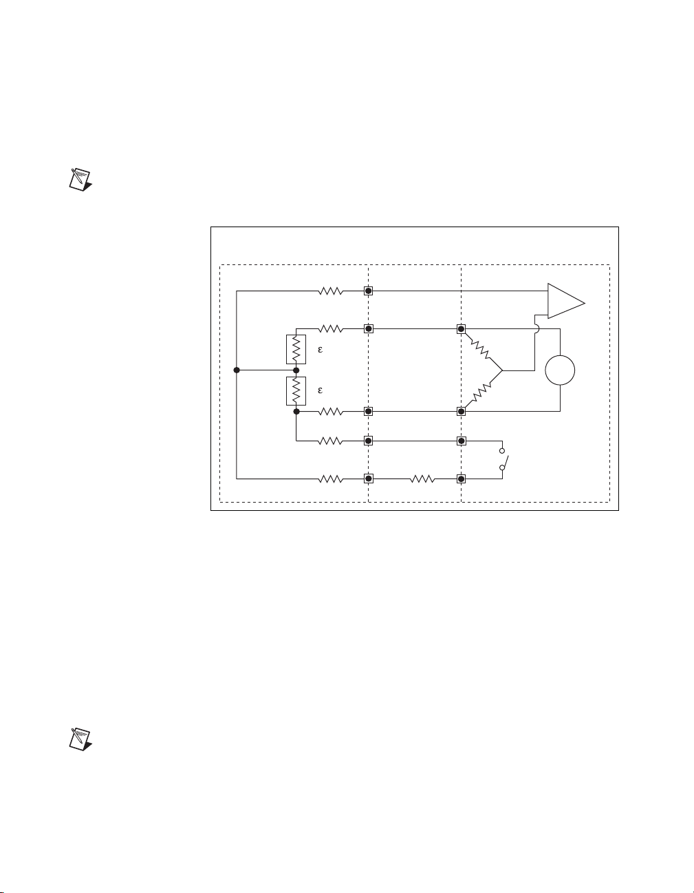
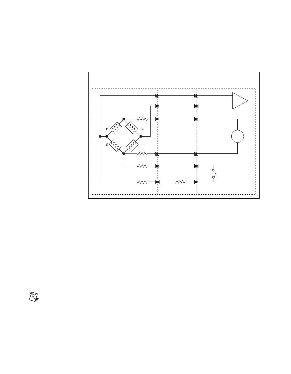
Full-Bridge Type I
This section provides information for connecting the full-bridge
strain-gauge configuration type I. Figure 2-5 shows the full-bridge type I
circuit wiring diagram.
Figure 2-5. Full-Bridge Type I Circuit Diagram
The following symbols apply to the circuit diagram and equations:
•R
is an active element measuring compressive strain (–ε).
1
•R
is an active element measuring tensile strain (+ε).
2
•R
is an active element measuring compressive strain (–ε).
3
•R
is an active element measuring tensile strain (+ε).
4
SCXI-1520 User Manual 2-6 ni.com
Note As shown in Figure 2-5, for greatest calibration accuracy, use separate wires
between the bridge and the SCA terminals. Do not directly connect S+ or P– to the
SCA terminals inside the SCXI-1314 terminal block unless the strain-gauge cable
length is very short.
• V
• R
• V
is the excitation voltage.
EX
is the lead resistance.
L
is the measured voltage.
CH
Page 26
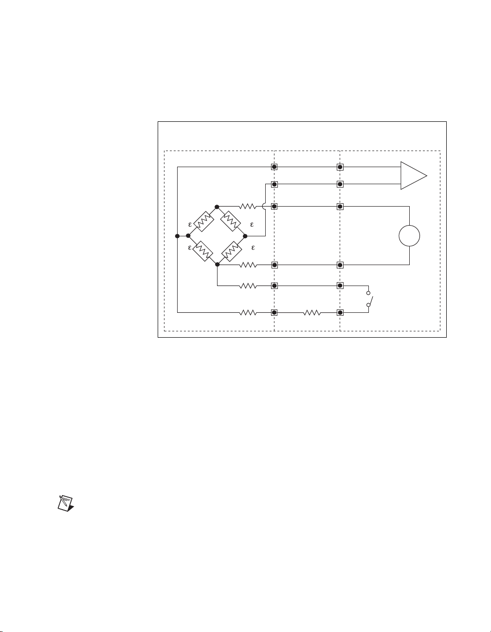
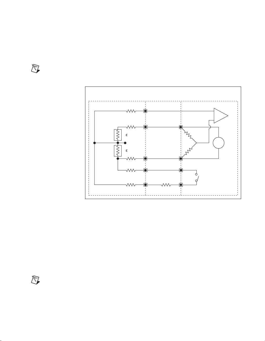
Full-Bridge Type II
+
–
+
–
S+
S
P+
P
SCA
SCA
Shunt
Cal A
+
–
–v
+v
R
L
R
L
SCXI-1520 Set Bridge
Configuration to Full BridgeSCXI-1314
Transducer
R
1
R
2
R
4
R
3
V
CH
R
S
V
EX
+
V
EX–
R
L
R
L
Chapter 2 Connecting Signals
This section provides information for connecting the full-bridge
strain-gauge configuration type II. Figure 2-6 shows the full-bridge type II
circuit wiring diagram.
Figure 2-6. Full-Bridge Type II Circuit Diagram
The following symbols apply to the circuit diagram and equations:
•R
is an active element measuring compressive Poisson effect (–νε).
1
•R
is an active element measuring tensile Poisson effect (+νε).
2
•R
is an active element measuring compressive strain (–ε).
3
© National Instruments Corporation 2-7 SCXI-1520 User Manual
Note As shown in Figure 2-6, for greatest calibration accuracy, use separate wires
between the bridge and the SCA terminals. Do not directly connect S+ or P– to the
SCA terminals inside the SCXI-1314 terminal block unless the strain-gauge cable
length is very short.
• V
• R
• V
•R
is an active element measuring tensile strain (+ε).
4
is the excitation voltage.
EX
is the lead resistance.
L
is the measured voltage.
CH
Page 27
Chapter 2 Connecting Signals
+
–
+
–
S+
S
P+
P
SCA
SCA
Shunt
Cal A
+
–v
–v
+
SCXI-1520 Set Bridge
Configuration to Full BridgeSCXI-1314
Transducer
R
1
R
2
R
4
R
3
V
CH
R
S
V
EX
+
V
EX–
R
L
R
L
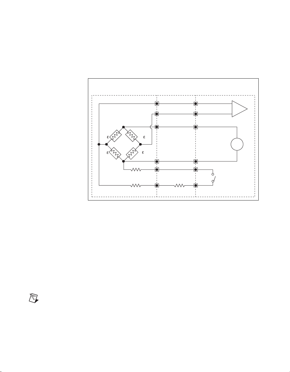
Full-Bridge Type III
This section provides information for connecting the full-bridge
strain-gauge configuration type I. The full-bridge type III only measures
axial strain. Figure 2-7 shows the full-bridge type III circuit wiring
diagram.
Figure 2-7. Full-Bridge Type III Circuit Diagram
The following symbols apply to the circuit diagram and equations:
•R
is an active element measuring compressive Poisson effect (–νε).
1
•R
is an active element measuring tensile strain (+ε).
2
•R
is an active element measuring compressive Poisson effect (–νε).
3
•R
is an active element measuring the tensile strain (+ε).
4
is the excitation voltage.
EX
is the lead resistance.
L
is the measured voltage.
CH
Note As shown in Figure 2-7, for greatest calibration accuracy, use separate wires
between the bridge and the SCA terminals. Do not directly connect S+ or P– to the
SCA terminals inside the SCXI-1314 terminal block unless the strain-gauge cable
• V
• R
• V
length is very short.
SCXI-1520 User Manual 2-8 ni.com
Page 28
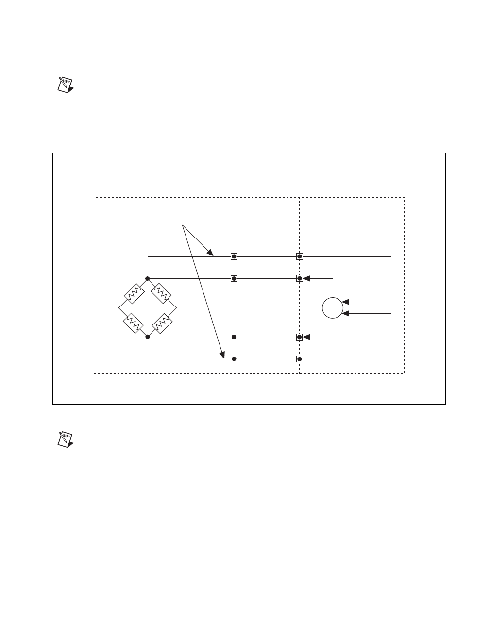
Remote Sense
Note NI recommends using remote sense if your application requires the improved
accuracy. Refer to Chapter 4, Theory of Operation, for more information about using
remote sense.
Run Separate Wires
Between Remote-Sense
Terminals and Bridge
R
1
Chapter 2 Connecting Signals
Wire the SCXI-1520 for remote sense as shown in Figure 2-8.
SCXI-1520SCXI-1314Transducer
RS+
V
EX
+
R
4
P+
+
–
Feedback
R
2
V
EX–
R
3
P
RS
Figure 2-8. Remote-Sense Circuit Diagram
Note
If you use remote sense, set RL to zero in the equations for measured strain (ε).
© National Instruments Corporation 2-9 SCXI-1520 User Manual
Page 29

Chapter 2 Connecting Signals
Pin Assignments
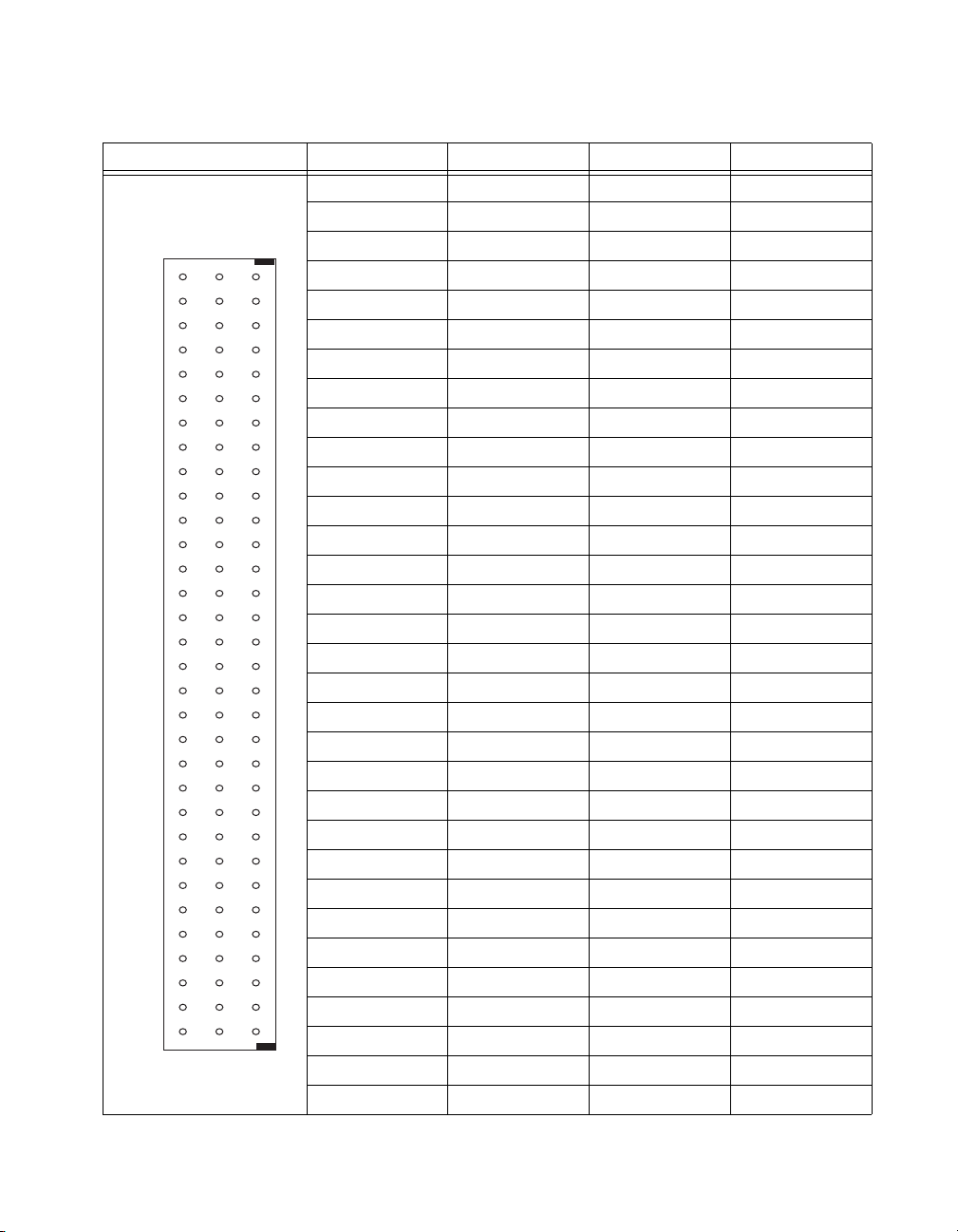
The pin assignments for the SCXI-1520 front signal connector are shown
in Table 2-1. The front signal connector is a special 96-pin DIN C male
connector through which you make all signal connections. The terminal
assignments are as follows:
•SX+ and SX– are for analog input
•RSX+ and RSX– are for remote sense
•PX+ and PX– are for excitation output
•SCAX are for shunt calibration circuit A
•SCBX are for shunt calibration circuit B
where X is the channel number.
The negative terminals are listed in Column B and the positive terminals are
listed in Column C. The pins labeled RSVD are reserved. Do not make any
connections to the RSVD pins.
SCXI-1520 User Manual 2-10 ni.com
Page 30
Column
A B C
32
31
30
29
28
27
26
25
24
23
22
21
20
19
18
17
16
15
14
13
12
11
10
9
8
7
6
5
4
3
2
1
© National Instruments Corporation 2-11 SCXI-1520 User Manual
Chapter 2 Connecting Signals
Table 2-1. Front Signal Pin Assignments
Front Connector Diagram Pin Number Column A Column B Column C
32 SCB0 S0– S0+
31 SCB0 RS0– RS0+
30 SCB1 P0– P0+
29 SCB1 SCA0 SCA0
28 RSVD S1– S1+
27 RSVD RS1– RS1+
26 RSVD P1– P1+
25 RSVD SCA1 SCA1
24 SCB2 S2– S2+
23 SCB2 RS2– RS2+
22 SCB3 P2– P2+
21 SCB3 SCA2 SCA2
20 RSVD S3– S3+
19 RSVD RS3– RS3+
18 RSVD P3– P3+
17 RSVD SCA3 SCA3
16 SCB4 S4– S4+
15 SCB4 RS4– RS4+
14 SCB5 P4– P4+
13 SCB5 SCA4 SCA4
12 RSVD S5– S5+
11 RSVD RS5– RS5+
10 RSVD P5– P5+
9 RSVD SCA5 SCA5
8 SCB6 S6– S6+
7 SCB6 RS6– RS6+
6 SCB7 P6– P6+
5 SCB7 SCA6 SCA6
4 RSVD S7– S7+
3 RSVD RS7– RS7+
2 RSVD P7– P7+
1 RSVD SCA7 SCA7
Page 31

Chapter 2 Connecting Signals
The rear signal connector is a 50-pin male cable connector used for analog
signal connectivity and communication between the SCXI-1520 and the
connected E/M Series DAQ device. The rear signal connector is shown in
Table 2-2. The rear signal connector allows the DAQ device to access all
eight differential analog output signals from the SCXI-1520. The positive
terminal of each analog output is named CHX+ and the negative terminal
CHX–.
SCXI-1520 User Manual 2-12 ni.com
Page 32

Rear Connector
Diagram
12
3 4
56
7 8
910
11 12
13 14
15 16
17 18
19 20
21 22
23 24
25 26
27 28
29 30
31 32
33 34
35 36
37 38
3940
41 42
43 44
45 46
47 48
49 50
Chapter 2 Connecting Signals
Table 2-2. Rear Signal Pin Assignments
Signal Name Pin Number Pin Number Signal Name
— 1 2 —
CH 0 + 3 4 CH 0 –
CH 1 + 5 6 CH 1 –
CH 2 + 7 8 CH 2 –
CH 3 + 9 10 CH 3 –
CH 4 + 11 12 CH 4 –
CH 5 + 13 14 CH 5 –
CH 6 + 15 16 CH 6 –
CH 7 + 17 18 CH 7 –
— 19 20 —
— 21 22 —
— 23 24 DIG GND
SER DAT IN 25 26 SER DAT OUT
DAQ D*/A 27 28 —
SLOT 0 SEL* 29 30 —
— 31 32 —
DIG GND 33 34 —
— 35 36 AI HOLD COMP, AI HOLD
SER CLK 37 38 —
— 39 40 —
— 41 42 —
— 43 44 —
— 45 46 SYNC
— 47 48 —
— 49 50 —
In parallel output mode, channel 0 is selected at the output multiplexer and
is connected to CH 0. The seven other channels are directly connected to
CH 1 through CH 7, respectively, on the rear connector.
© National Instruments Corporation 2-13 SCXI-1520 User Manual
Page 33

Chapter 2 Connecting Signals
In multiplexed mode, the CH 0 signal pair is used for sending all eight
channels of the SCXI-1520, and analog signals from other modules, to the
connected E/M Series DAQ device. If the module is cabled directly to the
DAQ device, the other analog channels of the DAQ device are unavailable
for general-purpose analog input because they are connected to the
SCXI-1520 amplifier outputs. This means that connecting an SCXI-1180
module to the 50-pin breakout connector of the SCXI-1349, or other cable
adapter assembly, may cause interference and incorrect measurements
when the DAQ device is cabled to the SCXI-1520.
The communication signals between the DAQ device and the SCXI system
are listed in Table 2-3. If the DAQ device is connected to the SCXI-1520,
these digital lines are unavailable for general-purpose digital I/O.
Table 2-3. SCXI-1520 Communication Signals
NI-DAQmx
SCXI
Pin
24, 33 DIG GND D GND DGND — Digital ground—these
25 SER DAT IN P0.0 DIO0 Input Serial data in—this
26 SER DAT OUT P0.4 DIO4 Output Serial data out—this
27 DAQ D*/A P0.1 DIO1 Input Board data/address
Signal Name
Device Signal
Name
Traditional NI-DAQ
(Legacy) Device
Signal Name
Direction Description
pins supply the
reference for
E/M Series DAQ device
digital signals and are
connected to the
module digital ground.
signal taps into the
SCXIbus MOSI line to
send serial input data to
a module or Slot 0.
signal taps into the
SCXIbus MISO line to
accept serial output data
from a module.
line—this signal taps
into the SCXIbus D*/A
line to indicate to the
module whether the
incoming serial stream
is data or address
information.
SCXI-1520 User Manual 2-14 ni.com
Page 34

Chapter 2 Connecting Signals
Table 2-3. SCXI-1520 Communication Signals (Continued)
NI-DAQmx
SCXI
Pin
29 SLOT0SEL* P0.2 DIO2 Input Slot 0 select—this
36 SCANCLK AI HOLD COMP,
37 SER CLK EXTSTROBE* EXTSTROBE* Input Serial clock—this
46 HOLD TRIG PFI 7/
Signal Name
Device Signal
Name
AI HOLD
AI SAMP CLK,
AI SAMP
Traditional NI-DAQ
(Legacy) Device
Signal Name
SCANCLK Input Scan clock—a rising
PFI7/
START SCAN
Direction Description
signal taps into the
SCXIbus INTR* line to
indicate whether the
information on MOSI is
being sent to a module
or Slot 0.
edge indicates to the
scanned SCXI module
that the E/M Series
DAQ device has taken a
sample and causes the
module to advance
channels.
signal taps into the
SCXIbus SPICLK line
to clock the data on the
MOSI and MISO lines.
Input Hold trigger—this
signal is used by the
MIO to set the
track-and-hold state of
the module.
© National Instruments Corporation 2-15 SCXI-1520 User Manual
Page 35

Configuring and Testing
This chapter discusses configuring the SCXI-1520 in MAX for use with
either NI-DAQmx or Traditional NI-DAQ (Legacy), creating and testing a
virtual channel, global channel, and/or task.
SCXI-1520 Software-Configurable Settings
This section describes how to set the bridge configuration, voltage
excitation level, filter bandwidth, and gain/input signal range, as well as
how to use configuration utilities in MAX to programmatically perform
offset null compensation and shunt calibration. It also describes how to
perform configuration of these settings for the SCXI-1520 in NI-DAQmx
and Traditional NI-DAQ (Legacy). For more information on the
relationship between the settings and the measurements, and how to
configure settings in your application, refer to Chapter 4, Theory of
Operation.
Common Software-Configurable Settings
This section describes the most frequently used software-configurable
settings for the SCXI-1520. Refer to Chapter 4, Theory of Operation,
for a complete list of software-configurable settings.
3
Bridge Configuration
Bridge configuration is a software-configurable setting that allows you to
connect quarter-, half-, or full-bridge configuration Wheatstone bridge
sensors easily. When quarter- or half-bridge configuration is selected,
Terminal SX– (where X is a particular channel) is disconnected from the
front signal connector and internally connected to a half-bridge completion
network. Implementing quarter-bridge completion also involves making
field wiring connections to the quarter-bridge completion resistor (QTR) in
the terminal block.
© National Instruments Corporation 3-1 SCXI-1520 User Manual
Page 36

Chapter 3 Configuring and Testing
Excitation Level
Excitation level is a software-configurable setting that allows you to set the
voltage excitation level available on PX+ and PX– (where X is a particular
channel). You can choose voltage excitation settings between 0 and 10 V.
To prevent the module from overheating, do not set the excitation voltage
greater than
Note You need not include the loading effect of the internal half-bridge completion
resistors in the above calculation. When using internal quarter-bridge completion you must
include the nominal gauge resistance as well as the quarter-bridge completion resistance
+ R4).
(R
3
Table 3-1 shows the maximum allowable excitation voltages for standard
bridge configurations and resistances.
Table 3-1. Excitation Voltage for Configuration and Gauge Resistances
Configuration/
Sensor
Resistance
(resistance connected between the excitation terminals) × (29.0 mA)
Traditional NI-DAQ
NI-DAQmx Excitation
Vol ta g e R an g e
(Legacy) Excitation
Voltage Range
Quarter- or
Half-Bridge
120 Ω ≤6.96 V 0 to 6.875 V
350 Ω 0 to 10 V 0 to 10 V
1000 Ω 0 to 10 V 0 to 10 V
Full-Bridge or
Full-Bridge Sensor
120 Ω ≤3.48 V 0 to 3.125 V
350 Ω 0 to 10 V 0 to 10 V
1000 Ω 0 to 10 V 0 to 10 V
Filter Bandwidth
Filter bandwidth is a software-configurable setting that allows you to select
a lowpass filter cutoff frequency. You can choose 10 Hz, 100 Hz, 1 kHz,
10 kHz, or filter-bypass mode. If your application requires other cutoff
frequencies, refer to Chapter 4, Theory of Operation.
SCXI-1520 User Manual 3-2 ni.com
Page 37

Chapter 3 Configuring and Testing
quarter bridge (max strain) (excitation voltage)× (0.5 ×μV/V/με)=
half bridge (max strain) (excitation voltage)× (1.0 ×μV/V/με)=
full bridge (max strain) (excitation voltage)× (2.0 ×μV/V/με)=
gain
SCXI-1520 output voltage range()10 V()×
input signal voltage()
----------------------------------------------------------------------------------------------------------
≤
(max input signal voltage)
(sensor sensitivity) (excitation voltage)× (maximum input)×
(sensor full-scale input)
-------------------------------------------------------------------------------------------------------------------------------------------------=
12 mV
3.0 mV/V()10 V()200 psi()××
500 psi()
--------------------------------------------------------------------------------=
Gain/Input Range
Gain/input range is a software-configurable setting that allows you to
choose the appropriate amplification to fully utilize the range of the
E/M Series DAQ device. In most applications NI-DAQ chooses and sets
the gain for you determined by the input range. This feature is described in
Chapter 4, Theory of Operation. Otherwise, you should determine the
appropriate gain using the input signal voltage range and the full-scale
limits of the SCXI-1520 output signal. For common strain-gauge
configurations where the Gauge Factor is 2.0, the maximum input signal
(in microvolts) is:
When you have determined the input signal voltage you can use the
following equation to determine the appropriate gain:
© National Instruments Corporation 3-3 SCXI-1520 User Manual
If you are using a bridge-based sensor, use the manufacturer-specified
sensitivity (usually expressed in the units of millivolts per volt) to
determine the maximum input signal. The maximum input signal is:
For example, if you have a 0 to 500 psi pressure sensor with 3.0 mV/V
sensitivity, an excitation voltage of 10 V, and a maximum pressure of
200 psi, the maximum signal is:
Page 38

Chapter 3 Configuring and Testing
833
10 V
12 mV
----------------=
If you are using a DAQ device that has a maximum analog input range of
±10 V and you have a maximum input to the SCXI-1520 of +12 mV, set the
gain to the setting closest to
but less than 833. A larger gain setting saturates the DAQ device input for
a 12 mV signal. In this example, the closest lesser gain setting for the
SCXI-1520 is 750.
Null Potentiometers
Coarse and fine null potentiometers are software-configurable settings that
allow you to remove unwanted offset voltage. In most cases, you do not
explicitly set the null potentiometers, but instead allow driver software to
automatically adjust them for you. However, if you want to explicitly set
the null potentiometers, you can write an application program that adjusts
the null potentiometers settings. Refer to Chapter 4, Theory of Operation,
for more information.
Shunt Calibration Switches
Shunt calibration switches A and B are software control settings that allow
you to engage or disengage the shunt calibration resistors in order to
perform gain calibration. In most cases, you do not explicitly control
the shunt calibration switches, but instead allow driver software to
automatically adjust them for you during the automated shunt calibration
procedure. However, if you want to explicitly control the calibration
switches, you can write an application program that controls the shunt
calibration switches. Refer to Chapter 4, Theory of Operation, for more
information.
Note The gain adjustment is done for you automatically if you have performed shunt
calibration using the NI-DAQ driver. Refer to the Traditional NI-DAQ (Legacy) section
and the NI-DAQmx section for more information about how to perform shunt calibration
using the driver.
SCXI-1520 User Manual 3-4 ni.com
Page 39

Chapter 3 Configuring and Testing
Modes of Operation
The SCXI-1520 can operate in multiplexed mode or parallel mode. Using
NI-DAQmx, you can operate the SCXI-1520 in either multiplexed or
parallel mode. In Traditional NI-DAQ (Legacy), only multiplexed mode is
supported. Refer to the Strain-Gauge Theory section of Chapter 4, Theory
of Operation, for more information on multiplexed and parallel mode
operation.
Simultaneous Sample and Hold
When it is critical to measure two or more signals at the same instant
in time, simultaneous sample and hold (SS/H) is required. Typical
applications that might require SS/H include vibration measurements
and phase difference measurements. In NI-DAQmx, you can disable this
setting through your application if you require scan rates beyond the
maximum allowable with SS/H engaged. NI recommends leaving SS/H
engaged.
Note You cannot change the simultaneous sampling mode in MAX. You must use an ADE
such as LabVIEW or LabWindows/CVI to configure the setting using NI-DAQmx Channel
Property Node. Refer to your ADE help file for more information.
Configurable Settings in MAX
Note If you are not using an NI ADE, using an NI ADE prior to version 7.0, or are using
an unlicensed copy of an NI ADE, additional dialog boxes from the NI License Manager
appear allowing you to create a task or global channel in unlicensed mode. These messages
continue to appear until you install version 7.0 or later of an NI ADE.
This section describes where you can access each software-configurable
setting for modification in MAX. The location of the settings varies
depending on the version of NI-DAQ you use. Refer to either the
NI-DAQmx section or the Traditional NI-DAQ (Legacy) section. You also
can refer to the DAQ Getting Started Guide and the SCXI Quick Start Guide
for more information on installing and configuring the hardware. You also
can use the DAQ Assistant to graphically configure common measurement
tasks, channels, or scales.
© National Instruments Corporation 3-5 SCXI-1520 User Manual
Page 40

Chapter 3 Configuring and Testing
NI-DAQmx
In NI-DAQmx, you can configure software settings such as bridge
configuration, voltage excitation level, filter bandwidth, gain/input signal
range, and calibration settings in the following two ways:
• Task or global channel in MAX
• Functions in your application
Note All software-configurable settings are not configurable both ways. This section only
discusses settings in MAX. Refer to Chapter 4, Theory of Operation, for information on
using functions in your application.
These sections describe settings that you can change in MAX and where
they are located. Strain and custom voltage with excitation are the most
commonly used NI-DAQmx Task or NI-DAQmx Global Channel types
with the SCXI-1520. Use the Custom Voltage with Excitation
NI-DAQmx task or global channel when measuring load, force, torque,
pressure, or other bridge-based sensors:
• Bridge configuration—configure using the settings tab of NI-DAQmx
• Voltage excitation—configure using either NI-DAQmx Task or
• Filter bandwidth—configure the Device tab using either NI-DAQmx
• Input signal range—configure the input signal range using either
• Calibration settings—null potentiometer settings and control shunt
Task or NI-DAQmx Global Channel and functions in your
application. Channel properties override module properties.
The default bridge configuration for NI-DAQmx is full bridge.
NI-DAQmx Global Channel. You also can set the voltage excitation
level through your application. In NI-DAQmx, you can choose from
contiguous voltages between 0 and 10 V. The default voltage
excitation in NI-DAQmx is 0 V.
Task or NI-DAQmx Global Channel. You also can set the value
through your application. The default filter cut-off frequency in
NI-DAQmx is 10 kHz.
NI-DAQmx Task or NI-DAQmx Global Channel. When you set the
minimum and maximum range of NI-DAQmx Task or NI-DAQmx
Global Channel, the driver selects the best gain for the measurement.
You also can set it through your application. The default gain setting in
NI-DAQmx is 1.0. This setting corresponds to an input range of ±10 V.
calibration switches only using Strain NI-DAQmx Task, Strain
NI-DAQmx Global Channel, or your application. The Custom
Voltage with Excitation NI-DAQmx Task or NI-DAQmx Global
Channel cannot adjust calibration settings in MAX. Adjust calibration
SCXI-1520 User Manual 3-6 ni.com
Page 41

Chapter 3 Configuring and Testing
settings in your application. The default configuration settings set the
null potentiometers at their midpoint, 62 for the coarse potentiometer
and 2,047 for the fine potentiometer. The default state of the shunt
calibration switches is open. This state leaves the shunt calibration
resistor disconnected from the circuit.
• Modes of operation—configure only using chassis installation in
software. Refer to Chapter 1, About the SCXI-1520, for more
information on chassis installation. The default setting in NI-DAQmx
is multiplexed.
• Simultaneous sample-and-hold settings—configure only using your
application. The default setting in NI-DAQmx engages SS/H.
Note Refer to Chapter 4, Theory of Operation, for information on configuring the settings
for your application using Traditional NI-DAQ (Legacy).
Creating a Strain Global Channel or Task
To create a new NI-DAQmx strain global task or channel, complete the
following steps:
1. Double-click Measurement & Automation on the desktop.
2. Right-click Data Neighborhood and select Create New.
3. Select NI-DAQmx Task or NI-DAQmx Global Channel, and
click Next.
4. Select Analog Input.
5. Select Strain.
6. If you are creating a task, you can select a range of channels by holding
down the <Shift> key while selecting the channels. You can select
multiple individual channels by holding down the <Ctrl> key while
selecting channels. If you are creating a channel, you can only select
one channel. Click Next.
7. Name the task or channel and click Finish.
8. In the Channel List box, select the channel(s) you want to configure.
You can select a range of channels by holding down the <Shift> key
while selecting the channels. You can select multiple individual
channels by holding down the <Ctrl> key while selecting channels.
9. Enter the specific values for your application in the Settings tab.
Context help information for each setting is provided on the right side
of the screen.
10. Click the Device tab and select the autozero mode and lowpass filter
cutoff frequency.
© National Instruments Corporation 3-7 SCXI-1520 User Manual
Page 42

Chapter 3 Configuring and Testing
11. Ensure that you have selected the strain channel(s) you wish to
12. On the screen that appears choose to enable offset nulling and/or
13. Measure and Calibrate displays information specific to the strain
14. If you are creating a task and want to set timing or triggering controls,
Creating a Custom Voltage with Excitation Global Channel or Task
Use the Custom Voltage with Excitation NI-DAQmx Task or Global
Channel when measuring load, force, torque, pressure, or other
bridge-based sensors. To create an NI-DAQmx Custom Voltage
with Excitation Task or NI-DAQmx Global Channel, complete the
following steps:
1. Double-click Measurement & Automation on the desktop.
2. Right-click Data Neighborhood and select Create New.
3. Select NI-DAQmx Global Channel or NI-DAQmx Task, and
4. Select Analog Input then select Custom Voltage with Excitation.
5. If you are creating a channel, you can select only one channel. If you
6. Select the name of the task or channel, and click Finish.
7. In the Channel List box, select the channel(s) you want to configure.
8. Enter the specific values for your application in the Settings tab.
calibrate in the Channel List box. Click Calibration to calibrate the
strain channel(s).
shunt calibration. Enter the shunt calibration resistor information.
Click Next.
channel(s). Click Measure to acquire a signal from the strain
channel(s) and Reset Data to reset the values to default. Click
Calibrate to calibrate the strain channel(s). When you have completed
calibrating the strain channel(s), click Finish.
enter the values in the Task Timing and Task Triggering tabs.
click Next.
are creating a task, select the channels to add to the task. You can select
a range of channels by holding down the <Shift> key while selecting
the channels. You can select multiple individual channels by holding
down the <Ctrl> key while selecting channels. Click Next.
You can select a range of channels by holding down the <Shift> key
while selecting the channels. You can select multiple individual
channels by holding down the <Ctrl> key while selecting channels.
Context help information for each setting is provided on the right side
of the screen.
SCXI-1520 User Manual 3-8 ni.com
Page 43

9. Click the Device tab and select the autozero mode and lowpass filter
cutoff frequency.
10. If you are applying custom scaling, select the Create New drop-down
and follow the onscreen wizard.
11. If you are creating a task and want to set timing or triggering controls,
enter the values in the Task Timing and Task Triggering tabs.
Traditional NI-DAQ (Legacy)
In Traditional NI-DAQ (Legacy), you can configure software settings,
such as bridge configuration, voltage excitation level, filter bandwidth,
gain/input signal range, and calibration settings, in the following
three ways:
• module property pages in MAX
• virtual channels properties in MAX
• functions in your ADE
Note All software-configurable settings are not configurable in all three ways. This
section only discusses settings in MAX. Refer to Chapter 4, Theory of Operation, for
information on using functions in your application.
Chapter 3 Configuring and Testing
Most of these settings are available in module properties and/or using
virtual channels:
• Bridge configuration—configure using module properties, virtual
channels properties, and functions in your application. Virtual
channel properties override module properties. The default bridge
configuration for Traditional NI-DAQ (Legacy) is quarter bridge.
• Voltage excitation—configure using module properties or virtual
channel properties. Virtual channel properties override module
properties settings. You also can set excitation through your
application. You can choose one of 17 voltage settings between
0 and 10 V. The default voltage excitation level for Traditional
NI-DAQ (Legacy) is 2.5 V.
• Filter bandwidth—configure only using module properties. You also
can set bandwidth through your application. The default filter
bandwidth level for Traditional NI-DAQ (Legacy) is 10 Hz.
• Gain/input signal range—configure gain using module properties.
When you set the minimum and maximum range of the virtual
channel, the driver selects the best gain. The default gain setting
for Traditional NI-DAQ (Legacy) is 100.
© National Instruments Corporation 3-9 SCXI-1520 User Manual
Page 44

Chapter 3 Configuring and Testing
• Calibration settings—configure null potentiometer settings and
• Modes of operation—configure only using module properties. The
• Simultaneous sample-and-hold settings—can modify this setting only
Note Refer to Chapter 4, Theory of Operation, for information on configuring the settings
for your application using Traditional NI-DAQ (Legacy).
Configuring Module Property Pages in Traditional NI-DAQ (Legacy)
1. Right-click the SCXI-1520 module you want to configure and select
2. If the module you are configuring is connected to an E Series DAQ
3. Click the Channel tab. Select the appropriate gain, filter, voltage
4. Click Accessory. Select the accessory you connected to the module.
control shunt calibration switches only using strain virtual channel or
using your application. The default configuration settings set the null
potentiometers at their midpoint, 62 for the coarse potentiometer
and 2,047 for the fine potentiometer. The default state of the shunt
calibration switches is open. This state leaves the shunt calibration
resistor disconnected from the circuit.
default setting in Traditional NI-DAQ (Legacy) is multiplexed mode.
Parallel mode is not supported in Traditional NI-DAQ (Legacy).
using NI-DAQmx.
Properties. Click General.
device, select that device by using Connected to. If you want this DAQ
device to control the chassis, confirm there is a check in the This
device will control the chassis checkbox. If the module you are
configuring is not connected to an DAQ device, select None.
excitation, and bridge configuration setting for each channel. If you
want to configure all the channels at the same time, select the Channel
drop-down menu, scroll to the bottom, and select All Channels. Refer
to the SCXI-1520 Software-Configurable Settings section for a
detailed description of each setting. Click Apply.
When configuration is complete, click OK.
The Traditional NI-DAQ (Legacy) chassis and SCXI-1520 should now
be configured properly. If you need to change the module configuration,
right-click the module and repeat steps 1 through 4. Test the system
following the steps in the Troubleshooting the Self-Test Verification
section of Chapter 1, About the SCXI-1520.
SCXI-1520 User Manual 3-10 ni.com
Page 45

Chapter 3 Configuring and Testing
Creating a Strain Virtual Channel
To create a strain virtual channel, complete the following steps:
1. Right-click Data Neighborhood and select Create New.
2. Select Traditional NI-DAQ Virtual Channel and click Finish.
3. Click Add Channel.
4. Select Analog Input from the drop-down menu and click Next.
5. Enter the Channel Name and Channel Description, and click Next.
6. Select Strain Gauge from the drop-down menu and click Next.
7. Enter the following information:
a. Bridge type from the drop-down menu
b. V init in volts
c. Lead Resistance in Ω
d. Nominal Gauge in Ω
e. Gauge Factor
f. Range min in με
g. Range max in με
8. Click Next.
9. Enter the following information:
a. What DAQ hardware will be used? from the drop-down menu
b. What channel on your DAQ hardware? from the drop-down
menu
c. Which analog input mode will be used? from the drop-down
menu
d. What is the Excitation Voltage’s source and value? from the
drop-down menu
e. Voltage in volts
10. Click Finish.
Calibrating a Strain Virtual Channel
To calibrate a strain virtual channel, complete the following steps:
1. Right-click the virtual channel you want to calibrate and select
Properties.
2. Click Calibration.
3. Select the Engineering Units from the drop-down menu.
© National Instruments Corporation 3-11 SCXI-1520 User Manual
Page 46

Chapter 3 Configuring and Testing
4. Enter the Calibration Data and click Update.
5. Make the selections in Shunt Cal Circuit A and Operation, and
click Start.
6. After the calibration is completed, click Exit.
Verifying the Signal
This section describes how to take measurements using test panels in order
to verify signal, and configuring and installing a system in NI-DAQmx and
Traditional NI-DAQ (Legacy).
Verifying the Signal in NI-DAQmx Using a Task or Global Channel
You can verify the signals on the SCXI-1520 using NI-DAQmx by
completing the following steps:
1. Expand the list of tasks and virtual channels by clicking the + next to
Data Neighborhood.
2. Click the + next to NI-DAQmx Tasks to expand the list of tasks.
3. Click the task.
4. Add or remove channels, if applicable, in the Channel List. Click the
Add Channels button, shown at left, and select the type of channel you
want to add.
a. In the window that appears, expand the list of channels by clicking
the + next to the module of interest.
b. Select the channel(s) you want to verify. You can select a block of
channels by holding down the <Shift> key or multiple channels by
holding down the <Ctrl> key. Click OK.
5. Enter the appropriate information on the Settings tab.
6. Click the Device tab and enter the appropriate information on the
Device tab.
7. Click the Test button to open the test panel.
8. Click the Start button, if necessary.
9. After you have completed verifying the channels, close the test panel
window.
You have now verified the SCXI-1520 configuration and signal connection.
SCXI-1520 User Manual 3-12 ni.com
Page 47

Note For more information on how to further configure the SCXI-1520, or how to use
LabVIEW to configure the module and take measurements, refer to Chapter 4, Theory of
Operation.
Verifying the Signal in Traditional NI-DAQ (Legacy)
This section discusses how to verify the signal in Traditional NI-DAQ
(Legacy) using channel strings and virtual channels.
Verifying the Signal Using Channel Strings
The format of the channel string is as follows:
obx
! scy ! mdz ! channel
where
obx is the onboard E Series DAQ device channel, with x representing
a particular channel where the multiplexed channels are sent. This
value is 0 for DAQ device channel 0 in a single-chassis system. In a
multichassis or remote chassis system, the DAQ device channel x
corresponds to chassis number n – 1, where DAQ device channel x is
used for scanning the nth chassis in the system.
scy is the SCXI chassis ID, where y is the number you chose when
configuring the chassis.
mdz is the slot position where the module is located, with z being the
particular slot number. The slots in a chassis are numbered from left to
right, starting with 1.
channel is the channel that is sampled from module z.
Chapter 3 Configuring and Testing
Use the format
single input channel.
Complete the following steps to use channel strings in verifying the signal:
1. Expand the list of tasks and virtual channels by clicking the + next to
Devices and Interfaces.
2. Click the + next to Traditional NI-DAQ Devices to expand the
device list.
3. Right-click the appropriate E Series DAQ device.
4. Click Test Panels.
5. Enter the channel string.
6. Enter the input limits.
© National Instruments Corporation 3-13 SCXI-1520 User Manual
obx ! scy ! mdz ! n to verify the signal, where n is a
Page 48

Chapter 3 Configuring and Testing
7. Select the Data Mode.
8. Select the Y Scale Mode.
Refer to the LabVIEW Measurements Manual for more information and for
proper formatting of channel strings for different uses.
Verifying the Signal Using Strain Virtual Channel
If you have already created a virtual channel, complete the following steps
to verify the signal:
1. Right-click the strain virtual channel you want to verify and
select Test.
2. In Channel Names, select the channel you want to verify.
3. When you have completed verifying the channel, click Close.
Using the Strain Calibration Wizard in NI-DAQmx
When using NI-DAQmx, you can perform an automated strain calibration
on one or more channels in your task using the Strain Calibration Wizard
in MAX.
Note All channels must be strain channels to use the Strain Calibration Wizard.
Complete the following steps to perform calibration using the Calibration
Wizard:
1. Expand the list of devices by clicking the + next to Data
Neighborhood.
2. Click the + next to NI-DAQmx Tasks to expand the list of tasks.
3. Select the strain task you previously created.
4. Click the Device tab.
5. Select the Auto Zero Mode and Lowpass Filter Cutoff Frequency
from the dropdown lists.
6. Click the Calibration button and follow the onscreen instructions.
SCXI-1520 User Manual 3-14 ni.com
Page 49

Theory of Operation
This chapter discusses strain-gauge concepts and the theory of operational
measurement concepts.
Strain-Gauge Theory
This section discusses how to arrange, connect, and scale signals from
bridge-based sensors, especially strain gauges.
Wheatstone Bridges
All strain-gauge configurations are based on the concept of a Wheatstone
bridge. A Wheatstone bridge is a network of four resistive legs. One or
more of these legs can be active sensing elements. Figure 4-1 shows a
Wheatstone bridge circuit diagram.
4
V
+
EX
R
1
–
R
2
Figure 4-1. Basic Wheatstone Bridge Circuit Diagram
The Wheatstone bridge is the electrical equivalent of two parallel voltage
divider circuits. R
compose the second voltage divider circuit. The output of a Wheatstone
R
3
bridge is measured between the middle nodes of the two voltage dividers.
© National Instruments Corporation 4-1 SCXI-1520 User Manual
and R2 compose one voltage divider circuit, and R4 and
1
R
4
+
V
CH
R
3
Page 50

Chapter 4 Theory of Operation
Strain Gauges
A physical phenomena, such as a change in strain or temperature applied
to a specimen, changes the resistance of the sensing elements in the
Wheatstone bridge. The Wheatstone bridge configuration is used to help
measure the small variations in resistance that the sensing elements
produce corresponding to a physical changes in the specimen.
Strain-gauge configurations are arranged as Wheatstone bridges. The
gauge is the collection of all of the active elements of the Wheatstone
bridge. There are three types of strain-gauge configurations: quarter-, half-,
and full-bridge. The number of active element legs in the Wheatstone
bridge determines the kind of bridge configuration. Table 4-1 shows the
number of active elements in each configuration.
Table 4-1. Strain-Gauge Configurations
Configuration Number of Active Elements
Quarter-bridge 1
Half-bridge 2
Full-bridge 4
Each of these configurations is subdivided into multiple configuration
types. The orientation of the active elements and the kind of strain
measured determines the configuration type. NI supports seven
configuration types in software. However, with custom software scaling
you can use all Wheatstone bridge configuration types with any
NI hardware product that supports the gauge configuration type.
The supported strain-gauge configuration types measure axial strain,
bending strain, or both. While you can use some similar configuration types
to measure torsional strain, NI software scaling does not support these
configuration types. It is possible to use NI products to measure torsional
strain, but to properly scale these configuration types you must create a
custom scale in MAX or perform scaling in your software application.
This document discusses all of the mechanical, electrical, and scaling
considerations of each strain-gauge configuration type supported by NI.
SCXI-1520 User Manual 4-2 ni.com
Page 51

Acronyms, Formulas, and Variable Definitions
U
R
g
–
4R
s
2Rg+
------------------------=
V
r
VCHstrained()VCH(unstrained)–
V
EX
-------------------------------------------------------------------------------
=
In the figures and equations in this document, the acronyms, formulas, and
variables are defined as follows:
ε is the measured strain (+ε is tensile strain and –ε is compressive strain).
is the simulated strain.
ε
S
GF is the Gauge Factor, which should be specified by the gauge
manufacturer.
is the nominal gauge resistance, which should be specified by the gauge
R
g
manufacturer.
is the lead resistance. If lead lengths are long, RL can significantly
R
L
impact measurement accuracy.
is the shunt calibration resistor value.
R
s
U is the ratio of expected signal voltage to excitation voltage with the shunt
calibration circuit engaged. Parameter U appears in the equations for
simulated strain and is defined by the following equation:
Chapter 4 Theory of Operation
ν is the Poisson’s ratio, defined as the negative ratio of transverse strain to
axial strain (longitudinal) strain. Poisson’s ratio is a material property of the
specimen you are measuring.
is the measured voltage of the signal.
V
CH
is the excitation voltage.
V
EX
is the voltage ratio that is used in the voltage to strain conversion
V
r
equations and is defined by the following equation:
© National Instruments Corporation 4-3 SCXI-1520 User Manual
Page 52

Chapter 4 Theory of Operation
R
4
(+ )
Axial Bending
R
4
(+ )
Software Scaling and Equations
After you have acquired the voltage signal VCH, you can scale this voltage
to the appropriate strain units in software. This is done automatically for
you in NI-DAQmx using a strain task or strain channel and in Traditional
NI-DAQ (Legacy) using the strain virtual channel. You also can scale
the voltages manually in your application using the voltage-to-strain
conversion equations provided in this document for each
configuration type.
Finally, there are voltage-to-strain conversion functions included in
LabVIEW, NI-DAQmx, and Traditional NI-DAQ (Legacy). In LabVIEW,
the conversion function, Convert Strain Gauge Reading VI, is in the Data
Acquisition»Signal Conditioning subpalette. The prototypes for the
NI-DAQ functions,
the header file
Refer to the Traditional NI-DAQ User Manual and the LabVIEW
Measurements Manual for more information.
The names given the strain-gauge types in these sections directly
correspond to bridge selections in MAX and the LabVIEW Convert Strain
Gauge Reading VI.
convert.h for C/C++, and convert.bas for Visual Basic.
Strain_Convert and Strain_Buf_Convert, are in
Quarter-Bridge Type I
This section provides information for the quarter-bridge strain-gauge
configuration type I. The quarter-bridge type I measures either axial or
bending strain. Figure 4-2 shows how to position a strain-gauge resistor in
an axial and bending configurations. Figure 4-3 shows the quarter-bridge
type I circuit wiring diagram.
Figure 4-2. Quarter-Bridge Type I Measuring Axial and Bending Strain
SCXI-1520 User Manual 4-4 ni.com
Page 53

A quarter-bridge type I has the following characteristics:
strain ε()
4– V
r
GF 12Vr+()
-------------------------------
1
R
L
Rg
-------
+
×=
• A single active strain-gauge element is mounted in the principle
direction of axial or bending strain.
• A passive quarter-bridge completion resistor (dummy resistor) is
required in addition to half-bridge completion.
• Temperature variation in specimen decreases the accuracy of the
measurements.
• Sensitivity at 1000 με is ∼ 0.5 mV
Note S– is left unwired.
Chapter 4 Theory of Operation
/VEX input.
out
R
L
R
1
+
V
EX
–
– +
V
R
2
CH
R
L
R
L
R
3
(+ )
R
4
Figure 4-3. Quarter-Bridge I Circuit Diagram
The following symbols apply to the circuit diagram and equations:
•R
and R2 are half-bridge completion resistors.
1
•R
is the quarter-bridge completion resistor (dummy resistor).
3
•R
is the active strain-gauge element measuring tensile strain (+ε).
4
• V
• R
• V
is the excitation voltage.
EX
is the lead resistance.
L
is the measured voltage.
CH
To convert voltage readings to strain units use the following equation:
where
is the nominal gauge resistance of the sensor.
R
g
R
is the lead resistance.
L
GF is the Gauge Factor.
© National Instruments Corporation 4-5 SCXI-1520 User Manual
Page 54

Chapter 4 Theory of Operation
ε
s
4U–
GF 14U+()
------------------------------=
Notes The value of the quarter-bridge completion resistor (dummy resistor) must equal
the nominal resistance of the strain gauge. NI recommends using a 0.1% precision resistor.
To minimize temperature drift errors, the strain gauge must have a
self-temperature-compensation (STC) number that corresponds to the thermal expansion
coefficient of the material under test. STC gauges have a temperature sensitivity that
counteracts the thermal expansion coefficient of the test specimen. The STC number
approximately equals the thermally induced change in strain with change in temperature
and is expressed in units of microstrain per degree Fahrenheit. For example, if the test
specimen is aluminum, use a gauge with an STC number of 13.0. If the test specimen is
steel, use a gauge with an STC number of 6.0.
To minimize temperature drift errors in the wiring, use the three-wire connection shown in
Figure 4-3. The wires connected to terminals S+ and QTR carry the same current and are
on opposite sides of the same element of the bridge. Therefore, any temperature-related
changes in voltage drop across R
leaving V
unchanged. The voltage drop across the lead resistance on a quarter-bridge
CH
type I configuration is uncompensated in hardware. It is important to accurately determine
the gauge lead resistance and enter it in MAX or in the application software equation so
the software can compensate for the voltage drop.
To simulate the effect on strain of applying a shunt resistor across R3,
use the following equation:
caused by temperature variation of the leads cancel out,
L
Quarter-Bridge Type II
SCXI-1520 User Manual 4-6 ni.com
You can neglect lead resistance (R
) of the wiring if shunt calibration is performed or if
L
lead length is very short (∼ <10 ft), depending on the wire gauge. For example 10 ft of
24-AWG copper wire has a lead resistance of 0.25 Ω.
This section provides information for the quarter-bridge strain-gauge
configuration type II. The quarter-bridge type II measures either axial or
bending strain. Figure 4-4 shows how to position a strain-gauge resistor in
an axial and bending configurations. Figure 4-5 shows the quarter-bridge
type II circuit wiring diagram.
Page 55

Chapter 4 Theory of Operation
(+ )
R
4
Axial
R
4
(+ )
Bending
R
Figure 4-4. Quarter-Bridge Type II Measuring Axial and Bending Strain
A quarter-bridge type II has the following characteristics:
• One active strain-gauge element and one passive, temperature-sensing
quarter-bridge element (dummy gauge). The active element is
mounted in the direction of axial or bending strain. The dummy gauge
is mounted in close thermal contact with the strain specimen but not
bonded to the specimen, and is usually mounted transverse
(perpendicular) to the principle axis of strain.
• This configuration is often confused with the half-bridge type I
configuration, with the difference being that in the half-bridge type I
configuration the R
specimen to measure the effect of Poisson’s ratio.
• Completion resistors provide half-bridge completion.
• Compensates for temperature.
• Sensitivity at 1000 με is ∼ 0.5 mV
Note S– and QTR are left unwired.
R
3
element is active and bonded to the strain
3
out/VEX
3
input.
R
L
R
1
+
V
EX
–
R
2
+
–
V
CH
R
(+ )
R
R
4
L
R
3
L
Figure 4-5. Quarter-Bridge II Circuit Diagram
© National Instruments Corporation 4-7 SCXI-1520 User Manual
Page 56

Chapter 4 Theory of Operation
strain ε()
4– V
r
GF 12Vr+()
-------------------------------
1
R
L
Rg
-------+
×=
ε
s
4U–
GF 14U+()
------------------------------=
The following symbols apply to the circuit diagram and equations:
•R
and R2 are half-bridge completion resistors.
1
•R
is the quarter-bridge temperature-sensing element (dummy gauge).
3
•R
is the active strain-gauge element measuring tensile strain (+ε).
4
• V
• R
• V
is the excitation voltage.
EX
is the lead resistance.
L
is the measured voltage.
CH
To convert voltage readings to strain units use the following equation:
where
R
is the nominal gauge resistance.
g
R
is the lead resistance.
L
GF is the Gauge Factor.
To simulate the effect on strain of applying a shunt resistor across R
,
3
use the following equation:
Notes The dummy gauge element must always be unstrained and mounted to the same
type of material as the active gauge, but not strained. The dummy gauge temperature must
closely track the temperature of the active gauge.
Gauges need not have a STC number corresponding to the material type of the test
specimen.
As shown in Figure 4-5, for greatest calibration accuracy, use separate wires between the
bridge and the SCA terminals. Do not directly connect S+ or P– to the SCA terminals
inside the SCXI-1314 terminal block unless the strain-gauge cable length is very short.
You can neglect lead resistance (R
) of the wiring if shunt calibration is performed or if
L
lead length is very short (∼ <10 ft), depending on the wire gauge. For example, 10 ft of
24-AWG copper wire has a lead resistance of 0.25 Ω.
The nominal value of R
is equal to Rg.
3
SCXI-1520 User Manual 4-8 ni.com
Page 57

Half-Bridge Type I
R
1
R
L
+
–
–
+
V
EX
(– )
(+ )
R
L
R
L
R
2
V
CH
R
4
R
3
Chapter 4 Theory of Operation
This section provides information for the half-bridge strain-gauge
configuration type I. The half-bridge type I measures either axial or
bending strain. Figure 4-6 shows how to position strain-gauge resistors
in an axial and bending configurations. Figure 4-7 shows the half-bridge
type I circuit wiring diagram.
(+ )
R
(– )
3
R
4
Axial
(– )
R
3
(+ )
R
4
Bending
Figure 4-6. Half-Bridge Type I Measuring Axial and Bending Strain
A half-bridge type I has the following characteristics:
• Two active strain-gauge elements. One is mounted in the direction
of axial strain, the other acts as a Poisson gauge and is mounted
transverse (perpendicular) to the principal axis of strain.
• Completion resistors provide half-bridge completion.
• Sensitive to both axial and bending strain.
• Compensates for temperature.
• Compensates for the aggregate effect on the principle strain
measurement due to the Poisson’s ratio of the specimen material.
• Sensitivity at 1000 με is ∼ 0.65 mV
out/VEX
input.
Note S– is left unwired.
Figure 4-7. Half-Bridge Type I Circuit Diagram
© National Instruments Corporation 4-9 SCXI-1520 User Manual
Page 58

Chapter 4 Theory of Operation
strain ε()
4V
r
–
GF 1 v+()2V
r
v 1–()–[]
--------------------------------------------------------------
1
R
L
R
g
------+
×=
ε
s
4U–
GF 1 v+()2Uv 1–()–[]
-------------------------------------------------------------=
The following symbols apply to the circuit diagram and equations:
•R
and R2 are half-bridge completion resistors.
1
•R
is the active strain-gauge element measuring compression from
3
Poisson effect (–νε).
•R
is the active strain-gauge element measuring tensile strain (+ε).
4
• V
• R
• V
is the excitation voltage.
EX
is the lead resistance.
L
is the measured voltage.
CH
To convert voltage readings to strain units use the following equation:
where
R
is the nominal gauge resistance.
g
R
is the lead resistance.
L
ν is the Poisson’s ratio.
GF is the Gauge Factor.
Notes In half-bridge type I , R
is mounted transverse to the axis of the stress field. Use this configuration in
and R
3
applications where no stress exists along the axis of the transverse strain gauge.
Strain gauges need not have a particular STC number.
As shown in Figure 4-9, for greatest calibration accuracy, use separate wires between the
bridge and the SCA terminals. Do not directly connect S+ or P– to the SCA terminals
inside the SCXI-1314 terminal block unless the strain-gauge cable length is very short.
You can neglect lead resistance (R
lead length is very short (∼ <10 ft), depending on the wire gauge. For example 10 ft of
24-AWG copper wire has a lead resistance of 0.25 Ω.
The nominal values of R
SCXI-1520 User Manual 4-10 ni.com
To simulate the effect on strain of applying a shunt resistor across R
use the following equation:
is mounted along the principal axis of the stress field
4
) of the wiring if shunt calibration is performed or if
L
and R4 equal Rg.
3
,
3
Page 59

Half-Bridge Type II
R
1
R
L
+
–
–
+
V
EX
(+ )
(– )
R
L
R
L
R
2
V
CH
R
4
R
3
Chapter 4 Theory of Operation
This section provides information for the half-bridge strain-gauge
configuration type II. The half-bridge type II only measures bending strain.
Figure 4-8 shows how to position strain-gauge resistors in an axial
configuration. Figure 4-9 shows the half-bridge type II circuit wiring
diagram.
R
4
Axial
R
(+ )
4
Bending
R
3
Figure 4-8. Half-Bridge Type II Rejecting Axial and Measuring Bending Strain
A half-bridge type II configuration has the following characteristics:
• Two active strain-gauge elements. One is mounted in the direction
of bending strain on one side of the strain specimen (top), the other
is mounted in the direction of bending strain on the opposite side
(bottom).
• Completion resistors provide half-bridge completion.
• Sensitive to bending strain.
• Rejects axial strain.
• Compensates for temperature.
• Sensitivity at 1000 με is ∼ 1 mV
Note S– is left unwired.
(– )
R
3
out/VEX
input.
Figure 4-9. Half-Bridge Type II Circuit Diagram
© National Instruments Corporation 4-11 SCXI-1520 User Manual
Page 60

Chapter 4 Theory of Operation
strain ε()
2– V
r
GF
------------
1
R
L
R
g
------+
×=
ε
s
2U–
GF
----------=
The following symbols apply to the circuit diagram and equations:
•R
and R2 are half-bridge completion resistors.
1
•R
is the active strain-gauge element measuring compressive
3
strain (–ε).
•R
is the active strain-gauge element measuring tensile strain (+ε).
4
• V
• R
• V
is the excitation voltage.
EX
is the lead resistance.
L
is the measured voltage.
CH
To convert voltage readings to strain units use the following equation:
where
is the nominal gauge resistance.
R
g
R
is the lead resistance.
L
GF is the Gauge Factor.
To simulate the effect on strain of applying a shunt resistor across R
,
3
use the following equation:
Notes Half-bridge type II requires one strain gauge to undergo tensile strain while the
other strain gauge undergoes compressive strain of the same magnitude. This configuration
is often used to measure bending strain where the strain gauges are mounted on opposite
sides of a beam.
The strain gauges need not have a particular STC number.
As shown in Figure 4-7, for greatest calibration accuracy, use separate wires between the
bridge and the SCA terminals. Do not directly connect S+ or P– to the SCA terminals
inside the SCXI-1314 terminal block unless the strain-gauge cable length is very short.
You can neglect lead resistance (R
) of the wiring if shunt calibration is performed or if
L
lead length is very short (∼ <10 ft), depending on the wire gauge. For example 10 ft of
24-AWG copper wire has a lead resistance of 0.25 Ω.
The nominal values of R
SCXI-1520 User Manual 4-12 ni.com
and R4 equal Rg.
3
Page 61

Full-Bridge Type I
R
2
Axial
Bending
(+ )
(– )
(+ )
(– )
R
1
R
3
R
4
R
3
R
4
R
2
R
1
+
–
+–
V
EX
(+ )
(– )
R
1
(– )
(+ )
R
2
R
3
R
4
V
CH
Chapter 4 Theory of Operation
This section provides information for the full-bridge strain-gauge
configuration type I. The full-bridge type I only measures bending strain.
Figure 4-10 shows how to position strain-gauge resistors in a bending
configuration. Figure 4-11 shows the full-bridge type I circuit wiring
diagram.
Figure 4-10. Full-Bridge Type I Rejecting Axial and Measuring Bending Strain
A full-bridge type I configuration has the following characteristics:
• Four active strain-gauge elements. Two are mounted in the direction
of bending strain on one side of the strain specimen (top), the other
two are mounted in the direction of bending strain on the opposite side
(bottom).
• Highly sensitive to bending strain.
• Rejects axial strain.
• Compensates for temperature.
• Compensates for lead resistance.
• Sensitivity at 1000 με is ∼ 2.0 mV
/VEX input.
out
© National Instruments Corporation 4-13 SCXI-1520 User Manual
Figure 4-11. Full-Bridge Type I Circuit Diagram
Page 62

Chapter 4 Theory of Operation
strain ε()
V–
r
GF
--------=
ε
s
U–
GF
--------=
The following symbols apply to the circuit diagram and equations:
•R
is an active strain-gauge element measuring compressive
1
strain (–ε).
•R
is an active strain-gauge element measuring tensile strain (+ε).
2
•R
is an active strain-gauge element measuring compressive
3
strain (–ε).
•R
is an active strain-gauge element measuring tensile strain (+ε).
4
• V
• R
• V
is the excitation voltage.
EX
is the lead resistance.
L
is the measured voltage.
CH
To convert voltage readings to strain units use the following equation:
where
GF is the Gauge Factor.
Notes Strain gauges need not have a particular STC number.
As shown in Figure 4-11, for greatest calibration accuracy, use separate wires between the
bridge and the SCA terminals. Do not directly connect S+ or P– to the SCA terminals
inside the SCXI-1314 terminal block unless the strain-gauge cable length is very short.
The nominal values of R
Full-Bridge Type II
To simulate the effect on strain of applying a shunt resistor across R
,
3
use the following equation:
, R2, R3, and R4 equal Rg.
1
This section provides information for the full-bridge type II strain-gauge
configuration. The full-bridge type II only measures bending strain.
Figure 4-12 shows how to position strain-gauge resistors in a bending
configuration. Figure 4-13 shows the full-bridge type II circuit wiring
diagram.
SCXI-1520 User Manual 4-14 ni.com
Page 63

Chapter 4 Theory of Operation
R
4
R
1
(– )
R
R
3
R
2
Axial
3
R
(+ )
2
(+ )
R
4
(– )
R
1
Bending
Figure 4-12. Full-Bridge Type II Rejecting Axial and Measuring Bending Strain
A full-bridge type II configuration has the following characteristics:
• Four active strain-gauge elements. Two are mounted in the direction of
bending strain with one on one side of the strain specimen (top) and the
other on the opposite side (bottom). The other two act together as a
Poisson gauge and are mounted transverse (perpendicular) to the
principal axis of strain with one on one side of the strain specimen
(top) and the other on the opposite side (bottom).
• Rejects axial strain.
• Compensates for temperature.
• Compensates for the aggregate effect on the principle strain
measurement due to the Poisson’s ratio of the specimen material.
• Compensates for lead resistance.
• Sensitivity at 1000 με is ∼ 1.3 mV
/VEX input.
out
(– )
R
1
+
V
EX
–
R
(+ )
2
V
CH
(+ )
R
4
+–
(– )
R
3
Figure 4-13. Full-Bridge Type II Circuit Diagram
The following symbols apply to the circuit diagram and equations:
•R
is an active strain-gauge element measuring compressive Poisson
1
effect (–νε).
•R
is an active strain-gauge element measuring tensile Poisson
2
effect (+νε).
© National Instruments Corporation 4-15 SCXI-1520 User Manual
Page 64

Chapter 4 Theory of Operation
strain ε()
2– V
r
GF 1 v+()
-------------------------=
ε
s
2U–
GF 1 v+()
-------------------------=
•R3 is an active strain-gauge element measuring compressive
strain (–ε).
•R
is an active strain-gauge element measuring tensile strain (+ε).
4
• V
• R
• V
is the excitation voltage.
EX
is the lead resistance.
L
is the measured voltage.
CH
To convert voltage readings to strain units use the following equation:
where
GF is the Gauge Factor.
ν is the Poisson’s ratio.
Notes Full-bridge type II is sometimes used for strain measurement of bending beams.
and R4 are positioned along the beam axis and on opposite sides of the beam, and
R
3
and R2 are positioned transverse to the beam axis and on opposite sides of the beam.
R
1
Strain gauges need not have a particular STC number.
As shown in Figure 4-13, for greatest calibration accuracy, use separate wires between the
bridge and the SCA terminals. Do not directly connect S+ or P– to the SCA terminals
inside the SCXI-1314 terminal block unless the strain-gauge cable length is very short.
The nominal values of R
Full-Bridge Type III
To simulate the effect on strain of applying a shunt resistor across R
,
3
use the following equation:
, R2, R3, and R4 equal Rg.
1
This section provides information for the full-bridge strain-gauge
configuration type III. The full-bridge type III only measures axial strain.
Figure 4-14 shows how to position strain-gauge resistors in an axial
configuration. Figure 4-15 shows the full-bridge type III circuit wiring
diagram.
SCXI-1520 User Manual 4-16 ni.com
Page 65

Chapter 4 Theory of Operation
R
2
(+ )
(+ )
(– )
(– )
Axial
Bending
R
4
R
3
R
1
R
4
R
3
R
2
R
1
Figure 4-14. Full-Bridge Type III Measuring Axial and Rejecting Bending Strain
A full-bridge type III configuration has the following characteristics:
• Four active strain-gauge elements. Two are mounted in the direction of
axial strain with one on one side of the strain specimen (top), the other
on the opposite side (bottom). The other two act together as a Poisson
gauge and are mounted transverse (perpendicular) to the principal axis
of strain with one on one side of the strain specimen (top) and the other
on the opposite side (bottom).
• Compensates for temperature.
• Rejects bending strain.
• Compensates for the aggregate effect on the principle strain
measurement due to the Poisson’s ratio of the specimen material.
• Compensates for lead resistance.
• Sensitivity at 1000 με is ∼ 1.3 mV
/VEX input.
out
(– )
R
1
+
V
EX
–
R
2
(+ )
V
CH
(+ )
R
4
+–
(– )
R
3
Figure 4-15. Full-Bridge Type III Circuit Diagram
The following symbols apply to the circuit diagram and equations:
•R
is an active strain-gauge element measuring compressive Poisson
1
effect (–νε).
© National Instruments Corporation 4-17 SCXI-1520 User Manual
•R
is an active strain-gauge element measuring tensile strain (+ε).
2
Page 66

Chapter 4 Theory of Operation
strain ε()
2– V
r
GF v 1+()Vrv 1–()–[]
----------------------------------------------------------=
ε
s
4U–
GF v 1+()Uv 1–()–[]
---------------------------------------------------------=
•R3 is an active strain-gauge element measuring compressive Poisson
effect (–νε).
•R
is an active strain-gauge element measuring the tensile strain (+ε).
4
• V
• R
• V
is the excitation voltage.
EX
is the lead resistance.
L
is the measured voltage.
CH
To convert voltage readings to strain units use the following equation:
where
GF is the Gauge Factor.
ν is the Poisson’s ratio.
To simulate the effect on strain of applying a shunt resistor across R
use the following equation:
Notes Full-bridge type III is sometimes used for axial strain measurement. R
are positioned along the beam axis and on opposite sides of the beam, and R
positioned transverse to the beam axis and on opposite sides of the beam.
Strain gauges need not have a particular STC number.
As shown in Figure 4-15, for greatest calibration accuracy, use separate wires between the
bridge and the SCA terminals. Do not directly connect S+ or P– to the SCA terminals
inside the SCXI-1314 terminal block unless the strain-gauge cable length is very short.
The nominal values of R
, R2, R3, and R4 equal Rg.
1
SCXI-1520 Theory of Operation
This section includes a brief overview and a detailed discussion of the
circuit features of the module. Refer to Figure 4-16 while reading this
section.
,
3
and R4
2
and R3 are
1
SCXI-1520 User Manual 4-18 ni.com
Page 67

Chapter 4 Theory of Operation
Rear Signal Connector
CH0–
CH0+
CH1+
Buffer
Analog
Multiplexer
S0+
S1+
RS0–
RS0+
Source
Track and
Calibration
SCXI-1520 Module
Signal Conditioning
Lowpass
Variable Gain
Lowpass
Inst. Amp.
CH7+
Hold, X1
Filter
X1 to X50
Filter
X1 or X20
CH7–
Scan Clock
S7+
To
Bus
Analog
SCXIbus Connector
Bus
Switch
Analog
Control
Multiplexer
Setting
Voltage
Excitation
Null
Null
Coarse
Compensation
and Control
Digital Interface
Fine
Compensation
–
+
Amp
Output
RS+
Half-
Bridge
Completion
–X1
+
Output
Amp
RS–
–
Signal Conditioning (see above)
B
A
Signal Conditioning (see above)
Shunt Calibration Switches
Block
Terminal
SCXI-1314
S0+
S0–
RS0+
P0+
Screw
to Field
Terminals
Quarter-Bridge
Wiring
Completion
QTR
P0–
RS0–
Shunt Cal A
SCA0
SCA0
Shunt Cal B
SCB0
SCB0
S1+
S7+
Figure 4-16. Block Diagram of SCXI-1314/SCXI-1520 Combination
© National Instruments Corporation 4-19 SCXI-1520 User Manual
Page 68

Chapter 4 Theory of Operation
The analog input signal from the strain gauge or bridge sensor connects to
SX+ and SX– of the terminal block. The signal passes through the terminal
block to an electronic four-position switch in the module. Figure 4-16
shows the switching stage that controls the input of to the signal
conditioning circuitry and the E/M Series DAQ device.
In the switching stage there are four positions. In the first position where
SX+ and SX– inputs connect directly to an instrumentation amplifier. This
position is for full-bridge connections or general-purpose analog input. The
second position connects the negative input to the internal voltage divider
between the excitation terminals. The internal voltage divider functions as
bridge completion for quarter- and half-bridge configurations. The third
switch position connects the amplifier input to a calibration voltage source
inside the module for gain calibration, and the fourth position grounds both
inputs for offset calibration.
The instrumentation amplifier stage presents a very high input impedance
to external signals and passes only the differential signal. The offset null
compensation circuitry adjusts the signal voltage by a specified offset after
an offset null calibration is performed.
The signal from the instrumentation amplifier stage passes through a
lowpass filter stage, a variable gain stage, another lowpass filter stage, and
finally a simultaneous sample-and-hold stage before reaching the output
multiplexer for multiplex mode operation. The signals S1± through S7± are
also directly routed to the rear signal connector for parallel mode operation.
You can set the cutoff frequencies of the lowpass filter stage to one of
five settings.You also can bypass the filters for a maximum bandwidth of
20 kHz.
The variable gain stage allows you to set the gain at many discrete settings
between 1 and 50. These settings, along with the 1 or 20 setting of the
instrumentation amplifier, permit the SCXI-1520 to have 49 gain settings
between 1 and 1000.
The simultaneous sample-and-hold stage uses track-and-hold circuitry
to perform simultaneous sampling for all channels. When enabled,
track-and-hold circuitry holds the signal at the beginning of a scan, and
reverts back to track mode at the end of a scan.
The signal then passes from the simultaneous sample-and-hold stage to
the multiplexer stage. The modes of operation are determined by the
multiplexer stage. If configured for multiplexed mode operation, the
multiplexer selects the conditioned analog signal from one of the
SCXI-1520 User Manual 4-20 ni.com
Page 69

Chapter 4 Theory of Operation
eight channels for routing. The signal is routed to the E/M Series DAQ
device channel 0 if the SCXI-1520 is the cabled module and/or to the SCXI
backplane through the SCXIbus connector. If configured for parallel mode
operation, the signals are routed through the rear signal connector to the
digitizing DAQ device.
The multiplexer stage is controlled by the digital interface and control
circuitry. The digital interface and control circuitry stores the scan list,
controls the multiplexer, and allows flexible scanning (random scanning).
Two other circuitry stages that are not directly in the signal path are
excitation circuitry and shunt calibration switches. The excitation stage is
stable output with a controlled feedback loop called remote sense. The
remote sense signal is connected to the analog multiplexer. You can scan
remote sense when configured in multiplexed mode operation.
The shunt calibration switches are controlled by the digital interface and
control circuity. You must connect the SCX terminals to the bridge for shunt
calibration to function correctly. When the switch is closed, a socketed
shunt calibration resistor in the SCXI-1314 connects across a leg of a
Wheatstone bridge.
For more detailed information about the operation of any of these circuitry
stages, refer to the Bridge Configuration and Completion section, the
Excitation section, the Gain section, the Filter Bandwidth and Cutoff
Frequency section, the Offset Null Compensation section, the Shunt
Calibration section, the Simultaneous Sample and Hold section, and the
Modes of Operation section.
Bridge Configuration and Completion
You can configure the SCXI-1520 for use with Wheatstone bridge sensors
that require bridge completion. Bridge completion is necessary for quarteror half-bridge sensors. You can set the SCXI-1520 for quarter-, half-,
or full-bridge configuration to match the configuration completion
requirements of each sensor. When quarter- or half-bridge configuration is
selected, Terminal SX– (where X is a particular channel) is disconnected
from the front signal connector and internally connected to a half-bridge
completion network. When quarter-bridge configuration is selected,
a socketed quarter-bridge completion resistor in the terminal block is
internally connected between PX– and the QTR terminal. You then field
wire the quarter-bridge sensor between PX+ and QTR. Make sure that the
value of the precision quarter-bridge completion resistor matches the
nominal gauge resistance of the quarter-bridge sensor. The quarter-bridge
completion resistor is socketed for easy replacement.
© National Instruments Corporation 4-21 SCXI-1520 User Manual
Page 70

Chapter 4 Theory of Operation
Note When using the SCXI-1520 and SCXI-1314 configured for quarter-bridge
completion, do not wire the sensor or any signal to SX–.
Excitation
Refer to the Configurable Settings in MAX section of Chapter 3,
Configuring and Testing, for more information about programmatically
setting bridge completion in MAX. For more information about
programmatically setting bridge completion in NI-DAQmx and Traditional
NI-DAQ (Legacy), refer to the Developing Your Application in NI-DAQmx
section or the Developing Your Application in Traditional NI-DAQ
(Legacy) section, respectively, of Chapter 5, Using the SCXI-1520.
The SCXI-1520 provides DC excitation voltage for a Wheatstone bridge
sensor. For half- and full-bridge applications, the excitation voltage is
available at terminal block connections PX+ and PX–. For quarter-bridge
applications, PX– is not used; instead, wire to terminals PX+ and QTRX.
Terminal QTRX internally connects to PX–.
Excitation voltage originates from two output buffers dedicated to each
channel. Since each channel is controlled independently, a short circuit
across the excitation terminals of one channel has no effect on the
excitation of another channel. The output buffers have negative feedback
connections at the terminal block remote-sense terminals, RSX+ and RSX–.
You can run separate wires from the bridge to these terminals so that the
amplifiers obtain feedback directly from the bridge, thereby forcing bridge
voltage to equal the desired setting.
Excitation voltage originates from two excitation output buffers per
channel. One output buffer generates the positive excitation voltage, and
the other output buffer generates the negative excitation voltage. Since each
channel is controlled independently, a short circuit across the excitation
terminals of one channel has no effect on the excitation of another channel.
PX+ is always positive with respect to ground, and PX– is always negative
with respect to ground. The inverting amplifier –X1 forces the voltage at
PX– to equal the negative of the voltage at PX+. For example, if you set the
module output for +5 V, PX+ is at +2.5 V with respect to ground, and PX–
is at –2.5 V with respect to ground. The excitation setting originates from
an internal digital-to-analog converter (DAC). You can set the excitation
voltage in a near-continuous range using NI-DAQmx and between 0 V and
10 V in 0.625 V increments using Traditional NI-DAQ (Legacy). You can
power a 350 Ω full-bridge at 10 V without exceeding the maximum power
rating of the excitation source. The excitation outputs are protected with
SCXI-1520 User Manual 4-22 ni.com
Page 71

Chapter 4 Theory of Operation
surge suppressors that prevent either excitation output terminal from
exceeding 6 V with respect to chassis ground.
Note Chassis ground is at the same potential as earth ground when the chassis is plugged
into a standard 3-prong AC outlet. If PX– is connected to earth ground, the excitation
source does not function properly.
Refer to the Configurable Settings in MAX section of Chapter 3,
Configuring and Testing, for more information about programmatically
setting the excitation level in MAX. For more information about
programmatically setting the excitation level in NI-DAQmx and Traditional
NI-DAQ (Legacy), refer to the Developing Your Application in NI-DAQmx
section or the Developing Your Application in Traditional NI-DAQ
(Legacy) section, respectively, of Chapter 5, Using the SCXI-1520.
Remote Sense
The excitation output buffers have negative feedback connections at the
terminal block remote-sense terminals, RSX+ and RSX–. You can run
separate wires from the bridge to these terminals so that the amplifiers
obtain feedback directly from the bridge, forcing bridge voltage to exactly
equal the desired setting. This removes unwanted DC offset in the signal
and compensates for changes in lead resistance caused by temperature
variation in the lead wires.
The SCXI-1520 excitation output circuits set the output voltage by
monitoring the remote-sense terminals. Therefore, the SCXI-1520 corrects
for a voltage (I
× R) drop in the excitation leads between the module and
the bridge, even if lead resistance changes with temperature.
You can scan the remote sense terminals. The output multiplexer has input
connections to the RSX+ and RSX– terminals. You can scan these terminals
for monitoring and scaling purposes, even if the remote-sense terminals are
not connected. Refer to Chapter 5, Using the SCXI-1520, and Appendix B,
Using SCXI Channel Strings with Traditional NI-DAQ (Legacy) 7.0
or Later, for more information.
Wire the SCXI-1520 for remote sense as shown in Figure 2-8,
Remote-Sense Circuit Diagram. There are no configuration settings you
need to change in the software.
Note If you use remote sense, set R
to zero in the MAX configuration of the channel and
L
in your application equations for measured strain (ε).
© National Instruments Corporation 4-23 SCXI-1520 User Manual
Page 72

Chapter 4 Theory of Operation
Gain Adjusting Factor 1
2R
L
R
g
---------+=
V
meas
Gain Adjusting Factor×
Note NI recommends that you connect remote sense wires to the sensor directly for
optimal performance.
If you leave the remote-sense terminal unconnected, internal 1 kΩ resistors
provide feedback to the buffers from the PX+ and PX– terminals. Therefore,
you need not install a jumper wire between RSX+ and PX+, or RSX– and
PX–. However, NI recommends performing a shunt calibration to
compensate for the voltage drop across lead resistance.
If you are not connecting remote sense and not performing shunt
calibration, you must scale the measurements to compensate for the
excitation voltage drop across the lead resistance. You should use the
following gain adjustment factor:
This gain adjust factor is used in your application to compensate for the
voltage drop across the leads as follows:
Gain
SCXI-1520 User Manual 4-24 ni.com
The SCXI-1520 has multiple gain stages to provide optimal overall signal
gains appropriate for fully utilizing the range of the digitizing E/M Series
DAQ device. The first gain stage (the instrumentation amplifier stage)
provides gains of either 1 or 20. The second gain stage provides many
discrete settings between 1 and 50. Together these two gain stages combine
for 49 overall gain settings with overall gains between 1 and 1000.
For overall module gain settings equal to or greater than 20, the gain of the
first stage is set to 20 so that the noise and offset drift of later stages is small
in comparison to this stage. The instrumentation amplifier stage uses
operational amplifiers with very low temperature drift and noise
characteristics. If overall module gain is less than 20, the first stage
is set to 1 and the appropriate second stage gain is applied.
In normal operation of the SCXI-1520, you need not set the gain since
NI-DAQ sets the gain based on the range of your virtual channel, task,
or global channel, or the input limits set in LabVIEW.
In NI-DAQmx the default setting is 1.0 and in Traditional NI-DAQ
(Legacy) the default gain setting is 100.00.
Page 73

Refer to the Configurable Settings in MAX section of Chapter 3,
Configuring and Testing, for more information about programmatically
setting gain using range settings in MAX. For more information about
programmatically setting gain using range settings in NI-DAQmx and
Traditional NI-DAQ (Legacy), refer to the Developing Your Application in
NI-DAQmx section or the Developing Your Application in Traditional
NI-DAQ (Legacy) section, respectively, of Chapter 5, Using the
SCXI-1520.
Filter Bandwidth and Cutoff Frequency
The SCXI-1520 provides two filtering stages with an overall response of a
four-pole Butterworth filter. You can control the cutoff frequency of the
filter through software. You can choose 10 Hz, 100 Hz, 1 kHz, 10 kHz, or
filter-bypass mode. For additional flexibility in cutoff frequency settings
and for greater suppression, NI recommends combining the hardware
filtering provided by the SCXI-1520 with digital filtering. NI recommends
using the Advanced Analysis functions of LabVIEW, LabWindows/CVI,
or Measurement Studio. By combining hardware anti-aliasing with digital
filtering, you can choose any cutoff frequency.
The Advanced Analysis functions are only available in LabVIEW Full or
Professional Development Systems, and LabWindows/CVI Base or Full
Development Systems.
Chapter 4 Theory of Operation
Refer to the Configurable Settings in MAX section of Chapter 3,
Configuring and Testing, for more information about programmatically
setting the cutoff frequency of the filter in MAX. For more information
about programmatically setting the cutoff frequency of the filter in
NI-DAQmx and Traditional NI-DAQ (Legacy), refer to the Developing
Your Application in NI-DAQmx section or the Developing Your
Application in Traditional NI-DAQ (Legacy) section, respectively, of
Chapter 5, Using the SCXI-1520.
Offset Null Compensation
The SCXI-1520 provides offset null compensation to adjust signal voltages
to proper levels when the strain gauge or bridge sensor is at rest
(unstrained). For most sensors offset null compensation is used to remove
an initial voltage offset from the Wheatstone bridge. Many strain-gauge
signal conditioning devices use a manually adjusted multi-turn screw
potentiometer for offset null compensation. In the SCXI-1520, offset null
compensation is performed electronically using software-controlled
electronic potentiometers.
© National Instruments Corporation 4-25 SCXI-1520 User Manual
Page 74

Chapter 4 Theory of Operation
Table 4-2. Control Codes for Coarse and Fine Offset Null Potentiometers
Offset Null
Potentiometer
(Integer Values)
Two offset null potentiometers are used, one for coarse adjustments and the
other for fine adjustments. The sum of the two potentiometer signals is
added to the analog input path to adjust the signal voltage to remove the
offset, which nulls the strain-gauge channel. The voltage input to the
potentiometers is a voltage proportional to the excitation voltage setting.
Therefore, if the excitation voltage changes by a small amount due to
changes such as temperature and sensor loading, the correction signal
produced by the offset null potentiometers changes by the same amount and
the offset null is maintained.
The offset null potentiometers are controlled digitally using control codes.
The control codes of the offset null potentiometers are set in software using
integer values. The coarse potentiometer ranges from 0 to 127 and the fine
potentiometer from 0 to 4095. The span of correction (the voltage nulling
range) for each potentiometer depends on the channel gain setting.
Table 4-2 summarizes the nulling range and scale of the control codes.
Approximate
Range
Mid-Scale
Module
Channel Gain
Settings
Correction
Span at Analog
Input
Coarse 0 to 127 62 ≥20 VEX/10
<20 2 × V
EX
Fine 0 to 4095 2047 ≥ 20 VEX/364
<20 VEX/18
In most cases, you do not explicitly set the offset null potentiometers, but
instead allow the NI-DAQ driver software to automatically adjust them for
you. You can do this either through MAX or in your application.
Refer to the Configurable Settings in MAX section of Chapter 3,
Configuring and Testing, for more information about programmatically
performing offset null compensation in MAX. For more information about
programmatically performing offset null compensation in NI-DAQmx and
Traditional NI-DAQ (Legacy), refer to the Developing Your Application in
NI-DAQmx section or the Developing Your Application in Traditional
NI-DAQ (Legacy) section, respectively, of Chapter 5, Using the
SCXI-1520.
SCXI-1520 User Manual 4-26 ni.com
Page 75

Shunt Calibration
gain adjust factor
simulated signal level
measured signal level with shunt resistor engaged
------------------------------------------------------------------------------------------------------------------------=
Chapter 4 Theory of Operation
Shunt calibration is a process used to obtain a gain adjust factor, which is
used to correct for system gain error and discrepancies between nominal
Gauge Factor and actual Gauge Factor of the strain gauge.
The gain adjust factor is derived using theoretical (simulated) signal levels
that should result from engaging a shunt resistor across one leg of a bridge
sensor and the measured signal levels with the shunt resistor actually
engaged.
Use the following formula to calculate the gain adjust factor:
The gain adjust factor is then multiplied by each future measurement
to obtain highly accurate measurements that are adjusted for any gain
errors or any discrepancies in the nominal Gauge Factor. Refer to the
Configurable Settings in MAX section of Chapter 3, Configuring and
Testing, for more information about performing shunt calibration
automatically in global channels using NI-DAQmx in MAX or strain
virtual channels using Traditional NI-DAQ (Legacy) and tasks. For more
information about programmatically performing shunt calibration switches
in NI-DAQmx and Traditional NI-DAQ (Legacy), refer to the Developing
Your Application in NI-DAQmx section or the Developing Your
Application in Traditional NI-DAQ (Legacy) section, respectively,
of Chapter 5, Using the SCXI-1520.
© National Instruments Corporation 4-27 SCXI-1520 User Manual
The SCXI-1520 has two independent shunt calibration circuits available for
each channel at terminal sets SCAX and SCBX on the terminal block. Each
shunt calibration circuit consists of a resistor in series with a switch. The
SCXI-1520 shunt calibration switch is a long-life solid-state switch. The
electronic switch is galvanically isolated from ground; therefore, you can
connect the switch across any external bridge element.
Page 76

Chapter 4 Theory of Operation
Notes You can control an individual shunt calibration switch or combination of multiple
shunt calibration switches using NI-DAQ software. The shunt calibration resistors in series
with each switch are housed in the SCXI-1314 terminal block. The shunt calibration
resistors are socketed for easy replacement. The resistors are RN-55 style (standard 1/4 W)
precision resistors. For resistor replacement instructions, refer to the SCXI-1314 Universal
Strain Terminal Block Installation Guide.
Perform an offset null compensation just before you perform a shunt calibration.
Performing a shunt calibration before an offset null compensation causes improper gain
adjustment because the offset signal voltage is compensated multiple times.
Simultaneous Sample and Hold
Simultaneous sample and hold (SS/H) signal conditioning allows
multiplexing MIO DAQ devices to return synchronized samples of all
channels with negligible skew time between channels. SS/H signal
conditioning is performed on the SCXI-1520 with track-and-hold (T/H)
circuitry. The outputs of the T/H amplifiers follow their inputs, also called
tracking the inputs, until they receive a hold signal from the DAQ device.
All channels with T/H circuitry hold their signal at the same time, even
if they are on different SCXI modules. The DAQ device then digitizes
the signal of each channel, giving you simultaneous sampling between
channels since no time elapsed between the holding of each signal. All
signals are then released and the T/H circuitry output returns to tracking the
input signal. For accurate measurements, you can use the SS/H equations
to calculate the maximum sample rate when scanning SCXI systems with
at least one SS/H module in the scan list. Figure 4-17 shows and example
of a signal during a SS/H sampling.
SCXI-1520 User Manual 4-28 ni.com
Page 77

Hold
Line
Convert
12 3
CH 0
CH 1
CH 2
1 HoldTime
2 Max (Min Settle Time of MIO, Min Settle Time of SCXI)
3 TrackTime
Volts
Time
Chapter 4 Theory of Operation
Figure 4-17. Signal During Simultaneous Sample-and-Hold Sampling
It is possible to enable and disable SS/H programmatically in NI-DAQmx,
although NI recommends that you leave SS/H enabled for most
applications. Disabling SS/H for one module disables this feature for all
modules in all chassis that are controlled by the same DAQ device. You
should only disable SS/H if your application does not require simultaneous
sampling and requires higher acquisition rates than are possible with SS/H
enabled. Refer to the Developing Your Application in NI-DAQmx section
of Chapter 5, Using the SCXI-1520, for more information about
© National Instruments Corporation 4-29 SCXI-1520 User Manual
Page 78

Chapter 4 Theory of Operation
SR
1
(HT ( NoC 1)–+ [Maximum of either (MST
MIO
) or ( MST
SCXI
)] TT)+×
--------------------------------------------------------------------------------------------------------------------------------------------------------------------------------=
programmatically enabling and disabling SS/H using NI-DAQmx in your
application.
Maximum Simultaneous Sample and Hold Sample Rate Using NI-DAQmx
When using NI-DAQmx you can use the SCXI-1520 in multiplexed or
parallel mode.
Multiplexed Mode
Use the following formula to calculate the maximum SS/H sample rate in
multiplexed mode:
where
SR is sample rate—frequency of acquisition of all channels
HT is hold time—the time between holding all the SS/H channels and
the first A/D conversion
NoC is number of channels—the total number of channels being
sampled in the scan list (SS/H or not)
MST
rate of the MIO (also minimum interchannel delay)
MST
multiplex rate of SCXI (1 ÷ 333 k = 3 μs for 12-bit MIO, 1 ÷ 1000 k =
10 μs for 16-bit MIO)
TT is track time—the minimum time between the last AD conversion
of the current scan and engaging the hold signal of SS/H channels of
next scan
is minimum settle time of MIO—inverse of maximum sample
MIO
is minimum settle time of SCXI—inverse of maximum
SCXI
SCXI-1520 User Manual 4-30 ni.com
Table 4-3 shows some example values used to determine the SR using the
general equation.
Page 79

Chapter 4 Theory of Operation
SR
1
(HT ( NoC 1)–+(MST
MIO
) TT)+×
----------------------------------------------------------------------------------------=
Table 4-3. NI-DAQmx Values Used to Determine Maximum Sample Rate in Multiplexed Mode
DAQmx SR
Required for
Maximum
Accuracy
(Hz)‡
MIO
Device
Device
Accuracy
(Bits)
Device
Max
Sample
Rate (S/s)
HT
(μs)
NoC
MST
(μs)
MIO
MST
TT
SCXI
(μs)†
(μs)†
Default
NI-DAQmx SR
(Multiplexed)
(Hz)
NI 6070E 12 1250000 3 8 0.8 3 7 32258 32258
32 0.8 3 7 9709 9709
NI 6023E 12 200000 3 8 5 3 7 22222 22222
32 5 3 7 6061 6061
NI 6221
(68-Pin)
16 250000 3 8 4 3 7 26316 5181
32 4 3 7 7463 1486
NI 6289 18 625000 3 8 1.6 3 7 32258 5181
32 1.6 3 7 9709 1486
†
These are the default values used by DAQmx, but these might not be the desired values for your application.
‡
For DAQ boards with a 16 bit or higher ADC, 20 μs was used for MST
Note: To use a MST
value that is different than the 3 μs default, you must explicitly set the AI Convert Clock Rate in
SCXI
and 50 μs for TT.
SCXI
DAQmx. Refer to your ADE help file for details on setting the AI Convert Clock Rate property.
Maximum SS/H Sample Rates in Parallel Mode
Use the following formula to calculate the maximum SS/H sample rate in
parallel mode:
where
SR is sample rate—frequency of acquisition of all channels
HT is hold time—the time between holding all the SS/H channels and
the first A/D conversion
NoC is number of channels—the total number of channels being
sampled in the scan list (SS/H or not)
MST
rate of the MIO (also minimum interchannel delay)
TT is track time—the minimum time between the last AD conversion
of the current scan and engaging the hold signal of SS/H channels of
next scan
is minimum settle time of MIO—inverse of maximum sample
MIO
© National Instruments Corporation 4-31 SCXI-1520 User Manual
Page 80

Chapter 4 Theory of Operation
Table 4-4 shows some example values used to determine the SR using the
general equation.
Table 4-4. NI-DAQmx Values Used to Determine Maximum Sample Rate in Parallel Mode
DAQmx SR
Device
Device
MIO
Device
NI 6070E 12 1250000 3 8 0.8 7 64103 64103
NI 6023E 12 200000 3 8 5 7 22222 22222
NI 6221
(68-Pin)
NI 6254 16 1000000 3 8 1 7 58824 16667
NI 6289 18 625000 3 8 1.6 7 47170 15576
†
These are the default values used by DAQmx, but these might not be the desired values for your application.
‡
For DAQ boards with a 16 bit or higher ADC, 20 μs was used for MST
Accuracy
(Bits)
16 250000 3 8 4 7 26316 12346
Max
Sample
Rate (S/s)
HT
(μs)
NoC
3 16 1 7 40000 14706
3 16 1.6 7 29412 12987
MST
(μs)
MIO
(μs)
and 50 μs for TT.
SCXI
TT
†
Default
NI-DAQmx
SR (Parallel)
(Hz)
Required for
Maximum
Accuracy
(Hz)
‡
Maximum Simultaneous Sample and Hold Using Traditional NI-DAQ (Legacy)
When using Traditional NI-DAQ (Legacy), you can only use the
SCXI-1520 in multiplexed mode. To use parallel mode, you must use
NI-DAQmx.
SCXI-1520 User Manual 4-32 ni.com
Page 81

Chapter 4 Theory of Operation
SR
1
NoC (Maximum of either MST
MIO
2
MST
SCXI
2
+ or HT ) TT+×
---------------------------------------------------------------------------------------------------------------------------------------------------------------=
Multiplexed Mode
Use the following formula to calculate the maximum SS/H sample rate in
multiplexed mode:
where
SR is sample rate—frequency of acquisition of all channels
HT is hold time—the time between holding all the SS/H channels and
the first A/D conversion
NoC is number of channels—the total number of channels being
sampled in the scan list (SS/H or not)
MST
rate of the MIO (also minimum interchannel delay)
MST
multiplex rate of SCXI (1 ÷ 333 k = 3 μs for 12-bit MIO, 1 ÷ 1000 k =
10 μs for 16-bit MIO)
TT is track time—the minimum time between the last AD conversion
of the current scan and engaging the hold signal of SS/H channels of
next scan
is minimum settle time of MIO—inverse of maximum sample
MIO
is minimum settle time of SCXI—inverse of maximum
SCXI
Table 4-5. Traditional NI-DAQ (Legacy) Values Used to Determine Maximum Sample Rate in Multiplexed Mode
MIO
Device
NI 6070E 12 1250000 3 8 1 3 7 30961
NI 6070E 12 1250000 3 32 1 3 7 9243
NI 6023E 12 200000 3 8 5 3 7 18640
NI 6023E 12 200000 3 32 5 3 7 5166
NI 6052E 16 333333 3 8 3 10 7 11047
NI 6052E 16 333333 3 32 3 10 7 2932
NI 6032E 16 100000 3 8 10 10 7 8324
NI 6032E 16 100000 3 32 10 10 7 2176
© National Instruments Corporation 4-33 SCXI-1520 User Manual
Device
Accuracy
(Bits)
Table 4-5 shows some example values used to determine the SR using the
general equation.
Device Maximum
Sample Rate (S/s)
HT
(µs)
NoC
MST
(µs)
MIO
MST
TT
SCXI
(µs)
(µs)
Maximum SR
Traditional NI-DAQ
(Legacy) Multiplexed
Page 82

Chapter 4 Theory of Operation
Modes of Operation
The SCXI-1520 provides two modes of operation for passing the
conditioned signals to the digitizing DAQ device—multiplexed mode and
parallel mode.
Theory of Multiplexed Mode Operation
In multiplexed mode, all input channels of an SCXI module are
multiplexed into a single analog input channel of the DAQ device.
Multiplexed mode operation is ideal for high channel count systems.
Multiplexed mode is typically used for performing scanning operations
with the SCXI-1520. The power of SCXI multiplexed mode scanning is its
ability to route many input channels to a single channel of the DAQ device.
The multiplexing operation of the analog input signals is performed
entirely by multiplexers in the SCXI modules, not inside the DAQ device
or SCXI chassis. In multiplexed mode, the SCXI-1520 scanned channels
are kept by the NI-DAQ driver in a scan list. Immediately prior to a
multiplexed scanning operation, the SCXI chassis is programmed with
a module scan list that controls which module sends its output to the
SCXIbus during a scan through the cabled SCXI module.
The list can contain channels in any physical order and the multiplexer can
sequence the channel selection from the scan list in any order. The ordering
of scanned channels need not be sequential. Channels can occur multiple
times in a single scan list. The scan list can contain an arbitrary number
of channels for each module entry in the scan list, limited to a total of
512 channels per DAQ device. This is referred to as flexible scanning
(random scanning). Not all SCXI modules provide flexible scanning.
The module includes first-in first-out (FIFO) memory for storing the
channel scan list defined in your application code. NI-DAQ drivers load the
FIFO based on the channel assignments you make in your application. You
need not explicitly program the module FIFO as this is done automatically
for you by the NI-DAQ driver.
When you configure a module for multiplexed mode operation, the routing of
multiplexed signals to the DAQ device depends on which module in the SCXI
system is cabled to the DAQ device. There are several possible scenarios for
routing signals from the multiplexed modules to the DAQ device.
If the scanned SCXI-1520 module is not directly cabled to the DAQ device,
the module sends its signals through the SCXIbus to the cabled module.
The cabled module, whose routing is controlled by the SCXI chassis, routes
SCXI-1520 User Manual 4-34 ni.com
Page 83

Chapter 4 Theory of Operation
the SCXIbus signals to the DAQ device through the CH 0 pin on its rear
signal connector.
If the DAQ device scans the cabled module, the module routes its input
signals through the CH 0 pin on its rear signal connector to the DAQ
device CH 0.
Multiplexed mode scanning acquisition rates have limitations that are
determined based on the hardware in the system, the mode of operation,
and SS/H. Refer to the Simultaneous Sample and Hold section for
equations that can help you determine maximum acquisition rates
with SS/H enabled. If SS/H is disabled and the system is configured for
multiplexed mode operation, the maximum sampling rate is determined
by the slower of the maximum sample rate of the DAQ device and the
maximum multiplexing rate of SCXI. The maximum multiplexing rate
of SCXI is 333 kHz. If the DAQ device can sample more quickly than
333 kHz, then the maximum multiplexing rate of SCXI is the limiting
factor. If the DAQ device can sample at 333 kS/s, then the DAQ device’s
sample rate is the limiting factor on the maximum acquisition rate of the
system in multiplexed mode operation.
Theory of Parallel Mode Operation
Parallel mode is ideal for high speed acquisitions. In parallel mode,
the eight conditioned analog output signals at the rear signal connector
of the SCXI-1520, shown in Figure 4-16, are connected directly to the
eight analog input channels on the DAQ device. When the SCXI-1520
operates in parallel mode, the DAQ device performs multiplexed scans
of the SCXI-1520 parallel outputs. The SCXI-1520 module does not
multiplex the channels.
Traditional NI-DAQ (Legacy) driver software can only control the
SCXI-1520 module in multiplexed mode. NI-DAQmx can operate the
SCXI-1520 in both multiplexed and parallel mode.
In parallel mode, SCXI-1520 channels 0 through 7 conditioned outputs are
passed directly to DAQ device channels 0 through 7. The DAQ device
channels should be configured for differential input mode.
Scanning remote-sense channels is not possible when operating the
SCXI-1520 in parallel mode operation. This is because RSX+ and RSX–
terminals are not connected to the 50-pin rear signal connector of the
SCXI-1520 as shown in Figure 4-16, but instead are only connected
internally to the analog multiplexer. The NI-DAQmx driver can still scan
the remote sense channel to utilize for strain task and channel calibration
© National Instruments Corporation 4-35 SCXI-1520 User Manual
Page 84

Chapter 4 Theory of Operation
Note The remote-sense hardware control loop still functions regardless of the mode of
operation correcting the excitation voltage level at all times, even though you cannot
always scan the remote-sense channels.
and scaling in MAX. However, during operation in your application you
cannot monitor the remote-sense channels if the SCXI-1520 is operating in
parallel mode.
When SS/H is enabled, the parallel output signals are held while the
channels are scanned by the DAQ device. The T/H circuit of each channel
is in hold mode during this time. This appears as glitches on the parallel
outputs as the SCXI-1520 is sampled by the digitizing DAQ device. Due to
these signal events, NI recommends that you not scan the SCXI-1520
channels with a DAQ device while simultaneously measuring their parallel
outputs with any other analog input device, such as an oscilloscope, unless
you disable SS\H.
It is possible to enable and disable SS/H programmatically in NI-DAQmx,
although NI recommends that you leave SS/H enabled for most
applications. Disabling SS/H for one module disables this feature for all
modules in all chassis that are controlled by the same DAQ device. SS/H
should only be disabled if your application does not require simultaneous
sampling and requires higher acquisition rates than are possible with SS/H
enabled. Refer to the Developing Your Application in NI-DAQmx section
of Chapter 5, Using the SCXI-1520, for more information about
programmatically enabling and disabling SS/H using NI-DAQmx in your
application.
For more information about programmatically performing offset null
compensation in NI-DAQmx and Traditional NI-DAQ (Legacy), refer to
the Developing Your Application in NI-DAQmx section or the Developing
Your Application in Traditional NI-DAQ (Legacy) section, respectively, of
Chapter 5, Using the SCXI-1520.
Parallel mode operation acquisition rates have limitations that are
determined based on the DAQ device you are using and SS/H. Refer to the
Simultaneous Sample and Hold section for equations that can help you
determine maximum acquisition rates with SS/H enabled. If SS/H is
disabled and the system is configured for parallel mode operation, the
maximum sampling rate is determined by the maximum sample rate of the
DAQ device. The 333 kHz maximum SCXI multiplexing rate is not a
limitation in parallel mode operation. Therefore, if the DAQ device can
sample more quickly than 333 kHz, the SCXI-1520 configured for parallel
mode operation is not the limiting factor.
SCXI-1520 User Manual 4-36 ni.com
Page 85

Using the SCXI-1520
This chapter makes suggestions for developing your application and
provides basic information regarding calibration.
Caution Electrostatic discharges (ESD) of 4 kV or greater may cause the SCXI-1520 to
stop responding, resulting in a lost or erroneous reading. As a result, a software reset may
be required to enhance immunity by restoring functionality in such a condition. A software
reset can be accomplished by calling the DAQmx Reset Device function. The DAQmx
Reset VI is located in the Measurement I/O»NI-DAQmx»Dev Config palette on the
LabVIEW Block Diagram. The Reset Device function is usually used at the beginning or
end of a program. If the Reset Device is used in the middle of a program it will immediately
abort all active tasks associated with a device, disconnect any routes, and return the device
to an initialized state. Aborting a task immediately terminates the currently active
operation, such as a read or a write. Aborting a task puts the task into an unstable but
recoverable state. To recover the task in DAQmx, use DAQmx Start to restart the task or
use DAQmx Stop to reset the task without starting it. The task cannot be recovered in
Traditional DAQ so the task will need to be completely re-setup. For more information on
these functions please see the DAQmx/Traditional DAQ help files.
5
Developing Your Application in NI-DAQmx
Note If you are not using an NI ADE, using an NI ADE prior to version 7.0, or are using
an unlicensed copy of an NI ADE, additional dialog boxes from the NI License Manager
appear allowing you to create a task or global channel in unlicensed mode. These messages
continue to appear until you install version 7.0 or later of an NI ADE.
This section describes how to configure and use NI-DAQmx to control the
SCXI-1520 in LabVIEW, LabWindows/CVI, and Measurement Studio.
These ADEs provide greater flexibility and access to more settings than
MAX, but you can use ADEs in conjunction with MAX to quickly create a
customized application.
© National Instruments Corporation 5-1 SCXI-1520 User Manual
Page 86

Chapter 5 Using the SCXI-1520
Typical Program Flowchart
Figure 5-1 shows a typical program flowchart for creating a task to
configure channels, take a measurement, analyze the data, present the data,
stop the measurement, and clear the task.
SCXI-1520 User Manual 5-2 ni.com
Page 87

Chapter 5 Using the SCXI-1520
Ye s
Create Strain or Custom
Voltage with Excitation Channel
Adjust Timing Settings
Create a Task
Programmatically
Create Task in
DAQ Assistant
or MAX
No
Hardware
Timing/Triggering?
Create Task Using
DAQ Assistant?
NoYes
No
Ye s
Configure Channels
Further Configure
Channels?
Start Measurement
Read Measurement
Clear Task
Continue Sampling?
Stop Measurement
Ye s
No
Perform
Offset
Null?
Perform
Shunt
Calibration?
Bridge Null
Operation
Ye s
No
Ye s
No
Shunt Calibration
Operation
Analyze Data?
Display Data?
No
No
Process
Data
Graphical
Display Tools
Ye s
Ye s
Create Another
Channel?
No
Ye s
© National Instruments Corporation 5-3 SCXI-1520 User Manual
Figure 5-1. Typical Program Flowchart
Page 88

Chapter 5 Using the SCXI-1520
General Discussion of Typical Flowchart
The following sections briefly discuss some considerations for a few of the
steps in Figure 5-1. These sections are meant to give an overview of some
of the options and features available when programming with NI-DAQmx.
Creating a Task Using DAQ Assistant or Programmatically
When creating an application, you must first decide whether to create the
appropriate task using the DAQ Assistant or programmatically in the ADE.
Developing your application using DAQ Assistant gives you the ability to
configure most settings such as measurement type, selection of channels,
bridge configuration, excitation voltage, signal input limits, task timing,
and task triggering. You can access the DAQ Assistant through MAX
or your NI ADE. Choosing to use the DAQ Assistant can simplify the
development of your application. NI recommends creating tasks using the
DAQ Assistant for ease of use, when using a sensor that requires complex
scaling, or when many properties differ between channels in the same task.
If you are using an ADE other than an NI ADE, or if you want to explicitly
create and configure a task for a certain type of acquisition, you can
programmatically create the task from your ADE using functions or VIs.
If you create a task using the DAQ Assistant, you can still further configure
the individual properties of the task programmatically with functions
or property nodes in your ADE. NI recommends creating a task
programmatically if you need explicit control of programmatically
adjustable properties of the DAQ system.
Programmatically adjusting properties for a task created in the DAQ
Assistant overrides the original, or default, settings only for that session.
The changes are not automatically saved to the task configuration. The next
time you load the task, the task uses the settings originally configured in
the DAQ Assistant. Refer to the NI-DAQmx Help for information on
programmatically saving tasks.
Adjusting Timing and Triggering
There are several timing properties that you can configure through the
DAQ Assistant or programmatically using function calls or property nodes.
If you create a task in the DAQ Assistant, you can still modify the timing
properties of the task programmatically in your application.
SCXI-1520 User Manual 5-4 ni.com
Page 89

Chapter 5 Using the SCXI-1520
When programmatically adjusting timing settings, you can set the task to
acquire continuously, acquire a buffer of samples, or acquire one point at a
time. For continuous acquisition, you must use a While Loop around the
acquisition components even if you configured the task for continuous
acquisition using MAX or the DAQ Assistant. For continuous and buffered
acquisitions, you can set the acquisition rate and the number of samples to
read in the DAQ Assistant or programmatically in your application. By
default, the clock settings are automatically set by an internal clock based
on the requested sample rate. You also can select advanced features such as
clock settings that specify an external clock source, internal routing of the
clock source, or select the active edge of the clock signal.
Configuring Channel Properties
All ADEs used to configure the SCXI-1520 access an underlying set of
NI-DAQmx properties. Table 5-1 shows some of these properties. You can
use Table 5-1 to determine what kind of properties you need to set to
configure the module for your application. For a complete list of
NI-DAQmx properties, refer to your ADE help file.
Note You cannot adjust some properties while a task is running. For these properties, you
must stop the task, make the adjustment, and re-start the application. Figure 5-1 assumes
all properties are configured before the task is started.
Table 5-1. NI-DAQmx Properties
Property Short Name Description
Analog Input»General Properties»
Advanced»Range»High
AI.Rng.High Specifies the upper
limit of the input
range.
Analog Input»General Properties»
Advanced»Range»Low
AI.Rng.Low Specifies the lower
limit of the input
range.
Analog Input»General Properties»
Filter»Analog Lowpass»Enable
© National Instruments Corporation 5-5 SCXI-1520 User Manual
AI.Lowpass.Enable Enables the lowpass
filter of the channel.
Page 90

Chapter 5 Using the SCXI-1520
Property Short Name Description
Table 5-1. NI-DAQmx Properties (Continued)
Analog Input»General Properties»
Filter»Analog Lowpass»Cutoff
Frequency
Analog Input»General Properties»
Signal Conditioning»Bridge»
Configuration
Analog Input»General Properties»
Signal Conditioning»Bridge»
Shunt Cal»Shunt Cal Enable
Analog Input»General Properties»
Signal Conditioning»Bridge»
Shunt Cal»Shunt Cal Select
Analog Input»General Properties»
Signal Conditioning»Excitation»
Value
Analog Input»Strain»Strain Gage»
Configuration
AI.Lowpass.CutoffFreq Specifies in hertz
the frequency
corresponding to the
–3 dB cutoff of the
filter. You can specify
10, 100, 1000, or
10000.
AI.Bridge.Cfg Specifies the sensor
Wheatstone bridge
type.
AI.Bridge.ShuntCal.Enable Specifies whether
to place the shunt
calibration resistor
across one arm of the
bridge.
AI.Bridge.ShuntCal.Select Specifies which
calibration switch(es)
to enable.
AI.Excit.Val Specifies the amount
of excitation in volts.
AI.StrainGage.Cfg Specifies the
strain-gauge
configuration type.
Analog Input»General Properties»
Signal Conditioning»Bridge»
Nominal Resistance
AI.Bridge.NomResistance Specifies in ohms the
resistance of the bridge
in an unloaded
condition.
Analog Input»Strain»Strain Gage»
Gage Factor
AI.StrainGage.GageFactor Specifies the
sensitivity of the
strain gauge.
Analog Input»Strain»Strain Gage»
Poisson Ratio
AI.StrainGage.PoissonRatio Specifies the ratio of
lateral strain to axial
strain in the specimen
material.
SCXI-1520 User Manual 5-6 ni.com
Page 91

Chapter 5 Using the SCXI-1520
Table 5-1. NI-DAQmx Properties (Continued)
Property Short Name Description
Analog Input»General Properties»
Signal Conditioning»Bridge»
Initial Bridge Voltage
Analog Input»General Properties»
Signal Conditioning»Bridge»
Balance»Coarse Potentiometer
Property
Analog Input»General Properties»
Signal Conditioning»Bridge»
Balance»Fine Potentiometer
Property
Analog Input»General Properties»
Signal Conditioning»Excitation»
Source
Analog Input»General Properties»
Advanced»Sample and Hold Enable
AI.Bridge.InitialVoltage Specifies in volts the
output voltage of the
bridge in the unloaded
condition.
AI.Bridge.Balance.CoarsePot Specifies by how much
to compensate for
offset in the signal.
This value can be
between 0 and 127.
AI.Bridge.Balance.FinePot Specifies by how much
to compensate for
offset in the signal.
This value can be
between 0 and 4095.
AI.Excit.Src Specifies the source of
excitation.
AI.SampAndHold.Enable Specifies whether
to enable the
sample-and-hold
circuitry of the device.
Note This is not a complete list of NI-DAQmx properties and does not include every
property you may need to configure your application. It is a representative sample of
important properties to configure for strain and Wheatstone bridge measurements. For a
complete list of NI-DAQmx properties and more information about NI-DAQmx properties,
refer to your ADE help file.
Performing Offset Null Compensation
The SCXI-1520 provides offset null compensation circuitry to adjust signal
voltages to proper levels when the strain gauge or bridge sensor is at rest
(unstrained). For most sensors, offset null compensation removes an initial
voltage offset from the Wheatstone bridge. If you are measuring strain, you
can use a strain task or global channel to perform offset null compensation.
The offset null compensation can be performed during the configuration of
the global channel(s) or programmatically using the DAQmx Offset Null
function (in LabVIEW, use
© National Instruments Corporation 5-7 SCXI-1520 User Manual
Daqmx Perform Bridge Offset Nulling
Page 92

Chapter 5 Using the SCXI-1520
Calibration.vi; in CVI, use the
DAQmxPerformBridgeOffsetNullingCal function). Refer to the
Creating a Strain Global Channel or Task section of Chapter 3,
Configuring and Testing, for information about offset null compensation
when in MAX. If you are not measuring strain or would like to adjust the
offset to an arbitrary voltage, you can manually adjust the coarse and fine
potentiometer settings using properties.
For more information about offset null compensation, refer to the Offset
Null Compensation section of Chapter 4, Theory of Operation.
Performing Shunt Calibration
Shunt calibration is a process used to obtain a gain adjust factor, which
corrects for system gain error and discrepancies between the nominal gauge
factor and actual gauge factor of the strain gauge. If you are measuring
strain, you can use a strain task or global channel to perform shunt
calibration. The shunt calibration is performed during the configuration of
the global channel(s). Refer to the Creating a Strain Global Channel or
Task section of Chapter 3, Configuring and Testing, for information about
shunt calibration in MAX.
To manually perform shunt calibration, refer to the Shunt Calibration
section of Chapter 4, Theory of Operation.
Acquiring, Analyzing, and Presenting
After configuring the task and channels, you can start the acquisition, read
measurements, analyze the data returned, and display it according to the
needs of your application. Typical methods of analysis include digital
filtering, averaging data, performing harmonic analysis, applying a custom
scale, or adjusting measurements mathematically.
Some custom scaling applications require the actual excitation voltage
applied to the bridge instead of the nominal excitation voltage output by the
SCXI-1520. You can scan the remote sense pins RSX+ and RSX– with the
DAQmx physical channels
DevX/_pPos
actual excitation voltage. Take the difference of the two physical channels
to determine the actual excitation applied to the bridge and use this value in
the scaling equation.
Note If RSX+ and RSX– are not wired to the bridge where PX+ and PX– connect, _ pPos
_pNeg
X
and
only measure the internal excitation. Measuring this voltage does not correct
for the voltage drop in the excitation leads.
X
and Dev
X
/_pNeg
X
to find the
X
SCXI-1520 User Manual 5-8 ni.com
Page 93

NI provides powerful analysis toolsets for each NI ADE to help you
perform advanced analysis on the data without requiring you to have a
programming background. After you acquire the data and perform any
required analysis, it is useful to display the data in a graphical form or log
it to a file. NI ADEs provide easy-to-use tools for graphical display, such as
charts, graphs, slide controls, and gauge indicators. NI ADEs have tools
that allow you to easily save the data to files such as spread sheets for easy
viewing, ASCII files for universality, or binary files for smaller file sizes.
Completing the Application
After you have completed the measurement, analysis, and presentation of
the data, it is important to stop and clear the task. This releases any memory
used by the task and frees up the DAQ hardware for use in another task.
Note In LabVIEW, tasks are automatically cleared.
Developing an Application Using LabVIEW
This section describes in more detail the steps shown in the typical program
flowchart in Figure 5-1, such as how to create a task in LabVIEW and
configure the channels of the SCXI-1520. If you need more information or
for further instructions, select Help»VI, Function, & How-To Help from
the LabVIEW menu bar.
Chapter 5 Using the SCXI-1520
Note Except where otherwise stated, the VIs in Table 5-2 are located on the Functions»
All Functions»NI Measurements»DAQmx - Data Acquisition subpalette and
accompanying subpalettes in LabVIEW.
Table 5-2. Programming a Task in LabVIEW
Flowchart Step VI or Program Step
Create Task in DAQ Assistant Create a DAQmx Task Name Constant located on the
Controls»All Controls»I/O»DAQmx Name Controls
New Task (DAQ
Create a Task
Programmatically
(optional)
subpalette, right-click it, and select
Assistant)
DAQmx Create Task.vi—This VI is optional if you created
.
and configured your task using the DAQ Assistant. However, if
you use it in LabVIEW, any changes you make to the task will not
be saved to a task in MAX.
© National Instruments Corporation 5-9 SCXI-1520 User Manual
Page 94

Chapter 5 Using the SCXI-1520
Table 5-2. Programming a Task in LabVIEW (Continued)
Flowchart Step VI or Program Step
Create AI Strain Channel
(optional)
or
Create AI Custom Voltage
with Excitation Channel
(optional)
Adjust Timing Settings
(optional)
Configure Channels
(optional)
Perform Offset Null
Compensation
DAQmx Create Virtual Channel.vi (AI Voltage by default,
to change to a strain gauge channel, click AI Voltage and select
Analog Input»Strain»Strain Gage.)—This VI is optional if
you created and configured your task and channels using the
DAQ Assistant. Any channels created with this VI are not saved
in the DAQ Assistant. They are only available for the present
session of the task in LabVIEW.
DAQmx Timing.vi (Sample Clock by default)—This VI is
optional if you created and configured your task using the DAQ
Assistant. Any timing settings modified with this VI are not
saved in the DAQ Assistant. They are only available for the
present session.
DAQmx Channel Property Node, refer to the Using a DAQmx
Channel Property Node in LabVIEW section for more
information. This step is optional if you created and fully
configured the channels using the DAQ Assistant. Any channel
modifications made with a channel property node are not saved
in the task in the DAQ Assistant. They are only available for the
present session.
Daqmx Perform Bridge Offset Nulling
Calibration.vi
or you can perform offset null compensation
when you create and configure your channels using the DAQ
Assistant. Refer to the Creating a Strain Global Channel or Task
section of Chapter 3, Configuring and Testing, for information
about offset null compensation in MAX.
Perform Shunt Calibration You can perform shunt calibration when you create and configure
your channels using the DAQ Assistant. Refer to the Creating a
Strain Global Channel or Task section of Chapter 3, Configuring
and Testing, for information about shunt calibration in MAX.
Start Measurement DAQmx Start Task.vi
Read Measurement DAQmx Read.vi
Analyze Data Some examples of data analysis include filtering, scaling,
harmonic analysis, or level checking. Some data analysis tools
are located on the Functions»Signal Analysis subpalette and on
the Functions»All Functions»Analyze subpalette.
SCXI-1520 User Manual 5-10 ni.com
Page 95

Chapter 5 Using the SCXI-1520
Table 5-2. Programming a Task in LabVIEW (Continued)
Flowchart Step VI or Program Step
Display Data You can use graphical tools such as charts, gauges, and graphs
to display your data. Some display tools are located on the
Controls»Numeric Indicators subpalette and Controls»
All Controls»Graph subpalette.
Continue Sampling For continuous sampling, use a While Loop. If you are using
hardware timing, you also need to set the
DAQmx Timing.vi
sample mode to Continuous Samples. To do this, right-click the
terminal of the
DAQmx Timing.vi labeled sample mode and
click Create»Constant. Click the box that appears and select
Continuous Samples.
Stop Measurement DAQmx Stop Task.vi (This VI is optional, clearing the task
automatically stops the task.)
Clear Task DAQmx Clear Task.vi
Using a DAQmx Channel Property Node in LabVIEW
Note With the SCXI-1520, you must use property nodes to disable SS/H.
You can use property nodes in LabVIEW to manually configure
the channels. To create a LabVIEW property node, complete the
following steps:
1. Launch LabVIEW.
2. Create the property node in a new VI or in an existing VI.
3. Open the block diagram view.
4. From the Functions toolbox, select All Functions»
NI Measurements»DAQmx - Data Acquisition, and select
Channel Property Node
.
DAQmx
5. Configure your channels. The initial ActiveChan item allows you to
specify exactly what channel(s) you want to configure. If you want to
configure several channels with different properties, separate the lists
of properties with another Active Channels box and assign the
appropriate channel to each list of properties.
Note If you do not use Active Channels, the properties are set on all of the channels in
the task.
© National Instruments Corporation 5-11 SCXI-1520 User Manual
Page 96

Chapter 5 Using the SCXI-1520
6. Right-click ActiveChan, select Add Element, and left-click in the
new ActiveChan box. Navigate through the menus, and select the
property you wish to define.
7. Change the property to read or write to either get the property or write
a new value. Right-click the property, go to Change To, and select
Write, Read, or Default Value.
8. After you have added the property to the property node, right-click
the terminal to change the attributes of the property, add a control,
constant, or indicator.
Figure 5-2. LabVIEW Channel Property Node with Filtering Enabled
at 10 kHz and SS/H Disabled
9. To add another property to the property node, right-click an existing
property and left-click Add Element. To change the new property,
left-click it and select the property you wish to define.
Note Refer to the LabVIEW Help for information about property nodes and specific
NI-DAQmx properties.
Specifying Channel Strings in NI-DAQmx
Use the channel input of DAQmx Create Channel to specify the
SCXI-1520 channels. The input control/constant has a pull-down menu
showing all available external channels. You can right-click the physical
channel input, select I/O Name Filtering, and check Internal Channels.
This allows you to select the SCXI-1520 excitation channels. The strings
take one of the following forms:
• single device identifier/channel number—for example
• multiple, noncontinuous channels—for example SC1Mod1/ch0,
SC1Mod1/ch4
SCXI-1520 User Manual 5-12 ni.com
SC1Mod1/ch0
Page 97

Chapter 5 Using the SCXI-1520
• multiple continuous channels—for example SC1Mod1/ch0:4
(channels 0 through 4)
• positive or negative excitation on a particular SCXI-1520 channel—for
example
SC1Mod1/_pPos0, SC1Mod1/_pNeg0
When you have a task containing SCXI-1520 channels, you can set the
properties of the channels programmatically using the DAQmx Channel
Property Node.
Follow the general programming flowchart or open an example to build a
basic strain virtual channel. You can use property nodes in LabVIEW to
control, configure, and customize the NI-DAQmx task and SCXI-1520.
To create a LabVIEW property node, complete the following steps:
1. Launch LabVIEW.
2. Create the property node in a new Virtual Instrument (VI) or in an
existing VI.
3. Open the block diagram view.
4. From the Functions tool bar, select NI Measurements,
DAQmx - Data Acquisition, and select the type of property node you
wish to configure.
5. The ActiveChan item allows you to specify what channel(s) you want
to configure. If you want to configure several channels with different
properties, separate the lists of properties with another Active
Channels box, and assign the appropriate channel to each list of
properties.
6. Right-click ActiveChan and select Add Element. Left-click the new
ActiveChan box. Navigate through the menus and select the property
you wish to define.
7. You must change the property to read or write to either get the property
or write a new value. Right-click the property, go to Change To, and
select Write, Read, or Default Value.
8. After you have added the property to the property node, right-click
the terminal to change the attributes of the property, add a control,
constant, or indicator.
9. To add another property to the property node, right-click an existing
property and left-click Add Element. To change the new property,
left-click it and select the property you wish to define.
Note Refer to the LabVIEW Help for information about property nodes and specific
NI-DAQmx properties.
© National Instruments Corporation 5-13 SCXI-1520 User Manual
Page 98

Chapter 5 Using the SCXI-1520
Text Based ADEs
You can use text based ADEs such as LabWindows/CVI, Measurement
Studio, Visual Basic, .NET, and C# to create code for using the
SCXI-1520.
LabWindows/CVI
LabWindows/CVI works with the DAQ Assistant in MAX to generate
code for a strain task. You can then use the appropriate function
call to modify the task. To create a configurable channel or task in
LabWindows/CVI, complete the following steps:
1. Launch LabWindows/CVI.
2. Open a new or existing project.
3. From the menu bar, select Tools»Create/Edit DAQmx Tasks.
4. Choose Create New Task In MAX or Create New Task In Project
to load the DAQ Assistant.
5. Configure the NI-DAQmx strain task following the instructions in
the Creating a Strain Global Channel or Task section of Chapter 3,
Configuring and Testing.
6. The DAQ Assistant creates the code for the task based on the
parameters you define in MAX and the device defaults. To change
a property of the channel programmatically, use the
DAQmxSetChanAttribute function.
Note Refer to the NI LabWindows/CVI Help for more information on creating NI-DAQmx
tasks in LabWindows/CVI and NI-DAQmx property information.
Measurement Studio (Visual Basic, .NET, and C#)
When creating a strain task in Visual Basic .NET and C#, follow the
general programming flow in Figure 5-1. You can then use the appropriate
function calls to modify the task. This example creates a new task and
configures an NI-DAQmx strain channel on the SCXI-1520. You can use
the same functions for Visual Basic .NET and C#.
In this example, an analog input channel object is used since reading the
voltage from a Wheatstone bridge configuration is an analog input
operation. The following text is a function prototype example:
void AIChannelCollection.CreateStrainGageChannel(
System.String physicalChannelName,
System.String nameToAssignChannel,
System.Double minVal,
SCXI-1520 User Manual 5-14 ni.com
Page 99

Chapter 5 Using the SCXI-1520
System.Double maxVal,
AIStrainGageConfiguration strainGageConfiguration,
AIExcitationSource excitationSource,
System.Double excitationValue,
System.Double gageFactor,
System.Double initialBridgeVoltage,
System.Double normalGageResist,
System.Double poissonRatio,
System.Double leadWireResist,
AIStrainUnits units);
To actually create and configure the channel, you would enter something
resembling the following example code:
Task myTask = new
NationalInstruments.DAQmx.Task(“myTaskName”);
MyTask.CreateStrainGageChannel (
“SC1Mod1/ai0”,
“strain0”,
-0.001,
0.001,
AIStrainGageConfiguration.FullBridgeIII,
// System.Double minVal
// System.Double maxVal
AIStrainGageConfiguration strainGageConfiguration
AIExcitationSource.Internal,
excitationSource
3.3,
// System.Double excitationValue
2.0,
// System.Double gageFactor
0.0,
// System.Double initialBridgeVoltage
120.0,
0.3,
0.0,
AIStrainUnits.Strain);
// System.Double normalGageResist
// System.Double poissonRatio
// System.Double leadWireResist
// setting attributes after the channel is created
AIChannel myChannel = myTask.AIChannels[“strain0”];
myChannel.LowpassCutoffFrequency = 10.0;
myChannel.LowpassEnable = true;
myChannel.AutoZeroMode = AIAutoZeroMode.Once;
// System.String physicalChannelName
// System.String nameToAssignChannel
//
// AIExcitationSource
// AIStrainUnits units
You can change any of the properties at a later time. For example, to change
the filter settings of
AIChannel myChannel = myTask.AIChannels[“strain 0”];
myChannel.LowpassCutoffFrequency = 10.0;
myChannel.LowpassEnable = true;
© National Instruments Corporation 5-15 SCXI-1520 User Manual
myChannel, enter the following lines:
Page 100

Chapter 5 Using the SCXI-1520
Notes You can create and configure the strain task in MAX and load it into your application
with the function call
Refer to the NI Measurement Studio Help for more information on creating NI-DAQmx
tasks in LabWindows/CVI and NI-DAQmx property information.
Property Short Name Description
Modify the example code above or the code from one of the shipping
examples as needed to suit your application. Refer to the Other Application
Documentation and Material section for the location of program examples.
NationalInstruments.DAQmx.DaqSystem.Local.LoadTask
Programmable NI-DAQmx Properties
All of the different ADEs that configure the SCXI-1520 access an
underlying set of NI-DAQmx properties. Table 5-3 provides a list of some
of the properties that configure the SCXI-1520. You can use this list to
determine what kind of properties you need to set to configure the device
for your application. For a complete list of NI-DAQmx properties, refer to
your ADE help file.
Table 5-3. NI-DAQmx Properties
Analog Input»General Properties»
Advanced»Range»High
AI.Rng.High Specifies the upper limit
of the input range on the
digitizer device.
Analog Input»General Properties»
Advanced»Range»Low
AI.Rng.Low Specifies the lower limit
of the input range on the
digitizer device.
Analog Input»General Properties»
Advanced»Sample and Hold Enable
AI.SampAndHold.Enable Specifies whether
to enable the
sample-and-hold
circuitry of the device.
Analog Input»General Properties»
Signal Conditioning»Bridge»
Configuration
Analog Input»General Properties»
Signal Conditioning»Bridge»
Shunt Cal»Shunt Cal Enable
AI.Bridge.Cfg Specifies whether the
sensor is a type of
Wheatstone bridge.
AI.Bridge.ShuntCal.Enable Specifies whether
to place the shunt
calibration resistor
across one arm of the
bridge.
SCXI-1520 User Manual 5-16 ni.com
 Loading...