

Page 1
INSTALLATION GUIDE
™
SCXI -1353 SHIELDED CABLE ASSEMBLY
This guide describes how to install the National Instruments SCXI-1353
shielded cable assembly between a 100-pin E Series data acquisition
(DAQ) device and two SCXI modules. The SCXI-1353 consists of an
SH1006868 cable, an SCXI-1349 shielded cable adapter, and an
AI-48/DIO-24 adapter.
Introduction
The SCXI-1353 makes a low-noise, long-distance connection between
a 100-pin E Series DAQ device and two SCXI modules. The SH1006868
cable is available in lengths of 1, 2, 5, and 10 m. The SH1006868 cable
is Y-shaped, with a 100-pin male connector and two 68-pin female
connectors. One branch of the cable is labeled MIO-16, and the other
branch is labeled EXTENDED I/O.
The 100-pin connector of the cable attaches to a 100-pin E Series DAQ
device. The 68-pin connector on the MIO-16 branch of the cable attaches
to an SCXI-1349. The 68-pin connector on the EXTENDED I/O branch of
the cable attaches to an AI-48/DIO-24. The SCXI-1349 and AI-48/DIO-24
can attach to a variety of SCXI modules. Both these adapters have breakout
connectors that you can use to connect to other SCXI accessories, such as
the SCXI-1180 and the SCXI-1351.
What You Need to Get Started
To install and use the SCXI-1353, you need the following items:
❑ SCXI-1353 shielded cable assembly (included in this kit)
– SH1006868 cable
– SCXI-1349 shielded cable adapter
– AI-48/DIO-24 adapter
❑ SCXI chassis
National Instruments™, NI™, ni.com™, and SCXI™ are trademarks of National Instruments Corporation. Product and company names mentioned herein
are trademarks or trade names of their respective companies. For patents covering National Instruments products, refer to the appropriate location:
Help»Patents in your software, the
371199A-01 © 1995, 2002 National Instruments Corp. All rights reserved. January 2002
patents.txt file on your CD, or ni.com/patents.
Page 2
Note Refer to the Connections and Pin Assignments section for the SCXI modules that
you can use with each 100-pin E Series DAQ device.
Conventions
❑ 100-pin E Series DAQ device
❑ Two SCX I m odu le s
❑ Computer
❑ Four small screws (included in this kit)
❑ Two cable tie wraps
❑ SCXI-1353 Shielded Cable Installation Guide
❑ Small Phillips screwdriver
❑ Small flat-blade screwdriver
The following conventions are used in this guide:
bold Bold text denotes items that you must select or click on in the software,
such as menu items and dialog box options. Bold text also denotes
parameter names.
This icon denotes a note, which alerts you to important information.
italic Italic text denotes variables, emphasis, a cross reference, or an introduction
to a key concept. This font also denotes text that is a placeholder for a word
or value that you must supply.
monospace Text in this font denotes text or characters that you should enter from the
keyboard, sections of code, programming examples, and syntax examples.
This font is also used for the proper names of disk drives, paths, directories,
programs, subprograms, subroutines, device names, functions, operations,
variables, filenames and extensions, and code excerpts.
SCXI-1353 Shielded Cable Assembly 2 ni.com
Page 3

Safety Information
The following section contains important safety information that you must
follow when installing and using the product.
Do not operate the product in a manner not specified in this document.
Misuse of the product can result in a hazard. You can compromise the
safety protection built into the product if the product is damaged in any
way. If the product is damaged, return it to National Instruments for repair.
Do not substitute parts or modify the product except as described in this
document. Use the product only with the chassis, modules, accessories, and
cables specified in the installation instructions. You must have all covers
and filler panels installed during operation of the product.
Do not operate the product in an explosive atmosphere or where there may
be flammable gases or fumes. Operate the product only at or below the
pollution degree stated in the Specifications section. Pollution is foreign
matter in a solid, liquid, or gaseous state that can reduce dielectric strength
or surface resistivity. The following is a description of pollution degrees:
• Pollution degree 1 means no pollution or only dry, nonconductive
pollution occurs. The pollution has no influence.
• Pollution degree 2 means that only nonconductive pollution occurs in
most cases. Occasionally, however, a temporary conductivity caused
by condensation must be expected.
• Pollution degree 3 means that conductive pollution occurs, or dry,
nonconductive pollution occurs that becomes conductive due to
condensation.
Clean the product with a soft nonmetallic brush. Make sure that the product
is completely dry and free from contaminants before returning it to service.
Yo u must insulate signal connections for the maximum voltage for which
the product is rated. Do not exceed the maximum ratings for the product.
Remove power from signal lines before connecting them to or
disconnecting them from the product.
Operate this product only at or below the installation category stated in the
Specifications section.
The installation category for this device, installation category I, is for
measurements performed on circuits not directly connected to MAINS
1
.
1
MAINS is defined as the electricity supply system to which the equipment concerned is designed to be connected either for
powering the equipment or for measurement purposes.
© National Instruments Corporation 3 SCXI-1353 Shielded Cable Assembly
Page 4
This category is a signal level such as voltages on a printed wire board
(PWB) on the secondary of an isolation transformer.
Examples of installation category I are measurements on circuits not
derived from MAINS and specially protected (internal) MAINS-derived
circuits.
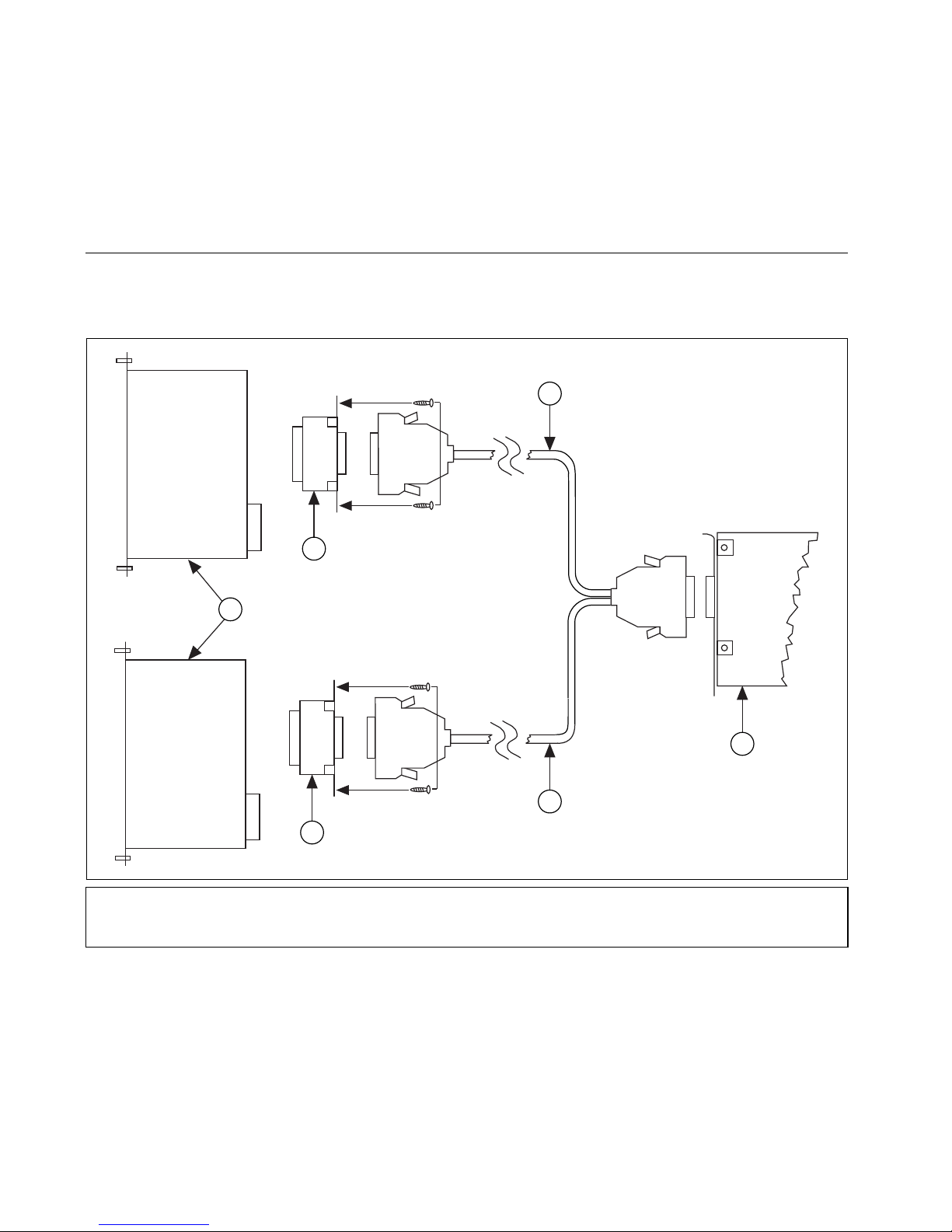
Installing the SCXI-1353 Shielded Cable Assembly
Perform the following steps to install the SCXI-1353. Refer to Figure 1 for
the installation procedure.
3
2
1
6
1 SCXI Modules
2 SCXI-1349 Shielded Cable Adapter
3 MIO-16 Cable
4
5
4 AT-MIO E Series DAQ Device
5 Extended I/O Cable
6 AI-48/DIO-24 Adapter
Figure 1. SCXI-1353 Installation
1. Turn off the computer and SCXI chassis.
2. Install the SCXI modules in the SCXI chassis following the
SCXI-1353 Shielded Cable Assembly 4 ni.com
instructions in the module user manual.
Page 5

3. Insert the 50-pin female connector on the rear of the SCXI-1349 into
the rear signal connector of the SCXI module that passes analog
signals to the 100-pin E Series DAQ device.
4. Screw the rear panel of the SCXI-1349 to the threaded strips in the rear
of the SCXI chassis to secure the adapter.
5. Connect the end of the cable labeled MIO-16 to the 68-pin connector
of the SCXI-1349.
6. Insert the 50-pin female connector on the rear of the AI-48/DIO-24
into the rear signal connector of the SCXI module or feedthrough panel
that connects to pins 51–100 of the DAQ device.
7. Screw the rear panel of the AI-48/DIO-24 to the threaded strips in the
rear of the SCXI chassis to secure the adapter.
8. Connect the end of the cable labeled EXTENDED I/O to the 68-pin
connector of the AI-48/DIO-24.
9. Connect the 100-pin end of the cable to the I/O connector of the DAQ
device.
10. Use the tie wraps to secure the cable to a fixed object to relieve the
strain on the cable. Strain relief is necessary because the SCXI-1353
has a long, stiff backshell that can exert leverage on the DAQ device
connector.
Connections and Pin Assignments
Table 1 lists the pin assignments for connections between the 100-pin
E Series DAQ device and the MIO-16 cable. Table 2 lists the pin
assignments for connections between the 100-pin E Series DAQ device and
the EXTENDED I/O cable. The 100-pin E Series DAQ device you use
determines which SCXI modules you can use with the SCXI-1353.
Table 1. MIO-16 Cable Connections
Signal Names Connector Pin Numbers
100-Pin E Series Device 100-Pin 50-Pin 68-Pin
AIGND 1, 2 1, 2 24, 27, 29, 32, 56, 59, 64, 67
ACH0 3 3 68
ACH8 4 4 34
ACH1 5 5 33
ACH9 6 6 66
ACH2 7 7 65
© National Instruments Corporation 5 SCXI-1353 Shielded Cable Assembly
Page 6

Table 1. MIO-16 Cable Connections (Continued)
Signal Names Connector Pin Numbers
100-Pin E Series Device 100-Pin 50-Pin 68-Pin
ACH10 8 8 31
ACH3 9 9 30
ACH11 10 10 63
ACH4 11 11 28
ACH12 12 12 61
ACH5 13 13 60
ACH13 14 14 26
ACH6 15 15 25
ACH14 16 16 58
ACH7 17 17 57
ACH15 18 18 23
AISENSE 19 19 62
DAC0OUT 20 20 22
DAC1OUT 21 21 21
EXTREF 22 22 20
AOGND 23 23 54, 55
DGND 24, 33 24, 33 4, 7, 9, 12, 13, 15, 18,
35, 36, 39, 44, 50, 53
DIO0 25 25 52
DIO4 26 26 19
DIO1 27 27 17
DIO5 28 28 51
DIO2 29 29 49
DIO6 30 30 16
DIO3 31 31 47
DIO7 32 32 48
+5V 34, 35 34, 35 8, 14
SCXI-1353 Shielded Cable Assembly 6 ni.com
Page 7

Table 1. MIO-16 Cable Connections (Continued)
Signal Names Connector Pin Numbers
100-Pin E Series Device 100-Pin 50-Pin 68-Pin
SCANCLK 36 36 46
EXTSTROBE* 37 37 45
PFI0/TRIG1 38 38 11
PFI1/TRIG2 39 39 10
PFI2/CONVERT* 40 40 43
PFI3/GPCTR1_SOURCE 41 41 42
PFI4/GPCTR1_GATE 42 42 41
GPCTR1_OUT 43 43 40
PFI5/UPDATE* 44 44 6
PFI6/WFTRIG 45 45 5
PFI7/STARTSCAN 46 46 38
PFI8/GPCTR0_SOURCE 47 47 37
PFI9/GPCTR0_GATE 48 48 3
GPCTR0_OUT 49 49 2
FREQ_OUT 50 50 1
Pins 1 through 9 and pins 35 through 43 on the 68-pin connector are not connected.
Table 2. Extended I/O Cable Connections
Signal Names Connector Pin Numbers
NI 6031E, NI 6033E,
NI 6061E, NI 6071E
NI 6021E, NI 6025E 100-Pin 50-Pin 68-Pin
ACH16 PC7 51 1 68
ACH24 GND 52 2 34
ACH17 PC6 53 3 33
ACH25 GND 54 4 67
ACH18 PC5 55 5 32
ACH26 GND 56 6 66
ACH19 PC4 57 7 65
© National Instruments Corporation 7 SCXI-1353 Shielded Cable Assembly
Page 8

Signal Names Connector Pin Numbers
NI 6031E, NI 6033E,
NI 6061E, NI 6071E
ACH27 GND 58 8 31
ACH20 PC3 59 9 30
ACH28 GND 60 10 64
ACH21 PC2 61 11 29
ACH29 GND 62 12 63
ACH22 PC1 63 13 62
ACH30 GND 64 14 28
ACH23 PC0 65 15 27
ACH31 GND 66 16 61
Table 2. Extended I/O Cable Connections (Continued)
NI 6021E, NI 6025E 100-Pin 50-Pin 68-Pin
ACH32 PB7 67 17 26
ACH40 GND 68 18 60
ACH33 PB6 69 19 59
ACH41 GND 70 20 25
ACH34 PB5 71 21 24
ACH42 GND 72 22 58
ACH35 PB4 73 23 23
ACH43 GND 74 24 57
AISENSE2 PB3 75 25 56
AIGND GND 76 26 22
ACH36 PB2 77 27 55
ACH44 GND 78 28 21
ACH37 PB1 79 29 20
ACH45 GND 80 30 54
ACH38 PB0 81 31 19
ACH46 GND 82 32 53
ACH39 PA7 83 33 52
SCXI-1353 Shielded Cable Assembly 8 ni.com
Page 9

Signal Names Connector Pin Numbers
NI 6031E, NI 6033E,
NI 6061E, NI 6071E
ACH47 GND 84 34 18
ACH48 PA6 85 35 17
ACH56 GND 86 36 51
ACH49 PA5 87 37 16
ACH57 GND 88 38 50
ACH50 PA4 89 39 49
ACH58 GND 90 40 15
ACH51 PA3 91 41 14
ACH59 GND 92 42 48
Table 2. Extended I/O Cable Connections (Continued)
NI 6021E, NI 6025E 100-Pin 50-Pin 68-Pin
ACH52 PA2 93 43 13
ACH60 GND 94 44 47
ACH53 PA1 95 45 46
ACH61 GND 96 46 12
ACH54 PA0 97 47 11
ACH62 GND 98 48 45
ACH55 +5V 99 49 10
ACH63 GND 100 50 44
Pins 1 through 9 and pins 35 through 43 on the 68-pin connector are not connected.
Using the SCXI-1353 with an NI 6031E, NI 6033E, NI 6061E, or NI 6071E
The MIO-16 cable connects the MIO-16 portion of the AT-MIO-64E-3
pinout to the SCXI-1349. The EXTENDED I/O cable connects the
remainder of the AT-MIO-64E-3 pinout to the AI-48/DIO-24.
You can connect the MIO-16 cable, using the SCXI-1349, to the following
SCXI modules: SCXI-1100, SCXI-1120, SCXI-1121, SCXI-1122,
SCXI-1124, SCXI-1140, SCXI-1141, SCXI-1160, SCXI-1161,
SCXI-1162, SCXI-1162HV, SCXI-1163, SCXI-1163R, SCXI-1180,
or SCXI-1181.
© National Instruments Corporation 9 SCXI-1353 Shielded Cable Assembly
Page 10

You can connect the EXTENDED I/O cable, using the AI-48/DIO-24,
to the SCXI-1180 feedthrough panel or SCXI-1181 module.
Using the SCXI-1353 with an NI 6021E or NI 6025E
The MIO-16 cable connects the MIO-16 portion of the AT-MIO-16DE-10
pinout to the SCXI-1349. The EXTENDED I/O cable connects the
remainder of the AT-MIO-16DE-10 pinout to the AI-48/DIO-24.
You can connect the MIO-16 cable, using the SCXI-1349, to the following
SCXI modules: SCXI-1100, SCXI-1120, SCXI-1121, SCXI-1122,
SCXI-1124, SCXI-1140, SCXI-1141, SCXI-1160, SCXI-1161,
SCXI-1162, SCXI-1162HV, SCXI-1163, SCXI-1163R, SCXI-1180,
or SCXI-1181.
You can connect the EXTENDED I/O cable, using the AI-48/DIO-24,
to the following SCXI modules: SCXI-1162, SCXI-1162HV, SCXI-1163,
SCXI-1163R, SCXI-1180 feedthrough panel, or SCXI-1181.
Note If the module that you are using is not listed here, please refer to the NI Web site
at
ni.com/support for technical support.
Specifications
Maximum Working Voltage
Maximum working voltage refers to the signal voltage plus the
common-mode voltage.
Channel-to-earth .....................................±15 V, installation category I
Channel-to-channel.................................±15 V, installation category I
Environmental
Operating temperature ............................0 to 50 °C
Storage temperature................................–20 to 70 °C
Humidity.................................................10 to 90% RH, noncondensing
Maximum altitude...................................2000 meters
Pollution degree (indoor use only) .........2
SCXI-1353 Shielded Cable Assembly 10 ni.com
Page 11

Safety
The SCXI-1353 meets the requirements of the following standards
for safety and electrical equipment for measurement, control, and
laboratory use:
• EN 61010-1:1993/A2:1995, IEC 61010-1:1990/A2:1995
• UL 3111-1:1994
• CAN/CSA c22.2 no. 1010.1:1992/A2:1997
Technical Support Resources
National Instruments Web Support
NI Web support is your first stop for help in solving installation,
configuration, and application problems and questions. Online
problem-solving and diagnostic resources include frequently asked
questions, knowledge bases, product-specific troubleshooting wizards,
manuals, drivers, software updates, and more. Web support is available
through the Technical Support section of
ni.com.
Worldwide Support
NI has offices located around the world to help address your support needs.
You can access our branch office Web sites from the Worldwide Offices
section of
information, support phone numbers, e-mail addresses, and current events.
If you have searched the technical support resources on our Web site
and still cannot find the answers you need, contact your local office or NI
corporate. For telephone support in the United States, dial 512 795 8248.
For telephone support outside the United States, contact your local branch
office:
Australia 03 9879 5166, Austria 0662 45 79 90 0, Belgium 02 757 00 20,
Brazil 011 3262 3599, Canada (Calgary) 403 274 9391,
Canada (Montreal) 514 288 5722, Canada (Ottawa) 613 233 5949,
Canada (Québec) 514 694 8521, Canada (Toronto) 905 785 0085,
China (Shanghai) 021 6555 7838, China (ShenZhen) 0755 3904939,
Czech Republic 02 2423 5774, Denmark 45 76 26 00,
Finland 09 725 725 11, France 01 48 14 24 24, Germany 089 741 31 30,
Greece 30 1 42 96 427, Hong Kong 2645 3186, India 91 80 535 5406,
Israel 03 6393737, Italy 02 413091, Japan 03 5472 2970,
Korea 02 3451 3400, Malaysia 603 9596711, Mexico 001 800 010 0793,
Netherlands 0348 433466, New Zealand 09 914 0488,
Norway 32 27 73 00, Poland 0 22 3390 150, Portugal 351 210 311 210,
Russia 095 238 7139, Singapore 2265886, Slovenia 386 3 425 4200,
ni.com. Branch office Web sites provide up-to-date contact
© National Instruments Corporation 11 SCXI-1353 Shielded Cable Assembly
Page 12

South Africa 11 805 8197, Spain 91 640 0085, Sweden 08 587 895 00,
Switzerland 056 200 51 51, Taiwan 02 2528 7227,
United Kingdom 01635 523545
*320982B-01*
320982B-01 Jan02
 Loading...